
Stability Analysis of Isolated Roof in Overlapping Goaf Based on Strength Reduction

Abstract
1. Introduction
2. Strength Reduction Method for Stability Analysis of an Isolated Roof
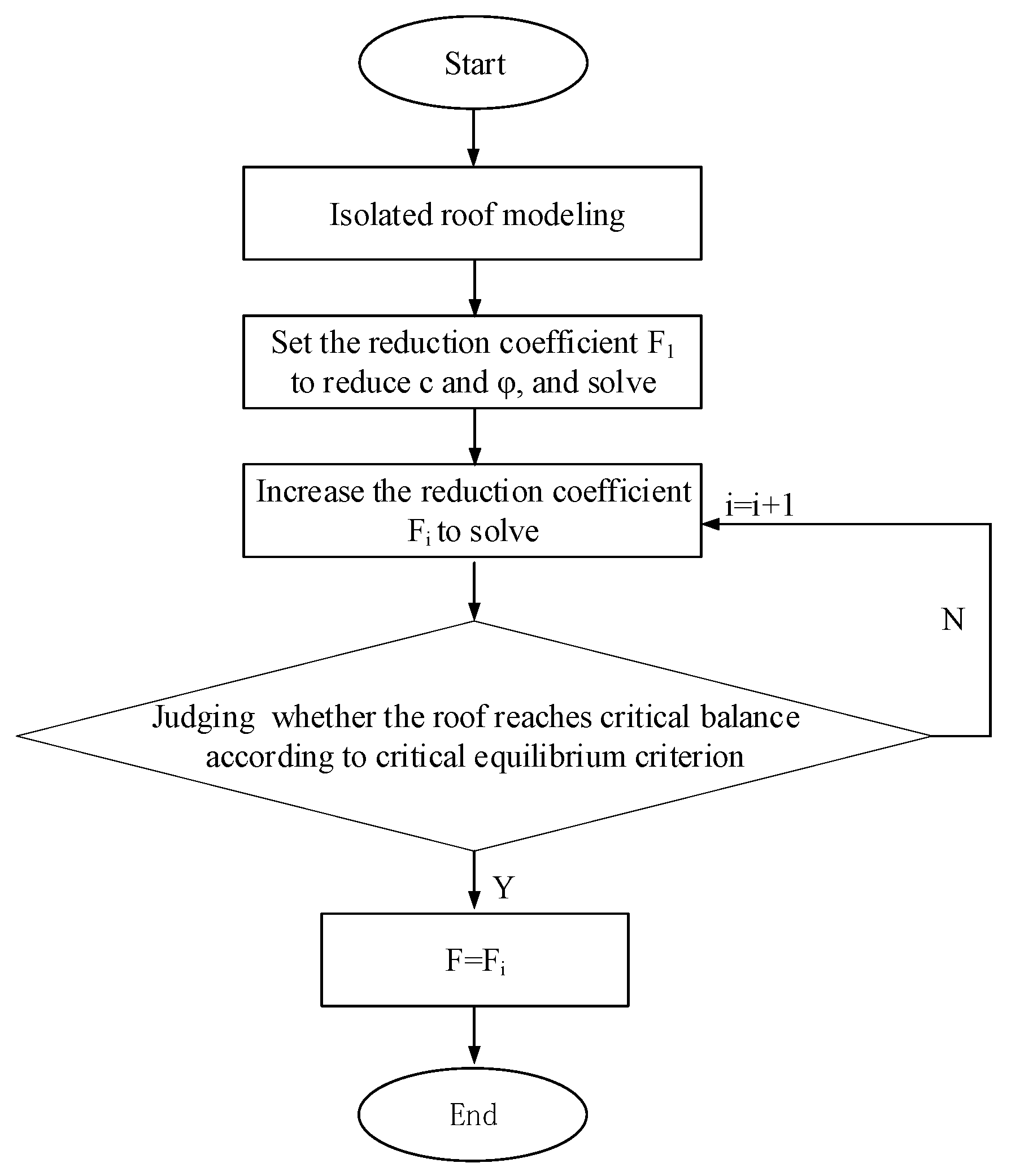
2.1. Calculation Process of the Strength Reduction Method
- (1)
- Establish a model of the overlapping goaf, including the upper pillar, the isolated roof, and the lower pillar;
- (2)
- Calculate the model by using the initial parameters c0 and φ0 of the model until the calculation converges;
- (3)
- Continuously reduce the cohesion and friction until critical equilibrium is reached;
- (4)
- Using Equations (1) and (2), the safety coefficient Fs of the isolated roof is obtained;
- (5)
- Change the relative position of the upper and lower pillars, and calculate the safety factor of the roof by the above steps (1)~(4).
2.2. Calculation Model and Scheme
3. Stability Analysis of Isolated Roof Under the Staggered Support
3.1. Relationship Between the Safety Factor and the Relative Position of the Pillars
- (1)
- The first stage (L1) is the rapid decline of the safety factor. The safety factor of the isolated roof decreases rapidly with the increase of the dislocated width, and the safety factor decreases almost in a steep straight line during this stage. The upper and lower pillars are gradually misaligned from complete alignment, which causes the pressure from the overlying strata to transfer from the upper pillar to the isolated roof and then to the lower pillar. The roof begins to bear part of the load, and its safety reserve drops sharply from large to small.
- (2)
- The second stage is the L2 where the safety factor changes from down to up. When the dislocated width continues to increase, the safety factor no longer shows the rapid decline in the L1 stage but instead enters the interval from decline to rise. In this interval, the curve first slowly drops and reaches the bottom when the dislocated width is 20 m and then begins to enter the rising period. During this stage, although the variation range of the safety factor is not significant, its value is less than 1.5. Obviously, the continuous low movement of the safety factor may threaten the stability of the roof and even easily lead to roof collapse.
- (3)
- The third stage (L3) is the rapid increase of the safety factor. Due to the symmetry of the upper and lower pillars, if the dislocated width continues to increase, the spacing between the upper and lower pillars will be reduced, which is equivalent to the pillars moving towards each other. The load transfer is basically the same as that in the first stage, mainly between the upper and lower pillars, the stress on the roof is greatly reduced, and the safety factor is rapidly increased.
3.2. The Relationship Between the Failure Type of the Isolated Roof and the Overlap Rate of the Pillars
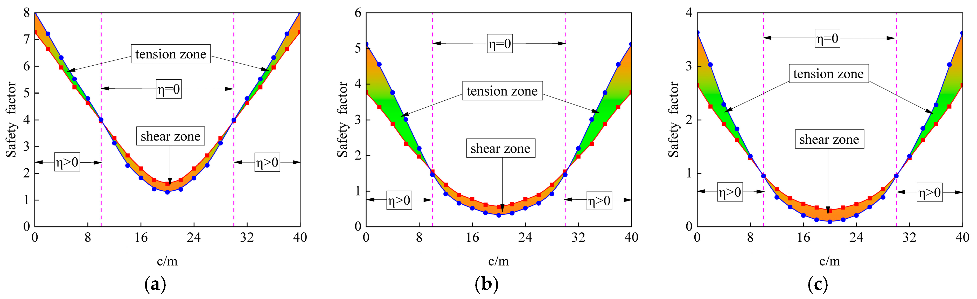
3.3. The Safety Factor of the Isolated Roof When the Overlap Rate Is 0
4. Effect of Width Ratio and Dislocated Width on the Stability of the Isolated Roof
4.1. Characterization of the Variation in the Safety Factor for Different Width Ratios
4.2. Characteristics of the Destabilization Evolution of the Isolated Roof Under Different Dislocated Widths
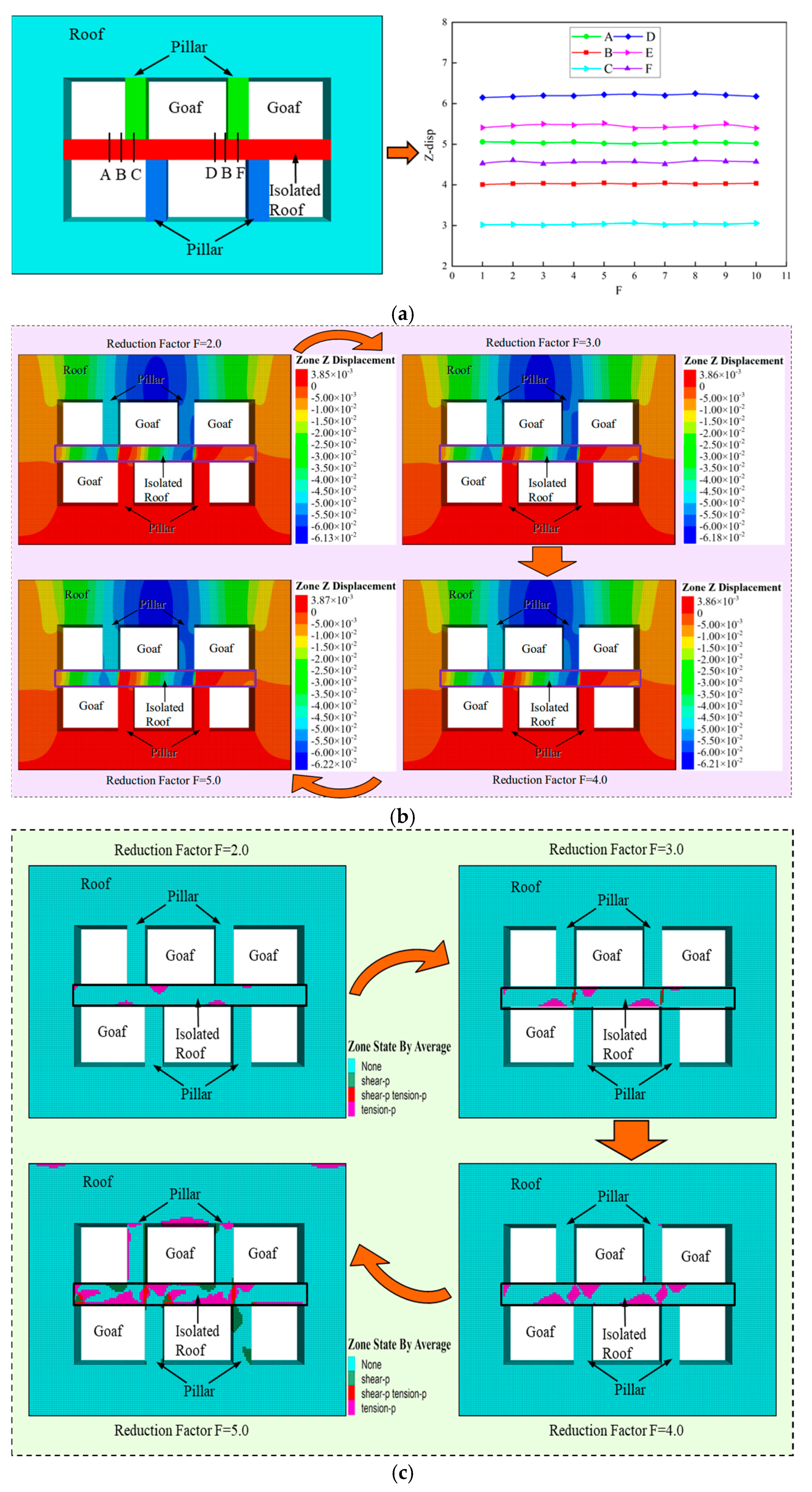
- (1)
- The distribution of the plastic zone of the isolated roof is closely related to the dislocated width, and it has extremely significant symmetry. The smaller the dislocated width, the more obvious the bearing characteristics of the pillar, and the more sparse the failure units in the roof of the interlayer. On the contrary, the greater the dislocated width, the more obvious the bearing characteristics of the roof, and the denser the failure units. In addition, the distribution of the plastic zone shows very clear characteristics. If the center line of the upper and lower pillars is set as the axis, the failure units are concentrated on both sides of the axis and basically symmetrically distributed.
- (2)
- When the upper and lower ore pillars are completely aligned, the strength of the roof is continuously reduced until it is damaged, then it can be found that the roof has tensile damage in the process of reduction, and the plastic zone is shaped like an I-beam. This phenomenon of course has a reasonable explanation: when the dislocated width is 0, the upper and lower pillars can be regarded as a whole structure, and the pressure from the overlying strata can be smoothly transmitted to the floor through this whole structure. The roof is not subjected to shear, so there are few shear failure units in the roof. However, due to its own gravity, when the tensile strength is constantly reduced, a large number of tensile damage units will eventually be generated, resulting in damage to the roof.
- (3)
- When the upper and lower pillars are misaligned, the pressure from the overlying strata must be transmitted downwards through the partition roof, which plays a “connecting link” role in the support system. At this point, the top plate of the interlayer is subjected to both tensile stress and shear, resulting in tensile and shear zones. But the two occur at different locations, with tensile failure mainly occurring in the opposite area where the interlayer roof contacts the pillars, and shear failure mainly occurring in the area between the upper and lower pillars.
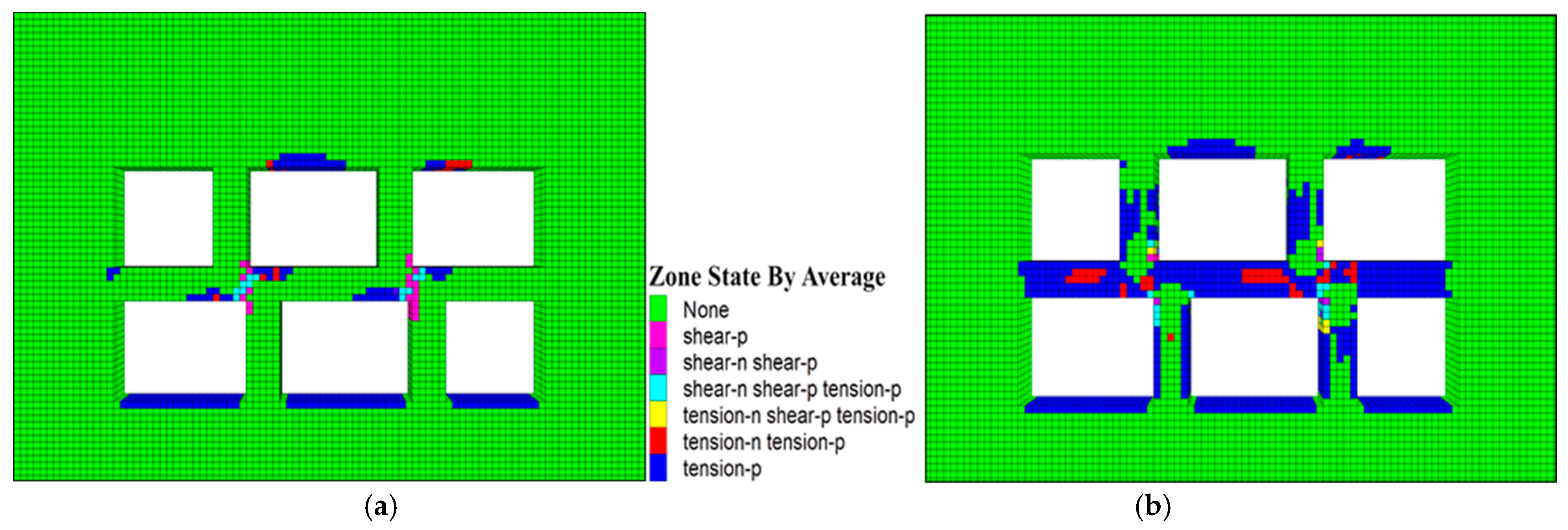
- (4)
- The evolution of the failure scope and the failure form of the isolated roof show different laws respectively. The evolution law of the failure scope is that the plastic zone is initially born around the pillar, and with the increase of the dislocation, the failure unit gradually expands outwards and finally penetrates through the roof. Furthermore, the evolution of plastic zone morphology is as follows: the initial failure zone is limited to the periphery of the pillar, the tensile zone is like a folded line, and the shear zone is a diagonal strip. With the increase of the dislocation, the damage units continue to gather, and the plastic zone begins to expand outward, which leads to the continuous expansion of the boundaries of the plastic zone. Ultimately, the tensile zone evolves from a single folded line into a large wave, and the shear zone, which looks like a diagonal strip, evolves into a square strip.

5. Discussion
5.1. Criteria for Judging the Critical Equilibrium State of the Isolated Roof
5.2. The Complexity of Overlapping Goafs
6. Conclusions
- (1)
- It is proposed to adopt the dislocated width to express the relative position relationship between the upper and lower pillars. The study shows that the increase of the dislocated width will lead to the continuous change of the safety factor of the isolated roof. The curve of the safety factor can be divided into three stages: the sharp decline stage, the decline-to-increase stage and the rapid increase stage. In the first stage, the safety factor is inversely correlated with the dislocated width, and the safety reserve drops sharply; In the second stage, the safety factor changes only slightly, and the curve firstly decreases slowly to the inflection point, and then turns to rise, and the stability of the roof is the worst; In the third stage, the safety factor is positively correlated with the dislocated width, and the increase of the dislocated width makes the safety factor rise rapidly, which leads to the obvious enhancement of the stability of the roof.
- (2)
- The overlap rate of pillars determines the type of failure of the roof but not the decisive factor of the safety factor. When the overlap rate is η > 0, the tensile safety factor is less than the shear safety factor, which leads to the tensile failure of the roof more easily. The greater the value, the greater the safety factor of the roof. However, when the overlap rate is η = 0, the shear safety factor is less than the tensile safety factor, resulting in the roof being more prone to shear failure. During this stage, the safety factor changes with the change in the dislocated width but is not related to the overlap rate.
- (3)
- The width ratio is the key factor affecting the stability of the roof. It is found that the width ratio λ = 2 can be the critical value of the safety reserve. When λ ˂ 2, the safety factor F of the roof is large, and the safety reserve is sufficient, but F decreases sharply with the increase of λ in this stage. On the contrary, when λ ˃ 2, with the increase of the width ratio λ, F slowly decreases and gradually tends to 0. Accordingly, reducing the width ratio helps to improve the stability of the roof, and in order to prevent it from destabilizing, the width ratio should not be larger than 2.
- (4)
- The study reveals the evolution of the plastic zone of the roof. The failure units are concentrated and symmetrically distributed on both sides of the center line of the upper and lower pillars. The plastic zone is born around the pillar at the beginning, where the tensile failure zone is like a fold line, and the shear failure zone is an oblique strip. With the increase of the dislocated width, resulting in the accumulation of failure units, which promotes the acceleration of the expansion of the plastic zone. Gradually, the tensile failure zone changes into a wavy line, and the width of the shear failure zone becomes a square strip.
Author Contributions
Funding
Institutional Review Board Statement
Informed Consent Statement
Data Availability Statement
Acknowledgments
Conflicts of Interest
References
- Shang, Z.; Tang, S.; Jiao, W.; Liu, C. Failure Probability of Goaf in Large-Scale Based on Simulation of FLAC3D. Rock Soil Mech. 2014, 35, 3000–3006. [Google Scholar]
- Ma, H.; Wang, J.; Wang, Y. Study on mechanics and domino effect of large-scale goaf cave-in. Saf. Sci. 2012, 50, 689–694. [Google Scholar] [CrossRef]
- Chen, Q.; Liu, Y. Study on the size effect of goaf stability. Disaster Adv. 2013, 5, 1597–1601. [Google Scholar]
- Zhao, Y.; Wu, Q.; Wang, W.; Wan, W.; Zhao, F. Strength Reduction Method to Study Stability of Goaf Overlapping Roof based on Catastrophe Theory. Chin. J. Rock Mech. Eng. 2010, 29, 1424–1434. [Google Scholar]
- Jiang, L.; Jiao, H.; Wang, Y.; Wang, G. Comprehensive Safety Factor of Roof in Goaf Underdeep High Stress. J. Cent. South Univ. 2021, 28, 595–603. [Google Scholar] [CrossRef]
- Xie, X.; Zhang, X. Research on Hard Rock Pillar Stability Prediction Based on SABO-LSSVM Model. Appl. Sci. 2024, 14, 7733. [Google Scholar] [CrossRef]
- Kim, J.G.; Ali, M.; Yang, H. Robust Design of Pillar Arrangement for Safe Room-and-Pillar Mining Method. Geotech. Geol. Eng. 2019, 37, 1931–1942. [Google Scholar] [CrossRef]
- Sherizadeh, T.; Kulatilake, P. Assessment of roof stability in a room and pillar coal mine in the US using three-dimensional distinct element method. Tunn. Undergr. Space Technol. 2016, 59, 24–37. [Google Scholar] [CrossRef]
- Zhang, G.; Li, Q.; Zhang, Y.; Du, F. Failure characteristics of roof in working face end based on stress evolution of goaf. Geomech. Geophys. Geo-Energy Geo-Resour. 2021, 7, 1–22. [Google Scholar] [CrossRef]
- Jiang, L.; Jiao, H.; Xie, B.; Yang, H. Study on Safety Coefficient of Sedimentary Bauxite Strip Pillar under Valley Terrain. Int. J. Environ. Res. Public Health 2022, 19, 10991. [Google Scholar] [CrossRef]
- Ren, Q.; Wang, F.; Chen, B.; Zhao, M.; Yang, M. Study on Stability Prediction of Pillars Based on Bieniawski Pillar Strength Formula: A Case of a Phosphate Mine. Geotech. Eng. Geol. Eng. 2020, 38, 4033–4044. [Google Scholar] [CrossRef]
- Liu, Z.; Luo, T.; Li, X.; Li, X.; Huai, Z.; Wang, S. Construction of reasonable pillar group for undersea mining in metal mine. Trans. Nonferr. Met. Soc. China 2018, 28, 757–765. [Google Scholar] [CrossRef]
- Esterhuizen, G.; Dolinar, D.; Ellenberger, J. Pillar strength in underground stone mines in the United States. Int. J. Rock Mech. Min. Sci. 2011, 48, 42–50. [Google Scholar] [CrossRef]
- Garza-Cruz, T.; Pierce, M.; Board, M. Effect of shear stresses on pillar stability: A back analysis of the troy mine experience to predict pillar performance at Montanore Mine. Rock Mech. Rock Eng. 2019, 52, 4979–4996. [Google Scholar] [CrossRef]
- Slaker, B.; Murphy, M.; Rashed, G.; Gangrade, V.; Floyd, K. Monitoring of multiple-level stress interaction at two underground limestone mines. Mine Metall. Explor. 2021, 38, 623–633. [Google Scholar] [CrossRef]
- Zhao, Y.; Wang, W.; Zhao, F.; Wan, W. Strength Reduction Method to Study Safety of Multilayer Goafs Isolation Roof. J. China Coal Soc. 2010, 35, 1257–1262. [Google Scholar] [CrossRef]
- He, Z.; Peng, Z.; Cao, P.; Lin, H. Numerical Analysis for Roof Stability of Double Gob Area After Excavation by FLAC3D. J. Cent. South Univ. (Sci. Technol.) 2009, 40, 1066–1071. [Google Scholar]
- Mukhlisin, M.; Baidillah, M.; Ibrahim, A.; Taha, M. Effect of soil hydraulic properties model on slope stability analysis based on strength reduction method. J. Geol. Soc. India 2014, 83, 586–594. [Google Scholar] [CrossRef]
- Chen, X.; Ren, J.; Wang, D.; Lyu, Y.; Zhang, H. A generalized strength reduction concept and its applications to geotechnical stability analysis. Geotech. Eng. Geol. Eng. 2019, 37, 2409–2424. [Google Scholar] [CrossRef]
- Yuan, W.; Bai, B.; Li, X.; Wang, H. A strength reduction method based on double reduction parameters and its application. J. Cent. South Univ. Technol. 2013, 20, 2555–2562. [Google Scholar] [CrossRef]
- Liu, X.; An, L.; Zhang, F. Analysis on roof stability of gob area based on thin plate theory. J. Northeast. Univ. 2012, 33, 1628–1632. [Google Scholar]
- Xie, X.; Deng, R.; Dong, X.; Yan, Z. Stability of goaf group system based on catastrophe theory and rheological theory. Rock Soil Mech. 2018, 39, 1963–1972. [Google Scholar] [CrossRef]
- Liu, H.; Hu, Q.; Wang, J.; Li, J. Analysis on stability of pillar and stiff roof system in the gob area. J. Coal Sci. Eng. 2009, 15, 206–209. [Google Scholar] [CrossRef]
- Qiu, H.; Huang, M.; Weng, Y. Stability Evaluation and Structural Parameters Optimization of Stope Based on Area Bearing Theory. Minerals 2022, 12, 808. [Google Scholar] [CrossRef]
- Zhu, D.; Song, X.; Li, H.; Liu, Z.; Wang, C.; Huo, Y. Cooperative load-bearing characteristics of a pillar group and a gob pile in partially caved areas at shallow depth. Energy Sci. Eng. 2020, 8, 89–103. [Google Scholar] [CrossRef]
- Singh, G.; Singh, U.; Murthy, V. Application of Numerical Modeling for Strata Control in Mines. Geotech. Geol. Eng. 2010, 28, 513–524. [Google Scholar] [CrossRef]
- Zhang, M.; Zhu, W.; Hou, Z. Numerical Simulation for Determining the Safe Roof Thickness and Critical Goaf Span. J. Min. Saf. Eng. 2012, 29, 543–548. [Google Scholar]
- Jiang, L.; Zhang, P.; Chen, L.; Hao, Z.; Sainoki, A.; Mitri, H.; Wang, Q. Numerical approach for goaf-side entry layout and yield pillar design in fractured ground conditions. Rock Mech. Rock Eng. 2017, 50, 3049–3071. [Google Scholar] [CrossRef]
- Mortazavi, A.; Hassani, F.; Shabani, M. A numerical investigation of rock pillar failure mechanism in underground openings. Comput. Geotech. 2009, 36, 691–697. [Google Scholar] [CrossRef]
- Xu, Z.; Xu, W.; Zhu, Z.; Zhao, J. Research on monitoring and stability evaluation of ground subsidence in gypsum mine goaf. Front. Environ. Sci. 2023, 10, 1097874. [Google Scholar] [CrossRef]
- Li, X.; Qiu, J.; Zhao, Y.; Chen, Z.; Li, D. Instantaneous and long-term deformation characteristics of deep room-pillar system induced by pillar recovery. Trans. Nonferrous Met. Soc. China 2020, 30, 2775–2791. [Google Scholar] [CrossRef]
- Ji, S.; He, H.; Karlovsek, J. Application of superposition method to study the mechanical behaviour of overlying strata in longwall mining. Int. J. Rock Mech. Min. Sci. 2021, 146, 104874. [Google Scholar] [CrossRef]
- Zhou, Z.; Chen, L.; Zhao, Y.; Zhao, T.; Cai, X.; Du, X. Experimental and numerical investigation on the bearing and failure mechanism of multiple pillars under overburden. Rock Mech. Rock Eng. 2017, 50, 995–1010. [Google Scholar] [CrossRef]
- Guo, J.; Cheng, X.; Lu, J.; Zhao, Y.; Xie, X. Research on factors affecting mine wall stability in isolated pillar mining in deep mines. Minerals 2022, 12, 623. [Google Scholar] [CrossRef]


| Material | E/GPa | σt/MPa | Poisson’s Ratio | Cohesion /MPa | Friction/° |
|---|---|---|---|---|---|
| Ore | 12.3 | 0.7 | 0.25 | 3.8 | 27.5 |
| c/m | Ft | Fs | Status | Depth/m | c/m | Ft | Fs | Status | Depth/m |
|---|---|---|---|---|---|---|---|---|---|
| 10 | 3.96 | 3.98 | stability | 100 | 10 | 0.95 | 0.94 | stability | 800 |
| 12 | 3.32 | 3.13 | stability | 12 | 0.70 | 0.55 | stability | ||
| 14 | 2.67 | 2.29 | stability | 14 | 0.53 | 0.37 | stability | ||
| 16 | 2.18 | 1.83 | stability | 16 | 0.43 | 0.21 | stability | ||
| 18 | 1.74 | 1.41 | instability | 18 | 0.36 | 0.13 | stability | ||
| 20 | 1.61 | 1.29 | instability | 20 | 0.30 | 0.09 | stability | ||
| 22 | 1.74 | 1.40 | instability | 22 | 0.36 | 0.13 | stability | ||
| 24 | 2.18 | 1.82 | stability | 24 | 0.42 | 0.21 | stability | ||
| 26 | 2.67 | 2.30 | stability | 26 | 0.53 | 0.37 | stability | ||
| 28 | 3.31 | 3.13 | stability | 28 | 0.70 | 0.55 | stability | ||
| 30 | 3.96 | 3.97 | stability | 30 | 0.95 | 0.94 | stability |
Disclaimer/Publisher’s Note: The statements, opinions and data contained in all publications are solely those of the individual author(s) and contributor(s) and not of MDPI and/or the editor(s). MDPI and/or the editor(s) disclaim responsibility for any injury to people or property resulting from any ideas, methods, instructions or products referred to in the content. |
© 2025 by the authors. Licensee MDPI, Basel, Switzerland. This article is an open access article distributed under the terms and conditions of the Creative Commons Attribution (CC BY) license (https://creativecommons.org/licenses/by/4.0/).
Share and Cite
Liu, C.; Zhao, K.; Zeng, P.; Gong, C. Stability Analysis of Isolated Roof in Overlapping Goaf Based on Strength Reduction. Appl. Sci. 2025, 15, 3067. https://doi.org/10.3390/app15063067
Liu C, Zhao K, Zeng P, Gong C. Stability Analysis of Isolated Roof in Overlapping Goaf Based on Strength Reduction. Applied Sciences. 2025; 15(6):3067. https://doi.org/10.3390/app15063067
Chicago/Turabian StyleLiu, Chang, Kui Zhao, Peng Zeng, and Cong Gong. 2025. "Stability Analysis of Isolated Roof in Overlapping Goaf Based on Strength Reduction" Applied Sciences 15, no. 6: 3067. https://doi.org/10.3390/app15063067
APA StyleLiu, C., Zhao, K., Zeng, P., & Gong, C. (2025). Stability Analysis of Isolated Roof in Overlapping Goaf Based on Strength Reduction. Applied Sciences, 15(6), 3067. https://doi.org/10.3390/app15063067