Article

Development of Co-Axial Fibres Composed of CA (Mn 50,000) and PEGs (600 and 1000): Evaluation of the Influence of the Coagulation Bath

by
Nathalia Hammes
1,2,*,†,
José Monteiro
3,†,
Iran Rocha Segundo
1,
Helena P. Felgueiras
2,
M. Manuela Silva
4,
Manuel F. M. Costa
5 and
Joaquim Carneiro
1,*
1
Centre of Physics of Minho and Porto Universities (CF-UM-UP), Azurém Campus, University of Minho, Av. da Universidade, 4800-058 Guimarães, Portugal
2
Centre for Textile Science and Technology (2C2T-UMinho), Azurém Campus, University of Minho, Av. da Universidade, 4800-058 Guimarães, Portugal
3
Earth Sciences Department of the University of Minho, Gualtar Campus, University of Minho, R. da Universidade, 4710-057 Braga, Portugal
4
Centre of Chemistry of University of Minho (CQ-UMinho), Gualtar Campus, University of Minho, R. da Universidade, 4710-057 Braga, Portugal
5
Centre of Physics of Minho and Porto Universities (CF-UM-UP), Gualtar Campus, University of Minho, R. da Universidade, 4710-057 Braga, Portugal
*
Authors to whom correspondence should be addressed.
These authors contributed equally to this work.
Appl. Sci. 2025, 15(6), 3028; https://doi.org/10.3390/app15063028
Submission received: 29 January 2025 / Revised: 23 February 2025 / Accepted: 10 March 2025 / Published: 11 March 2025
(This article belongs to the Section Materials Science and Engineering)

Abstract

:
Rapid urbanisation and industrialisation have intensified the Urban Heat Island (UHI) effect, significantly increasing energy demand for thermal comfort. Urban buildings consume considerable energy throughout the year, which can be reduced by incorporating Phase Change Materials (PCMs) into building materials. PCMs effectively regulate temperature by storing and releasing heat as latent heat during phase transitions. However, to prevent leakage, PCMs can be encapsulated in co-axial polymeric Phase Change Fibres (PCFs), representing an innovative approach in scientific research. This study optimised the coagulation bath and produced PCFs using commercial cellulose acetate as the sheath and polyethylene glycol (PEG 600 and 1000) as the core via the wet-spinning method. The first part of this work investigated the coagulation bath using Attenuated Total Reflectance-Fourier Transform Infrared Spectroscopy (ATR-FTIR) analyses of the characteristic peak areas. In contrast, the second part examined the PCFs’ morphological, chemical and thermal properties using Bright-field microscopy, ATR-FTIR, Differential Scanning Calorimetry (DSC) and Thermogravimetric Analysis (TGA) techniques. The results demonstrated the successful production of PCFs with an optimised coagulation bath. Bright-field microscopy and ATR-FTIR confirmed the well-defined morphology and the presence of PEG in the fibre core. TGA analysis showed high thermal stability in the PCFs, with mass loss observed at high degradation temperatures, ranging from ~264 °C to 397 °C for the PCFs with PEG 600 and from ~273 °C to 413 °C for the PCFs with PEG 1000. Meanwhile, DSC analysis revealed melting points of ~12.64 °C and 11.04 °C, with endothermic enthalpy of ~39.24 °C and 30.59 °C and exothermic enthalpy of ~50.17 °C and 40.93 °C, respectively, for PCFs with PEG 600, and melting points of ~40.32 °C and 41.13 °C, with endothermic enthalpy of ~83.47 °C and 98.88 °C and exothermic enthalpy of ~84.66 °C and 88.79 °C, respectively, for PCFs with PEG 1000. These results validate the potential of PCFs for applications in building materials for civil engineering, promoting thermal efficiency and structural stability.

1. Introduction

Thermal comfort in urban buildings has become an increasing challenge due to the intensification of the Urban Heat Island (UHI) phenomenon [1,2], aggravated by global warming and rapid urbanisation. UHI results in higher temperatures in cities compared with nearby rural areas due to the ability of building materials to absorb and retain heat throughout the day [1,3].
This thermal rise increases energy demand in urban buildings, especially for air conditioning, significantly impacting energy consumption and citizens’ well-being [4,5]. Furthermore, the lack of thermal control in indoor environments can compromise quality of life, reducing productivity and increasing health problems [6]. Developing effective strategies for improving thermal comfort in urban buildings and mitigate UHI is a priority for modern cities [2,4] (Figure 1).
Latent heat storage materials (LHTS) [7,8], commonly known as Phase Change Materials (PCMs), have emerged as a promising solution for addressing thermal regulation challenges [9]. These materials act as temperature stabilisers by absorbing heat during the day and releasing it at night through latent heat storage, thereby maintaining a more consistent thermal environment. When incorporated into civil engineering building materials such as cement mortar [10] and asphalt [11], PCMs can help mitigate UHI-related issues, improve thermal comfort, and increase energy efficiency [12]. Drissi S. et al. [13] show that despite their high potential, conventional methods of incorporating PCMs often face limitations such as property instability and leakage, compromising their effectiveness in practical applications. These challenges highlight the need for innovative approaches to encapsulate and use PCMs more effectively in sustainable building practices [10].
Aiming to improve these limitations, developing co-axial phase change polymer fibres (PCFs) [14] represents a significant innovation for the scientific world. Produced using the wet-spinning method [15], these PCFs encapsulate PCMs in a well-defined core-sheath structure, preventing leaks and ensuring thermal stability [16]. This approach provides controlled release and absorption of thermal energy, making PCFs particularly suitable for use in civil construction materials to improve urban thermal regulation [17,18].
Among the PCFs’ production steps, optimising the coagulation bath is fundamental [14,19,20], as it directly influences the fibre sheath-core structure’s formation, integrity and functionality. Aneem T. et al. [21] studied how the coagulation process can control the exchange rate between the solvent and the coagulant, affecting the final morphology of the fibres, such as the thickness of the sheath and the uniformity of the core. Recent studies indicate that different parameters such as temperature, composition and length of the coagulation bath play essential roles in obtaining high-quality PCFs [21,22]. An optimised coagulation bath promotes the removal of toxic solvents, such as dimethylformamide (DMF) [14,23], improving the structural stability of the fibres and reducing environmental risks. Furthermore, this step is essential to avoid defects, such as ruptures, which could compromise the encapsulation of PCMs and their thermal storage capacity, ensuring their efficiency for long-term applications in civil engineering materials. Therefore, the appropriate choice of the best coagulation bath is essential for the overall performance of PCFs and their application in sustainable thermal regulation solutions.
To the best of the authors’ knowledge, this is one of the first studies to explore coagulation bath optimisation and evaluate morphological, chemical, and thermal properties with a specific PCF structure. In this work, PCFs containing cellulose acetate (CA) in the sheath and polyethylene glycol (PEG 600 and 1000) in the core were developed for subsequent evaluation of morphological, chemical and thermal properties. It is worth noting that this process is low-cost, addressing the objectives of improving urban thermal comfort and promoting sustainable construction practices for civil engineering applications.

2. Materials and Methods

2.1. Materials

The experimental section that follows requires the subsequent list of materials:
  • Commercial cellulose acetate powder (CA, Sigma-Aldrich, St. Louis, MO, USA), with an acetyl content of 39.8 wt.%, average Mn = 50,000. It was selected because it is a non-toxic and natural material found in plants, and it is derived from cellulose; it is used to form the outer part of the co-axial fibres, generating a protective sheath [24].
  • N,N-Dimethylformamide (DMF, 99.8%, Sigma-Aldrich, St. Louis, MO, USA). It was selected to dissolve CA because of its chemical compatibility (enhanced solubility) and moderate evaporation rate.
  • Polyethylene glycol (600 and 1000) H(OCH2CH2)nOH, MP: ± 17–22 °C and MP: ± 37–40 °C (PEGs 600 and 1000, Thermo Fisher Scientific, Waltham, MA, USA). These are widely used PCMs. They were chosen for the PCF core due to their temperature range, unreactive nature towards other substances, phase change abilities, and heat storage capacity [25].
  • Distilled water (dH2O) was used to dissolve PEGs;
All reagents and polymers were used without further purification.

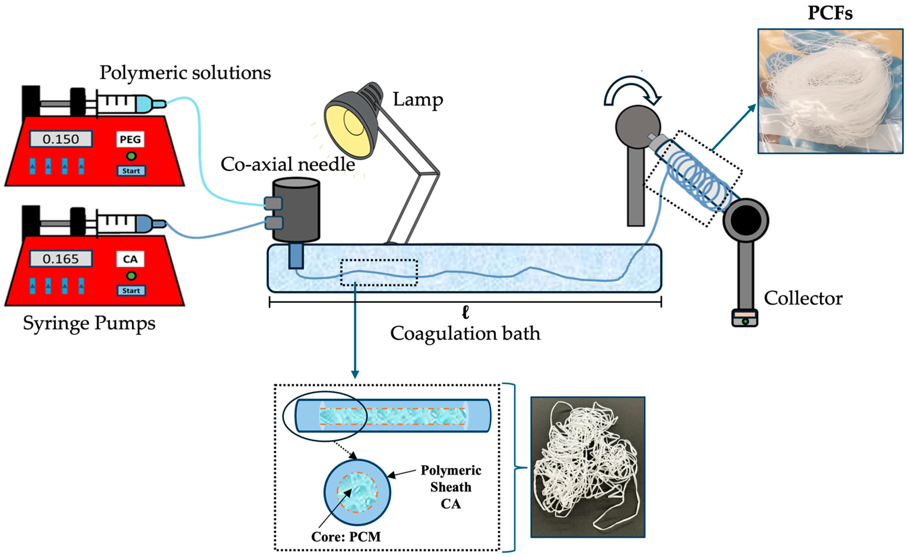
2.2. Wet-Spinning Production

In short, CA forms a protective sheath so that PEG, in the core, can store and release heat without leaking, making PCFs useful for incorporation into civil engineering materials and thermal control in different environments.
The different fibres studied in this work were produced via a wet-spinning system [26]. Solutions of CA (Mn 50,000, 10 wt.%) and PEGs (600 and 1000, 0.90 g/mL) were prepared by dissolving the CA in DMF and the PEGs in dH2O. Both solutions were stirred overnight at 50 °C to ensure complete dissolution. Before production, the solutions were left to stand at room temperature (RT) for 1 h to eliminate air bubbles and reach the ideal RT. The wet-spinning apparatus consisted of two syringe pumps NE-1000 (New Era Pump Systems Inc., Farmingdale, NY 11735, USA), a uniaxial needle (18 G) and a co-axial needle (11 G and 21 G), three coagulation baths of different sizes (dH2O at 20 °C) and an automated fibre collector. The distance between the needle and the collector varied according to the optimisation of the coagulation bath.
During the production (Figure 2), the CA solution was ejected through the external nozzle of the co-axial needle at a speed of 0.165 mL/min. In contrast, the PEG solution was ejected through the internal nozzle at controlled rates, varying between 0.140 and 0.150 mL/min. Upon contact with the coagulation bath, the CA coagulates rapidly, forming a protective sheath around the PEG core. The fibres were collected at 5 rpm, ensuring uniformity and ease of handling.

2.3. Nomenclature of the Fibres

The PCF samples were designated according to a standard nomenclature:
PCF:X/A_B_C. In this structure, X refers to the molecular weight of the CA (Mn 50,000), A indicates the molecular weight of the PEG 600 or PEG 1000, B indicates the concentration of the PEGs (0.90 g/mL), and C represents the ejection rate of the PEGs (0.140 or 0.150 mL/min).
For example, the nomenclature PCF:50/600_90_140 describes a PCF in which the following is true:
  • 50 refers to the molecular weight of the CA (Mn 50,000);
  • 600 indicates a molecular weight of the PEG;
  • 90 indicates a concentration of 0.90 g/mol of the PEGs;
  • 150 corresponds to a 0.150 mL/min ejection rate for the PEGs.
It is worth mentioning that uniaxial fibres (Funi) and hollow fibres (Fhol), used only for the study of coagulation bath optimisation, were not included in the standardised nomenclature. Thus, this nomenclature was applied exclusively to the PCF samples, ensuring clarity in the presentation of the results.

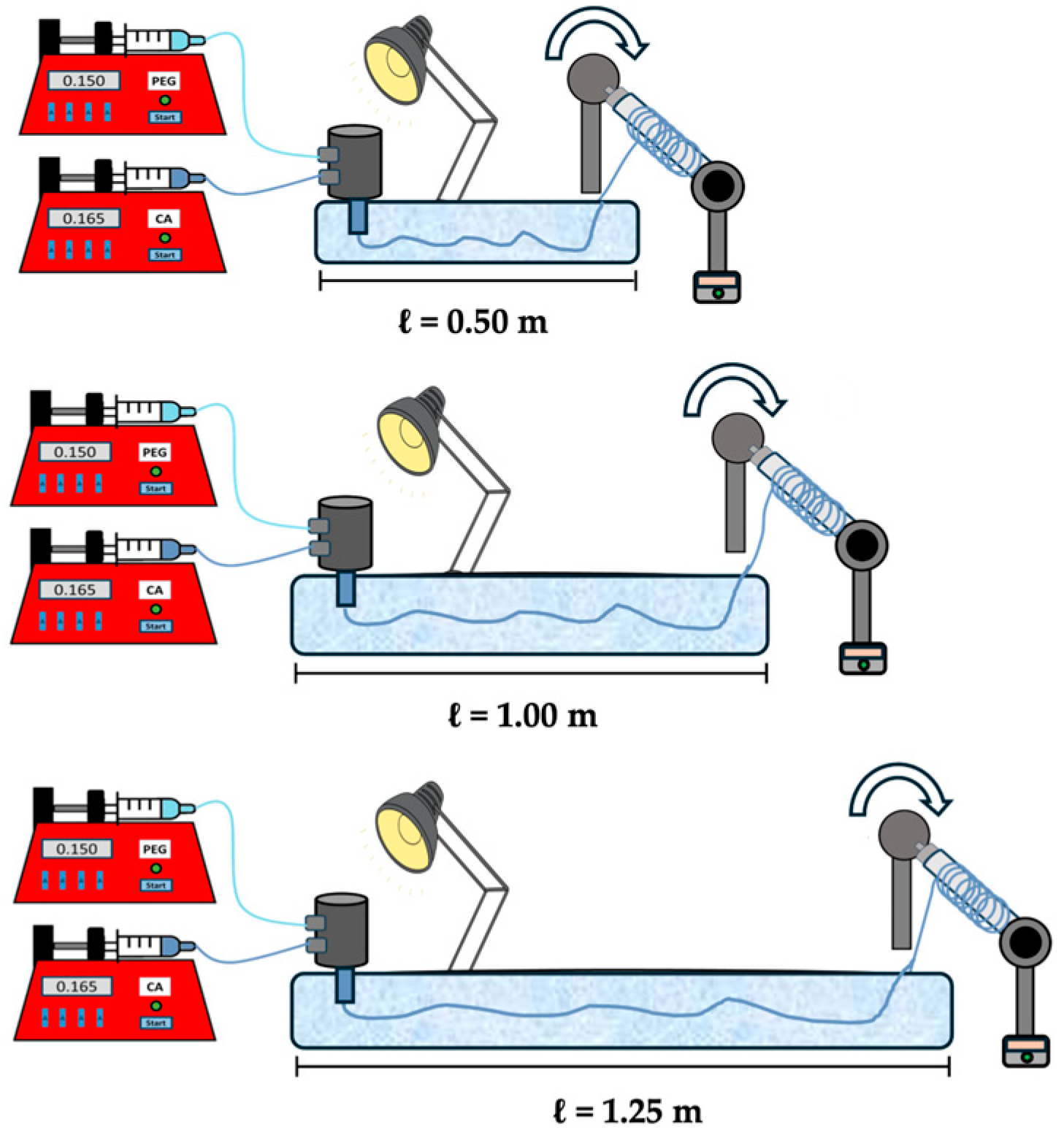
2.4. Coagulation Bath Optimisation

Before the production of PCFs, Funi and Fhol composed of CA (Mn 50,000, 10 wt.%) were produced. To optimise the production of PCFs incorporated with PEGs, an initial study was carried out focusing on the removal of the DMF solvent, which, in addition to having toxic properties, can pose risks in applications of civil engineering materials, as it may affect the mechanical integrity of the structures. In addition, an optimised bath is essential for coagulating the CA sheath, which is responsible for protecting the PEGs ejected into the core. Therefore, various coagulation bath lengths (Figure 3) of 0.50, 1.00, and 1.25 m were tested to mitigate these effects. The Funi and Fhol used at this time were named Funi_50, Funi_100, Funi_125, Fhol_50, Fhol_100, and Fhol_125. The values of 50, 100, and 125 correspond to the bath sizes.

2.5. Attenuated Total Reflectance-Fourier Transform Infrared Spectroscopy (ATR-FTIR) and Index of Functional Groups
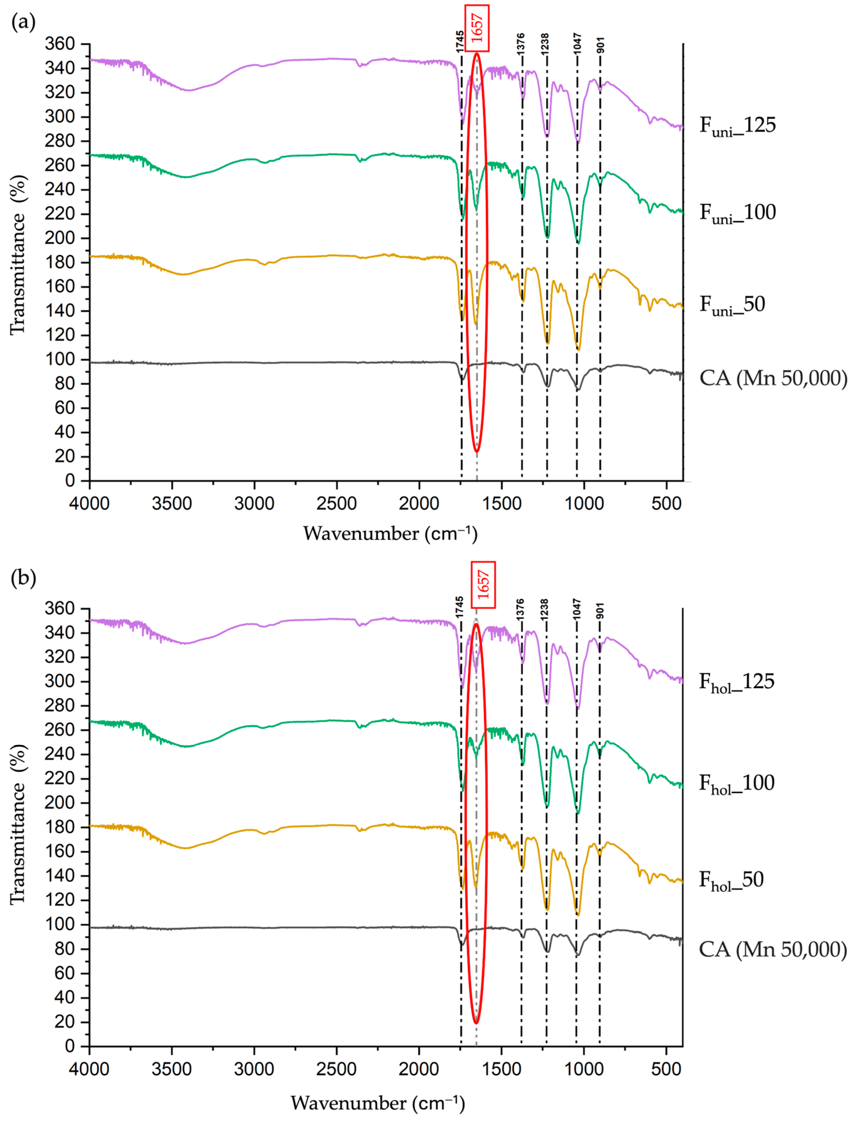
2.5.1. ATR-FTIR

The ATR-FTIR test was performed at two crucial moments in this study. First, it was used to evaluate the chemical composition of Funi and Fhol, investigating the structural changes caused by the DMF present in the fibres. The focus was on calculating the area index of characteristic functional groups, which allowed for determining the ideal size for the coagulation bath in the following steps. Subsequently, ATR-FTIR was used to analyse the PCFs’ chemical composition and surface and identify the presence of PEGs in the fibre’s core through their characteristic peaks. The analyses were performed on the ATR-FTIR IRAffinity-1S equipment (Shimadzu, Kyoto, Japan), equipped with a diamond crystal coupled to a HATR 10 accessory. The transmittance spectra were obtained in the wavenumber range between 400 and 4000 cm⁻1, with a resolution of 2 cm⁻1 and a scanning number of 200.

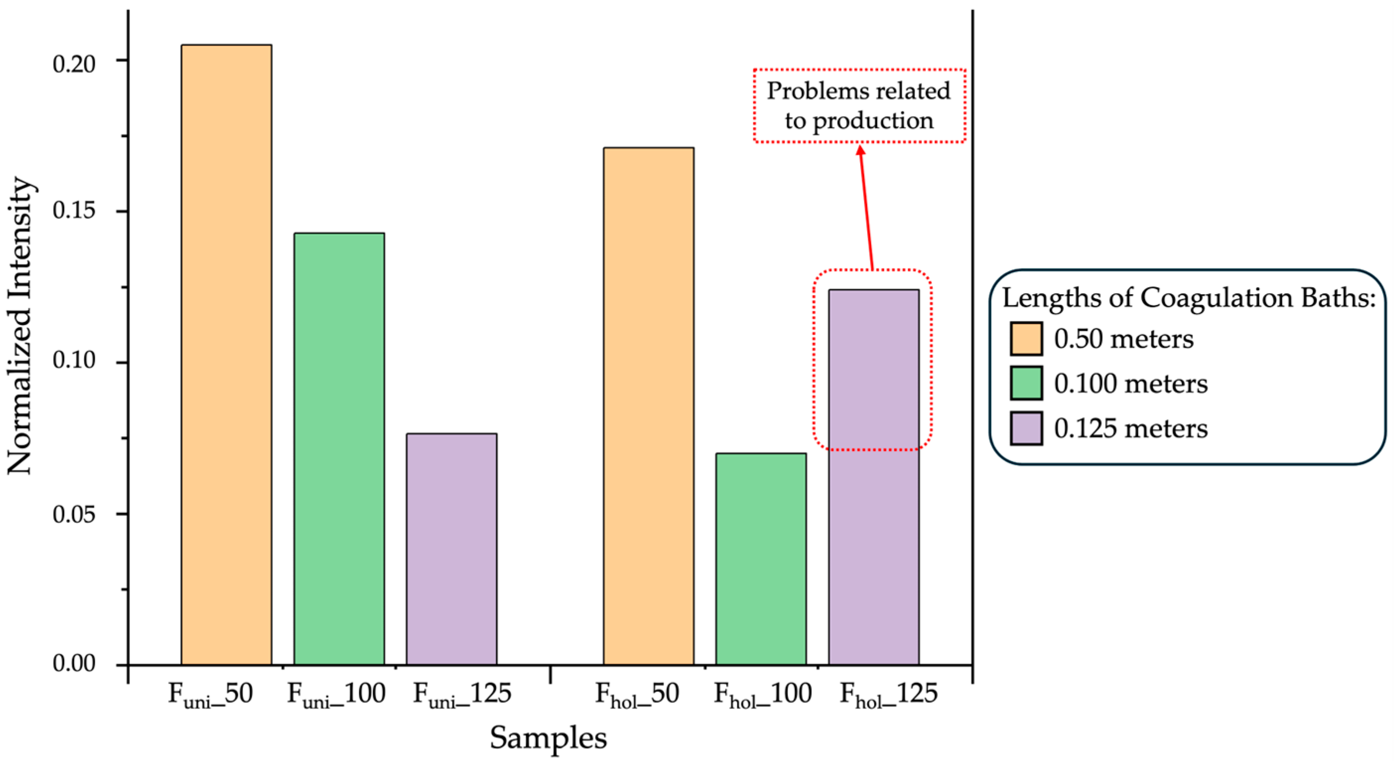
2.5.2. Index of Functional Group

The characteristic peaks of the ATR-FTIR transmittance spectra for CA and DMF were identified for each Funi and Fhol sample to calculate the area index [26,27]. The analyses prioritised the areas rather than the band heights. Specifically, the functional and structural indices were determined based on the calculated valley-to-valley band areas using the ratio between the area of the DMF peak (1657 cm⁻1), represented by A(1657) corresponding to the carbonyl area peak (AC=O) and all the characteristic peaks in the spectrum. These area peaks included the area of the DMF peak and the area of all the CA peaks, represented by ∑A. This process is described in Equations (1) and (2):
I F u n c t i o n a l ( D M F ) : = A C = O A ,
I C a r b o n y l ( D M F ) : = A ( 1657 ) A ,
where the following is true:
A = A 1745 + A 1657 + A 1376 + A 1238 + A 1047 + A 901

2.6. Bright-Field Microscopy

A Leica DM IL LED Bright-field microscope (Leica Microsystems, Weetzlar, Germany) was used to observe the morphology and uniformity of the four PCFs with a magnification of 5×.

2.7. Thermal Analysis

2.7.1. Thermogravimetric Analysis (TGA)

To confirm the thermal properties of the four PCFs studied, TGA was performed to analyse the mass loss until complete degradation, comparing the pristine materials (CA and PEGs) with the PCFs. The tests were conducted using the Hitachi STA 7200 equipment (Fukuoka, Japan). As a reference, an empty platinum crucible was used, while the samples were placed in separate platinum crucibles (Mettler Toledo, ME-26763, Columbus, OH, USA). During the tests, the samples were subjected to a nitrogen (N2) atmosphere with a calibrated flow of 200 mL/min, heating in a temperature range of 30 °C to 500 °C and exposed to a heating rate of 10 °C/min.

2.7.2. Differential Scanning Calorimetry (DSC)

To evaluate the behaviour of the melting/crystallisation phase change temperatures, melting/crystallisation enthalpy of the four PCF samples and to verify the phase change temperature, endothermic/exothermic changes of the four PCFs in comparison with the pristine materials PEGs (600 and 1000), cyclic DSC analyses were performed. The tests were conducted using the Mettler Toledo equipment, model DSC-822 (Columbus, OH, USA), with a cooling accessory (Labplant RP-60 cryostat, Huddersfield, UK). As a reference, an empty aluminium crucible was used, while the samples were placed in separate aluminium crucibles (40 μL) (Mettler Toledo, ME-26763, Columbus, OH, USA). During the tests, the samples were subjected to an argon (Ar) atmosphere with a calibrated flow rate of 50 mL/min, heating and cooling at a temperature range of 80 °C to −30 °C, and exposed to a heating/cooling rate of 10 °C/min.

3. Results

3.1. Evaluation of the Coagulation Bath

3.1.1. Influence of Different Lengths

Three Funi and three Fhol composed of CA were initially produced in coagulation baths of different lengths (0.50, 1.00, 1.25 m), using dH2O as the coagulation medium. This stage aimed to optimise the production of PCFs, focusing on the efficient removal of the DMF solvent and the uniform formation of the protective CA sheath. As DMF has toxic properties, its reduction is essential [23]. dH2O acts as an extraction agent, promoting solvent exchange due to the solubility of DMF in the aqueous medium. Longer coagulation baths theoretically allow more time for DMF extraction and better coagulation of the protective CA sheath, allowing the formation of uniform fibres all the way to the collector [28]. During the production of Funi and Fhol in the three sizes of coagulation bath studied, Funi showed no production difficulties. However, Fhol showed greater difficulty in maintaining its structural cohesion in the longest bath (1.25 m). This problem for Fhol may be directly related to the longer exposure time to the liquid medium (dH2O) in longer baths, which provides more time and opportunity for solvent exchange with the coagulant. In this case, the CA sheath begins to solidify in contact with the dH2O, while the core, also composed of dH2O, remains in a liquid state. In other words, this longer exchange time can lead to rapid removal of the liquid core, compromising the structural stability of the fibre and increasing the probability of collapse.
Zixuan Niu et al. [18] studied the possibility of an excessive exchange of the DMF solvent for the coagulant (dH2O), which may cause an increase in tensions between the solidified sheath and the liquid core. Furthermore, in very long coagulation baths, the problem of the exchange of DMF for the coagulant dH2O may lead to an uneven uniformity gradient along the length of the Fhol, resulting in a fragile, heterogeneous structure susceptible to rupture [28].

3.1.2. Area Index of Functional Group

After the fibres were produced in the three different systems, the DMF peak was evaluated using the ATR-FTIR test (Figure 4a,b). This test allowed the behaviour of the area of the characteristic DMF peak corresponding to the carbonyl functional group (C=O) to be observed [29]. It provided the respective data necessary to calculate the index.
The bar graph in Figure 5 represents the index calculated for the fibres (Funi_50, Funi_100 and Funi_125) and (Fhol_50, Fhol_100 and Fhol_125) produced in the different coagulation baths.
The study of the carbonyl functional group indices highlighted the influence of the coagulation size on the removal of the toxic solvent DMF and, consequently, on the efficient coagulation of CA in the fibres.
In the index calculated for the Funi, there was a considerable decrease in the amount of DMF as the length of the coagulation bath increased, presenting a higher index value for the initial bath of 0.50 m and a lower value for the bath of 1.25 m. This progressive decrease may be related to the fact that a uniaxial fibre, without a core, has a homogeneous structure, which allows more efficient evaporation of DMF in more extended coagulation baths since the entire surface of the Funi is in direct contact with dH2O for longer [30,31].
On the other hand, the indices calculated for Fhol showed a significant decrease in the amount of DMF when comparing the 0.50-metre and 1.00-metre coagulation baths. However, for the 1.25-metre bath, the DMF index was slightly higher than for the 1.00 metre bath, indicating a possible change in the extraction equilibrium. This increase in the DMF index is related to the difficulty in handling these Fhol to the collector, where they broke and were not uniform. This proves the fact discussed earlier that those co-axial fibres, with the presence of a core in the liquid state, break in larger coagulation baths due to a lack of structural cohesion [32]. This collapse may be related to problems of osmosis or diffusion of the DMF, since inside the fibres there must be a higher concentration of solvent molecules, and resistance to their escape can cause internal pressure. This dynamic can generate internal tensions, which compromise the uniformity and cohesion of the structure along the fibre produced [18,30].
Therefore, regarding the initial objective of identifying the appropriate coagulation size to produce PCF, it was possible to conclude that a medium coagulation bath, that is, 1.00 metre, was the most adequate among those tested, as it showed a significant reduction in DMF, uniform fibres, and ideal morphology.

3.2. Morphology of PCFs

After optimising the ideal size for the coagulation bath (dH2O), the next step was to produce four different PCFs incorporating PEGs (600 and 1000) into the core. The four PCFs were subjected to Bright-field microscopy analysis to evaluate the morphology and uniformity of the core-sheath structure. Figure 6 shows the morphologies, considering both the PEG variation and the ejection speed in the core.
In a study by Huang et al. [33], co-axial fibres containing PEG encapsulated in a polymer, forming a core-shell structure, showed a well-defined morphology and efficient encapsulation. When analysing the micrographs presented in Figure 6, an initial observation is that the cores formed are narrow. Although the ejection speed of the PEGs does not directly influence the formation of the core size of the PCFs, this behaviour may be related to the configuration of the needle (co-axial) used during production, which has a calibre of 11 G for the ejection of the CA (Mn 50,000) and 21 G for the PEGs (600 and 1000). It is known that co-axial needles with larger calibre numbers have narrower diameters, which explains the formation of smaller cores. In addition, these dimensions may favour interactions and molecular bonds between the solutions since they have similar functional groups [26], allowing PEG to be incorporated into the CA since the higher molecular weight (Mn) of the CA contributes to its expansion [14].
In addition, it was observed that the core formed by the two PEGs was well-defined and visible despite having narrow dimensions. This can be explained by the solubility of PEGs in dH2O in contrast to the insolubility of CA in the same aqueous medium. Rapid coagulation occurs when the CA solution comes into contact with the coagulation bath composed of dH2O, forming a protective sheath [26].
Finally, a striking feature of the PCFs was their flattened structure. This may be attributable to the low viscosity of the CA polymer solution due to its low concentration (10 wt.%). In addition, as mentioned above, molecular interactions can occur between the CA and PEG solutions, and due to the solubility of PEG in dH2O, some of it can be lost by diffusion. In comparison, as reported in the literature, PCFs produced with CA solutions of higher concentration and viscosity tend to exhibit a rounder and thicker morphology [14,26,34].

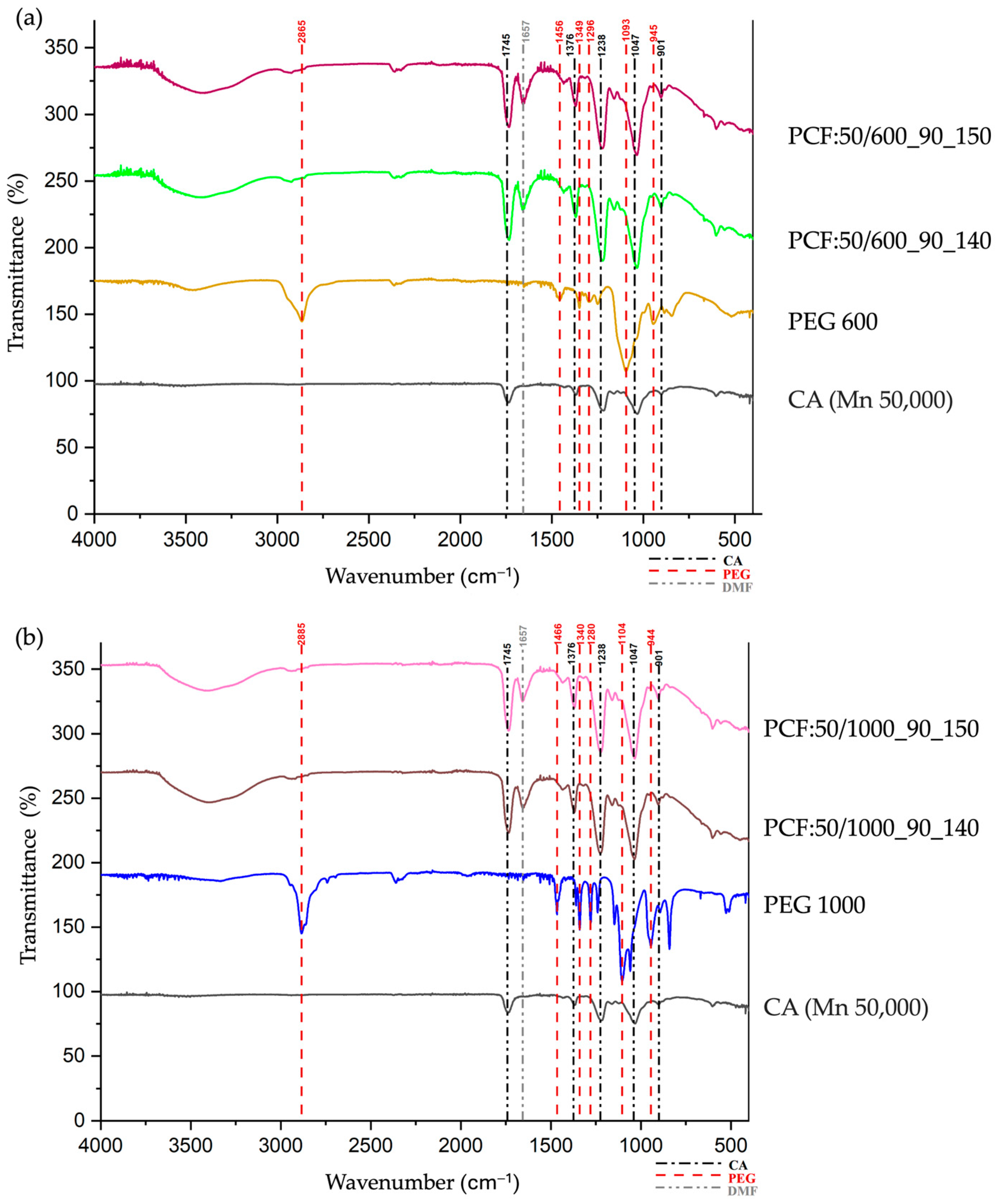
3.3. Chemical Analyses

The FTIR spectra analysis was performed to evaluate the effectiveness of the production process with the optimised coagulation bath, especially the reduction of the DMF solvent, and to confirm the presence of PEGs in the core of the well-defined core-sheath structures. Thus, through the transmittance spectra of the four PCFs compared to the pristine materials (Figure 7a,b), it was possible to identify the functional groups characteristic of each component.
The characteristic peaks related to the pristine CA were observed in all PCFs. The peak at ~1745 cm⁻1, attributed to the stretching of the carbonyl (C=O), indicates that the protective sheath was successfully precipitated, preserving the chemical properties of the CA during the production process [35]. Additionally, the peak at ~1238 cm⁻1, responsible for the elongation of the ester bond in the CA molecule (C-O-C), reinforces the conclusion that the polymer has not disintegrated, which is essential for the efficient encapsulation of the core [36]. The peaks at ~1047 cm⁻1 and ~901 cm⁻1 confirm the post-fabrication structural integrity of the fibre [14] through the presence of typical C-O stretching vibrations found in cellulose derivatives and the out-of-plane vibration of the glycosidic ring, consolidating the polysaccharide character of the fibre, respectively [37]. Therefore, the maintenance of CA peaks in PCFs, with consistent intensities, may suggest that the sheath was formed to protect the core.
Regarding the primary analysis, referring to the presence of PEGs in the PCF core, the peaks at ~2885 cm⁻1 and ~1456 cm⁻1 are associated with stretching and deformation of the C-H bonds in methylene groups (-CH2-) [38,39], which confirms the presence of PEGs (600 and 1000) in the encapsulated core. The peaks at ~1296 cm⁻1 and ~1093 cm⁻1 correspond to the stretching of the C-O-C ether bond chains [38,39]. The definition of these peaks may suggest that the core was formed efficiently, but the repositioning observed in the peaks at 1456 cm⁻1 and 1340 cm⁻1 in the PCFs, compared to the pristine PEGs, may indicate molecular interactions between the core and the protective sheath. These possible interactions may justify the reduced diameter of the core observed in the micrographs of the PCFs produced. The peak at ~945 cm⁻1 is associated with an out-of-plane C-H deformation represented by the movement of the PEG polymer chains [39]. The differences in intensity between the spectra of PCFs produced with PEGs (600 and 1000) can be attributed to their intrinsic characteristics, molecular mass, and viscosity [38,39]. These differences can impact the encapsulation efficiency.
Another essential aspect to be mentioned is that the decrease in the characteristic peak of the DMF solvent was evaluated at ~1657 cm⁻1, belonging to the carbonyl group (C=O) [29]. In other words, the PCF samples were produced in the optimised coagulation bath, significantly reducing this peak. Finally, the reduction in the DMF peak and the well-defined presence of the CA and PEGs peaks (600 and 1000) confirm the efficiency of the process and the formation of PCFs suitable for applications in civil engineering materials and thermoregulatory systems.

3.4. Thermal Analyses

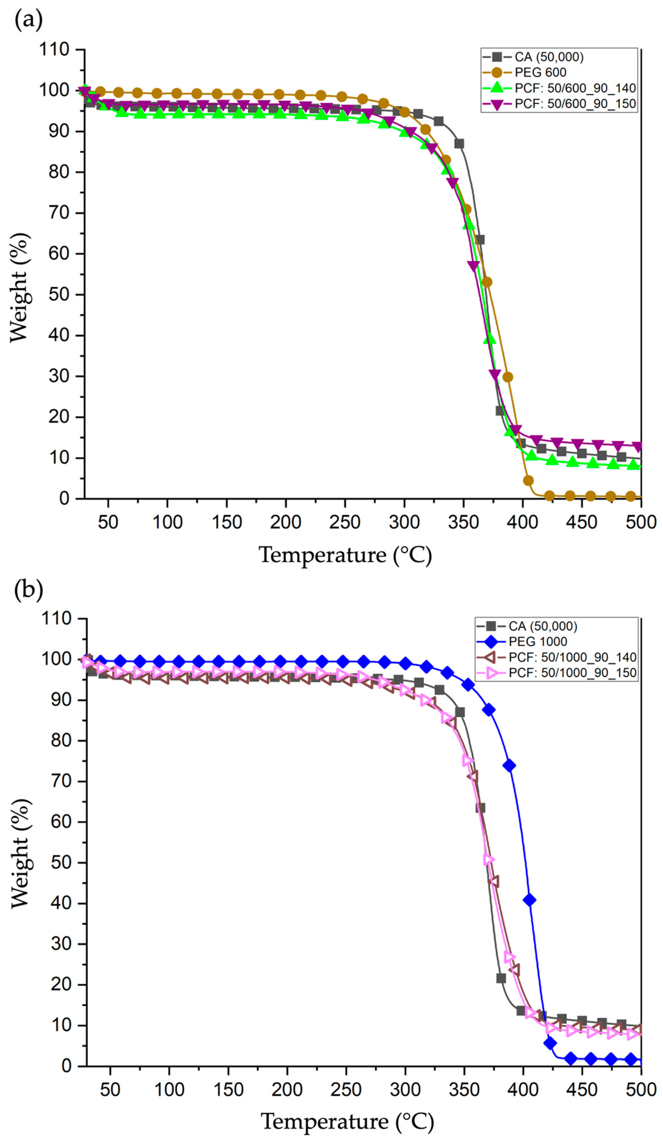
3.4.1. Thermogravimetric Analysis (TGA)

TGA was performed to evaluate the degradation temperature limits of pristine materials (CA, PEG 600 and 1000) and the PCFs produced to study and understand their thermal stability and suitability for applications in civil engineering construction materials. Although the temperatures analysed in this test exceed those typically found in built environments, it ensures that the PEG encapsulation process does not compromise the structural integrity of the PCFs at elevated temperatures. This is important for predicting the long-term stability of the materials.
CA presented a single-step degradation behaviour, i.e., with an initial mass loss at ~306 °C and finalised at ~390 °C, resulting in a well-defined and homogeneous polymeric structure [40]. PEG 600 registered an initial mass loss at ~272 °C, concluding its thermal degradation process at ~408 °C [41], while PEG 1000 began degrading at ~321 °C and ending it at ~425 °C [42]. This difference between the PEGs (600 and 1000) may be related to the difference in molecular weight. PEG 600 has a lower molecular weight and, consequently, shorter molecular chains, while PEG 1000 has a higher molecular weight, with longer polymer chains and more excellent crystallinity, which requires more energy and higher temperature to be decomposed [41,42].
The four PCFs (Figure 8a,b) exhibited a slight state of degradation around ~60 °C, which can be attributed to the elimination of residual molecules of the solvents present in the composition of the fibre sheath [14,43]. The two PCFs produced with PEG 600 in the core (PCF:50/600_90_140 and PCF:50/600_90_150) (Figure 8a) showed thermal degradation temperatures between ~264 °C and ~397 °C, values slightly lower than those presented for the pristine PEG 600 material (~272–408 °C). This slight can be explained by the partial interaction between the CA polymers and the PEGs and the possible partial hydrolysis of the ether bonds (C-O-C) [41]. Both molecular interaction and hydrolysis result in a lower energy required to initiate the thermal degradation process, as evidenced by the slightly lower temperatures at the onset of mass loss [44]. Despite this, the total degradation temperature range exceeded that of CA (~306–390 °C), evidencing that the CA sheath effectively protected the core containing PEG 600 during the thermal degradation.
On the other hand, PCFs with PEG 1000 (PCF:50/1000_90_140 and PCF:50/1000_90_150) (Figure 8b) showed higher thermal degradation temperatures between ~273 °C and ~413 °C, indicating a greater thermal stability of PEG 1000 compared woth PEG 600. This greater stability may be related to the higher molecular weight and longer polymer chains of PEG 1000, which result in a more organized polymer structure. Furthermore, this structural organisation can reduce the probability of unwanted chemical interactions between the core and the sheath, highlighting how the thermal behaviour of PCFs is influenced by the structural and chemical properties of the PEGs chosen for the core [39].
The ejection speed used for the PEGs did not significantly impact the thermal degradation results due to the slight variations between the tested values.
The thermal results obtained for the PCFs, especially the differences between PEG 600 and PEG 1000, show the relevance of these PCFs for practical applications in Civil Engineering construction materials. The degradation temperatures observed are above 250 °C for all PCFs, indicating that these samples have sufficient thermal stability to withstand the typical conditions of use in urban structures, such as concrete and pavements. In addition, this encapsulation of the core by the sheath ensures efficient thermal protection during exposure to high temperatures, which can prevent thermal losses and unwanted leaks.

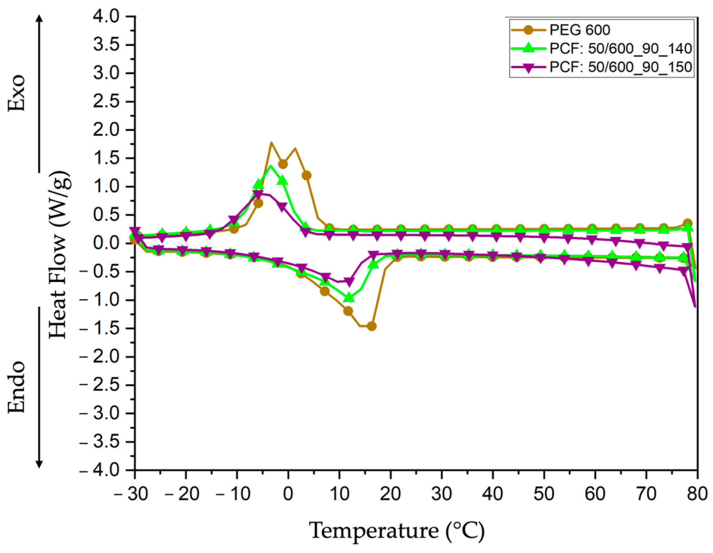
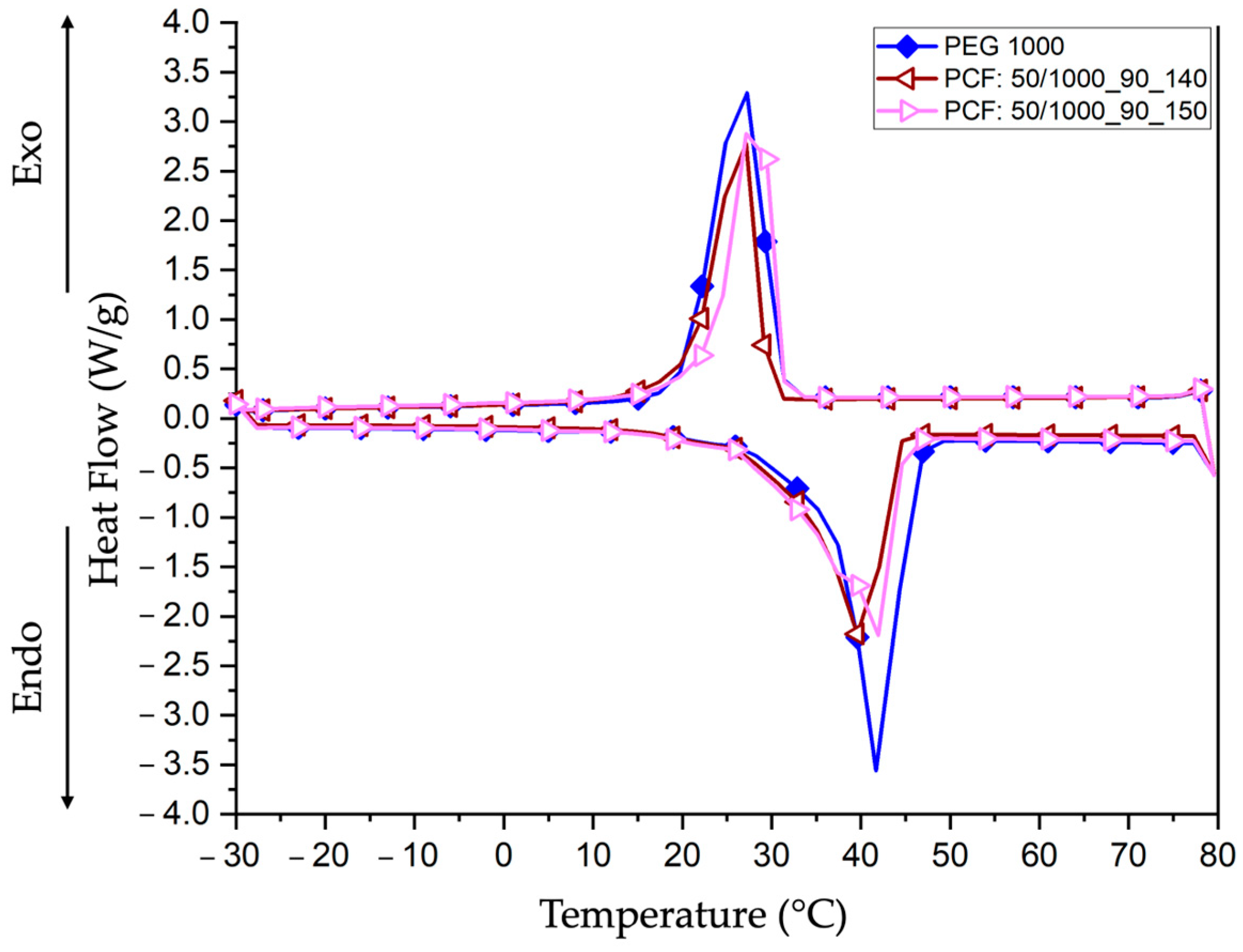
3.4.2. Differential Scanning Calorimetry (DSC)

Cyclic DSC analysis evaluated PCFs’ thermal properties and behaviour and compared the results to pristine materials (PEG 600 and 1000). This thermal analysis is essential for understanding the impact of PEG incorporation and the uniformity of PCF structuring on phase changes (melting and crystallisation), indicating their heat storage and release capacity.
Starting the analysis with the results for PEG 600 (Figure 9) and (Table 1), the pristine material presented a well-defined melting endothermic (endo) peak at 15.76 °C, with a melting enthalpy of 68.21 J/g, confirming its crystalline behaviour during melting [25,44]. The material (PEG 600) is particularly suitable for integration into cementitious materials, where it can increase indoor thermal comfort in buildings by attenuating temperature fluctuations in temperate and mild climates. When incorporated into building materials, PEG 600 can absorb excess heat during the day and release it at night, reducing the need for active cooling [44]. However, the PCFs incorporated with this PEG 600 (PCF:50/600_90_140 and PCF:50/600_90_150) showed a reduction in the endothermic (endo) melting temperatures to 12.64 °C and 11.04 °C, accompanied by lower enthalpy values, 39.24 J/g and 30.59 J/g, respectively. This reduction can be attributed to the PEG solution to form the core (concentration of 0.90 g/mL), using dH2O in the composition, which induces the presence of hydrogen bonds between the dH2O and PEG 600 molecules, decreasing the crystallinity of the material [45]. In the same line of reasoning, dH2O also acts as a plasticiser, increasing the mobility of the polymer chains and promoting a more amorphous behaviour of the material, which results in lower thermal stability and less energy required to carry out the fusion process. In the cooling phase, PEG 600 presented a crystallisation temperature of −1.21 °C with two peaks and an exothermic (exo) enthalpy of 72.74 J/g [46]. These two crystallisation peaks may indicate the formation of two crystalline phases or secondary recrystallisation due to PEG 600 having a semi-crystalline structure. However, the PCFs exhibited lower crystallisation temperatures, −3.78 °C and −5.30 °C, and enthalpies with lower values of 50.17 J/g and 40.93 J/g, respectively. This time, the reduction in crystallisation temperatures can be explained by supercooling, which occurs when the material cools below its melting temperature before forming crystals [47]. Therefore, the protective CA sheath contributes to this effect by restricting the PEG 600 core and limiting its mobility, making it difficult to organise the polymer chains into a well-defined crystalline structure [14].
Regarding the results for PEG 1000 (Figure 10) and (Table 2), the analyses showed an initial melting temperature of 41.24 °C and an enthalpy of 93.62 J/g, indicating a result with more excellent thermal stability compared with that presented for PEG 600 due to its larger polymer chains and crystallinity [25,44]. The PCFs with PEG 1000 (PCF: 50/1000_90_140 and PCF: 50/1000_90_150) exhibited melting temperatures of 40.32 °C and 41.13 °C and enthalpies of 83.47 J/g and 88.88 J/g, respectively. Although the melting temperatures suffered a slight decrease, the influence of dH2O will be minor for the crystalline structure of PEG 1000 because the material presents longer and more stable polymer chains, which result in enthalpy values relatively close to those of the pristine material [39]. In the cooling phase, PEG 1000 presented a crystallisation temperature of 26.59 °C and an exothermic (exo) enthalpy of 112.96 J/g [25]. Meanwhile, the PCFs exhibited slightly higher crystallisation temperatures of 26.95 °C and 28.35 °C, with enthalpies of 84.66 J/g and 88.79 J/g, respectively. This behaviour can be attributed to the encapsulation process of PEG 1000 in these PCFs, stabilising the nucleation and alignment of the PEG polymer chains, resulting in a slight increase in the crystallisation temperature [48].
The results presented for the DSC test are connected to those presented for the TGA test since both reinforce the influence of dH2O on the thermal stability of the PCFs and their encapsulation. While the TGA test demonstrated a reduction in the degradation temperatures of the encapsulated PEGs, the DSC test directly impacted the heat storage capacity due to the decrease in crystallinity and enthalpy in the respective PCFs. However, the protection that the CA sheath provides is sufficient to preserve the thermoregulatory characteristics of the PEGs. Therefore, these thermoregulatory characteristics of the PEGs incorporated in the PCFs highlight their potential applications. For example, PCFs with PEG 600, with lower melting and crystallisation temperatures, are suitable for regions with moderate climates since they can release heat at lower temperatures, providing continuous thermal regulation at night. Meanwhile, PCFs with PEG 1000, with more excellent thermal and enthalpy stability, for example, show promising performance for regions with higher temperatures, where the ability to store heat for extended periods is required.
Compared with the study by Cao et al. [34], the encapsulation of PEG within co-axial fibres resulted in a significant improvement in thermal stability, as observed in the DSC test. The PCFs presented well-defined phase transitions and high enthalpies of fusion and crystallisation, reducing the supercooling effect and ensuring efficient heat storage and release throughout the thermal cycle. Therefore, these results corroborate the findings in the literature, evidencing that the core-shell structure plays an essential role in the thermal stabilisation of PEGS and their viability for civil engineering applications.

4. Conclusions

This study optimised the coagulation bath size for producing co-axial Phase Change Fibres (PCFs), ensuring their structural, chemical, and thermal performance. The ATR-FTIR area index analysis of uniaxial (Funi) and hollow (Fhol) fibres confirmed that longer coagulation baths enhanced DMF solvent removal. However, excessive bath lengths (1.25 m) induced structural stress in hollow fibres, compromising integrity. An optimal bath length of 1.00 m was identified to balance efficient solvent removal and fibre stability.
Morphological analysis confirmed the successful encapsulation of PEG cores within the CA sheath, with homogeneous core-sheath structures observed in all PCFs. ATR-FTIR further verified the significant reduction in DMF, demonstrating the efficiency of the optimised coagulation bath in improving fibre quality.
Thermal analyses (TGA and DSC) revealed that PCFs maintained thermal stability at temperatures between ~264 °C and ~397 °C for PEG 600-based fibres and ~273 °C and ~413 °C for PEG 1000-based fibres. DSC results confirmed that PEG 600-based PCFs exhibited melting temperatures of ~12.64 °C and ~11.04 °C, while PEG 1000-based PCFs showed values of ~40.32 °C and ~41.13 °C, validating their phase change behaviour. These findings suggest that PCFs with PEG 600 are suitable for mild climates, while PCFs with PEG 1000 are better suited for high-temperature applications due to their greater thermal stability.
These results reinforce the potential of PCFs for thermoregulation in civil engineering applications, where their thermal properties allow them to adapt to different climatic conditions. For optimal performance, the selection and optimisation of PCFs must consider structural demands and climatic conditions. In tropical regions, they limit heat absorption during the day and release it at night, mitigating the Urban Heat Island (UHI) effect and improving energy efficiency. They function as thermal regulators in colder climates, reducing heat loss and heating demands. Furthermore, the thermal stability demonstrated by TGA and DSC analyses confirms their long-term reliability for applications such as thermoregulated cement mortars.
An important aspect to be investigated is the potential to increase the mechanical strength of composite materials since the sheath-core structure improves durability and resistance to thermal and mechanical stresses. Therefore, future research should prioritize mechanical performance assessments, including Dynamic Mechanical Analysis (DMA) and tensile testing, to validate structural resilience under real-world conditions. In addition, Energy Dispersive Spectroscopy (EDS) and Surface Plasmon Resonance (SPR) could further investigate the potential molecular interactions between CA and PEG. SPR, in particular, can provide valuable insights into the bonding dynamics of these materials. Finally, integrating PCFs into cementitious materials and evaluating their performance in simulated urban environments will be essential for confirming their practical applicability in sustainable construction.

Author Contributions

Conceptualisation, N.H.; methodology, I.R.S. and H.P.F.; software, N.H., J.M. and M.M.S.; validation, J.C.; formal analysis, N.H., I.R.S. and H.P.F.; research, N.H., I.R.S. and J.C.; resources, M.M.S., M.F.M.C. and J.C.; data curation, N.H. and M.F.M.C.; preparation of the original draft, N.H.; revision and editing of the writing, J.M., I.R.S., H.P.F., M.M.S., M.F.M.C. and J.C.; visualisation, I.R.S. and H.P.F.; supervision, I.R.S., H.P.F., M.F.M.C. and J.C.; project administration, M.F.M.C. and J.C.; acquisition of funding, M.F.M.C. and J.C.; All authors have read and agreed to the published version of the manuscript.

Funding

This research was funded by the Foundation for Science and Technology FCT/MCTES through national funds (PIDDAC) under the projects NanoAir PTDC/FISMAC/6606/2020 (doi.org/10.54499/PTDC/FIS-MAC/6606/2020), (RE)NERGY-BUILD 2023.14962.PEX, UIDB/04650 Centre of Physics of Minho and Porto Universities (CF-UM-UP), UID/CTM/00264/2020 and UID/QUI/00686/2020. N.H., I.R.S., and H.P.F. would like to thank FCT for funding under reference 2024.01990.BD, 2022.00763.CEECIND (doi.org10.54499/2022.00763.CEECIND/CP1718/CT0006), and 2021.02720.CEECIND (doi.org/10.54499/DL57/2016/CP1377/CT0098), respectively.

Institutional Review Board Statement

Not applicable.

Informed Consent Statement

Not applicable.

Data Availability Statement

The original contributions presented in the study are included in the article; further inquiries can be directed to the corresponding authors.

Conflicts of Interest

The authors declare no conflicts of interest.

Abbreviations

The following abbreviations are used in this manuscript:
UHIUrban Heat Island
PCMPhase Change Materials
PCFPhase Change Fibres
PEGPolyethylene glycol
ATR-FTIRAttenuated Total Reflectance-Fourier Transform Infrared Spectroscopy
TGAThermogravimetric Analysis
DSCDifferential Scanning Calorimetry
LHTSLatent heat storage materials
DMFDimethylformamide
CACellulose Acetate
dH2ODistilled water
RTRoom temperature
FuniUniaxial fibres
FholHollow fibres
MnMolecular weight
EndoEndothermic
ExoExothermic

References

  1. Rajagopal, P.; Priya, R.S.; Senthil, R. A review of recent developments in the impact of environmental measures on urban heat island. Sustain. Cities Soc. 2023, 88, 104279. [Google Scholar] [CrossRef]
  2. Piracha, A.; Chaudhary, M.T. Urban Air Pollution, Urban Heat Island and Human Health: A Review of the Literature. Sustainability 2022, 14, 9234. [Google Scholar] [CrossRef]
  3. Segundo, I.R.; Freitas, E.; Branco, V.C.; Landi, S.; Costa, M.; Carneiro, J. Review and analysis of advances in functionalized, smart, and multifunctional asphalt mixtures. Renew. Sustain. Energy Rev. 2021, 151, 111552. [Google Scholar] [CrossRef]
  4. Kim, E.S.; Bae, C.; Ko, S.Y.; Won, J.E.; Lee, J.H.; Paio, Y.; Lee, D.K. Enhancing the effectiveness of heat adaptation strategies through citizen science-based outdoor thermal comfort. Heliyon 2024, 10, e39413. [Google Scholar] [CrossRef] [PubMed]
  5. Riahi, A.; Shafii, M.B. Experimental Evaluation of a Vapor Compression Cycle Integrated With a Phase Change Material Storage Tank for Peak Load Shaving. Eng. Sci. 2023, 23, 870. [Google Scholar] [CrossRef]
  6. Matos, A.M.; Delgado, J.M.P.Q.; Guimarães, A.S. Linking Energy Poverty with Thermal Building Regulations and Energy Efficiency Policies in Portugal. Energies 2022, 15, 329. [Google Scholar] [CrossRef]
  7. Gogoi, M.; Das, B.; Patowari, P.K. Characterization and performance analysis of modified phase change material with paraffin wax and waste exhaust carbon particles for thermal energy storage. J. Energy Storage 2025, 108, 115068. [Google Scholar] [CrossRef]
  8. Pinheiro, C.; Landi, S.; Lima, O.; Ribas, L.; Hammes, N.; Segundo, I.R.; Homem, N.C.; Branco, V.C.; Freitas, E.; Costa, M.F.; et al. Advancements in Phase Change Materials in Asphalt Pavements for Mitigation of Urban Heat Island Effect: Bibliometric Analysis and Systematic Review. Sensors 2023, 23, 7741. [Google Scholar] [CrossRef]
  9. Varadharajan, S.; Vasanthan, K.S.; Verma, S. Recent development in nano-phase change materials and their applications in enhancing thermal capacity of intelligent buildings: A state-of-the art review. J. Mater. Res. 2023, 38, 1463–1487. [Google Scholar] [CrossRef]
  10. Asadi, I.; Ji, G.; Steiner, G.; Baghban, M.H. Impact of microencapsulated phase change materials (PCMs) on the thermal and mechanical performance of cement mortar. Dev. Built Environ. 2024, 21, 100594. [Google Scholar] [CrossRef]
  11. Wang, X.; Ma, B.; Li, S.; Si, W.; Wei, K.; Zhang, H.; Zhou, X.; Fang, Y.; Kang, X.; Shi, W. Review on application of phase change materials in asphalt pavement. J. Traffic Transp. Eng. (Engl. Ed.) 2023, 10, 185–229. [Google Scholar] [CrossRef]
  12. Zhang, M.; Zheng, Y.; He, Y.; Jin, Z.; Zhang, Y.; Shi, L. Novel modular PCM wall board for building heating energy efficiency: Material preparation, manufacture and dynamic thermal testing. Appl. Therm. Eng. 2024, 256, 124168. [Google Scholar] [CrossRef]
  13. Drissi, S.; Ling, T.-C.; Mo, K.H. Development of leak-free phase change material aggregates. Constr. Build. Mater. 2020, 230, 117029. [Google Scholar] [CrossRef]
  14. Hammes, N.; Pinheiro, C.; Segundo, I.R.; Homem, N.C.; Silva, M.M.; Felgueiras, H.P.; Soares, G.M.B.; Freitas, E.; Costa, M.F.M.; Carneiro, J.A.O. Coaxial Fibres Incorporated with Phase Change Materials for Thermoregulation Applications. Appl. Sci. 2024, 14, 2473. [Google Scholar] [CrossRef]
  15. Miranda, C.S.; Marinho, E.; Seabra, C.L.; Evenou, C.; Lamartine, J.; Fromy, B.; Costa, S.P.; Homem, N.C.; Felgueiras, H.P.; Amorim, M. Antimicrobial, antioxidant and cytocompatible coaxial wet-spun fibers made of polycaprolactone and cellulose acetate loaded with essential oils for wound care. Int. J. Biol. Macromol. 2024, 277, 134565. [Google Scholar] [CrossRef] [PubMed]
  16. Li, X.; Li, Q.; Hu, J.; Li, R.; Lin, J.; Liu, Y. Core-sheath phase change fibers via coaxial wet spinning for solar energy active storage. Compos. Part B Eng. 2022, 247, 110346. [Google Scholar] [CrossRef]
  17. Ahn, Y.-H.; DeWitt, S.J.A.; McGuire, S.; Lively, R.P. Incorporation of Phase Change Materials into Fibers for Sustainable Thermal Energy Storage. Ind. Eng. Chem. Res. 2021, 60, 3374–3384. [Google Scholar] [CrossRef]
  18. Niu, Z.; Qi, S.; Shuaib, S.S.A.; Züttel, A.; Yuan, W. Flexible core-sheath thermochromic phase change fibers for temperature management and electrical/solar energy harvesting. Compos. Sci. Technol. 2022, 226, 109538. [Google Scholar] [CrossRef]
  19. Radishevskii, M.B.; Serkov, A.T. Coagulation Mechanism in Wet Spinning of Fibres. Fibre Chem. 2005, 37, 266–271. [Google Scholar] [CrossRef]
  20. Jeong, Y.H.; Im, J.; Lee, D.-M.; Kim, M.C.; Oh, D.; Son, J.; Park, S.; Hyun, K.; Jeong, B.; Lee, J. Coagulation engineering of surfactant-based wet spinning of carbon nanotube fibers. Carbon Lett. 2024, 34, 1803–1815. [Google Scholar] [CrossRef]
  21. Aneem, T.; Wong, S.; Afrin, H.; Nurunnabi, M.; Li, X.; Arafat, M. Investigation of coagulation process of wet-spun sodium alginate polymannuronate fibers with varied functionality using organic coagulants and cross-linkers. Mater. Today Chem. 2021, 22, 100580. [Google Scholar] [CrossRef]
  22. Pagliero, M.; Khayet, M.; García-Payo, C.; García-Fernández, L. Hollow fibre polymeric membranes for desalination by membrane distillation technology: A review of different morphological structures and key strategic improvements. Desalination 2021, 516, 115235. [Google Scholar] [CrossRef]
  23. Pereira, C.; Pinto, T.V.; Santos, R.M.; Correia, N. Sustainable and Naturally Derived Wet Spun Fibers: A Systematic Literature Review. Fibers 2024, 12, 75. [Google Scholar] [CrossRef]
  24. Pérez-Silva, I.; Canales-Feliciano, G.D.; Rodríguez, J.A.; Mendoza-Huizar, L.H.; Pérez-Estrada, S.; Ibarra, I.S.; Páez-Hernández, M.E. The Evaluation of Cellulose Acetate Capsules Functionalized for the Removal of Cd(II). Polymers 2023, 15, 3917. [Google Scholar] [CrossRef] [PubMed]
  25. Paberit, R.; Rilby, E.; Göhl, J.; Swenson, J.; Refaa, Z.; Johansson, P.; Jansson, H. Cycling Stability of Poly(ethylene glycol) of Six Molecular Weights: Influence of Thermal Conditions for Energy Applications. ACS Appl. Energy Mater. 2020, 3, 10578–10589. [Google Scholar] [CrossRef]
  26. Hammes, N.; Monteiro, J.; Pinheiro, C.; Felgueiras, H.P.; Soares, G.M.B.; Segundo, I.R.; Costa, M.F.M.; Carneiro, J. Exploring the Cutting Process of Coaxial Phase Change Fibers under Optical Characterization Tests. Appl. Sci. 2024, 14, 8050. [Google Scholar] [CrossRef]
  27. Segundo, I.R.; Landi, S.; Margaritis, A.; Pipintakos, G.; Freitas, E.; Vuye, C.; Blom, J.; Tytgat, T.; Denys, S.; Carneiro, J. Physicochemical and Rheological Properties of a Transparent Asphalt Binder Modified with Nano-TiO2. Nanomaterials 2020, 10, 2152. [Google Scholar] [CrossRef]
  28. Ratri, C.R.; Aguta, T.B.; Arundati, A.H.; Rohib, R.; Chalid, M.; Astutiningsih, S.; Nugraha, A.F. Effect of Coagulation Bath Composition on Cellulose-Based Polymer Electrolyte Fabricated via Non-Solvent-Induced Phase Separation Method. Int. J. Technol. 2023, 14, 1605–1614. [Google Scholar] [CrossRef]
  29. Lin, L.; Liu, C.; Sacci, R.L.; Chen, X.C.; Doughty, B. Molecular structures of residual solvent in polyacrylonitrile based electrolytes: Implications for conductivity and stability. J. Chem. Phys. 2024, 161, 233578. [Google Scholar] [CrossRef]
  30. Nguyen, K.D. Temperature Effect of Water Coagulation Bath on Chitin Fiber Prepared through Wet-Spinning Process. Polymers 2021, 13, 1909. [Google Scholar] [CrossRef]
  31. Kulichikhin, V.; Makarov, I.; Mironova, M.; Golova, L.; Vinogradov, M.; Shandryuk, G.; Levin, I.; Arkharova, N. A Role of Coagulant in Structure Formation of Fibers and Films Spun from Cellulose Solutions. Materials 2020, 13, 3495. [Google Scholar] [CrossRef] [PubMed]
  32. Sanahuja-Embuena, V.; Khensir, G.; Yusuf, M.; Andersen, M.F.; Nguyen, X.T.; Trzaskus, K.; Pinelo, M.; Helix-Nielsen, C. Role of Operating Conditions in a Pilot Scale Investigation of Hollow Fiber Forward Osmosis Membrane Modules. Membranes 2019, 9, 66. [Google Scholar] [CrossRef] [PubMed]
  33. Lin, J.; Huang, J.; Guo, Z.; Bin Xu, B.; Cao, Y.; Ren, J.; Hou, H.; Xiao, Y.; Elashiry, M.; El-Bahy, Z.M.; et al. Hydrophobic Multilayered PEG@PAN/MXene/PVDF@SiO2 Composite Film with Excellent Thermal Management and Electromagnetic Interference Shielding for Electronic Devices. Small 2024, 20, e2402938. [Google Scholar] [CrossRef]
  34. Cao, H.; Xu, Z.; Zhang, T.; Zhao, Y. Highly stretchable phase change fibers from coaxial wet spinning of nonaqueous emulsions for temperature regulation. Chem. Eng. J. 2023, 478, 147389. [Google Scholar] [CrossRef]
  35. Coelho, G.; Champion, D.; Heintz, O.; Krystianiak, A.; Debon, S.; Deleris, I.; Wallecan, J.; Roudaut, G. Impact of processing and storage on citrus fiber functionality: Insights from spectroscopic techniques. Int. J. Biol. Macromol. 2024, 282, 137281. [Google Scholar] [CrossRef]
  36. Sukmawan, R.; Kusmono; Wildan, M.W. Study of alkali and acetylation treatments on sisal fibers compatibility with low-amine/epoxy stoichiometric ratio. Results Eng. 2024, 24, 103127. [Google Scholar] [CrossRef]
  37. Zhuang, J.; Li, M.; Pu, Y.; Ragauskas, A.J.; Yoo, C.G. Observation of Potential Contaminants in Processed Biomass Using Fourier Transform Infrared Spectroscopy. Appl. Sci. 2020, 10, 4345. [Google Scholar] [CrossRef]
  38. Caccamo, M.T.; Magazù, S. Ethylene Glycol—Polyethylene Glycol (EG-PEG) Mixtures: Infrared Spectra Wavelet Cross-Correlation Analysis. Appl. Spectrosc. 2017, 71, 401–409. [Google Scholar] [CrossRef]
  39. Yacob, N.; Yusof, M.R.; Mahmud, M.; Mohamed, A.Z.; Badri, K.H. Effect of Different Molecular Weight and Concentration of Polyethylene Glycol (PEG) on Tensile and Morphology of Sago Starch Film. ASM Sci. J. 2021, 16, 1–10. [Google Scholar] [CrossRef]
  40. Teixeira, S.C.; de Oliveira, T.V.; Fortes-Da-Silva, P.; Raymundo-Pereira, P.A.; Ribeiro, A.R.C.; Batista, L.F.; Gomes, N.O.; Stringheta, P.C.; Soares, N.d.F.F. Investigation of the influence of plasticizers on the biodegradability of cellulose acetate. J. Appl. Polym. Sci. 2023, 140, 54316. [Google Scholar] [CrossRef]
  41. Sadeghpour, M.; Yusoff, R.; Aroua, M.K.; Tabandeh, M. Modification of polyethylene glycol with choline chloride and evaluation of the CO2 absorption capacity of their aqueous solutions. Greenh. Gases Sci. Technol. 2018, 8, 324–334. [Google Scholar] [CrossRef]
  42. Lascurain, P.G.G.; Frigione, M.; Sarcinella, A.; Linares, F.; Schröer, L.; Cnudde, V.; Toniolo, L.; Goidanich, S. Improving PEG confinement in smart aggregates for lime-based mortars. Constr. Build. Mater. 2024, 454, 138996. [Google Scholar] [CrossRef]
  43. Prasad, N.S.; Babarao, R.; Madapusi, S.; Sridhar, S.; Choudhury, N.R.; Bhargava, S.K. Residual solvent induced physical morphology and gas permeation in polyamide-imide membrane: Experimental investigation and molecular simulations. Eur. Polym. J. 2022, 165, 111012. [Google Scholar] [CrossRef]
  44. Minea, A.A. State of the Art in PEG-Based Heat Transfer Fluids and Their Suspensions with Nanoparticles. Nanomaterials 2021, 11, 86. [Google Scholar] [CrossRef] [PubMed]
  45. Yuan, Y.; Zhang, H.; Zhang, N.; Sun, Q.; Cao, X. Effect of water content on the phase transition temperature, latent heat and water uptake of PEG polymers acting as endothermal-hydroscopic materials. J. Therm. Anal. Calorim. 2016, 126, 699–708. [Google Scholar] [CrossRef]
  46. Noel, J.; Jannot, Y.; Métivier, C.; Sgreva, N.R. Thermal characterization of polyethylene glycol 600 in liquid and solid phase and across the phase transition. Thermochim. Acta 2022, 716, 179326. [Google Scholar] [CrossRef]
  47. Hu, Y.; Liao, Y.; Zheng, Y.; Ikeda, K.; Okabe, R.; Wu, R.; Ozaki, R.; Xu, J.; Xu, Q. Influence of Cooling Rate on Crystallization Behavior of Semi-Crystalline Polypropylene: Experiments and Mathematical Modeling. Polymers 2022, 14, 3646. [Google Scholar] [CrossRef]
  48. Yan, Y.; Li, W.; Zhu, R.; Lin, C.; Hufenus, R. Flexible Phase Change Material Fiber: A Simple Route to Thermal Energy Control Textiles. Materials 2021, 14, 401. [Google Scholar] [CrossRef]
Figure 1. Urban Heat Island (UHI) contribution and consequences.
Applsci 15 03028 g001
Figure 2. The schematic view of the co-axial setup for the wet-spinning process and the Phase Change Polymer Fibres (PCFs) composition.
Applsci 15 03028 g002
Figure 3. Representation of the three lengths used to study the coagulation bath (dH2O).
Applsci 15 03028 g003
Figure 4. Comparison of the characteristic peaks of DMF in the ATR-FTIR spectra for the three coagulation bath lengths (0.50, 1.00, and 1.25) m. (a) Funi_50, Funi_100 and Funi_125; (b) Fhol_50, Fhol_100 and Fhol_125.
Applsci 15 03028 g004
Figure 5. Comparison of the indices of the characteristic peaks of Funi and Fhol for the three coagulation bath lengths (0.50, 1.00, and 1.25) m.
Applsci 15 03028 g005
Figure 6. Micrographs of the morphology of PCFs obtained by Bright-field microscopy, with a magnification of 5×. (a) PCF:50/600_90_140; (b) PCF:50/600_90_150; (c) PCF:50/1000_90_140; (d) PCF:50/1000_90_150.
Applsci 15 03028 g006
Figure 7. ATR-FTIR spectra of the PCFs. (a) PCF:50/600_90_140, PCF:50/600_90_150, pristine materials CA (Mn 50,000), and PEG 600; (b) PCF:50/1000_90_140, PCF:50/1000_90_150, pristine materials CA (Mn 50,000), and PEG 1000.
Applsci 15 03028 g007
Figure 8. TGA curves were obtained from 30 °C to 500 °C under an N2 atmosphere, a calibrated flow rate of 200 mL/min and exposed to a heating rate of 10 °C/min. (a) Pristine materials (CA and PEG 600) and PCFs 600; (b) Pristine materials (CA and PEG 1000) and PCFs 1000.
Applsci 15 03028 g008
Figure 9. DSC curves of the pristine materials (CA and PEG 600) and PCFs 600, obtained from 80 to −30 °C under an Ar atmosphere, a calibrated flow rate of 50 mL/min, and exposed to a heating/cooling rate of 10 °C/min.
Applsci 15 03028 g009
Figure 10. DSC curves of the pristine materials (CA and PEG 1000) and PCFs 1000, obtained from 80 to −30 °C under an Ar atmosphere, a calibrated flow rate of 50 mL/min, and exposed to a heating/cooling rate of 10 °C/min.
Applsci 15 03028 g010
Table 1. Thermal properties of PEG 600 and four PCFs.
SamplesPeak Temperature
Onset
(°C)
Enthalpy
Endo
(J/g)
Peak Temperature
Endset
(°C)
Enthalpy
Exo
(J/g)
PEG 60015.7668.21−1.2172.74
PCF:50/600_90_14012.6439.24−3.7850.17
PCF:50/600_90_15011.0430.59−5.3040.93
Table 2. Thermal properties of PEG 1000 and four PCFs.
SamplesPeak Temperature
Onset
(°C)
Enthalpy
Endo
(J/g)
Peak Temperature
Endset
(°C)
Enthalpy
Exo
(J/g)
PEG 100041.2493.6226.59112.96
PCF:50/1000_90_14040.3283.4726.9584.66
PCF:50/1000_90_15041.1398.8828.3588.79
Disclaimer/Publisher’s Note: The statements, opinions and data contained in all publications are solely those of the individual author(s) and contributor(s) and not of MDPI and/or the editor(s). MDPI and/or the editor(s) disclaim responsibility for any injury to people or property resulting from any ideas, methods, instructions or products referred to in the content.

