1. Introduction
Brushless DC motors [
1] are synchronous machines that use a direct current power supply alongside an electronic controller for switching the DC currents to the motor windings, resulting in highly efficient controlled machines. The field winding is supplied from a rotating excitation system, typically referred to as a brushless excitation system. It is advantageous to have the single low-power field winding on the rotor while having the high-power (typically multiple-phase) armature winding on the stator [
2].
Most common methods for controlling synchronous machines consist of Variable-Frequency Drive (VFD) [
3] control methods such as Direct Torque Control (DTC) [
4] or FOC [
5]. The DTC can be either classic or space vector modulation-based [
6]. On the other hand, Field-Oriented Control (FOC) can result in Direct FOC (DFOC) or Indirect FOC (IFOC); DFOC uses sensors to directly measure rotor position and flux, while IFOC estimates these values, potentially eliminating sensors but adding computational complexity. There are additional methods for controlling a synchronous machine, such as a Model Predictive Control [
7]; these use a different kind of controllers than PID ones, implying even more computational complexity.
FOC, also known as vector control, has emerged as a powerful technique for achieving high-performance control of three-phase AC machines, including BLDC motors [
8,
9]. FOC enables decoupled control of torque and flux by transforming stator currents into a rotating d–q reference frame aligned with the rotor magnetic field [
10]. This transformation allows the torque (q-axis) and flux (d-axis) components to be regulated independently, effectively emulating the behavior of a separately excited DC motor [
11]. Such decoupling enables linear control characteristics and rapid dynamic response capabilities that are unattainable with traditional scalar (or “V/f”) control methods [
12,
13].
Although originally developed for permanent-magnet synchronous machines (PMSMs) [
14] and induction motors, the principles of FOC can be effectively adapted to BLDC motors. This adaptation enhances torque smoothness and reduces acoustic noise, making FOC particularly advantageous in applications demanding superior performance metrics [
15].
To achieve such control of the motor, rotor position knowledge is crucial for effective operation [
16]. This task is accomplished by sensors such as Hall sensors, optical sensors, or other solutions used in industrial applications where high performance and accuracy are of significant importance; alternatively, sensorless control techniques use back-Electromotive Force (EMF) or saliency-based control.
Recent BLDC control strategies span a wide spectrum of complexity, sensor dependency, and implementation accessibility. While traditional FOC offers high precision, it demands multiple sensors and significant computational resources [
17]. Sensorless FOC reduces hardware cost, but suffers from unreliable low-speed performance due to complex rotor estimation. Advanced methods such as DTC, MPC, and AI-based control provide fast response and adaptability, but are computationally intensive and rarely available in open-source platforms. In contrast, the proposed framework offers a balanced solution that is moderate in complexity, reliable at startup, and designed for rapid prototyping with minimal sensor requirements. This positions it as a practical alternative for embedded and low-cost applications where simplicity and scalability are prioritized over high-end precision.
This paper investigates the working of a BLDC motor in the case of direct FOC with minimal use of sensors. By using integrated circuits that help to compute the needed components for proper control of the BLDC, the proposed approach reduces disadvantages and cost while keeping performance as high as possible. In addition, we present an application that aids in understanding of how FOC works for BLDCs by providing a comparison between a simulation using an ideal sensor and a real-world implementation using a non-ideal sensor.
The rest of this article is organized as follows: the Field-Oriented Control (FOC) method and model representation used in this paper are presented in
Section 2; in
Section 3 explains the software and hardware implementation;
Section 4 provides the model-in-the-loop implementation and interface development;
Section 5 reports the results of our simulation and experiments; lastly,
Section 6 concludes the paper.
2. Field-Oriented Control Method and Model Representation
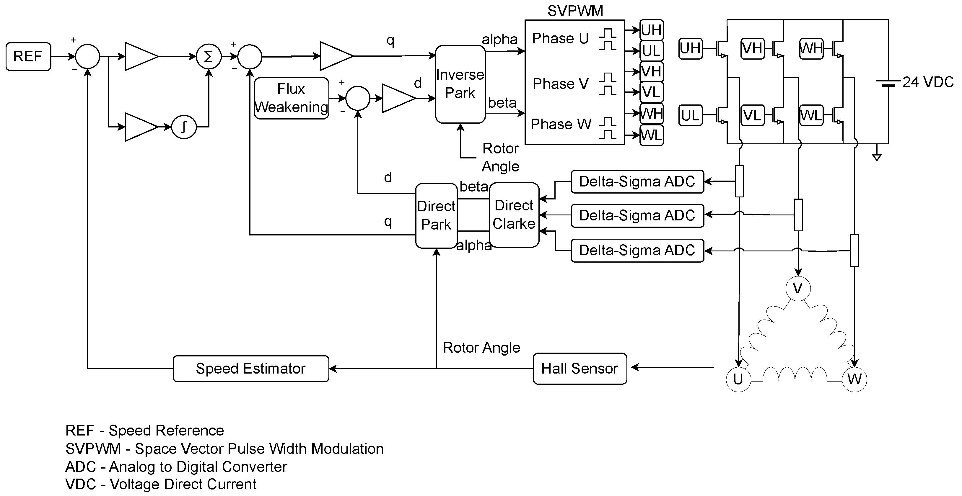
The proposed FOC method takes the direct FOC approach and uses only a Hall Sensor to obtain the rotor angle value, which is connected to an external Integrated Circuit (IC) used to compute the speed of the rotor. The rotor angle is used in the transforms that take place inside the FOC for determining direct and quadrature components used for the flux and torque controllers, respectively. The direct Clarke, direct Park, inverse Park, and space vector pulse width modulation techniques and transforms are used for torque and flux control. The inverse and direct Park transforms use the electrical angle of the rotor and consider the motor pole–pair number for correct computation, as shown in
Figure 1.
As shown in the figure, the PI controller components, error computation for their inputs, and reference values are referred to as the control element of the proposed system, meaning that the d and q components are referred to as the control signals. A PI structure is used for speed control, as described in Equation (1). A P structure is used for the torque and flux controllers, as shown in Equations (2) and (3) below.
In our case, both execution and output signals are fed back to the loop, taking into consideration that execution signals that are the phase currents of the motor help in computing the direct and quadrature components for the controllers alongside the angle in the case of flux and torque, while the speed signal assists the speed controller. In this case, the previously mentioned Hall sensor helps in determining the angle, and consequently the speed. Thus, the element including the Hall sensor and speed calculator is referred to as the transducer element, and its output signals are used for error computation inside the control element, thereby closing the loops.
It can be observed that the speed loop is cascaded with the two parallel loops for the flux and torque, since the output of the speed PI controller serves as the reference to the torque controller. This promotes efficiency, as the optimal required torque is produced for the required speed value. For the flux, a weakening value is used as a reference in order to consume as little energy as possible.
In order to properly test and simulate the proposed model, MATLAB/Simulink software was used alongside Simscape libraries. The first block to be considered is the BLDC, which is parameterized using the motor’s technical specifications in order to respect similarities between simulation and experimental results. The parameters provided by the datasheet can be found in
Table 1.
Other parameters needed for modeling the BLDC are computed by using the datasheet [
18] given ones as per Equations (4) and (5), and shown in
Table 2.
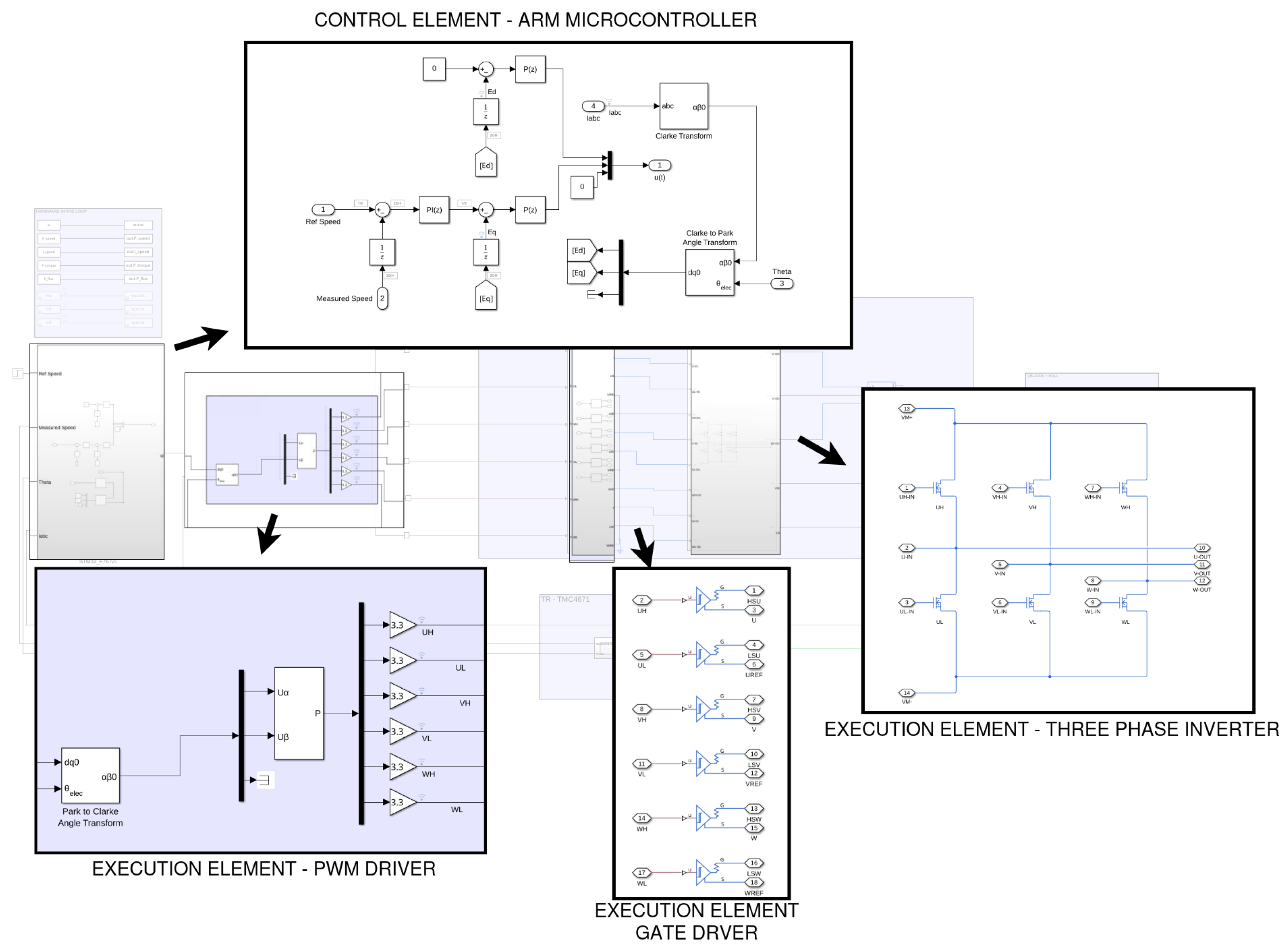
Figure 2 illustrates the complete control and execution architecture of the proposed embedded motor drive system implemented for real-time control of a three-phase inverter-fed electric machine. The diagram is organized into hierarchical blocks representing the flow of signals and operations across the system’s digital and power domains. Each functional block is modularly defined to reflect its role in the closed-loop control loop.
At the top of the figure, the control element is implemented on an ARM-based microcontroller, which executes the core algorithm responsible for speed and current regulation. This subsystem includes standard FOC transformations such as Clarke and Park transforms along with PI controllers for both the torque-producing current and the rotor speed. The processed control signals are converted into duty cycles and transmitted to the downstream execution chain as PWM references.
The PWM driver execution element receives these control signals and formats them into high-resolution pulse-width modulated signals. This module is critical in translating numerical control values into physical switching commands, operating with precise timing to maintain waveform integrity under high-frequency operation.
These PWM signals are passed to the gate driver block, which forms the interface between the low-power control logic and the high-power switching elements. The gate driver provides the electrical isolation and level shifting necessary for reliable operation of the inverter’s semiconductor devices. It ensures appropriate gate charge delivery to the power switches, enabling safe and efficient switching.
At the final stage, the three-phase inverter execution element receives the gate signals and synthesizes the desired AC output from a DC supply. The inverter employs a standard six-switch topology to generate three-phase voltage waveforms corresponding to the reference signals provided by the controller. This output drives the connected machine, closing the control loop.
The arrows denote the unidirectional flow of information and control, from algorithmic computation to physical actuation. The modular structure of the system enables scalable deployment across various hardware configurations and facilitates Model-in-the-Loop (MIL) testing for validation.
This architectural decomposition demonstrates a tightly integrated hardware-software system, balancing control fidelity with execution speed. It enables deterministic operation and supports the rigorous timing requirements of embedded motor control applications such as electric propulsion, robotics, and power conversion systems.
3. Hardware Approach and Implementation
The chosen hardware parts for the physical model implementation are as follows:
Controllers and direct transforms are implemented on an ARM based microcontroller.
A specific IC is used for the PWM engine (part of the execution element) as well as the Hall sensor interpreter and current ADCs (part of the transducer element).
For the gate driver and three-phase inverter used to drive the motor, another specific IC evaluation board is used (part of the execution element).
For the motor, we use a brushless DC motor (process) incorporating a Hall sensor.
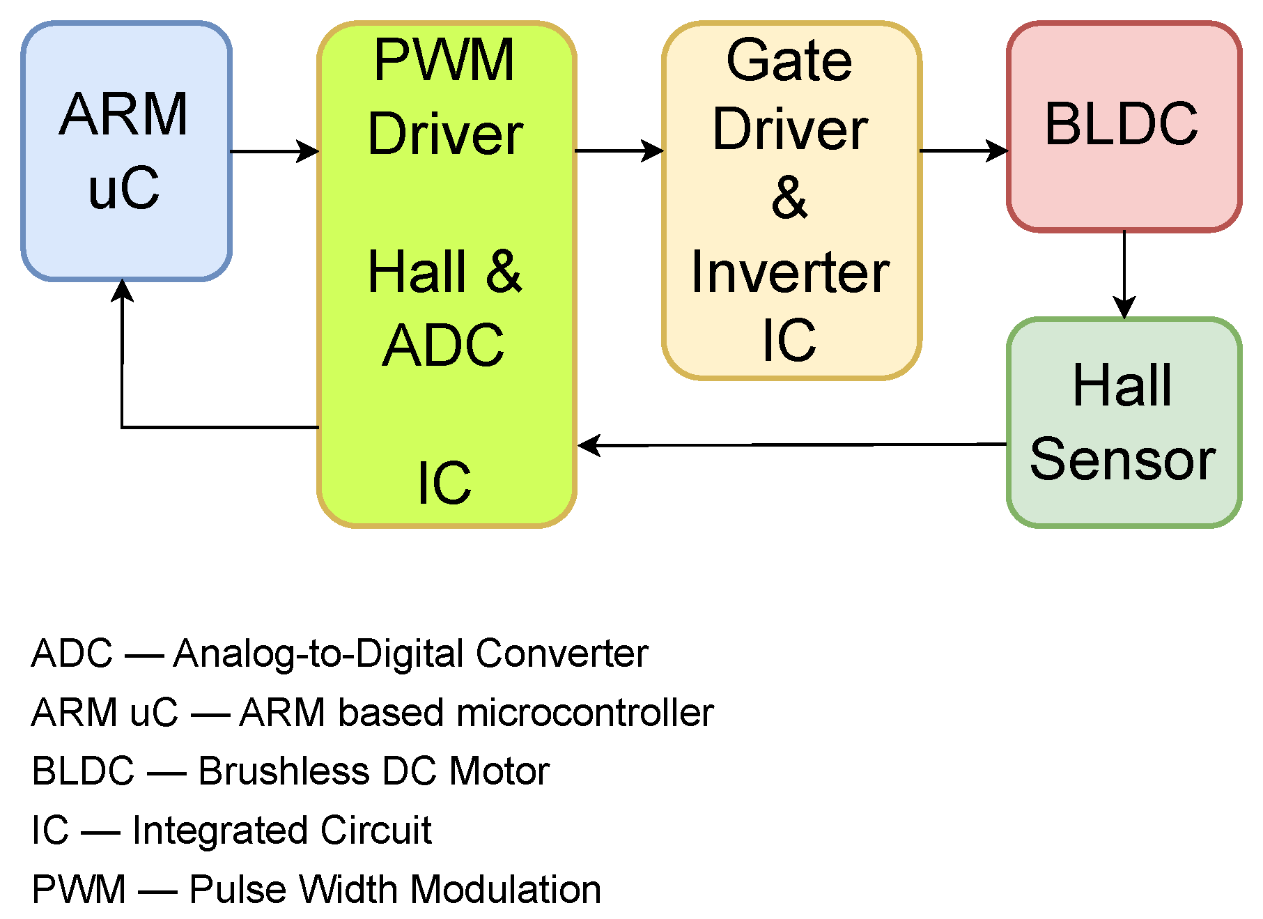
The hardware setup diagram, which implies the two previously-mentioned ICs along with the BLDC, ARM microcontroller, and Hall sensor, is shown in
Figure 3.
For enhanced system performance, the angle value needs to be obtained quickly enough to transmit the correct and inputs to the SVPWM, although the D and Q components do not change in that time. Therefore, a single IC is used for both the PWM engine, which is part of the execution element, and the transducer element. By using this IC instead of the microcontroller’s PWM channels, we ensure correct functionality of the motor regardless of the microcontroller’s performance in terms of computation speed. The Hall sensor signal interpreter which estimates the mechanical angle of the rotor is incorporated into the IC, and the value is multiplied by the number of pole pairs from the previously-configured internal register in order to compute the electrical angle of the rotor. This value is then transmitted directly to the inverse Park transform inside the IC, ensuring a smooth operation of the BLDC.
The loops involved are the torque and flux, both of which work in parallel, and the speed loop (the so-called outer loop), which is cascaded with the other two. The loop times are very important, having a major impact on both the dynamic and static performance characteristics of the system, such as response time and steady-state error, respectively.
4. Software Infrastructure
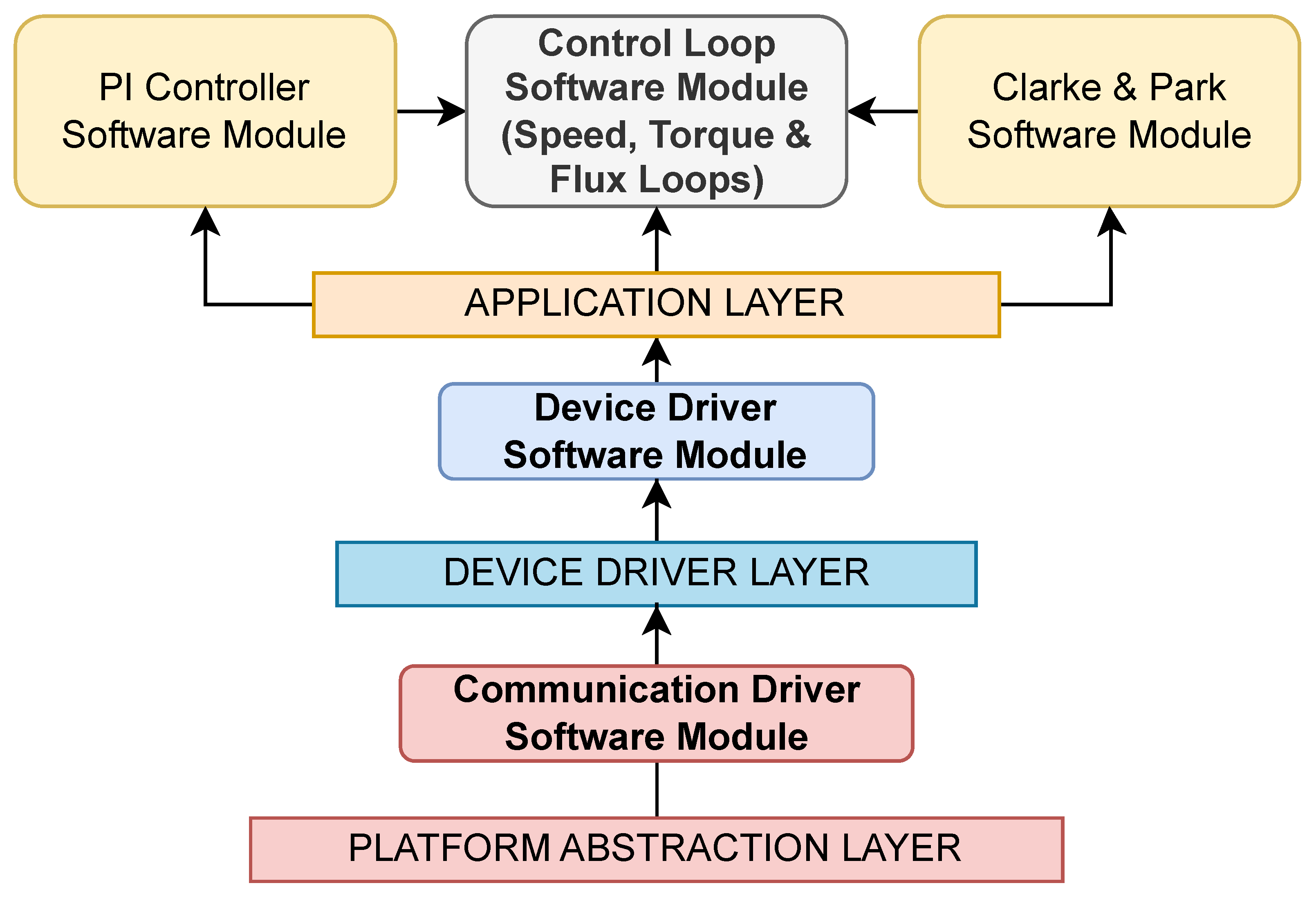
An ARM architecture-based microcontroller is used as the control element, and uses the software infrastructure shown in
Figure 4.
The foundation is the hardware layer, consisting of microcontroller soft cores and their on-chip peripherals (timers, General Purpose Input/Output (GPIO), Universal Asynchronous Receiver/Transmitter (UART), Direct Memory Access (DMA)) as well as external components such as ADCs, gate drivers, and position sensors. For motor control systems, this layer is responsible for acquiring phase current and rotor position measurements and for driving the inverter stage through PWM outputs.
Directly above this lies the vendor Software Development Kit (SDK)/Board Support Package (BSP) layer, which provides the first level of software interaction with the hardware. This includes startup code, board initialization, and Hardware Abstraction Libraries (HALs) for peripherals such as Serial Peripheral Interface (SPI), Inter-Integrated Circuit (I2C), UART, and timer modules.
To ensure cross-platform portability, the platform abstraction layer defines a uniform API that normalizes these vendor differences. Functions such as SPI writing-then-reading and GPIO value update setting act as canonical entry points, allowing higher layers to remain independent of the underlying processor family. For a motor control system, this abstraction enables the same communication protocol driver code for the two used ICs to operate seamlessly on different processing platforms.
The device driver layer encapsulates the logic required to interface the previously-integrated circuits and their functionalities, such as ADC configuration for current sensing, PWM generation, and gate-driver setup. These drivers implement register maps, initialization sequences, calibration procedures, and data acquisition routines, typically relying on SPI or I2C communication provided by the lower layers.
At the top is the application layer, where motor control algorithms are realized; this includes the implementation of FOC with its speed, torque, and flux regulation loops. The application layer integrates device drivers and platform services into a complete control solution while remaining agnostic to the underlying processing unit thanks to the layered design.
This structure not only promotes portability across heterogeneous platforms but also isolates time-critical motor control tasks from vendor-specific dependencies, enabling efficient reuse of algorithms and drivers across different hardware generations.
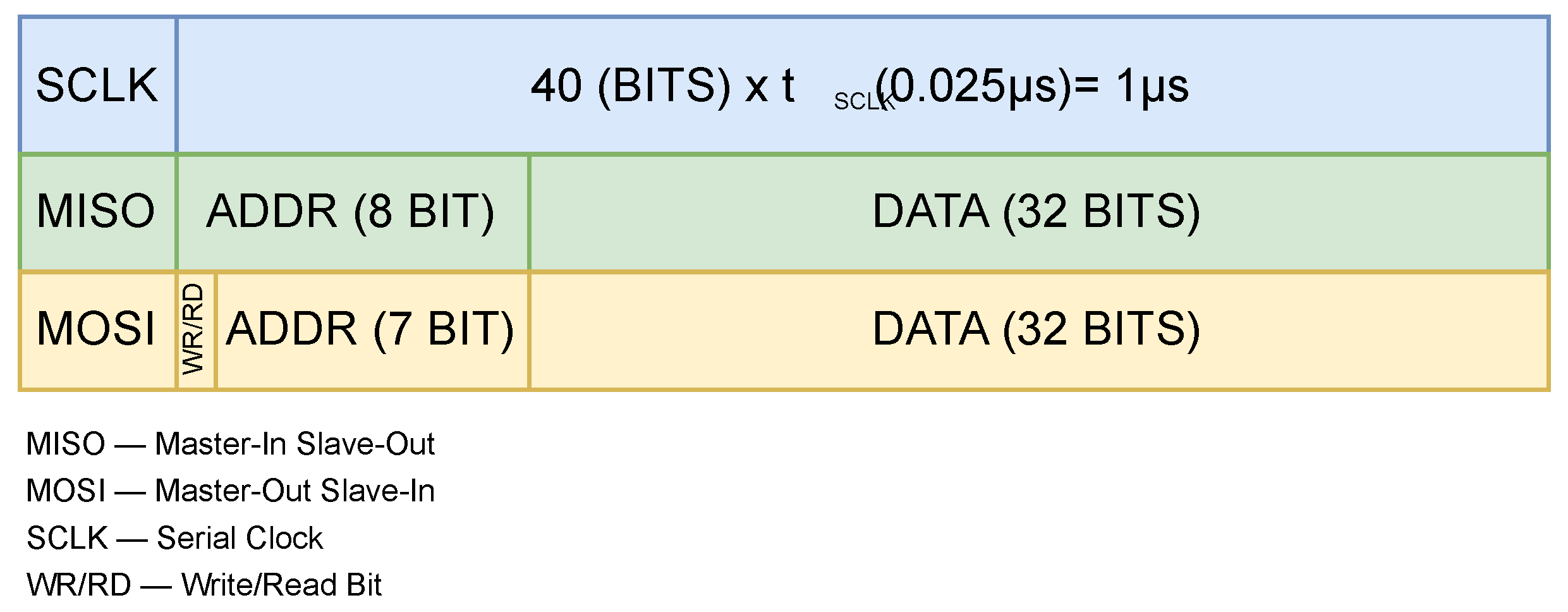
In this case, we used the IC’s maximum SPI frequency of 40 MHz, meaning that each bit of information alongside the communication lanes takes exactly 0.025 µs to transmit, as shown in
Figure 5.
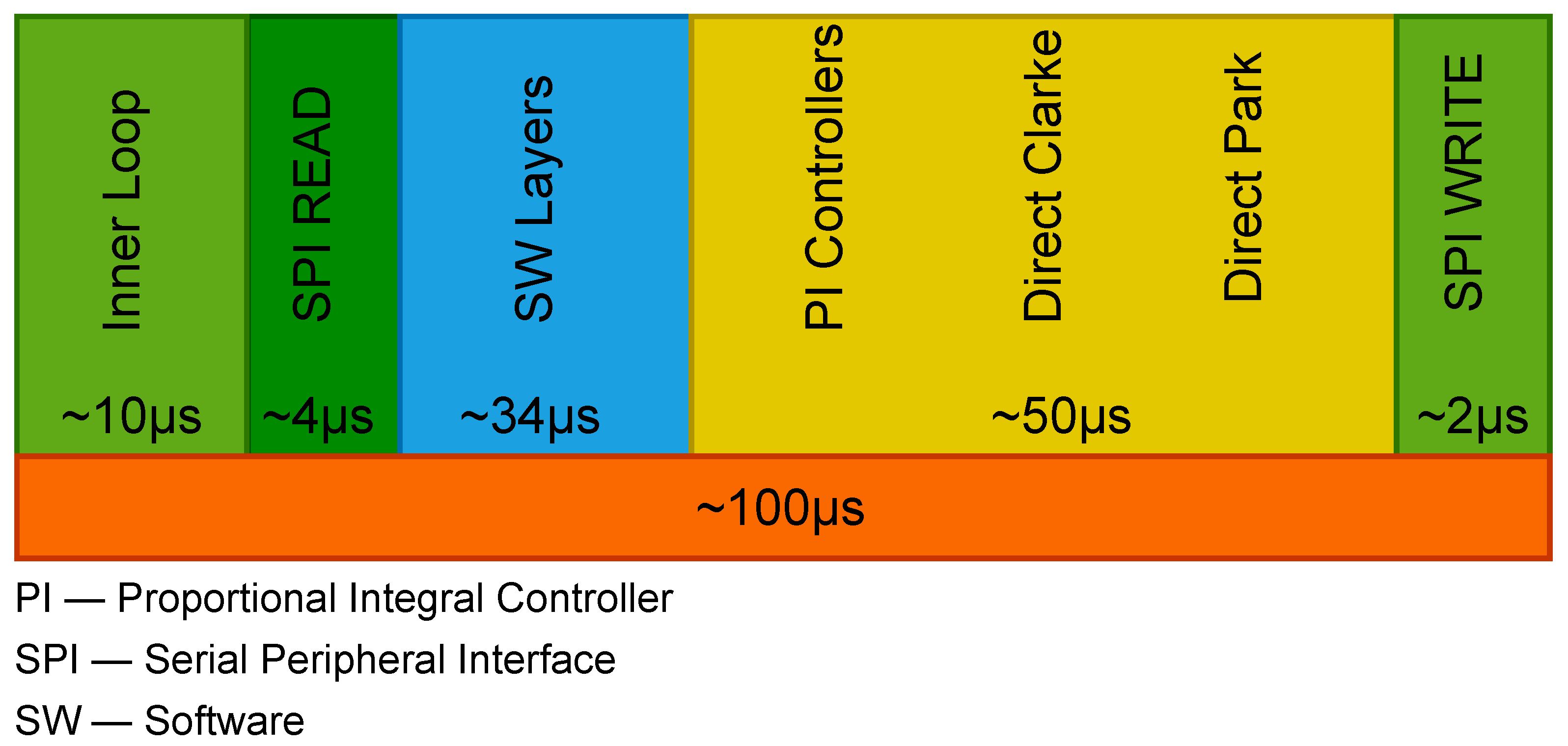
Taking into account that the register address is byte-sized and the register value is 32-bit sized, this means that the whole transfer consists of 40 bits; thus, a single SPI transfer requires precisely 1 µs. In our application, we perform a total of four readings: one each for the angle, speed, U and W currents, and V current. This results in a total SPI read time of 4 µs. For writing of the D and Q control signals to the execution element, we perform two writings, one for each of the D and Q components. In this way, we obtain a total SPI write time of 2 µs.
Considering that all three loops use controllers that are implemented inside a microcontroller with an ARM microprocessor, certain limitations appear when it comes to time and resources. These limitations are due to factors such as the SPI timing, software infrastructure’s implication of abstraction layers, and calculus of transforms such as the direct Park and direct Clarke transforms within the microcontroller. All of these factors result in a 100 µs loop time, as shown in
Figure 6.
The motor control software is organized into modules aligned with the layered architecture. The communication module forms part of the platform abstraction layer, standardizing access to peripheral interfaces such as SPI and UART while isolating higher-level modules from platform-specific details.
The device driver modules occupy the device driver layer, managing low-level interactions with the microcontroller’s peripherals that interact with the hardware components critical for FOC, including ADCs for phase current sensing, PWM modules for inverter control, and position sensors.
The control software modules form the application layer. They implement the main FOC control loop, including Proportional-Integral (PI) controllers for torque and speed regulation and Clarke and Park transforms for converting three-phase currents into the d–q reference frame. This modular separation ensures maintainability, facilitates reuse across different motor types, and allows the control logic to operate independently of the underlying hardware.
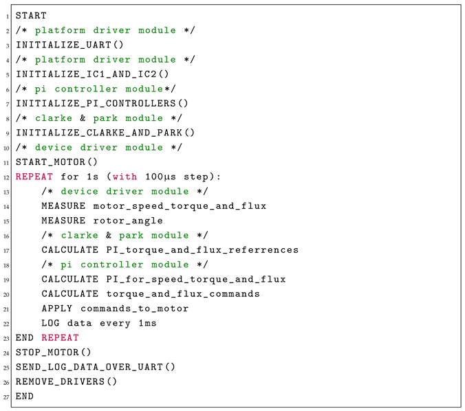
Figure 7 illustrates these modules and their interactions, highlighting the flow of data from device drivers through coordinate transformations and control algorithms to the PWM outputs driving the three-phase inverter.
The Main Control Loop (Listing 1) firmware module begins by initializing the communication interface (UART) and the two mentioned ICs (IC1—PWM generator and Hall interpreter; IC2—Gate Driver), with error handling to safely terminate and release resources if initialization fails. The motor controller is then configured, including PWM setup and closed-loop control preparation.
The PI controllers for speed, torque, and flux are initialized alongside the Clarke and Park transforms to implement Field-Oriented Control (FOC). At this point, a reference speed is defined and the motor is started.
The closed-loop control executes with a 100 µs time step over 1 s. At each iteration, the motor speed, torque, flux, and rotor angle are measured. The speed error is processed by a PI controller to compute the torque demand, while the torque and flux errors are regulated through corresponding PI controllers. The resulting voltage commands are applied to the motor, with data logged at every 1 ms.
After the test time, the motor is safely stopped, the logged data are transmitted via UART, and all drivers and resources are released to ensure safe system shutdown.
| Listing 1. Main control loop. |
![Applsci 15 11018 i001 Applsci 15 11018 i001]() |
5. Model-in-the-Loop and Interface Development
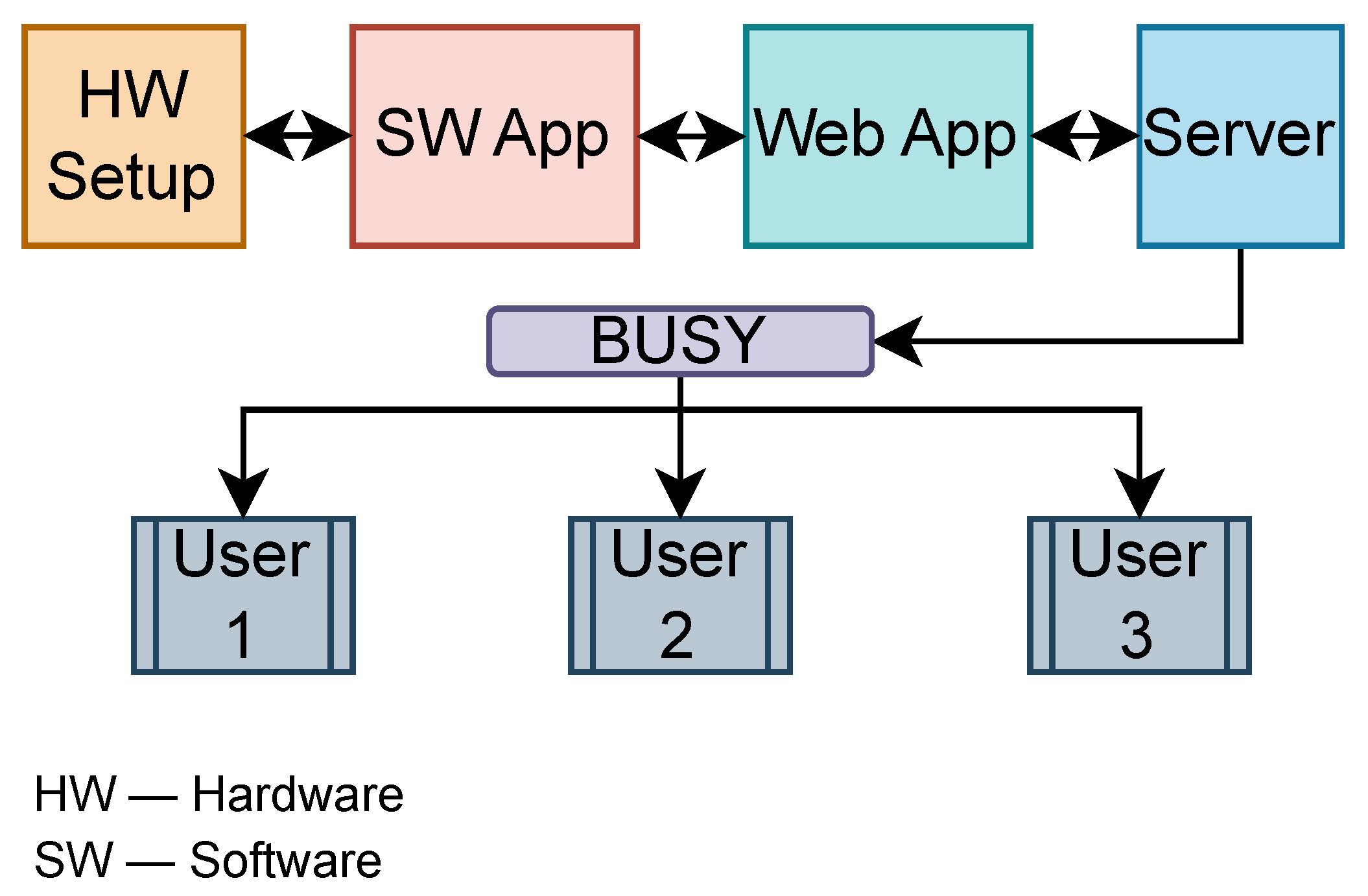
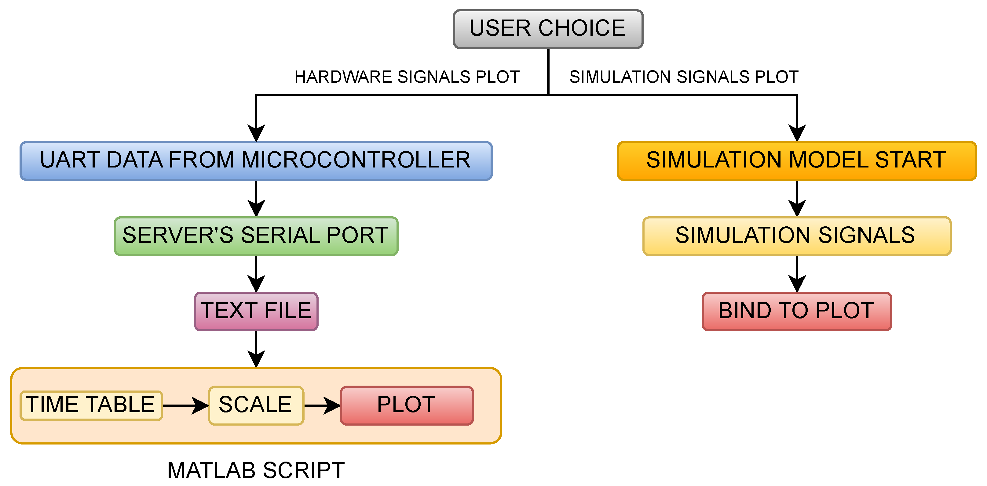
In most cases, an MIL implementation is used for a better comparison, and sometimes even to link between simulation and experimental results. Here, the proposed implementation is performed using Simulink’s support for developing a Web Application (Web App) which is to be linked with the previously mentioned software algorithm, which assures a better perspective on hardware and simulation data while providing a way of comparing the two sets of signals. The diagram of the proposed model for the whole application is shown in
Figure 8.
The framework is built with modularity and scalability in mind, allowing users to adapt it to different motor ratings, power levels, and converter switching frequencies. Motor-specific parameters such as rated speed and voltage along with current limits are configurable via backend scripts. A hardware abstraction layer further decouples the control logic from platform-specific dependencies, enabling portability across microcontroller platforms and converter topologies. This design supports flexible deployment in both educational and industrial contexts.
The way the Web App works is that inside the software algorithm after BLDC has run for about 1 s (measured by assuring a total of 10,000 loops, each taking 100 µs), 1000 values of the speed, flux, and torque signals are logged approximately 1 ms apart from each other. Therefore, 1000 points of each signal previously mentioned are transmitted over UART to a server (which is connected to the microcontroller) in order for it to process, log, and plot the data for a 1 s run time. By transmitting the index (ranging from 0 to 999), speed, torque, and flux decimal-coded values on the serial port, the Web App accesses the terminal that captures the transmitted UART signals. The values are then parsed into a text file that is later processed by the internal MATLAB script inside the Web App in order to plot the hardware signals.
The way the Web App’s user interface works is that the user is able to change the reference and PI controller values, after which the simulation and hardware models have to be run separately by pressing the corresponding button.
When the button of the corresponding hardware model is clicked, the script starts to build the program with user-specified data, uploads the binary file to the microcontroller, and runs the program. While the program runs, the MATLAB script waits for 10 s for the program to finish running; at the same time, the serial port is opened and waits for values to be captured.
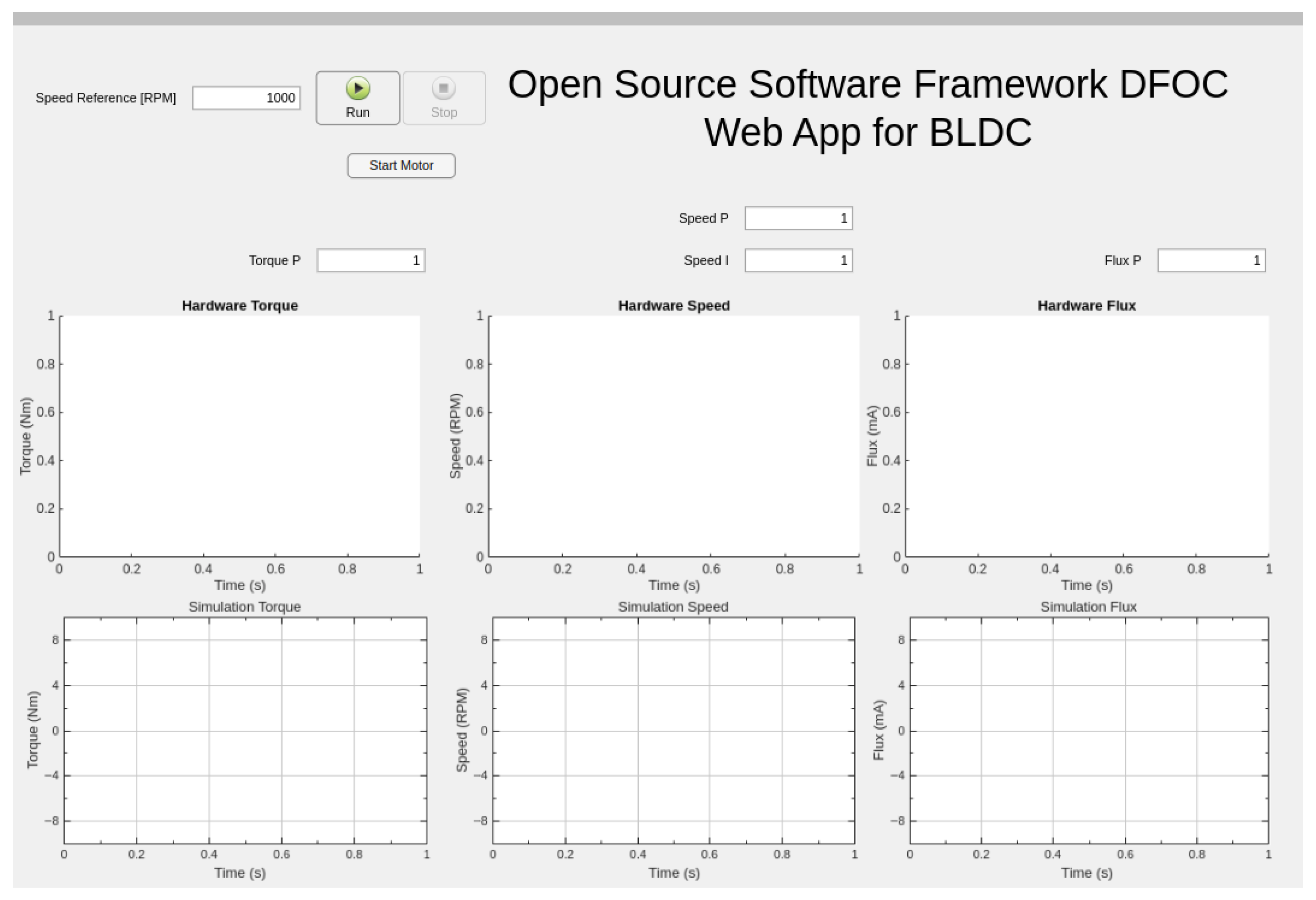
The data are then read back, processed, and organized into timetables, thereby plotting each signal of the hardware setup. The interface enables the user to set a reference speed in Revolutions Per Minute (RPM), adjust the proportional and integral gains for the speed, torque, and flux control loops, and control the motor operation through dedicated buttons, as shown in
Figure 9.
The top section of the GUI provides input fields for controller parameters and operational commands. The lower portion displays six real-time plots that visualize both hardware and simulation data. The first row presents hardware-acquired measurements of the torque, speed, and flux, while the second row displays the corresponding simulation results. Each plot maps amplitude versus time, enabling direct comparison between real-world behavior and simulated performance. This GUI environment supports interactive tuning and evaluation of control strategies, serving as a valuable tool for both development and experimental validation of FOC in BLDC motor applications.
The user can choose to start the physical model, which is handled by the MATLAB R2024b script that accesses the server’s terminal in order to modify, compile, and re-upload the source code, with the data expected to be transmitted on the serial port at the end and then processed and plotted. If the simulation model is chosen, the simulation starts with the set parameters using the integrated Simulink model.
In the end, the application can be deployed by using the MATLAB Web Server application, which allows for specific Web Apps to be deployed on a server and grants remote access to the application. Therefore multiple users can access the same model to view the data, although only one user at a time can start or stop the simulation/hardware runs. While MATLAB is a licensed platform, the system architecture is designed such that only a single host machine requires a MATLAB license. Users can access the GUI remotely via a web interface, allowing them to test and deploy control algorithms on shared hardware without requiring individual MATLAB installations. This approach balances the robustness of MATLAB-based development with the accessibility of web-based deployment, enabling collaborative experimentation and reducing overall licensing costs. The Web App’s internal structure is shown in
Figure 10.
6. Simulation and Experimental Results
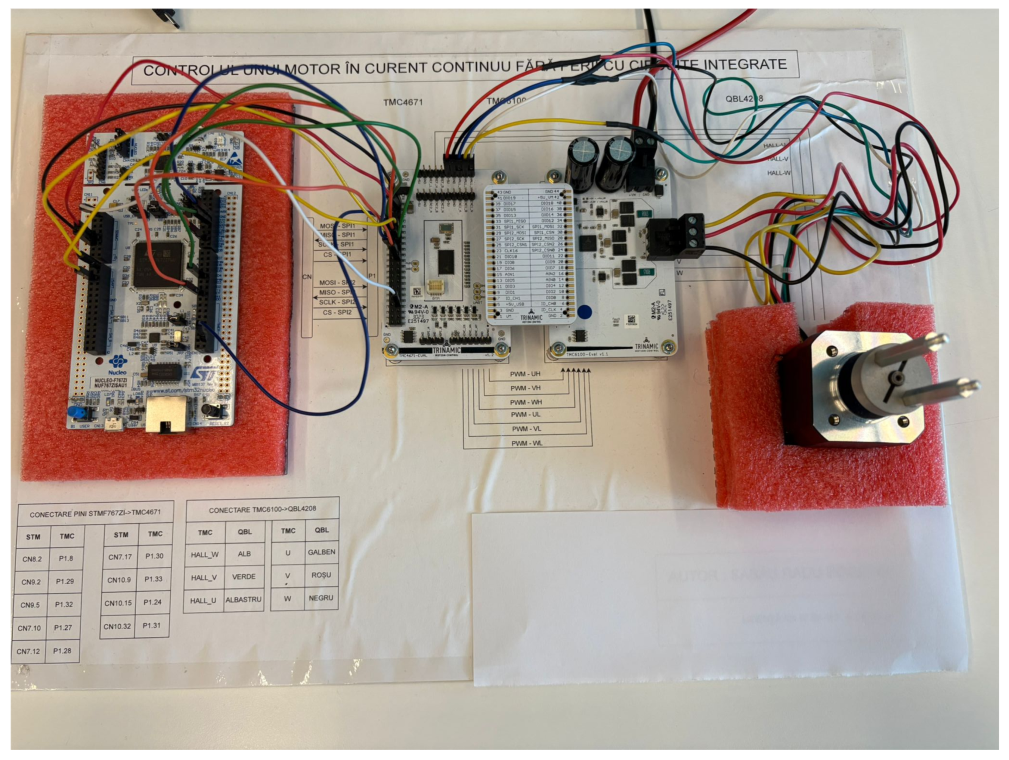
Figure 11 shows the physical model of the system used to test the whole application.
The parameters of the BLDC used for both simulation and experimental tests are described in
Table 1 and
Table 2. The other parameters of the system, such as discretization time of the controllers (only for the speed controllers, since the torque and flux ones are proportional only, meaning that the discretization time can be irrelevant in this case), switching frequency, and other timing properties of the execution element can be found in
Table 3.
To properly test the proposed system using a delta-wound BLDC motor, the proportional gains for torque (
) and flux (
) are assumed to be equal and derived as follows:
For the speed loop, a model-based tuning approach is employed using the motor’s rotor inertia and torque constant. The controller crossover frequencies are defined as follows:
The proportional and integral gains for the speed loop are calculated as follows:
The reference speed of 2000 RPM was selected based on practical and technical considerations relevant to typical BLDC motor applications. This speed lies within the common operating range of 1000–3000 RPM observed in devices such as fans, pumps, and small electric vehicles. Specifically, 2000 RPM serves as a representative midpoint, offering a realistic and steady-state operating condition that minimizes the influence of startup transients and high-speed nonlinearities. Moreover, it provides a balanced tradeoff between torque output and energy efficiency, making it a meaningful benchmark for evaluating the performance of the proposed control strategy.
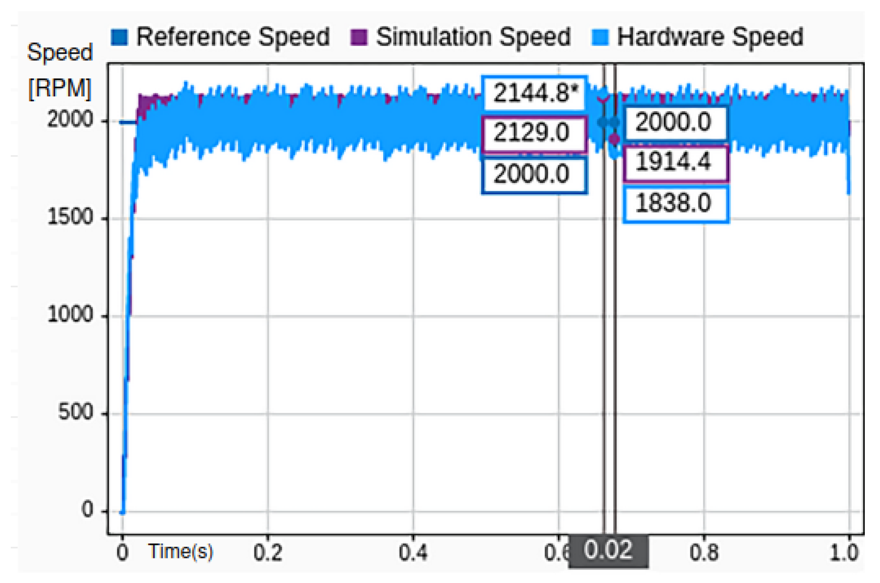
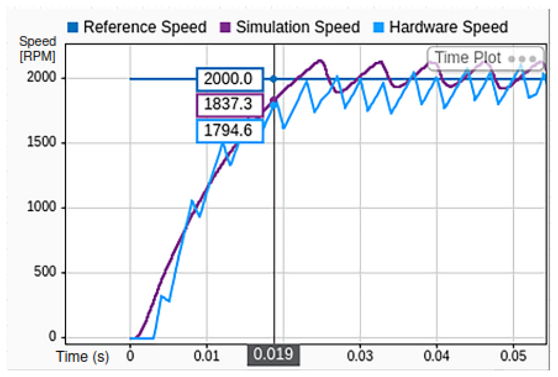
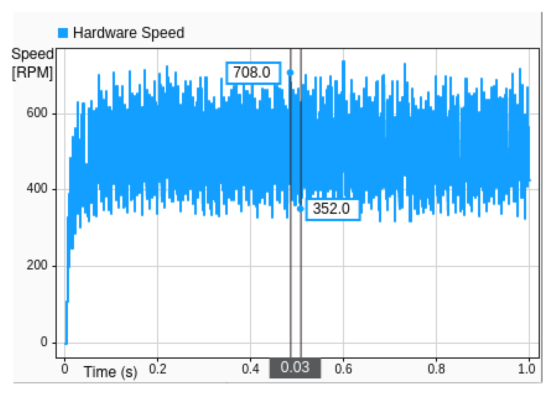
For a speed reference value of 2000 RPM, a comparative analysis between the simulated and experimentally measured motor speeds was conducted using MIL implementation. The results are illustrated in
Figure 12, which shows both the simulation output and hardware response under steady-state operating conditions.
The primary performance metric under consideration is the steady-state error variation, denoted as . This error represents the difference between the estimated motor speed and the desired reference value once transient effects have subsided. While small variations may persist due to hardware and sampling limitations, the outer PI controller eliminates the steady-state error in the control-theoretic sense. From the figure, it can be observed that the steady-state error for the hardware implementation is approximately 306 RPM, corresponding to 7.65% of the rated speed. In contrast, the simulation result exhibits a smaller error of 215 RPM, which equates to 5.37% of the rated speed.
This discrepancy highlights the inherent differences between the idealized simulation environment and the physical hardware, where factors such as inverter nonlinearities, sensor inaccuracies, and real-time processing delays contribute to increased deviations. Nevertheless, the close correlation between the two results validates the effectiveness of the proposed control strategy and underscores the utility of MIL as a robust testing methodology for control system development.
In terms of dynamic performance, the transient response of the system to a speed reference of 2000 RPM is analyzed by comparing both the simulated and experimental (hardware) speed signals. The comparison is presented in
Figure 13, where the rise time of each response is evaluated as an indicator of the system’s responsiveness to reference changes.
It can be observed that both the simulation and hardware implementations achieve a response time of approximately 19 milliseconds. However, the simulation exhibits a slightly faster rise, reaching the target speed marginally earlier than the hardware system. This small deviation is primarily attributed to the ideal conditions assumed in the simulation environment, which neglect real-world factors such as the sensor delay, inverter switching transients, and processor execution latency.
Despite this minor difference, the close agreement between the two responses confirms the fidelity of the simulation model and validates its effectiveness in predicting the dynamic behavior of the real system. The result also demonstrates the capability of the designed control structure to achieve fast and stable speed tracking under step input conditions in both simulation and practical implementation.
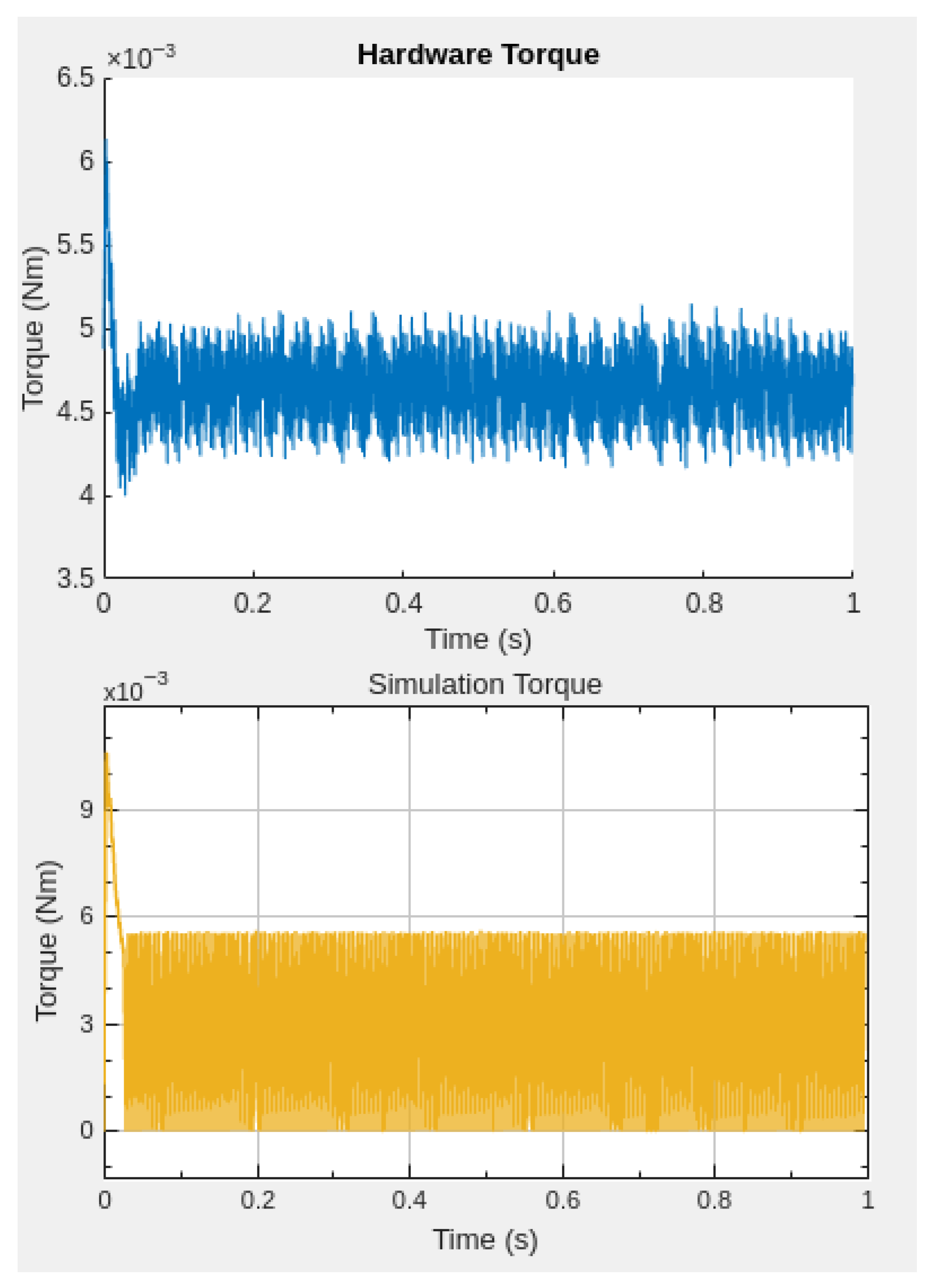
For the same speed reference value of 2000 RPM, the torque response is analyzed by comparing the simulated and experimental torque signals, as shown in
Figure 14.
Following a response time of approximately 19 milliseconds, consistent with the previously observed speed response, the torque current stabilizes at a steady-state value of approximately 120 mA. During the transient phase, the simulation exhibits a peak torque current of around 280 mA, while the hardware implementation registers a slightly lower peak of 250 mA. This discrepancy can be attributed to system non-idealities.
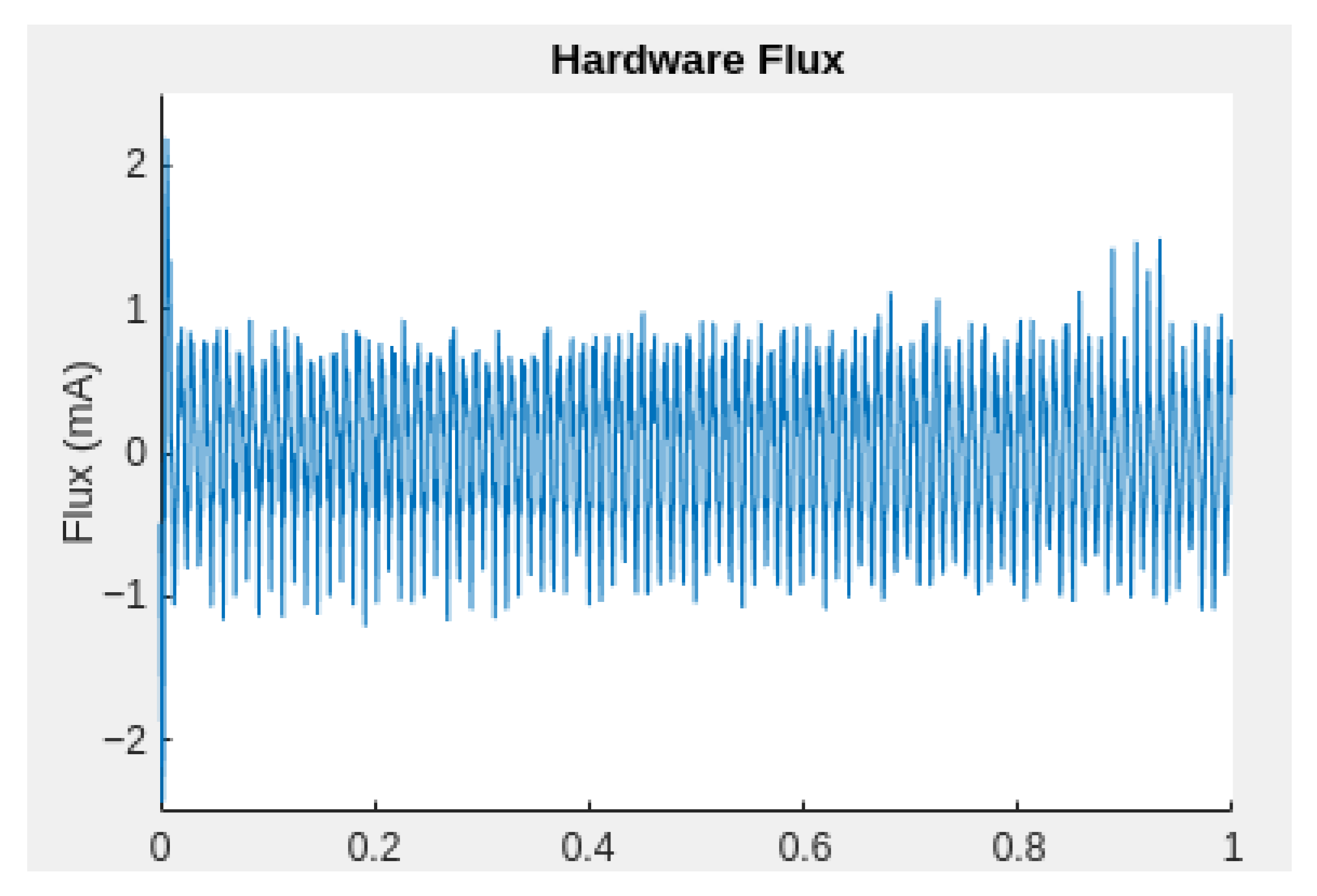
In contrast to the torque response, the stator flux is intentionally minimized during operation to achieve efficient and smooth control of the BLDC motor.
Figure 15 illustrates the hardware flux signal under the same operating condition, confirming that the flux is effectively maintained near zero, as intended.
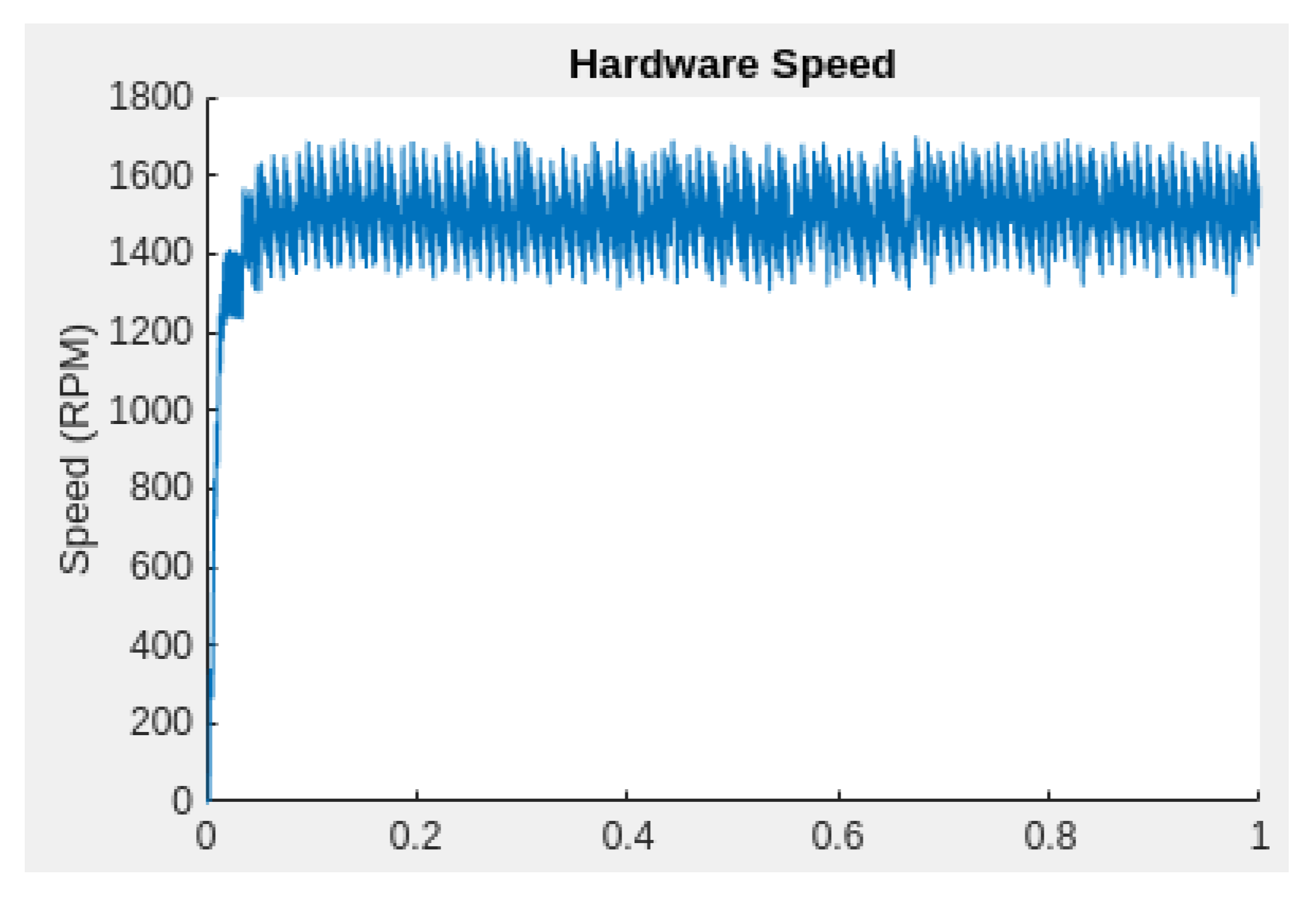
Figure 16 and
Figure 17 compare the simulation and hardware responses for a reduced speed reference of 1500 RPM, using the same PI controller parameters as in the 2000 RPM case. The test was conducted through the Web App interface to maintain consistent control settings across both platforms.
It can be observed that while both the simulation and hardware systems successfully stabilize around the reference speed, the steady-state error variation increases compared to the higher-speed case. Specifically, the fluctuation around the steady-state value reaches approximately 350 RPM, which corresponds to 8.75% of the rated speed. This suggests that the system exhibits greater sensitivity to load disturbances and internal dynamics at lower operating speeds when fixed controller gains are used.
The increased steady-state variation at 1500 RPM indicates that the controller’s ability to reject disturbances and maintain tight regulation diminishes as the operating point moves away from its nominal design target. This behavior highlights the importance of adaptive gain tuning or robust control strategies to ensure consistent performance across a broader speed range.
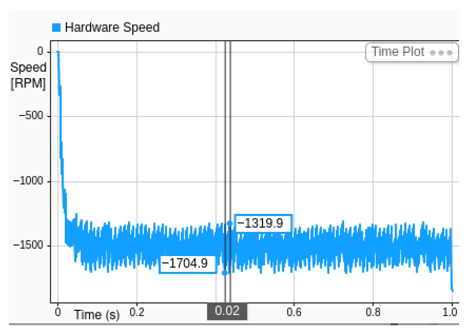
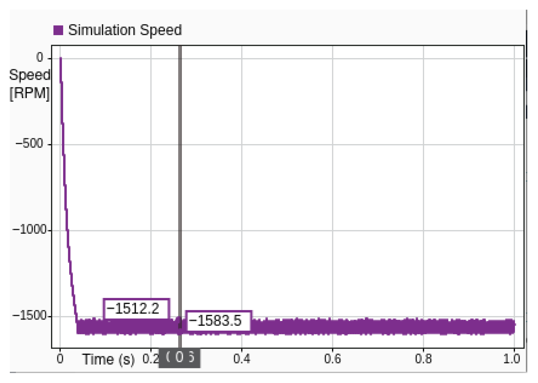
Figure 18 and
Figure 19 present a comparative analysis of simulation speed (purple) and hardware speed (light blue) for a system commanded to stabilize at −1500 RPM. This experiment specifically evaluates the controller’s performance in achieving reverse rotational motion and maintaining stability under negative speed regulation.
The simulation curve (purple) follows a slightly smoother and monotonic descent toward the target speed of −1500 RPM, representing a system with less noise and disturbance, resulting no observable overshoot and a lesser error.
The hardware response, represented in light blue, closely follows the simulation trend, but includes realistic dynamic effects. Initially, the system does not exhibit a slower rate of deceleration, but adds more oscillation to the system, likely due to motor inductance, measurement noise, or mechanical tolerances in the hardware. Despite these transients, the hardware speed ultimately revolves around the same final value of −1500 RPM, indicating successful regulation.
The close agreement in steady-state values between simulation and hardware validates the accuracy of the simulation model and the robustness of the implemented control strategy. The transient differences highlight the role of real-world effects that are not fully captured in simulation, such as delays, quantization, and external disturbances.
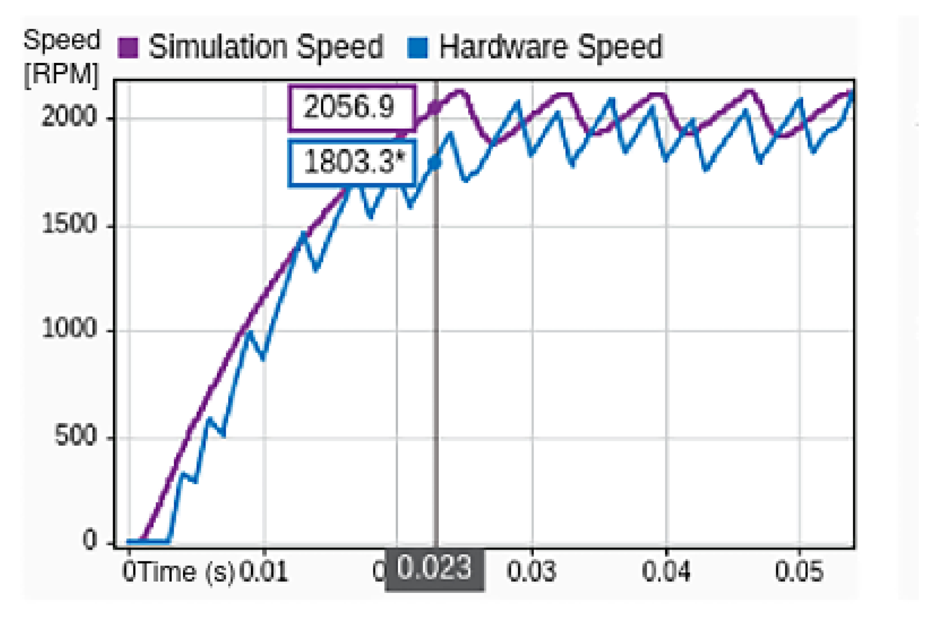
Figure 20 presents a comparative assessment between the simulation and MIL test results under conditions where a 100 g mass object was attached to the rotor in the hardware setup. This additional load introduces realistic inertia, enabling a more representative validation of system dynamics under physically constrained conditions.
The graph illustrates the simulation speed (in purple) and corresponding hardware speed (in blue) over a short time interval. The simulation trace follows a smooth trajectory, reflecting ideal system behavior in the absence of physical perturbations. It reaches a speed of 2056.9 RPMwithin approximately 0.025 s, demonstrating a rapid and uniform acceleration phase.
In contrast, the hardware trace exhibits noticeable oscillations superimposed on the general acceleration trend. The speed lags behind the simulation initially, reaching 1803.3 RPM at 0.023 s, evidencing the inertial delay introduced by the 100 g mass. This physical damping and oscillatory behavior are characteristic of an added moment of inertia in practical electromechanical systems, and are consistent with expectations based on system modeling.
Despite these dynamic deviations, the hardware response converges toward the simulation curve over time, particularly beyond the 0.04 s mark, where both traces stabilize near the same terminal speed. This convergence confirms that the control algorithm remains effective under load and is robust against disturbances introduced by mass-induced inertia.
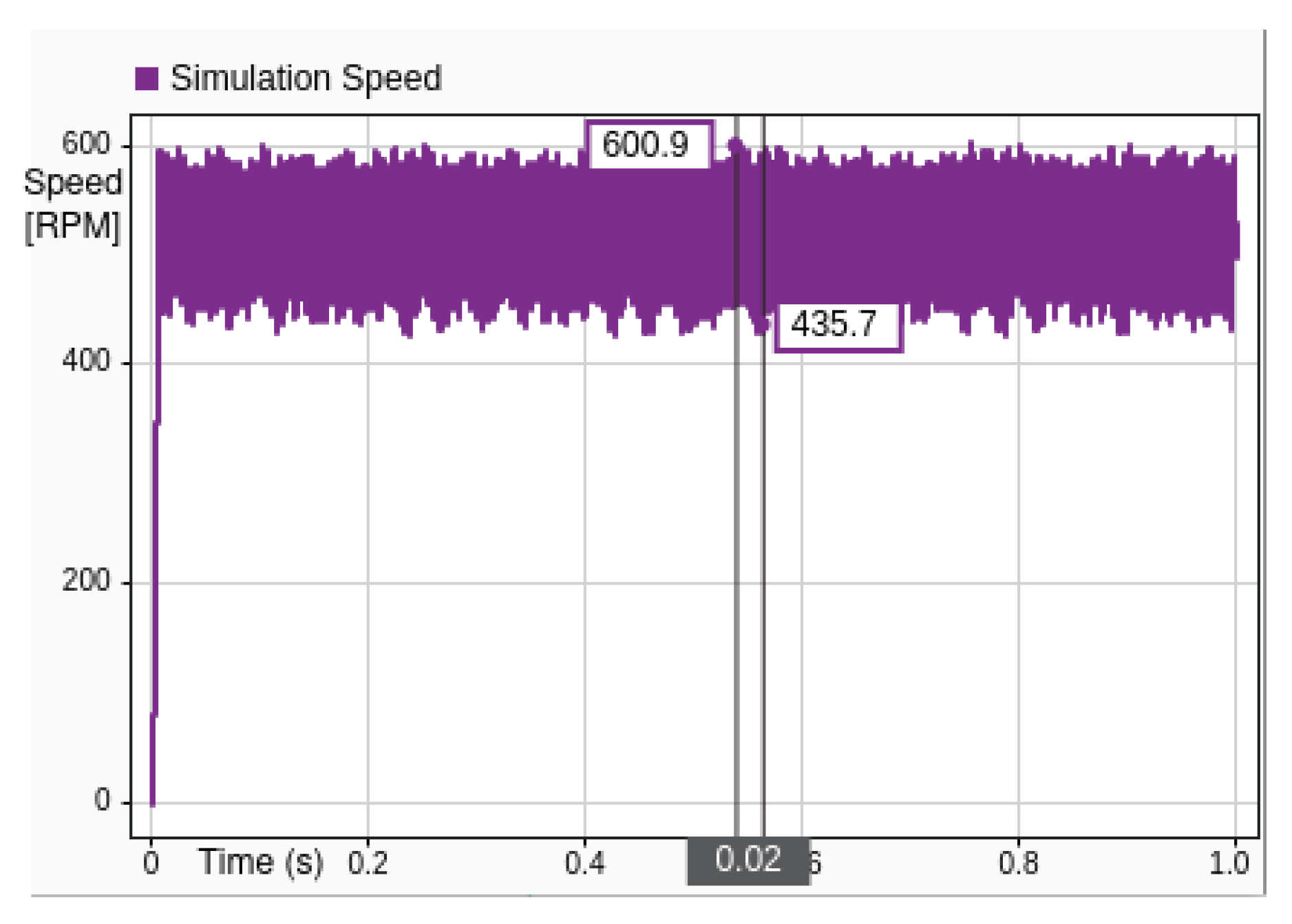
Figure 21 and
Figure 22 present a comparative analysis of system performance under simulation and MIL conditions, captured through time series plots of execution speeds.
Figure 21 illustrates the simulation speed, while
Figure 22 depicts the corresponding hardware speed during experimental deployment.
In the simulation environment, the system achieves a peak execution speed of approximately 600.9 RPM, with a minimum observed dip to around 435.7 RPM. The plot indicates generally stable behavior with speed values concentrated within the upper band, suggesting a high degree of consistency and minimal variance.
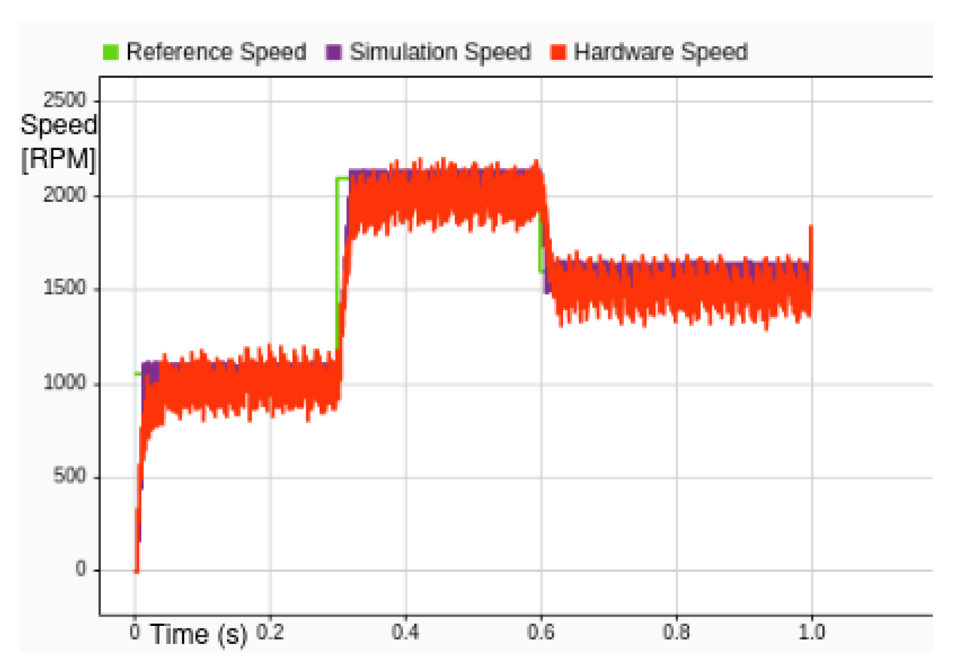
Figure 23 presents the transient response of the BLDC motor to a step change in reference speed, demonstrating the system’s ability to track dynamic inputs with minimal overshoot and acceptable settling time. This result validates the effectiveness of the proposed control strategy under non-steady-state conditions and highlights the framework’s capability for real-time adjustment and evaluation. The test confirms that the system maintains stability and responsiveness during speed transitions, supporting its suitability for dynamic motor control applications.
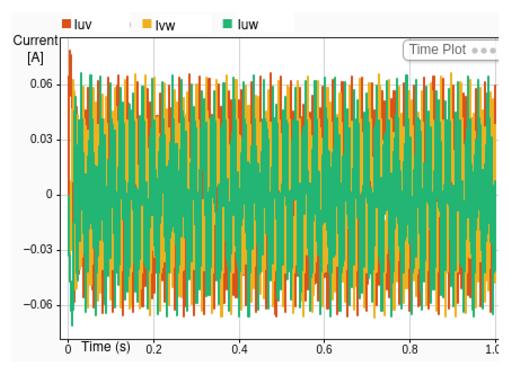
Figure 24 presents the simulated phase currents corresponding to the step-change in reference speed shown in
Figure 23.
7. Conclusions
This paper has presented a practical and cost-effective implementation of Direct Field-Oriented Control (DFOC) for Brushless DC (BLDC) motors using an open source software framework, resulting in an application that is independent of the used hardware. The novelty of this work lies in its integration of a lightweight control framework that operates effectively with a single Hall sensor. Unlike open-source platforms such as SimpleFOC, VESC, and ODrive, which often require dedicated hardware or tuning expertise, the proposed solution enables rapid prototyping and centralized validation within Simulink. This distinction enhances accessibility for academic researchers and industry practitioners alike, offering a scalable and hardware-agnostic approach to motor control development and experimentation. A single Hall sensor and integrated circuitry are used as hardware components alongside the motor and processing unit. By leveraging Space Vector Pulse Width Modulation (SVPWM), direct and indirect transformation techniques, and a minimal hardware configuration, the proposed approach achieves reliable commutation with minimal positional feedback. The system demonstrates an execution speed of 100 µs per control cycle, enabling real-time operation on resource-constrained embedded platforms.
The proposed system was thoroughly modeled in MATLAB/Simulink and validated through MIL testing, demonstrating good correlation between simulation and real-world results. To facilitate direct comparison, simulation and experimental results are concurrently plotted in
Figure 12,
Figure 13 and
Figure 20. Our experimental findings confirm that the steady-state error diminishes with increasing speed and that the system response remains robust under moderate mechanical load conditions. Moreover, successful bidirectional operation and low-flux behavior emphasize the effectiveness of the torque and flux control loops.
A web-based application was also developed to interface between the simulation and hardware in real time, providing an accessible platform for performance visualization and tuning. This reinforces the system’s educational and development utility.
While the proposed framework shows reliable steady-state performance and supports web-based algorithm testing, limitations such as lack of dynamic load variation, MATLAB dependency, and incomplete transient characterization remain to be addressed in future work.
In summary, the proposed software infrastructure and DFOC solution work together to reduce sensor count and system complexity while maintaining reliable control, providing an attractive option for embedded motor control applications where cost, simplicity, and efficiency are critical. Future work might explore further reduction of the steady-state error at low speeds and integration of adaptive or learning-based control strategies.
