Article

Generalized Frequency Division Multiplexing—Based Direct Mapping—Multiple-Input Multiple-Output Mobile Electroencephalography Communication Technique

Department of Electrical Engineering, National Taiwan Ocean University, Keelung 20224, Taiwan
*
Author to whom correspondence should be addressed.
Appl. Sci. 2025, 15(17), 9451; https://doi.org/10.3390/app15179451
Submission received: 5 August 2025 / Revised: 26 August 2025 / Accepted: 27 August 2025 / Published: 28 August 2025
(This article belongs to the Special Issue Communication Technology for Smart Mobility Systems)

Abstract

Featured Application

The GFDM-based DM MIMO MECT can be applied to mHealth, telemedicine, and IoMT systems with ultra-low power consumption, high transmission data rates, and low latency.

Abstract

Electroencephalography (EEG) communication technology with ultra-low power consumption, high transmission data rates, and low latency plays a significant role in mHealth, telemedicine, and Internet of Medical Things (IoMT). In this paper, generalized frequency division multiplexing (GFDM)-based direct mapping (DM) multi-input—multi-output (MIMO) mobile EEG communication technology (MECT) is proposed for implementation with the above-mentioned applications. The (2000, 1000) low-density parity-check (LDPC) code, four-quadrature amplitude modulation (4-QAM), a power assignment mechanism, and the 3rd Generation Partnership Project (3GPP) cluster delay line (CDL) channel model D were integrated into the proposed EEGCT. The transmission bit error rates (BERs), mean square errors (MSEs), and Pearson-correlation coefficients (PCCs) of the original and received EEG signals were evaluated. Simulation results show that, with a signal to noise ratio (SNR) of 14.51 dB, with a channel estimation error (CEE) of 5%, the BER, MSE, and PCC of the original and received EEG signals were 9.9777 × 10⁻⁸, 1.440 × 10⁻⁵ and 0.999999998, respectively, whereas, with an SNR of 15.0004 dB and a CEE of 10%, they were 9.9777 × 10⁻⁸, 1.4368 × 10⁻⁵, and 0.999999997622151, respectively. As the BER value, and PS saving are 9.9777 × 10⁻⁸, and 40%, respectively. With the CEE changes from 0% to 5%, and 5% to 10%, the N0 values of the proposed MECT decrease by approximately 0.0022 and 0.002, respectively. The MECT has excellent EEG signal transmission performance.

1. Introduction

To meet the specifications of smart healthcare and Industry 4.0 application scenarios, fifth-generation (5G) and sixth-generation (6G) mobile technology must achieve very high data rates (up to 1 Tb/s), ultrareliable and extremely low latency, massive and near-instantaneous connectivity, and seamless broadband space-air-ground-sea coverage [1]. The important intelligence, sensing, control, and computing/technical aspects are integrated into the high-speed and high-energy-efficiency 6G mobile communication system to achieve effective data storage, processing, and performance requirements, and enable task-oriented communication. Radio resources in the frequency and space domains were used for 6G and mmWave communication, and massive multi-input-multi-output (MIMO) was designed to increase the spectrum and the network throughput, respectively. The era of 6G cellular mobile communication may span from 2030 to 2040 [2]. The data transmission rate of 6G technology is roughly 1T bps, 1000 times faster than 5G networks, and would support global communication 6G technology focuse on efficient spectrum utilization, energy-efficient networks, smart connectivity, fast communication, and holographic connectivity, and its real-life application scenarios include smart medical services, multi-sensory extended reality, smart cities, military surveillance, healthcare, and wireless brain-computer interfaces (BCIs), etc.
Electroencephalography (EEG) signals can be applied to BCI solutions in the emerging area of neuromarketing [3]. Currently, 5G technology supports EEG-enabled Internet of Things (IoT) application scenarios. These Internet of Medical Things (IoMT) devices enable the remote measurement of patients’ EEG signals through real-time data transmission over the 5G network, thus significantly aiding health monitoring in medical response efforts. BCI-based EEG technologies represent a broad spectrum of applications, including devices such as smart mobile wheelchairs and exoskeletons, and can also be used in therapeutic domains. EEG signals are recorded from the human brain, and the recorded signals may be transmitted using wireless body-area networks [4] via 5G-IoMT-based technology for the remote diagnosis and treatment of patients [4]. A Turbo encoder with a puncturing mechanism was integrated into the 5G-IoMT-based system to minimize the BER of the EEG signal. The performance of the received EEG signals was evaluated in terms of mean square error (MSE) and root mean square error. Lin et al. [5] have demonstrated advanced 5G/beyond 5G/6G technologies, which were developed and efficiently utilized in medical cloud computing, mobile applications, and the IoMT for detecting, managing, and mitigating the spread of Coronavirus disease 2019 and designing smart healthcare infrastructures for future pandemics.
Ultra-low power consumption and diverse application requirements are design challenges for next-generation multiplex access technology [6]. Generalized frequency division multiplexing (GFDM), an innovative physical-layer waveform, can meet these requirements. GFDM has higher spectral efficiency and lower out-of-band (OOB) emissions compared to orthogonal frequency division multiplexing (OFDM). Each GFDM-based block includes a number of subcarriers and subsymbols. These subcarriers are filtered using a root-raised-cosine (RRC) filter that is circularly shifted in the time and frequency domains. Low-latency and high-speed transmission applications can be achieved. The subcarrier-based RRC filter can result in a non-orthogonal GFDM waveform, and both inter-symbol and inter-carrier interference might increase. Wang et al. [7] analyzed the bit and frame error rates of low-density parity-check (LDPC) code-based GFDM communication technologies over Rayleigh fading and additive white Gaussian noise (AWGN) channels. The proposed analysis method can be used to evaluate different designs of GFDM-based communication technologies in terms of bit and frame error rates (FERs), which can be substantially impacted by quantization error. GFDM is a block-based non-orthogonal multicarrier modulation technology proposed for 5G mobile communication systems [8]. A polar-coded GFDM transmission system was implemented using a combination of binary polar coding and GFDM modulation. Simulation results show that the proposed polar-coded GFDM transmission system has better block error ratio performance compared to turbo-coded GFDM systems. Ssimbwa et al. [9] proposed a short-packet GFDM-based physical layer, in accordance with IEEE 802.11 wireless local area network standards, to reduce latency in industrial wireless networks. The preamble size, total number of subcarriers, and cyclic prefix length of the overall packet structure were optimized. The packet error rates of factory automation, smart grids, intelligent transport systems, and process automation for industrial applications were 10 9 ,   10 6 ,   10 5 , and 10 4 , respectively, with latencies of 0.25 ms, 3 ms, 10 ms, and 50 ms, respectively.
Multi-mode MIMO-GFDM with index modulation (IM) has been proposed to meet IoMT application requirements, such as high throughput, high spectral efficiency (SE), ultra-low latency, and low transmission bit error rates (BERs), machine-type communication, and tactile Internet communication [10]. GFDM has strong advantages in terms of low OOB emission, high SE, and low latency. The new mobile communication application has ushered in new requirements for the next-generation physical layer. GFDM is a flexible, non-orthogonal multicarrier technology that adjusts resource blocks based on different communication service scenarios. MIMO-GFDM-IM can achieve high SE, energy efficiency, and robustness while mitigating multipath channel interference [11]. A MIMO-GFDM-IM detection strategy with two filtering phases was presented, and the detection performance and computational complexity were evaluated. IM is a transmission information approach that transmits information through on/off states of subcarriers and can increase SE and energy efficiency. The computational complexity of IM has been investigated. Tasadduq [12] proposed continuous phase modulation (CPM)-based GFDM, and evaluated its transmission BER performance over Gaussian and frequency-selective fading channels. The BER performance of CPM-GFDM is superior to that of conventional GFDM. Each GFDM data block is divided into subcarriers and sub-symbols, and an RRC filter is applied to the data block. Space-time coded (STC)-based GFDM was proposed to overcome deep fading, and a high diversity gain, and a low average symbol error rate (SER) could be achieved [13]. The deep fading channels included Rayleigh, Nakagami-q, and Nakagami-m fading channels. The closed-form expressions of the average SER performance for the μ-ary quadrature amplitude modulation (μ-QAM)-based STC-GFDM mobile communication scheme were derived.
Cho et al. [14] proposed new LDPC-coded orthogonal modulation schemes to achieve high data rate communications in navigation satellite technology. They integrated (4500, 3924) and (9000, 3924) LDPC codes into the proposed system. The proposed schemes, with an FER of 10 3 ,   have a better error performance, with a carrier-to-noise ratio of 1.4 dB. A modified outage probability metric was designed to evaluate protograph-based LDPC codes over an uncorrelated Rayleigh fading channel [15]. The trade-off between accuracy and computational complexity was demonstrated, and the FER threshold for optimized LDPC codes was 10 4 . LDPC codes are known to be among the best error-correction coding technologies over multipath fading channels [16]. An efficient LDPC encoder with efficient memory resource usage was developed to generate the code-parity-check matrix and store the results of auxiliary computations for IoT-type devices. The experimental results show that the proposed algorithm has a significant advantage in terms of memory usage and decoding timing, compared to an encoder using the direct parity-check matrix representation. Rate-compatible (RC)-based LDPC code technology can enhance the error-correction performance by changing the code rate [17]. A Block Tag-based encoder with a non-fixed code length, and novel time division multiplexing methods were developed to decrease the latency of fixed-length communications, and increase throughput by reducing resource utilization, respectively. The effect of the random puncturing and shortening of the RC-based LDPC codes was assessed to further increase spectrum efficiency [18]. The robust decoding performance of CPM-based aeronautical telemetry was demonstrated. A low-power LDPC code encoder/decoder has been implemented.
The performances of OTFS (orthogonal time frequency space) and OFDM waveforms were evaluated at 28 GHz mmWave, and a mobile speed of 250 kmph using the 3GPP (3rd Generation Partnership Project) CDL (cluster delay line)-A, B, C NLOS (non-line-of-sight) channel model, and CDL-D, E LOS (line-of-sight) channel model [19]. The OTFS waveform performs better in terms of spectral efficiency, with a lower peak-to-average power ratio and a higher Doppler scenario waveform, compared to OFDM. Two or three-dimensional residual deep neural network (ResNET) channel estimation approaches were proposed using the 3GPP CDL-C urban macrocell channel model [20]. Simulation results showed that the proposed ResNET uplink channel estimation method has up to 2 dB gain compared to minimum-mean-square-error channel estimation. Earle et al. [21] presented a methodology to increase the simulation fidelity of a mobile channel model. The channel features were extracted using machine learning models to adaptively change the channel model parameters. 3GPP CDL channel models are commonly used in MIMO link-level simulations, and they involve a wide variety of propagation environments and frequency ranges. The higher the simulation accuracy, the better the fidelity between simulated and actual performance can be achieved. The first 5G industrial IoT standard channel model was released by the 3GPP in 2019 [22], and channel characteristics of volume-dependence, dual mobility, and absolute time of arrival were described. The NLOS and LOS application scenarios were introduced. A low-power GFDM-based underwater acoustic image transmission system was proposed [23]. Underwater images were received with a BER of 10 4 , with high PSNR values and high resolution.
The remainder of this paper is organized as follows: Section 2 presents the proposed GFDM-based DM MIMO MECT transmitter and receiver architecture. Section 3 reports and analyzes the simulation results. Section 4 discusses the related EEG transmission technologies relevant to the proposed framework. Finally, Section 5 provides the conclusions of this study.

2. Methods

Figure 1 depicts the proposed 4 × 4 GFDM-based DM MIMO mobile EEG communication technology (MECT). The DM MIMO MECT includes the following technical features: EEG signals input a (2000, 1000) LDPC code encoder with a code rate of 1/2, a column weight of 3, and row weight of 6; a 4 × 4 DM-based MIMO communication scenario; 4-QAM; a PAM; a packet-by-packet transmission method; a double-window detection scheme (DWDS) [23]; and serial-to-parallel (S/P) and parallel-to-serial (P/S) strategies. In terms of technical efficacy, low power consumption, high data transmission rates, and low latency can be achieved.
The carrier-sense multiple-access strategy with collision avoidance packet access was utilized to achieve multiuser communication. The EEG signal bit stream of the nth user ( E S n ) is input into the (2000, 1000) LDPC encoder, and the LDPC encoded EEG signal bit stream of the nth user ( E S C n ) is output. The E S C n is input to the serial-to-parallel (S/P) mechanism, and the S/P LDPC encoded EEG signal bit stream of the lth transmission antenna for the nth user ( E S C P n , l ) is output. The E S C P n , l is input to the 4-QAM module, and the 4-QAM S/P LDPC encoded EEG signal symbol stream of the lth transmission antenna for the nth user ( E S C P M n , l ) is extracted as the output. The E S C P M n , l is input to the GFDM module, and the GFDM-based 4-QAM S/P LDPC encoded EEG signal symbol stream of the lth transmission antenna for the nth user ( E S C P M M n , l ) is extracted as the output. After adding a cyclic prefix (CP), the GFDM-based 4-QAM S/P LDPC encoded EEG signal symbol stream of the lth transmission antenna for the nth user with the CP ( E S C P M M P n , l ) is extracted as the output. The E S C P M M P n , l is input to the PAM module, and the GFDM-based 4-QAM S/P LDPC encoded EEG signal symbol stream of the lth transmission antenna for the nth user with the CP and PAM ( E S C P M M P P n , l ) is extracted as the transmission signal.
The GFDM modulation of the lth transmission antenna for the nth user is detailed below.
The E S C P M n , l dimension is A × 1 , and comprises B subcarriers with C subsymbols, which satisfies the equation A = B × C . The vector E S C P M n , l is given by
E S C P M n , l = ( E S C P M n , l , 0 T , , E S C P M n , l , C 1 T ) T
E S C P M n , l , 0 = ( E S C P M 0 , n , l , 0 T , , E S C P M B 1 , n , l , 0 T ) T
E S C P M n , l , C = ( E S C P M 0 , n , l , C T , , E S C P M B 1 , n , l , C T ) T
where E S C P M b , n , l , c is the 4-QAM LDPC EEG signal symbol stream, transmitted on the bth subcarrier and the cth subsymbol of the lth transmission antenna for the nth user. g n , l , b , c [ e ] is the time and frequency transformations of the prototype filter of the lth transmission antenna for the nth user g n , l [ e ] , where e denotes the sampling index.
g n , l , b , c [ e ] = g n , l [ ( e c B ) m o d A ] e j 2 π b B e
The transmitted data from the lth transmission antenna for the nth user is expressed as follows:
E S C P M M n , l = ( E S C P M G n , l e ) T
E S C P M G n , l e = b = 0 B 1 c = 0 C 1 g n , l , b , c e E S C P M b , n , l , c
e = 0 , 1 , A 1
Let
g t n , l , b , c = ( g n , l , b , c e ) T E S C P M M n , l
where the dimension of F n , l is B C × B C and can be described as
  F n , l = ( g t n , l , 0,0 , , g t n , l , B 1,0 , g t n , l , 0,1 , g t n , l , B 1 , C 1 )
where g t n , l , k , m is the time and frequency-shifted version of g t n , l , 0,0 of the lth transmission antenna for the nth user. The relation between E S C P M M P n , l   and   E S C P M M P P n , l is expressed as
E S C P M M P P n , l = μ n , l E S C P M M P n , l
where μ n , l is the transmission power weighting factor of the lth transmission antenna for the nth user, and μ n , l { 30 30 , 29 30 , , 15 30 } .
The EEG signal received by the pth antenna, for the nth user, is given by
E S C P M M P P R n , p = l = 1 4 E S C P M M P P n , l h n , l , p + w n , l , p
where h n , l , p is the 3GPP CDL channel impulse response of the lth transmission antenna and the pth receiver antenna, for the nth user. l is 1, 2, 3, or 4, and p is 1, 2, 3, or 4. The S N R n , p , E E G , the signal-to-noise ratio of EEG packets received by the pth receiver antenna for the nth user, can be detected utilizing DWDS, denoted by the symbol ‘ S N R n , E E G ’. The process for the proposed EEG-based PAM for the GFDM-based 4 × 4 DM MIMO mobile EEG communication technology is summarized as follows:
  • Step 1: Use 4-QAM, and the (2000, 1000) LDPC code encoder to meet the quality-of-service requirements for mobile EEG transmission.
  • Step 2: Set the initial transmission power weighting of μ n , l   t o   23 30 for EEG signals.
  • Step 3: Measure the received S N R n , p , E E G .
  • Step 4: If the measured S N R n , p , E E G exceeds the mobile EEG transmission threshold at the required EEG BER of 10 7 , then update μ n , l to μ n , l = μ n , l , where is equal to 1/30.
    • If μ n , l 15 / 30 , go to Step 3; otherwise, go to Step 5.
  • Step 5: If the measured S N R n , p , E E G is less than the mobile EEG transmission threshold at the required EEG BER of 10 7 , then update μ n , l to μ n , l = μ n , l + , where is equal to 1/30.
    • If μ n , l < 30 / 30 , go to Step 3; otherwise, go to Step 4.
The receiver block diagram has the inverse function of the transmitter block diagram. The CP is removed. The received EEG packets are demodulated using a GFDM/4-QAM-based 4 × 4 DM MIMO demodulator, and the GFDM/4-QAM-based 4 × 4 DM MIMO demodulated EEG packets are extracted as output. The GFDM/4-QAM-based 4 × 4 DM MIMO demodulated EEG packets are input to the LDPC decoder, and the LDPC decoded EEG signals are extracted as output.

3. Results

The MATLAB 2024b-based 3GPP CDL channel model D [24] was integrated into the simulation. The 3GPP CDL channel model D is a LOS model, having a carrier central frequency of 28 GHz, and 400 km/hour mobile speed. The simulation parameters of the proposed 4 × 4 GFDM-based DM MIMO MECT are listed in Table 1.
Figure 2 shows the BER performance of the 4 × 4 GFDM-based DM MIMO MECT for the nth user. The ‘blue’, ‘green’, and ‘red’ lines denote perfect channel estimation (PCE), a channel estimation error (CEE) of 5%, and a CEE of 10%, respectively. When using 4-QAM transmission, the SNR values of the proposed MECT with the CEEs of 0% (PCE), 5%, and 10%, with a BER of 9.98 × 10 8 , are 14.1 dB, 14.5 dB, and 15.00 dB, respectively. The PCE has SNR gains of 0.4 dB and 0.9 dB, respectively, compared to CEEs of 5% and 10%.
Figure 3 shows the MSE performance of the 4 × 4 GFDM-based DM MIMO MECT for the nth user. The MSE is the evaluation parameter utilized for the received EEG signal.
The MSE of the original and received EEG signals using the 4 × 4 GFDM-based DM MIMO MECT is expressed as follows:
M S E = 1 W i = 1 W X i Y i 2
where X i , and Y i are the original and received EEG signals in the MECT, respectively, and W is the length of the EEG signal. The MSEs for CEEs of 0% (PCE), 5%, and 10% with a BER of 9.98 × 10 8 , are 1.44 × 10 5 , 1.44 × 10 5 , a n d   1.44 × 10 5 , respectively.
The BER performances are less than the MSE performances for CEEs of 0%, 5%, and 10%, and as the BER value decreases, the MSE value decreases.
Figure 4 shows the Pearson correlation coefficient (PCC) performance of the 4 × 4 GFDM-based DM MIMO MECT for the nth user. The PCC is expressed as follows:
r = X Y X Y W ( X 2 ( X ) 2 W ) ( Y 2 ( Y ) 2 W )
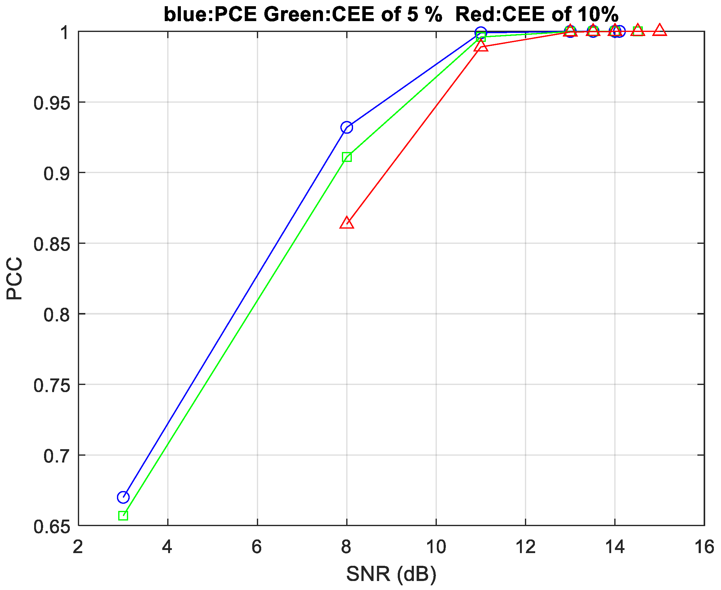
where X , and Y are the original and received EEG signals in the MECT, respectively, and W is the length of the EEG signal. If the PCC between signals X and Y is 1, then signals X and Y are identical; they are completely correlated. PCC values of 0–0.2, 0.2–04, 0.4–0.6, 0.6–0.8, and 0.8–1.0 correspond to ultra-low, low, medium, high, and ultra-high correlations, respectively, between signals X and Y. The SNR values of the proposed MECT with CEEs of 0%, 5%, and 10% with a PCC of 0.999999998 are 14.10 dB, 14.51 dB, and 15.00 dB, respectively.
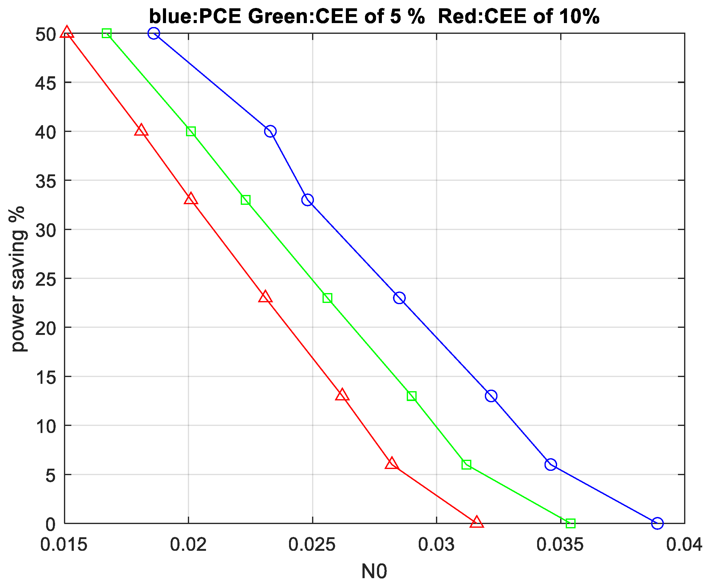
Figure 5 shows the power saving (PS) performance of the 4 × 4 GFDM-based DM MIMO MECT for the nth user. The PS is expressed as follows:
P S = 1 μ n , l × 100 % N 0 = 2 σ n , l , p 2
w h e r e   σ n , l , p 2 is the variance of the additive white Gaussian noise of the l-th transmission antenna, and the p-th receiver antenna for the nth user.
The N 0 values of the proposed MECT with CEEs of 0%, 5%, and 10% with 40% PS are 0.0223, 0.0201, and 0.0181, respectively, the BER value is 9.9777 × 10 8 . As the CEE changes from 0% to 5%, and 5% to 10%, the N 0 values of the proposed MECT decrease by approximately 0.0022 and 0.002, respectively.

4. Discussion

Table 2 lists the SNR, BER, MSE, and PCC values of the proposed MECT with CEEs of 0%, 5%, and 10%. The BER values of the proposed MECT with CEEs of 0%, 5%, and 10% with an 11.00 dB SNR are 8.68 × 10 5 ,   2.60 × 10 4 , and 6.42 × 10 4 , respectively. As the CEE increases from 0% to 5%, and from 5% to 10%, the BER increases by approximately 1.732 × 10 4 ,   and   3.82 × 10 4 , respectively. The BER values of the proposed MECT with CEEs of 0%, 5%, and 10% with a 13.51 dB SNR are 1.20 × 10 6 ,   3.99 × 10 6 , and 1.05 × 10 5 , respectively. As the CEE increases from 0% to 5%, and from 5% to 10%, the BER increases by approximately 2.79 × 10 6 ,   a n d   6.51 × 10 6 , respectively. The BER increase is smaller when the CEE increases from 0% to 5% compared to the increase from 5% to 10%. The SNR values of the proposed MECT with CEEs of 0%, 5%, and 10% with a   9.98 × 10 8 BER are 14,010 dB, 14.51 dB, and 15.00 dB, respectively. As the CEE increases from 0% to 5%, and from 5% to 10%, the SNR increases by approximately 0.41 dB, and 0.49 dB, respectively.
The MSE values of the proposed MECT with CEEs of 0%, 5%, and 10% with an 11.00 dB SNR are 3.36 ,   24.25 , and 68.04 , respectively. As the CEE increases from 0% to 5%, and from 5% to 10%, the MSE increases by approximately 20.89 , a n d   42.79 , respectively. The MSE values of the proposed MECT with CEEs of 0%, 5%, and 10% with a 13.50 dB SNR are 6.51 × 10 2 ,   3.91 × 10 1 , and 1.15 , respectively.
As the CEE increases from 0% to 5%, and from 5% to 10%, the MSE increases by approximately 3.259 × 10 1 , a n d   0.759 , respectively. The increase in MSE is smaller when the CEE increases from 0% to 5% compared to the increase from 5% to 10%. The SNR values of the proposed MECT with CEEs of 0%, 5%, and 10% with a   1.44 × 10 5 MSE are 14,010 dB, 14.51 dB, and 15.00 dB, respectively.
The PCC values of the proposed MECT with CEEs of 0%, 5%, and 10% with an 11.00 dB SNR are 0.99944 , 0.99600, and 0.98898, respectively. As the CEE increases from 0% to 5%, and from 5% to 10%, the PCC decreases by approximately 0.00344 , a n d   0.00702 , respectively. The PCC values of the proposed MECT with CEEs of 0%, 5%, and 10% with a 13.51 dB SNR are 0.999989228 , 0.999935264, and 0.999810395, respectively. As the CEE increases from 0% to 5%, and from 5% to 10%, the PCC decreases by approximately 0.000053964 , a n d   0.000124869 , respectively.
The decrease in PCC is smaller when the CEE increases from 0% to 5% compared to the increase from 5% to 10%. The PCC values for CEEs of 0%, 5%, and 10% with a   9.98 × 10 8 BER are 0.999999997622183 , 0.999999998, and 0.999999997622151, respectively. Thus, the received EEG signal is very similar to the original EEG signals.
The time length and sample frequency of the simulated EEG signal are 6959.97 s, and 160 Hz, respectively. The BER, MSE, and PCC values of the proposed MECT with a CEE of 10% and a 14.51 dB SNR are 8.9799 × 10 7 ,   6.46 × 10 2 , and 0.99999 , respectively. The received EEG signal shows nine amplitude errors. Figure 6 illustrates the original EEG signal in the time interval from 5803.2125 s to 5806.2125 s. Figure 7 shows the received EEG signal with a CEE of 10% and an SNR of 14.51 dB in the time interval from 5803.2125 s to 5806.2125 s. One of the amplitude errors is at 5804.71 s, where the original and received EEG amplitudes are 11 mV and 27 mV, respectively.
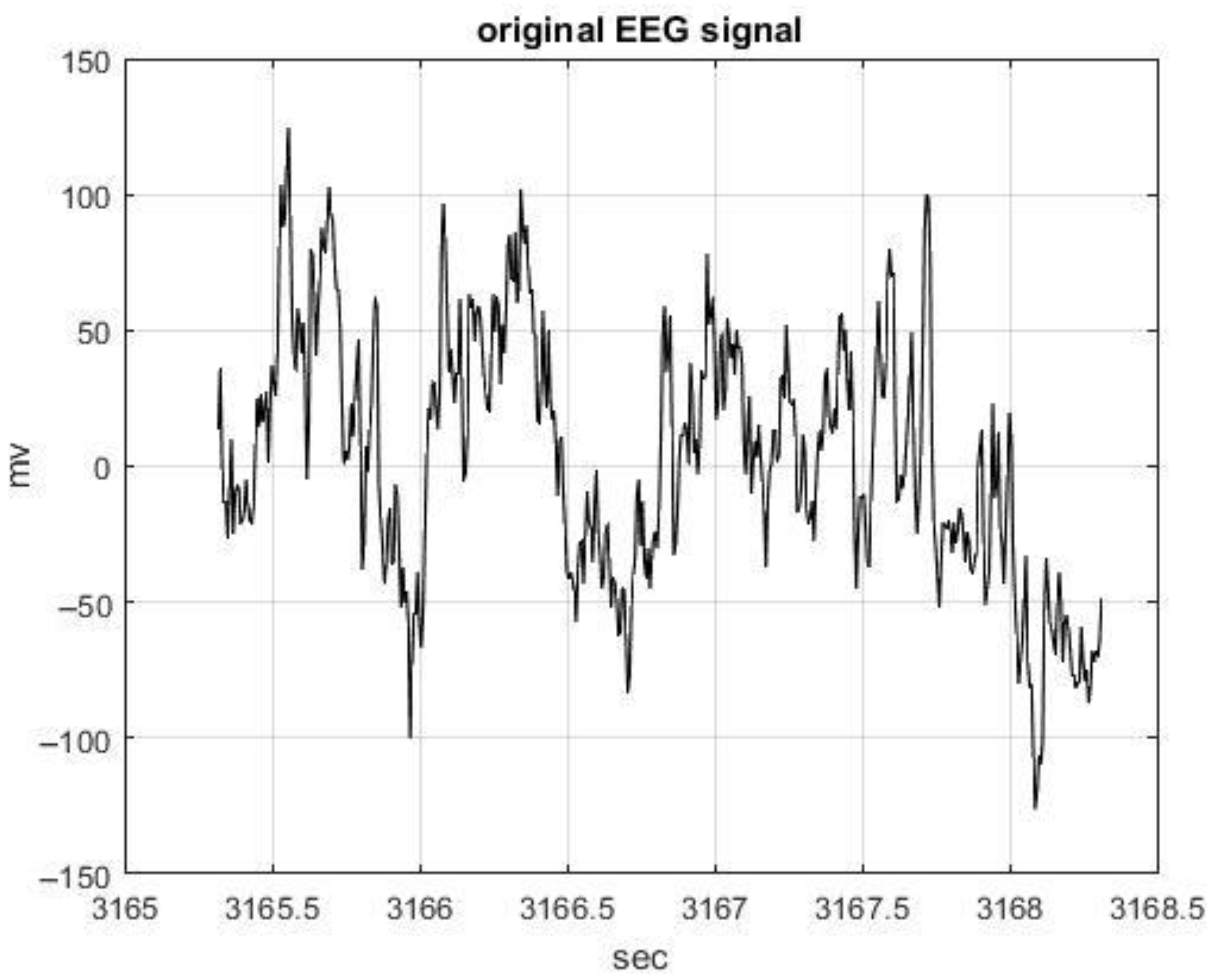
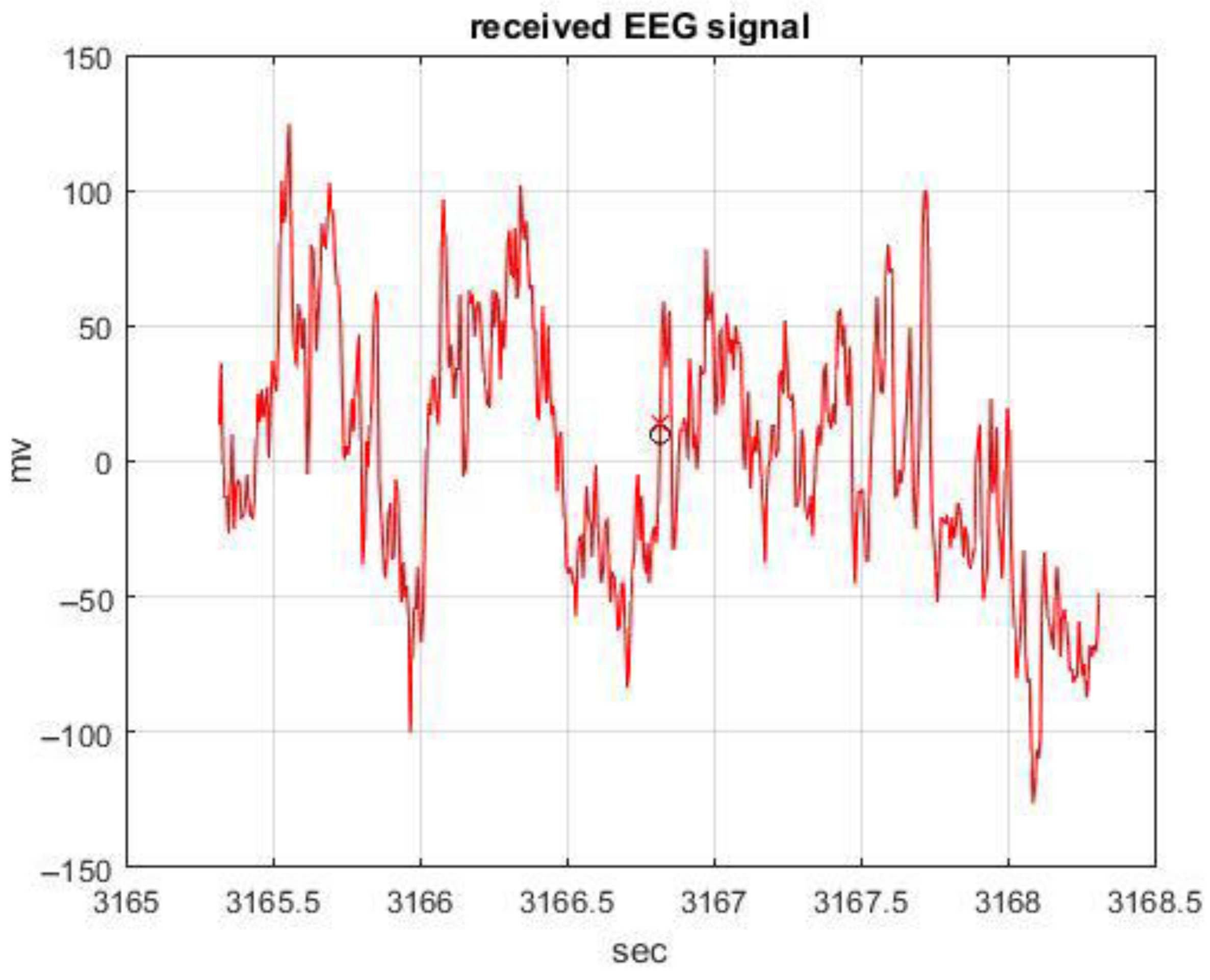
The BER, MSE, and PCC values of the proposed MECT with a CEE of 10% and a 15.00 dB SNR are 9.9777 × 10 8 ,   1.4369 × 10 5 , and 0.999999997622151 , respectively. The received EEG signal has only one amplitude error. Figure 8 illustrates the original EEG signal in the time interval from 3165.31875 s to 3168.31875 s. Figure 9 shows the received EEG signal with a CEE of 10% and an SNR of 14.51 dB in the time interval from 3165.31875 s to 3168.31875 s. The amplitude error occurs at 3166.81875 s, where the original and received EEG amplitudes are 10 mV and 14 mV, respectively. Simulation results show that the proposed GFDM-based DM MIMO MECT is suitable for EEG signal transmission and, can be integrated into mHealth, mobile telemedicine, and IoMT systems. Table 3 lists the technical notes of the advanced EEG transmission concepts.

5. Conclusions

This study proposed a 4 × 4 GFDM-based DM MIMO MECT for advanced mobile EEG signal transmission. LDPC channel coding, 4-QAM, and a PAM are integrated into the MECT to transmit EEG signals over the 3GPP CDL D channel model. The carrier frequency is 28 GHz, and mmWave communication can be achieved. The BER, MSE, and PCC values of the MECT with CEEs of 0%, 5%, and 10% were evaluated. The N 0 values of the proposed MECT with CEEs of 0%, 5%, and 10% with 40% PS are 0.0223, 0.0201, and 0.0181, respectively; the BER value is 9.9777 × 10 8 .
The simulation results show that the proposed MECT can achieve mobile EEG signal transmission with ultra-low power consumption, high data transmission rates, and low latency, demonstrating its suitability for integration into mHealth, mobile telemedicine, and IoMT systems. We have also highlighted clearly defined directions for future research, such as developing a GFDM-based DM-MIMO fixed-point simulation model in MATLAB 2024b to account for finite word length effects, followed by FPGA-based implementation and testing for real-time EEG signal transmission. With ongoing advancements in very large-scale integration technology, we anticipate that computational complexity and implementation costs of such systems can be significantly reduced. Furthermore, the proposed GFDM-based DM-MIMO MECT framework holds strong potential to improve the accuracy and power efficiency of real-time EEG sensors, which we identify as a key direction for future research.

Author Contributions

Conceptualization, C.-F.L.; methodology, C.-F.L. and K.-Y.C.; software, C.-F.L. and K.-Y.C. formal analysis, C.-F.L.; investigation C.-F.L. and K.-Y.C.; writing—original draft preparation, C.-F.L.; writing—review and editing, C.-F.L. All authors have read and agreed to the published version of the manuscript.

Funding

This research was funded by a grant from the Ministry of Education of Taiwan, MOE Teaching Practice Research Program, Research on the Model of Teaching Practices that Applies Cooperative Learning to a “Signal and System Experiment” Course, under contract number PEE1120238.

Institutional Review Board Statement

Not applicable.

Informed Consent Statement

Not applicable.

Conflicts of Interest

The authors declare no conflict of interest.

Abbreviations

Symbols
E S n EEG signal bit stream for the nth user
E S C n LDPC encoded EEG signal bit stream for the nth user
E S C P n , l S/P LDPC encoded EEG signal bit stream of the lth transmission antenna for the nth user
E S C P M n , l 4-QAM S/P LDPC encoded EEG signal symbol stream of the lth transmission antenna for the nth user
E S C P M M n , l GFDM-based 4-QAM S/P LDPC encoded EEG signal symbol stream of the lth transmission antenna for the nth user
E S C P M M P n , l GFDM-based 4-QAM S/P LDPC encoded EEG signal symbol stream of the lth transmission antenna for the nth user with the CP
E S C P M M P P n , l GFDM-based 4-QAM S/P LDPC encoded EEG signal symbol stream of the lth transmission antenna for the nth user with the CP and PAM
h n , l , p 3GPP CDL channel impulse response of the lth transmission antenna and the pth receiver antenna, for the nth user
S N R n , p , E E G , S ignal-to-noise ratio of EEG packets received by the pth receiver antenna for the nth user
X i Original EEG signal in the MECT
Y i Received EEG signal in the MECT
WLength of EEG signal.
r Pearson correlation coefficient
PSPower saving
σ n , l , p 2 Variance of additive white Gaussian noise of the l-th transmission antenna, and the p-th receiver antenna for the nth user.
μ n , l Transmission power weighting factor of the lth transmission antenna for the nth user
Abbreviations
3GPP3rd Generation Partnership Project
5G5th generation
6G6th generation
AWGNAdditive white Gaussian noise
BCIBrain-computer interface
BERBit error rate
BPSKBinary phase-shift keying
CDLCluster delay line
CEEChannel estimation error
CPCyclic prefix
CPMContinuous phase modulation
DMDirect mapping
DWDSDouble-window detection scheme
EEGElectroencephalography
FBMCFilter bank multicarrier
FERFrame error rate
FPGAField-programmable gate array
GFDMGeneralized frequency division multiplexing
IMIndex modulation
IoTInternet of Things
IoMTInternet of Medical Things
JPEGJoint Photographic Experts Group
LDPCLow-density parity-check
LOSLine-of-sight
MECTMobile EEG communication technology
MIMOMulti-input-multi-output
MSEMean square error
NLOSNon-line-of-sight
OFDMOrthogonal frequency division multiplexing
OOBOut-of-band
OQAMOffset QAM
OTFSOrthogonal time frequency space
OVSFOrthogonal variable spreading factor
PAMPower assignment mechanism
PCCPearson-correlation coefficients
PCEPerfect channel estimation
P/SParallel-to-serial
PSNRPeak signal-to-noise ratio
QAMQuadrature amplitude modulation
RCRate-compatible
ResNETResidual deep neural network
RRCRoot-raised cosine
RMSERoot mean square error
SESpectral efficiency
SNRSignal-to-noise ratio
STCSpace time code
S/PSerial-to-parallel
STBCSpace time block code
SERSymbol error rate
UAMCSUnderwater acoustic multimedia communication system

References

  1. Lin, X.; Zhang, J.; Lin, Y.; Kim, J. Fundamentals of 6G Communications and Networking; Springer Nature Switzerland AG: Cham, Switzerland, 2024; pp. 1–754. [Google Scholar]
  2. Meena, P.; Pal, M.B.; Jain, P.K.; Pamula, R. 6G Communication Networks: Introduction, Vision, Challenges, and Future Directions. Wirel. Pers. Commun. 2022, 125, 1097–1112. [Google Scholar] [CrossRef]
  3. Beyrouthy, T.; Mostafa, N.; Roshdy, A.; Karar, A.S.; Alkork, S. Review of EEG-Based Biometrics in 5G-IoT: Current Trends and Future Prospects. Appl. Sci. 2024, 14, 534. [Google Scholar] [CrossRef]
  4. Kumar, K.B.S.; Sujatha, B.R. FPGA Design of an Efficient EEG Signal Transmission Through 5G Wireless Network Using Optimized Pilot Based Channel Estimation: A Telemedicine Application. Wirel. Pers. Commun. 2022, 123, 3597–3621. [Google Scholar] [CrossRef]
  5. Lin, C.F.; Chang, S.H. Advanced Mobile Communication Techniques in the Fight Against the COVID-19 Pandemic Era and Beyond: An Overview of 5G/B5G/6G. Sensors 2023, 23, 7817. [Google Scholar] [CrossRef]
  6. Michailow, N.; Matthé, M.; Gaspar, I.S.; Caldevilla, A.N.; Mendes, L.L.; Festag, A.; Fettweis, G. Generalized Frequency Division Multiplexing for 5th Generation Cellular Networks. IEEE Trans. Commun. 2014, 62, 3045–3061. [Google Scholar] [CrossRef]
  7. Wang, Y.; Fortier, P. Performance Analysis of LDPC Coded GFDM Systems. IET Commun. 2022, 16, 1663–1673. [Google Scholar] [CrossRef]
  8. Li, Y.; Niu, K.; Dong, C. Polar-Coded GFDM Systems. IEEE Access 2019, 7, 149299–149307. [Google Scholar] [CrossRef]
  9. Ssimbwa, J.; Lim, B.; Ko, Y.C. GFDM Frame Design for Low-latency Industrial Networks. Journa Commun. Netw. 2022, 24, 336–346. [Google Scholar] [CrossRef]
  10. Wang, H.F.; Ueng, F.B.; Chiang, C.T. High Spectral Efficiency and Low Error Rate MIMO–GFDM for Next-Generation Communication Systems. IEEE Trans. Veh. Technol. 2022, 71, 503–517. [Google Scholar] [CrossRef]
  11. Juajinoy, J.L.C.; Cal-Braz, J.; Neto, R.S. Detection Strategies for MIMO-GFDM-IM System. IET Commun. 2025, 19, e70016. [Google Scholar] [CrossRef]
  12. Tasadduq, I.A. CPM-GFDM: A Novel Combination of Continuous Phase Modulation and Generalized Frequency Division Multiplexing for Wireless Communication. Appl. Sci. 2023, 13, 854. [Google Scholar] [CrossRef]
  13. Kalsotra, S.; Singh, A.K.; Joshi, H.D. Performance analysis of space time coded generalized frequency division multiplexing system over generalized fading channels. Trans. Emerg. Telecommun. Technol. 2022, 13, e4423. [Google Scholar] [CrossRef]
  14. Choa, H.; Ahnb, J.M.; Nohc, J.H.; Song, H.Y. Some new LDPC-coded orthogonal modulation schemes for high data rate transmissions in navigation satellite systems. ICT Express 2024, 10, 588–593. [Google Scholar] [CrossRef]
  15. Kwak, W.S.; Kim, J.W. Design of LDPC code for uncorrelated Rayleigh fading channel using modified outage probability. ICT Express 2025, 11, 442–447. [Google Scholar] [CrossRef]
  16. Hyla, J.; Sułek, W.; Zydorczyk, W.; Dziczkowski, L.; Filipowski, W. Efficient LDPC Encoder Design for IoT-Type Devices. Appl. Sci. 2021, 12, 2558. [Google Scholar] [CrossRef]
  17. Liu, J.; Hao, Z.; Zhao, L.; Lian, J.; Jun Tao, J.; Fan, Y.; Feng, Q. A Low Valid Throughput Loss LDPC Codec Architecture with Variable Code Rate. IEEE Trans. Circuits Syst.—II Express Briefs 2024, 71, 2644–2648. [Google Scholar] [CrossRef]
  18. Cummins, A.D.; Mitchell, D.G.M.; Perrins, E. Rate-Compatible, Bandwidth-Efficient, Low-Density Parity-Check (LDPC) Codes for Aeronautical Telemetry. Entropy 2024, 26, 1045. [Google Scholar] [CrossRef] [PubMed]
  19. Gunturu, A.; Godala, A.R.; Sahoo, A.K.; Chavva, A.K.R. Performance Analysis of OTFS Waveform for 5G NR mmWave Communication System. In Proceedings of the IEEE Wireless Communications and Networking Conference (WCNC), Nanjing, China, 29 March–1 April 2021. [Google Scholar]
  20. Usatyuk, V.S.; Egorov, S.I. 2D/3D ResNet Deep Neural Network for 4G and 5G NR Wireless Channel Estimation. In Proceedings of the IEEE 25th International Conference on Digital Signal Processing and its Applications (DSPA), Moscow, Russia, 29–31 March 2023. [Google Scholar]
  21. Earlea, B.; Al-Habashna, A.; Wainera, G.; Lic, X.; Xuec, G. Machine Learning-Based Small-Scale Parameter Extraction for Improved Wireless Channel Model Fidelity. In Proceedings of the IEEE Annual Modeling and Simulation Conference (ANNSIM), Washington, DC, USA, 20–23 May 2024. [Google Scholar]
  22. Jiang, T.; Zhang, J.; Pan Tang, P.; Tian, L.; Zheng, Y.; Dou, J.; Asplund, H.; Raschkowski, L.; Errico, R.; Tommi Jämsä, T. 3GPP Standardized 5G Channel Model for IIoT Scenarios: A Survey. IEEE Internet Things J. 2021, 8, 8799–8815. [Google Scholar] [CrossRef]
  23. Lin, C.F.; Wu, C.F.; Hsieh, C.L.; Chang, S.H.; Parinov, I.A.; Shevtsov, S. Generalized Frequency Division Multiplexing-Based Low-Power Underwater Acoustic Image Transceiver. Sensors 2022, 22, 313. [Google Scholar] [CrossRef]
  24. 5G Study on Channel Model for Frequencies from 0.5 to 100 GHz; 3GPP TR 38.901; Hanoi University of Technology: Hanoi, Vietnam, 2020.
  25. EEG Motor Movement/Imagery Dataset. Available online: https://physionet.org/content/eegmmidb/1.0.0/ (accessed on 26 August 2025).
  26. Lin, C.T.; Wang, Y.; Chen, S.F.; Huang, K.C.; Liao, L.D. Design and Verification of a Wearable Wireless 64-Channel High-Resolution EEG Acquisition System with Wi-Fi Transmission. Med. Biol. Eng. Comput. 2023, 61, 3003–3019. [Google Scholar] [CrossRef]
  27. Santhosh Kumar, K.B.; Sujatha, B.R.; Sushma, N. Machine Learning-based Channel Estimation for EEG Signal Transmission in MIMO-OFDM System. In Proceedings of the IEEE International Conference on Recent Advances in Information Technology for Sustainable Development (ICRAIS), Manipal, India, 6–7 November 2024. [Google Scholar]
  28. Revanna, B.R.; Akhila, S.; Santhosh Kumar, K.B.; Sushma, N.; Radhika, K.A.; Ghouse Ahamed, Z. EEG Transmission over 6G Optimized Pilot-Based Channel Estimation. In Proceedings of the IEEE International Conference on Circuits, Control, Communication and Computing (I4C), Bangalore, India, 4–5 October 2024. [Google Scholar]
  29. Kanemoto, D.; Takimoto, E.; Hirose, T. Development of Low-power and High-accuracy Wireless EEG Transmission System Using Compressed Sensing with an EEG Basis. In Proceedings of the IEEE International Conference on Circuits, and Systems (ISCAS), London, UK, 25–28 May 2025. [Google Scholar]
  30. Lin, C.F.; Chang, K.T. A Power Assignment Mechanism in Ka-band OFDM-based Multi-satellites Mobile Telemedicine. J. Med. Biol. Eng. 2008, 28, 17–22. [Google Scholar]
  31. Lin, C.F.; Hung, S.I.; Chiang, I.H. An 802.11n wireless local area network transmission scheme for wireless telemedicine application. Proc. IMechE Part H J. Eng. Med. 2010, 224, 1201–1208. [Google Scholar] [CrossRef] [PubMed]
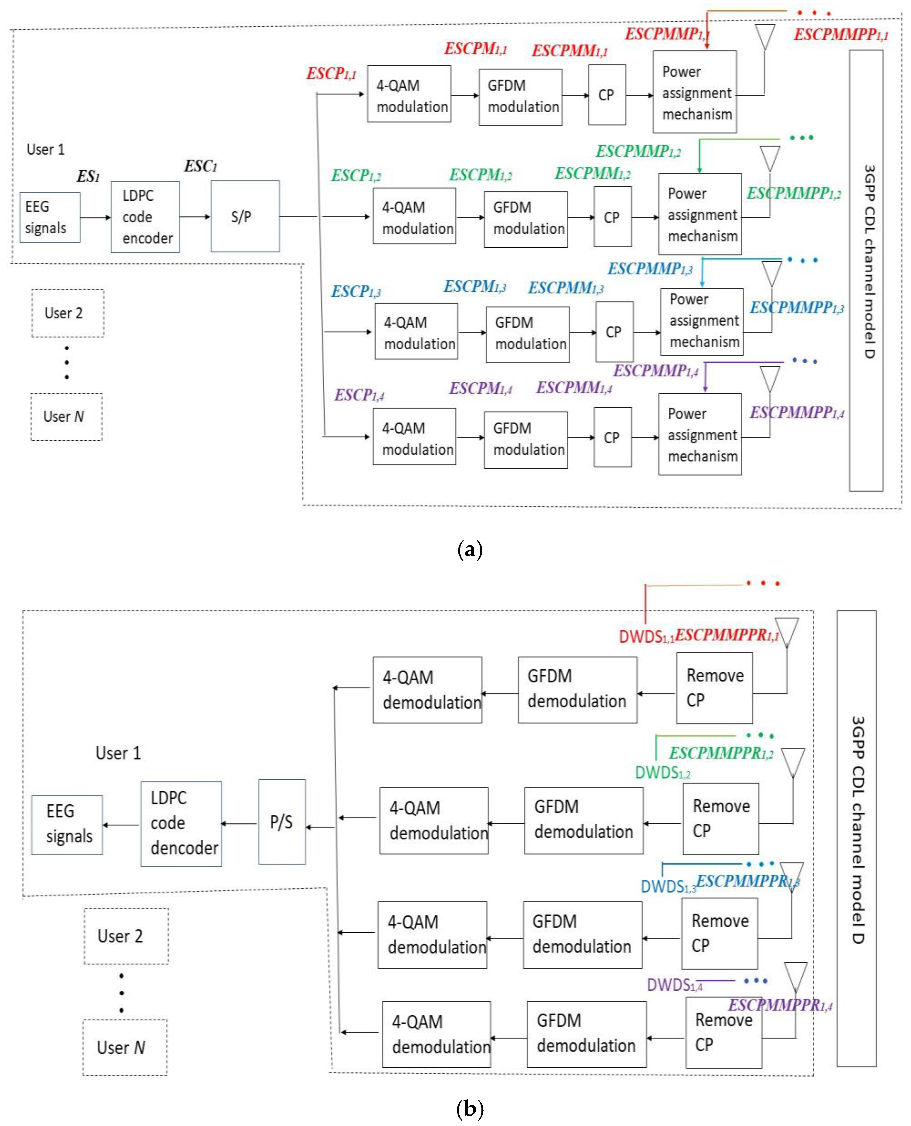
Figure 1. Proposed GFDM-based DM MIMO MECT. (a) Transmitter; (b) receiver.
Applsci 15 09451 g001
Figure 2. BER performance of the 4 × 4 GFDM-based DM MIMO MECT for the nth user. (blue: PCE; green: CEE of 5%; red: CEE of 10%).
Applsci 15 09451 g002
Figure 3. MSE performance of the 4 × 4 GFDM-based DM MIMO MECT for the nth user. (blue: PCE; green: CEE of 5%; red: CEE of 10%).
Applsci 15 09451 g003
Figure 4. PCC performance of the 4 × 4 GFDM-based DM MIMO MECT for the nth user. (blue: PCE; green: CEE of 5%; red: CEE of 10%).
Applsci 15 09451 g004
Figure 5. PS performance of the 4 × 4 GFDM-based DM MIMO MECT for the nth user. (blue: PCE; green: CEE of 5%; red: CEE of 10%).
Applsci 15 09451 g005
Figure 6. Illustration of original EEG signal (5803.2125–5806.2125 s).
Applsci 15 09451 g006
Figure 7. Illustration of received EEG signal with CEE of 10%, and SNR of 14.51 dB. (5803.2125–5806.2125 s).
Applsci 15 09451 g007
Figure 8. Illustration of original EEG signal (3165.31875–3168.31875 s).
Applsci 15 09451 g008
Figure 9. Illustration of the received EEG signal with CEE of 10%, and SNR of 15.00 dB. (3165.31875–3168.31875 s).
Applsci 15 09451 g009
Table 1. Simulation parameters of the proposed 4 × 4 GFDM-based DM MIMO MECT.
TechnologyTechnological Characteristics
GFDM modulationMichailow et al. [6]
Channel model3GPP CDL channel model D (LOS)
Carrier central frequency28 GHz
Mobile speed400 km/h
MIMO4 × 4 DM
Number of subcarriers (B)128
Number of subsymbols (C)9
Filter methodRRC
Roll-off factor0.1
Modulation4-QAM
Channel coding(2000, 1000) LDPC code
Transmission mediaECG signals
Power weighting factors15/30, 16/30, …, 30/30
BER limits for EEG transmission 10 7
EEG test transmission signalsEEG Motor Movement/Imagery
Dataset [25]
Table 2. The SNR, BER, MSE, and PCC values of the proposed MECT with CEEs of 0%, 5%, and 10%.
CEEs (%)SNR (dB)BERMSEPCC
011.00 8.68 × 10 5 3.360.99944
511.00 2.60 × 10 4 24.250.99600
1011.00 6.42 × 10 4 68.040.98898
013.51 1.20 × 10 6 6.51 × 10 2 0.999989228
513.51 3.99 × 10 6 3.91 × 10 1 0.999935264
1013.51 1.05 × 10 5 1.150.999810395
014.10 9.98 × 10 8 1.44 × 10 5 0.999999999762218
514.51 9.98 × 10 8 1.44 × 10 5 0.999999998
1015.00 9.98 × 10 8 1.44 × 10 5 0.999999997622151
Table 3. Technical notes on the advanced EEG transmission concepts.
ReferencesTechnological Notes
Lin et al. [26]
  • High-resolution (24-bit);
  • Multichannel;
  • EEG BCI-based system-on-a chip;
  • WiFi;
  • Heavy and large BCI-based EEG signals.
Santhosh Kumar et al. [27]
  • OFDM-MIMO;
  • Turbo channel coding;
  • Machine learning-based channel estimation scheme;
  • Change the transmitter and receiver number to decrease transmission BERs;
  • The high accuracy, and low latency EEG signal transmissions.
Revanna et al. [28]
  • Reliable and real-time EEG signal transmission system;
  • High bandwidth and low latency capabilities;
  • 6G transmission technology;
  • Pilot-based channel estimation method;
  • High channel estimation accuracy;
  • Received EEG signal quality can be improved.
Kanemotoet al. [29]
  • Wireless EEG transmission technology;
  • PS, high compression and high-accuracy reconstruction;
  • Compressed sensing with random undersampling;
  • Block sparse Bayesian learning.
Kumaret al. [4]
  • Hybrid multiresolution discrete wavelet transform;
  • Turbo channel coding;
  • GFDM-IM modulation;
  • Field-programmable gate array (FPGA)-based EEG signal transmission system;
  • Simulated under Xilinx platform with Verilog coding;
  • The performances of BER, area and frequency were evaluated.
Lin et al. [30]
  • A Ka-band OFDM low-Earth-orbit multi-satellite telemedicine system;
  • STBC and DM transmission strategies;
  • PAM;
  • K = 9 1/2 (561, 753) convolution code with soft decoding, and K = 9 1/3 (557, 663, 771) convolutional code with soft decoding;
  • An open area channel model in the Ka band was adopted to operate under clear sky, light rain, medium light rain, and medium heavy rain condition.
Lin et al. [31]
  • mHealth;
  • Home care and hospitals to meet quality of service requirements of wireless telemedicine applications;
  • A robust IEEE 802.11n wireless local area network transmission system;
  • Provide effective wireless telemedicine services, operating anytime, anywhere.
The proposed method
  • GFDM;
  • 4 × 4 DM-MIMO;
  • (2000, 1000) LDPC;
  • MECT;
  • 3GPP CDL channel model D;
  • 28 GHz;
  • Low power consumption;
  • High transmission data rates;
  • Low latency;
Disclaimer/Publisher’s Note: The statements, opinions and data contained in all publications are solely those of the individual author(s) and contributor(s) and not of MDPI and/or the editor(s). MDPI and/or the editor(s) disclaim responsibility for any injury to people or property resulting from any ideas, methods, instructions or products referred to in the content.