Article

Structural Optimization of a Pipeline Savonius Hydro Turbine Based on Broad Learning

1
College of Marine Equipment and Mechanical Engineering, Jimei University, Xiamen 361021, China
2
Key Laboratory of Energy Cleaning Utilization and Development of Fujian Province, Jimei University, Xiamen 361021, China
*
Author to whom correspondence should be addressed.
Appl. Sci. 2025, 15(16), 9181; https://doi.org/10.3390/app15169181
Submission received: 4 July 2025 / Revised: 16 August 2025 / Accepted: 17 August 2025 / Published: 20 August 2025
(This article belongs to the Section Fluid Science and Technology)

Abstract

Utilizing pipeline Savonius hydro turbines driven by the pressure difference in water flow in the irrigation pipelines to generate electricity can achieve stable and reliable charging of the sensor battery, thereby addressing autonomous energy supply concerns. However, due to the low energy capture efficiency of the Savonius turbine with a small pressure difference, it is necessary to optimally design the internal flow channel structure to improve its efficiency and achieve a more miniaturized overall equipment, which has extremely high engineering application value. This study investigates the Savonius turbine, installed within the irrigation pipeline operating under specific conditions (diameter: 60 mm; flow rate: 15 m3/h; inlet pressure: 0.2 MPa; outlet pressure ≤ 0.05 MPa). A validated Computational Fluid Dynamics numerical model was developed to generate 200 datasets for a subsequent structural optimization process utilizing a Bayesian-optimized broad learning technique. The optimal structural parameters for maximum efficiency are a deflector angle of 10°, an aspect ratio of 0.775, and three blades, resulting in a maximum efficiency of 21.73% at a rotational speed of 1098 r/min. For the maximum power coefficient, the optimal combination is a deflector angle of 10°, a height-to-diameter ratio of 0.9, and three blades, yielding a peak power coefficient of 0.1859 at a rotational speed of 600 r/min.

1. Introduction

The continuous advancement of technology has facilitated the widespread adoption of various efficient smart irrigation methods in modern agriculture, including sprinkler irrigation, drip irrigation, and low-pressure pipeline irrigation [1,2,3,4]. Advanced smart irrigation systems typically incorporate automated control systems integrating the Internet of Things (IoT), sensor technology, and remote control capabilities [5,6,7]. These systems primarily rely on sensor nodes, distributed along pipelines, to collect information and transmit it to a central control unit [8,9,10]. Currently, the power supply for these sensors is predominantly dependent on battery power, encompassing rechargeable lithium-ion batteries and single-use lead-acid batteries. However, the operational lifespan and capacity limitations of batteries necessitate periodic replacement or maintenance, thereby significantly increasing the maintenance burden of irrigation systems. This is particularly pronounced when some sensors are situated in locations with limited accessibility, such as deep underground or on steep cliffs, escalating maintenance costs and posing significant challenges. Therefore, ensuring reliable and stable energy supply to the various sensors within the system is paramount for guaranteeing the long-term operational stability of smart irrigation systems [11,12,13,14,15]. In this context, harnessing the water flow pressure differential between municipal water supply pipelines and the end-points of sprinkler irrigation systems for power generation has emerged as a promising technical avenue [16]. Traditionally, this pressure differential is dissipated through pressure-reducing valves, resulting in energy wastage. In contrast, employing hydrokinetic turbines within pipelines offers a viable method for recovering this otherwise lost energy, which can then be used to charge lithium-ion batteries for the sensors, ensuring their consistent operational readiness without the need for manual charging interventions.
The design concept of the Savonius turbine is derived from the vertical-axis wind turbine proposed by Finnish engineer Savonius [17]. Due to its advantageous characteristics, including favorable starting torque, low noise levels, structural simplicity, and low manufacturing costs, vertical-axis wind turbines are currently utilized for micro-wind power generation at the level of tens of kilowatts. To adapt this technology for energy harvesting from residual pressure within circular water supply pipelines, the design principles of vertical-axis wind turbines have been adopted and applied to micro-hydrokinetic turbine generation, leading to the development of the vertical-axis Savonius hydro turbine [18,19]. This kind of turbine is well-suited for providing continuous energy supply to sensors within water supply and irrigation systems. The Savonius hydro turbine operates through the differential drag between the concave and convex portions of the advancing blades, causing them to rotate and perform work. However, the convex portion of the returning blades generates a negative energy capture region during rotation [20,21], thereby substantially impairing its power generation efficiency. Also, the inherent losses within the Savonius hydro turbine and the low utilizable water flow pressure differential result in energy capture efficiencies considerably lower than those of Savonius wind turbines [17]. To improve the capture efficiency of Savonius hydro turbines, some scholars have focused on the relationship between the structural parameters (such as deflector angle, aspect ratio (AR), blade numbers, blade shape, etc.) and their energy capture efficiency.
The deflector of a pipeline Savonius hydro turbine not only facilitates the conversion of fluid pressure energy into kinetic energy, thereby maximizing the rotor’s capture of incoming flow energy, but also reduces the reverse torque on the returning blades, consequently decreasing blade rotational drag and enhancing the power coefficient [22]. The optimization of deflector components includes their shape and deflector angle. Rehman et al. [23] found that a crescent-shaped deflector placed upstream of the returning blade in a Savonius hydrokinetic turbine significantly improved its performance. Chen et al. [16] designed a micro-pipeline Savonius turbine for a municipal water supply pipeline with a diameter of 100 mm. To improve the output efficiency, they designed four different deflector shapes. It indicated that a slanted eye-shaped block was most effective in enhancing turbine performance, achieving a maximum output power of 32 W. Based on the turbine structure by Chen et al. [16], Payambarpour et al. [24] analyzed the effects of different deflector angles. The results revealed that, under a constant pressure drop, an increase in the deflector angle leads to an increase in flow velocity but a decrease in flow rate, causing the turbine torque to initially increase and then subsequently decrease. This implies that increasing the deflector angle beyond a certain degree will not only degrade the turbine’s starting performance but also reduce its output power.
In addition, the rotor height can influence the flow capacity of the pipeline when its diameter is constant. Rotors of varying heights induce different levels of blockage within the pipeline, resulting in different degrees of head loss, which consequently causes substantial variations in the rotor’s energy characteristics [24,25]. Payambarpour et al. [24] increased the rotor AR from 0.4 to 0.9 and observed that an increase in rotor height enhances the contact area between the rotor and the fluid, resulting in an increased pressure drop, and that efficiency increases with the AR value. The maximum efficiency was 10% when AR = 0.9. Lv et al. [25] applied Savonius rotors in ball valves and analyzed the performance of rotors with ARs of 0.8, 0.85, and 0.9. The results indicated that, under the same valve opening conditions, the rotor with AR = 0.8 exhibited the smallest tip clearance and minimal leakage. This implies that more of the water energy was effectively converted into mechanical energy within the flow channel, leading to the highest shaft power and efficiency, recorded at 78.6 W and 8.65%, respectively.
The number of blades also influences the power and efficiency of Savonius turbines. Regarding the optimal blade number for Savonius turbines, there is no consistent conclusion in the existing studies. Thiyagaraj et al. [26] found that when the number of blades exceeds two, an increased number of blades leads to greater rotor rotational resistance, which impairs the effective flow of the working fluid within the turbine. When the blade number ranges from two to six, the two-bladed Savonius turbine has the maximum power coefficient, reaching 0.105. However, Chen et al. [16] increased the blade number of the rotor from 3 to 24 and found that a turbine with 12 blades, combined with a hollow shaft and short slanted eye-shaped blocks, could achieve a maximum power output of 88.2 W. The discrepancy in the conclusions of these two studies likely arises from the use of a traditional Savonius rotor with endplates by Thiyagaraj et al. [26], while Chen et al. [16] utilized a spherical Savonius rotor, adapted for small-diameter pipelines, and also the fact that they were testing different application scenarios. Thus, numerous factors influence the performance of Savonius rotors, and a single-factor analysis may not be comprehensive.
Furthermore, while many other blade shapes for Savonius rotors have been explored, the semi-circular blade shape remains the most common [22,27,28]. For Savonius rotors with larger diameters, the increased contact area with the fluid means that changes in the blade shape have a significant impact on turbine performance. Saad et al. [29] modified the twist angle of the blades of a Savonius wind turbine of 400 mm diameter. They found that with a twist angle of 45°, the water flow acted directly on the concave surface of the advancing blade, resulting in an increase in the total pressure. This, in turn, caused a significant rise in the net torque generated by the rotor compared to other angles. In contrast, for smaller-sized Savonius rotors, the impact of blade shape on their performance is less significant. Talukdar et al. [27] modified the blade profile of a 250 mm diameter Savonius turbine intended for river applications to an elliptical shape, but found that intense turbulence occurred at the tip and trailing edge of the elliptical blade, which diminished the performance of the elliptical-blade turbine. As a result, the Cpmax of the two-bladed semi-circular turbine is 28.6% higher than that of the two-bladed elliptical turbine.
The above-mentioned research has demonstrated that factors such as the deflector angle [16,23,24], aspect ratio (AR) [24,25], blade numbers [16,26,27,30,31], blade shape [29,32], and rotational speed [33,34] significantly influence energy capture efficiency. Obviously, the complex nature of the internal flow within hydro turbines, along with the numerous interacting geometrical factors influencing the Savonius turbine performance, collectively determine the operating efficiency and performance of these turbines. The average efficiency level of these turbines under varying operating conditions typically remains between 10% and 20%, as detailed in Table 1. The majority of studies shown in Table 1 have examined the effects of a single factor variation under specific conditions for a particular turbine configuration. Indeed, this single-factor approach possesses inherent limitations. Some literature has moved away from single-factor analysis and has adopted orthogonal methods to couple multiple factors for a more comprehensive numerical simulation or experimental analysis [16,25]. However, the workload of multi-factor analysis is enormous, and the technical methods that only enumerate a limited number of multi-factor combinations without enabling continuous optimization search across the entire variable domain have obvious limitations. Using the former approach carries a high probability of missing the optimal results.
With the rise in machine learning, it has found good application in fluid machinery, including flow field prediction [35,36,37,38,39]. Hasanzadeh et al. [35] pioneered the use of a broad learning predictive model based on artificial neural networks, and introduced dimensionless variables to optimize seven key factors affecting the performance of a 100 mm diameter pipeline turbine. This study suggested that when the head loss is less than 5 m and within a constrained flow rate range, the power of this pipeline turbine could be expected to reach 200 W, with an efficiency exceeding 33%, based on theoretical predictions and model analysis. This predicted performance represents a substantial improvement compared with that of the previous drag-type pipeline turbines. However, the reliability of the numerical calculation model used in Ref [35] to generate the large dataset was not verified experimentally, nor was the optimization result. Due to the complexity of turbulent flow, Chen et al. [16] indicated that the numerical results obtained for the full flow path of the turbine exhibit substantial errors. However, this is a prerequisite for machine learning accuracy. Compared with the complex mapping relationships of traditional deep learning, in recent years, novel neural network frameworks, such as broad learning, have a flattened structure design that endows them with faster learning speed and good generalization capability. Broad learning models not only surpass deep learning in flow field prediction accuracy but also exhibit significantly faster prediction speeds when dealing with complex tasks [40,41].
In this work, a combined approach of Computational Fluid Dynamics (CFD) numerical simulation, broad learning systems, and experimental validation was applied to conduct structural optimization of a pipeline Savonius turbine installed at the end of an irrigation water supply pipeline under specific operating conditions (diameter: 60 mm; fixed flow rate: 15 m3/h; inlet pressure: 0.2 MPa; outlet pressure ≤ 0.05 MPa). Four key factors that most significantly influence turbine performance were considered within the scope of this study, encompassing three geometric variables—deflector angle, aspect ratio, and the blade number—as well as the operational variable of rotational speed. Initially, a uniformly distributed dataset of these four variables was generated using a Sobol sequence generator, and numerical simulations were performed using ANSYS-CFX 2020 R1 to obtain the required data. Subsequently, a prototype turbine was designed and fabricated, and a test rig was established for experimental validation. Experimental data were compared with the numerical simulation results to verify the accuracy of the numerical model. Finally, a predictive model of turbine efficiency and power coefficient within the pipeline was developed using broad learning based on Bayesian optimization. This model was used to perform multi-objective optimization of turbine performance, and the optimized results were further verified through the experimental results.

2. Numerical Simulation Methodology

2.1. Design Parameters

The internal diameter of the pipeline Savonius hydro turbine is 60 mm, and its key components are the deflector and the vertical-axis rotor, as shown in Figure 1. The deflector can change the direction and speed of the water flow, converting the pressure energy of the water into kinetic energy and precisely impacting the leading blades, preventing the incoming flow from impacting the back of the return blades, and reducing the reverse torque on the return blades. Unlike the traditional semicylindrical Savonius blades, the blade shape in the pipeline is more complex, with a structure that approximates a sphere after cutting off part of the top and bottom. The runner blades are shaped as a hemispherical surface, with the center of the circle located on the diameter of the rotor, ensuring balance during rotation. The side is a circular arc with a specific curvature, which allows the rotor to reduce resistance and improve overall efficiency during high-speed rotation. The structural design parameters of the Savonius turbine are shown in Table 2.

2.2. Computational Domain

The computational domain for the numerical simulations consists of an inlet pipe, a deflector region, a rotating domain, and an outlet pipe, as illustrated in Figure 2. Although the three-dimensional models of the various turbines under investigation differ, the overall structure of the computational domain within which these turbines are placed remains consistent across all numerical simulations.

2.3. Turbulence Model and Boundary Conditions

The internal flow field of the Savonius hydro turbine was numerically simulated using ANSYS-CFX. Given the complex nature of the flow within the turbine, and the presence of intricate vortex structures and flow separation around the blades, the Reynolds-Averaged Navier–Stokes (RANS)-based RNG k-ε turbulence model was selected for this study. The inlet of the computational domain was defined as a pressure inlet, with all inlet pressures set to 0.2 MPa. The outlet of the computational domain was defined as a mass flow rate outlet, with a flow rate of 15 m3/h. The no-slip boundary condition was applied to all walls, and the frozen rotor approach was adopted for the simulation. Given the complexity of the internal flow within hydrokinetic turbines, where the flow around the blades is frequently accompanied by intricate vortex structures and flow separation, the RNG k-ε model was employed due to its robust handling of rotational effects and its enhanced ability to capture these flow characteristics, thereby improving the accuracy of the simulation [16].

2.4. Mesh and Independence Verification

The computational domain of the investigated models was meshed using ICEM-CFD with a highly adaptable unstructured tetrahedral mesh. Three layers of boundary layer mesh were added to the near-wall regions of the pipe. Furthermore, local mesh refinement was applied to the areas around the rotor, the fixed deflectors, and the interfaces. This ensured a denser mesh in critical areas to capture complex flow details. As an example, Figure 3a shows the meshed computational domain for a rotor with an aspect ratio of 0.7 and 5 blades. To verify mesh independence, the turbine pressure drop, efficiency, and power coefficient were calculated for six different mesh densities, as shown in Figure 3b. The results indicate that these three parameters become stable when the mesh count reaches 4 million.

2.5. Experiment and Numerical Model Reliability

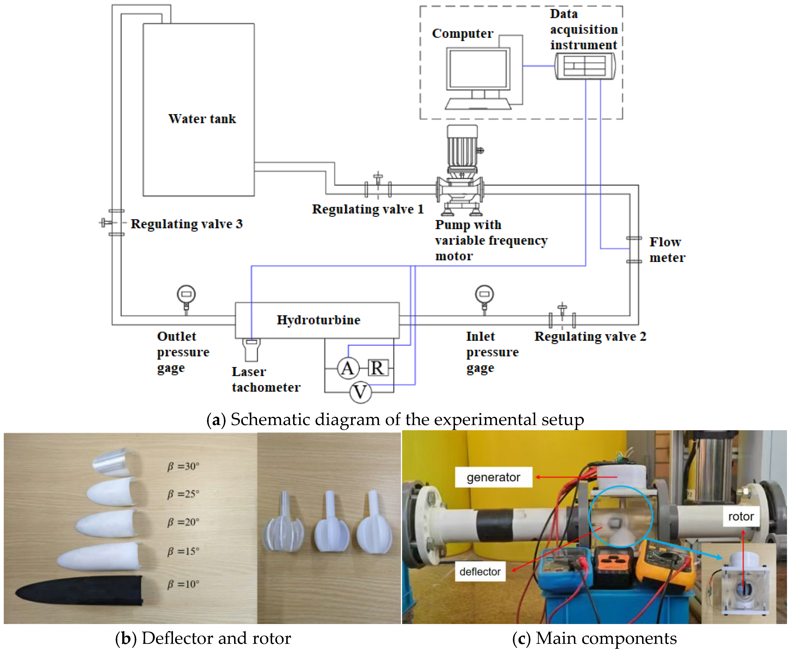
The overall experimental setup is shown in Figure 4. The pressure circulation system of this experiment comprises the variable frequency booster pump, the water tank, and the PVC piping. A variable frequency booster pump, model CHL25-2 (Shanghai People Pump Factory Co., Ltd., Shanghai, China), was used to provide the required operating conditions for the experiment. The pump is designed for a flow rate of 25 m3/h and a head of 22 m, thus meeting the experimental conditions (inlet pressure of 0.2 MPa and flow rate of 15 m3/h). The variable frequency controller enables the pump to operate under conditions lower than its design specifications while maintaining good pressure regulation. Both the inlet valve of the pump and the outlet valve of the Savonius turbine were used to regulate the pressure and flow rate of the entire experimental system, ensuring consistent operating conditions when testing different deflectors and rotors. The end of the experimental system was equipped with a water tank open to the atmosphere, creating a self-circulating operating system.
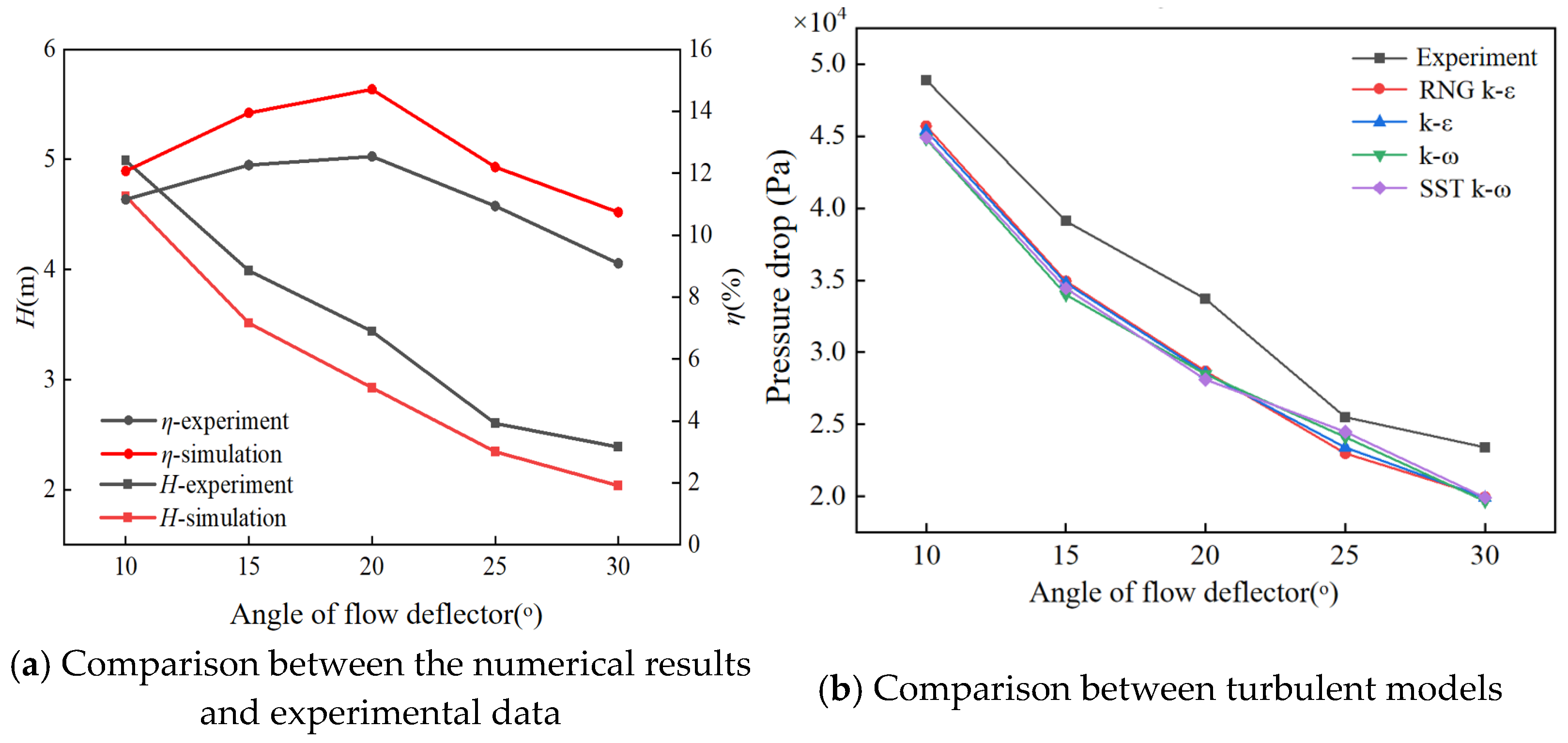
With a fixed flow rate of 15 m3/h and an inlet pressure of 0.2 MPa, experiments were nonpipelined to obtain the pressure drop and efficiency for a rotor with an aspect ratio of 0.7, 5 blades, and deflector angles of 10°, 15°, 20°, 25°, and 30°. The comparison between the numerical simulation results and the experimental results is shown in Figure 5a. A comparative analysis of four different turbulence models (RNG k-ε, Standard k-ε, SST k-ω, and Standard k-ω) was performed to evaluate the accuracy of the simulation. Figure 5b indicates that the RNG k-ε model produced a trend most closely aligned with the experimental data. As evident in Figure 5a, the numerical simulation results for head loss and efficiency exhibit trends that are in good agreement with the experimental data. Under the design operating conditions, the maximum discrepancies between the experimental and simulated values for head loss and efficiency were 17.51% and 18.26%, respectively. Given that these errors are within 20%, which is within the acceptable range for engineering applications, the theoretical numerical model established in this study can be considered reliable.

3. Results

3.1. Single-Factor Analysis

3.1.1. Effects of Deflector Angle

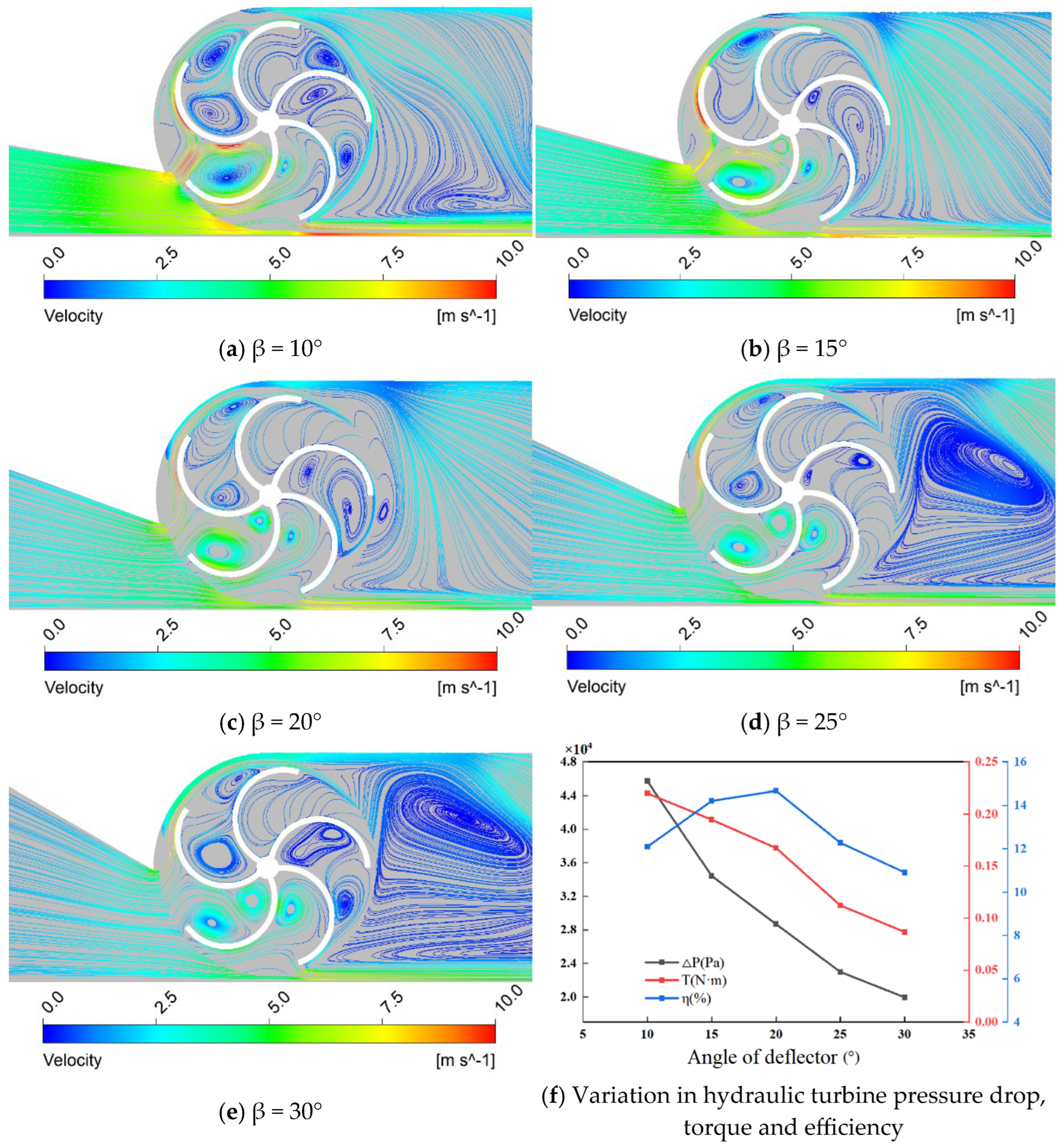
Based on the above validated numerical model, Figure 6a–e present the streamline plots for deflector angles of 10°, 15°, 20°, 25°, and 30°. When the deflector angle is 10°, the water flow impacts the blades and forms a vortex at the rotor outlet, which increases pressure loss. As the deflector angle increases, the streamlines become smoother, and the pressure loss gradually decreases. However, when the deflector angle increases to 25°, a larger vortex forms at the rotor outlet. Moreover, with the increase in deflector angle, the pressure on the back of the blades also gradually increases, reducing the drag difference between the concave and convex surfaces of the blades. This weakens the interaction between the water flow and the blades, subsequently decreasing the torque and reducing efficiency. This indicates that both excessively large and excessively small deflector angles can adversely affect the hydraulic performance of the Savonius hydrokinetic turbine. Furthermore, Figure 6f illustrates the variations in turbine pressure drop, torque, and efficiency at different deflector angles. As shown in Figure 6f, both the pressure drop and torque continuously decrease with increasing deflector angle, while the efficiency exhibits a trend of first increasing and then decreasing.

3.1.2. Effects of Aspect Ratio

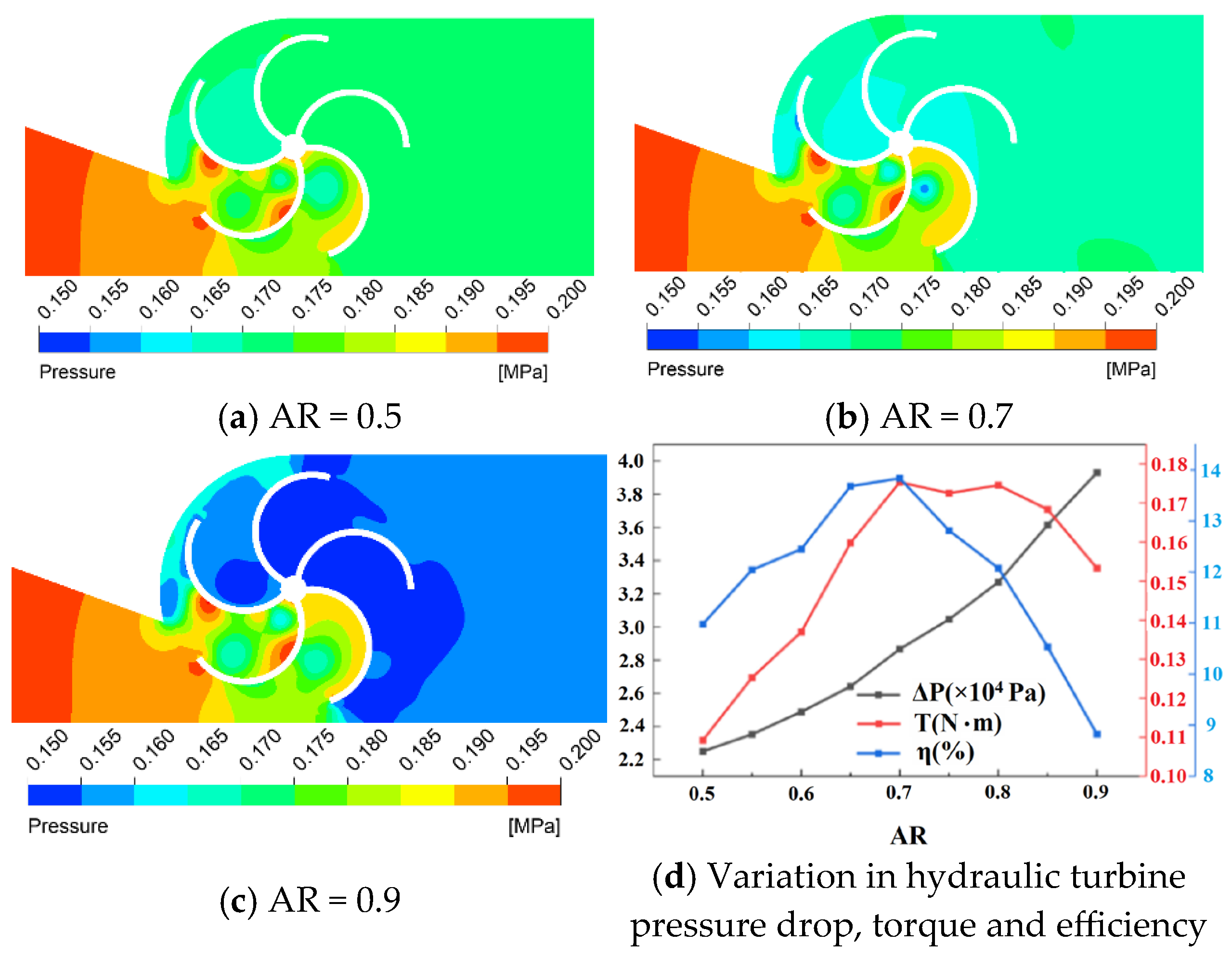
To investigate the influence of aspect ratio on the performance of the Savonius hydro turbine, the aspect ratio was varied from 0.5 to 0.9, while maintaining a fixed deflector angle of 20°, a blade count of 5, and constant operating conditions. Figure 7a–c present the pressure contour plots at the central cross-section of the rotor for aspect ratios of 0.5, 0.7, and 0.9, respectively. It can be observed that as the aspect ratio increases, the pressure at the rotor outlet gradually decreases. When the aspect ratio is increased to 0.9, the rotor’s force-receiving area within the flow reaches its maximum, and the advancing blade directly encounters the water flow, placing it under maximum pressure. However, as the aspect ratio increases, the clearances between the top and bottom of the rotor and the pipe become smaller, causing the water flow to accumulate at the rotor inlet. At this point, the pressure on the return blades also reaches its maximum, leading to maximum pressure loss and a consequent reduction in turbine efficiency. Furthermore, Figure 7d presents numerical simulation results for the influence of different aspect ratios on the turbine’s pressure drop, torque, and efficiency. Evidently, as the turbine height increases, the pressure drop gradually increases, while the output torque first increases and then decreases.

3.1.3. Effects of Blade Number

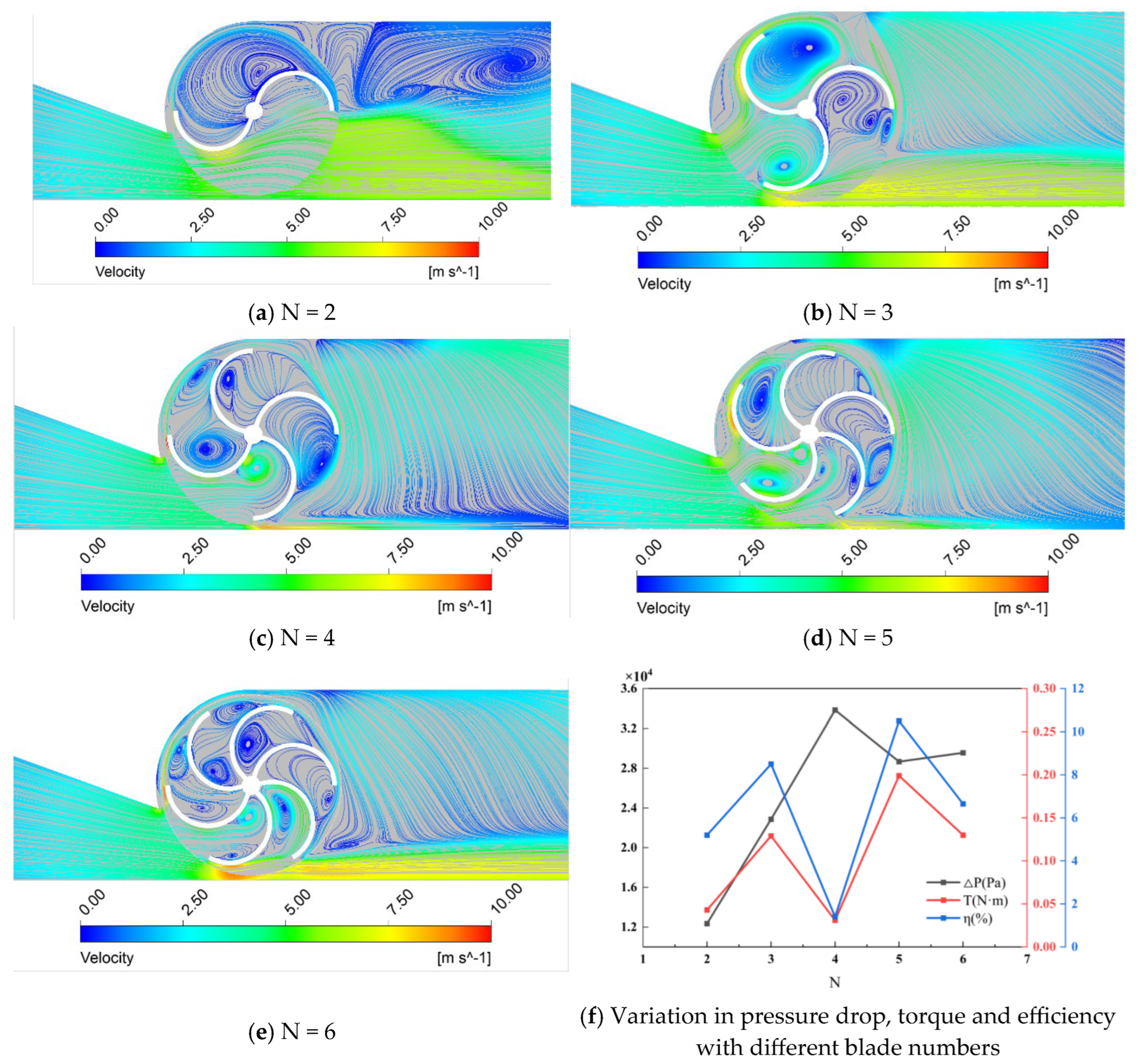
To reveal the reasons for the differences in pressure drop, output torque, and efficiency of the Savonius turbine under varying blade counts, a further analysis of the flow field was conducted. Figure 8a–e present the streamline plots at the central cross-section of the Savonius turbine for different blade counts. Figure 8f further illustrates the variations in turbine pressure drop, torque, and efficiency with varying blade counts. It reveals that with a two-bladed rotor, the channel distance between adjacent blades is excessively large. This results in the formation of vortices in the effective flow that impinge on the blades, within the channels between adjacent blades, making it difficult for the fluid to exit. In the downstream region of the turbine, the distribution of streamlines becomes chaotic, and larger vortices and secondary backflows are formed. These phenomena lead to unstable operation of the Savonius turbine and reduce its overall efficiency. As the number of blades increases, the channel spacing decreases, the contact area between the fluid and the blades increases, and the amount of fluid leakage decreases. At this point, the water flow impacts the blades, causing them to perform work, which increases the output torque and efficiency. However, the pressure loss also increases simultaneously. It should be emphasized that a four-bladed rotor exhibits varying degrees of vortices in each blade channel, and the three channels all show confined flow phenomena, resulting in the lowest efficiency. In summary, compared with the cases of other blade numbers, the efficiency of the five-blade rotor is the highest, reaching about 11%.

3.2. Optimization of Structure Parameters

3.2.1. Database Establishment

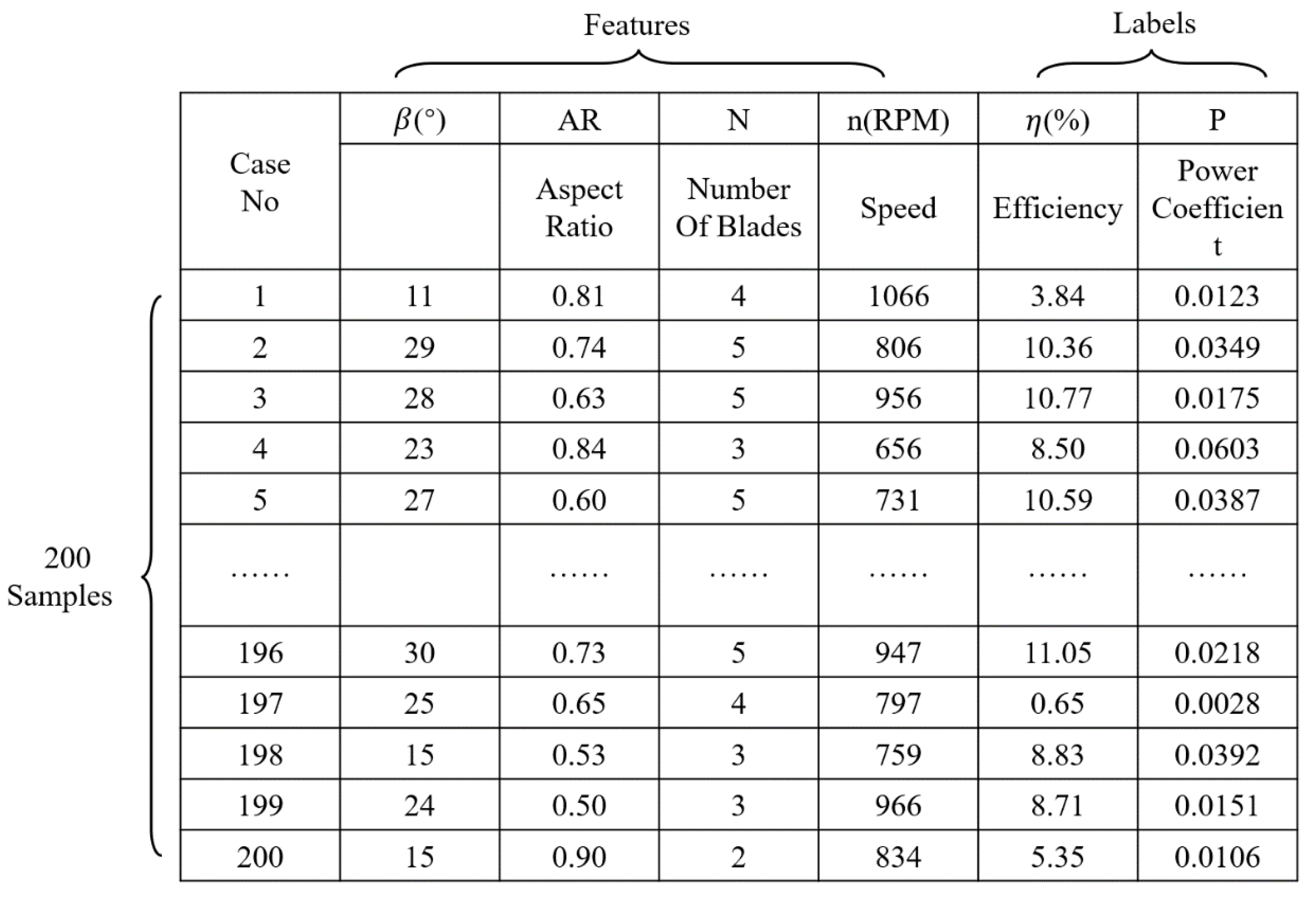
A broad learning system approach was employed to conduct a multi-factor coupling analysis of deflector angle, aspect ratio, number of blades, and rotational speed. This analysis was designed to generate optimized structural data for the hydrokinetic turbine. A Sobol sequence generator was used to produce a uniformly distributed dataset in the multidimensional space. Each sample in the dataset was then subjected to numerical simulation to evaluate the turbine’s efficiency and power coefficient. The value ranges for the three parameters are shown in Table 3. A portion of the generated dataset and its corresponding numerical simulation results are presented in Figure 9.

3.2.2. Model Training and Evaluation

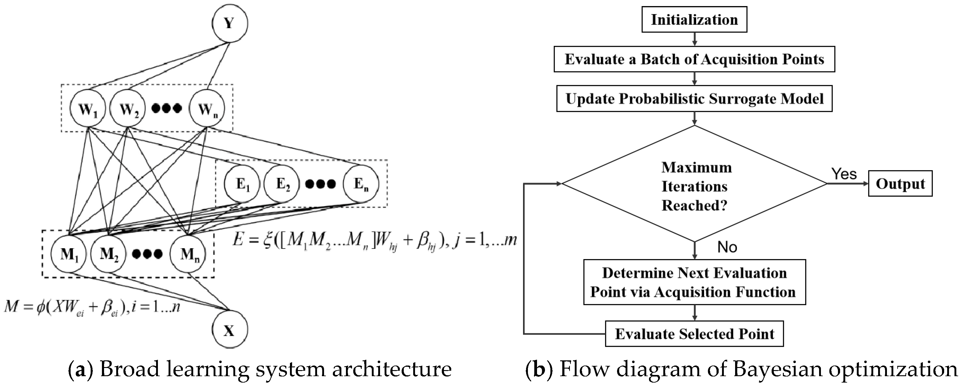
Python 3.11.0 is applied to develop a Bayesian-optimized broad learning model. The broad learning system architecture and flow diagram of Bayesian optimization are shown in Figure 10. The deflector angle, AR, number of blades, rotational speed, efficiency, and power coefficient data for the Savonius turbine were imported into the machine learning model. The data were partitioned into training and testing sets (80% training, 20% testing) and then subjected to Bayesian optimization.
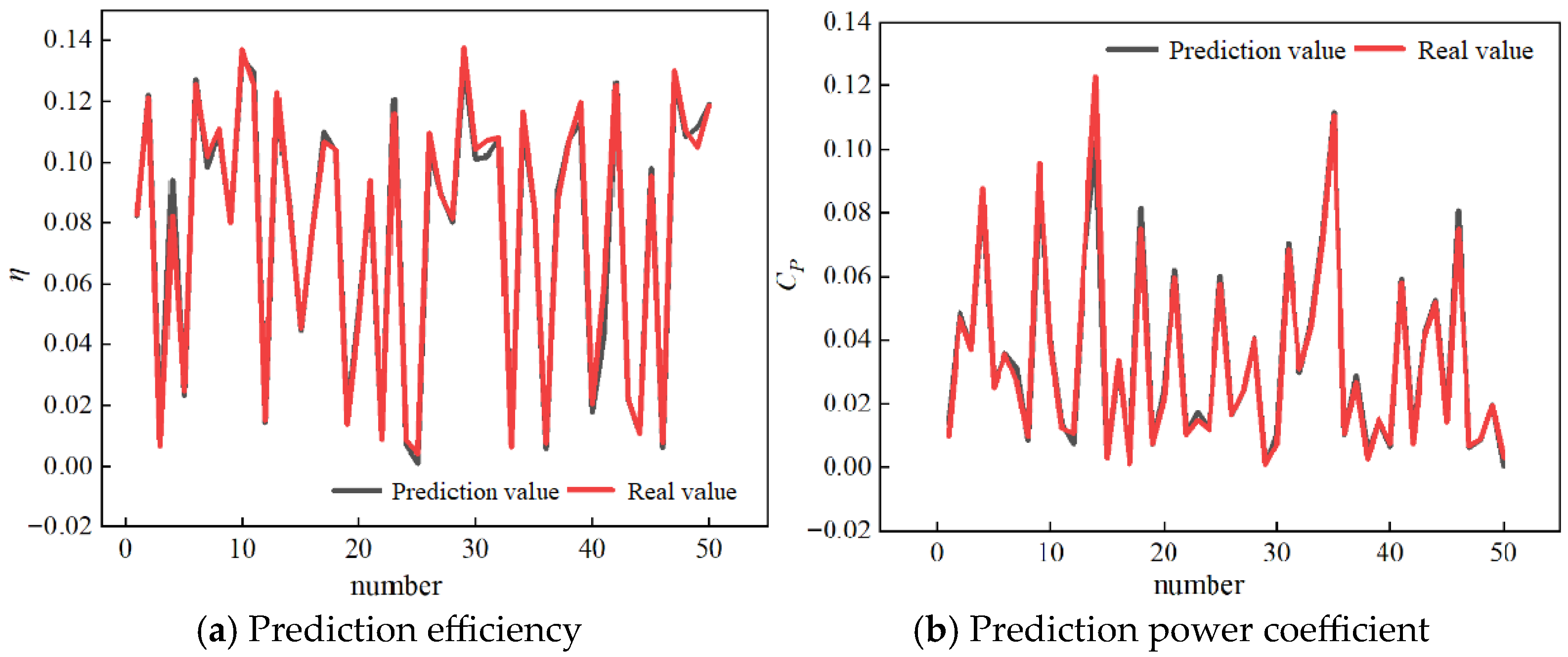
The broad learning system was iterated 200 times, resulting in the following optimized hyperparameters: 157 mapping nodes, 476 enhancement nodes, a linear mapping function, a hyperbolic tangent enhancement function, and a regularization parameter of 0.00024. The prediction results for turbine efficiency and power coefficient using the Bayesian-optimized broad learning system are shown in Figure 11. The close correspondence between the predicted and actual values suggests that the proposed prediction model is highly accurate.

3.2.3. Analysis and Validation of Optimization Results

A grid search method was applied to identify the maximum and minimum values for efficiency and power coefficient, and the results are shown in Table 4. For the search aimed at maximizing efficiency, the grid search determined the optimal parameter combination to be a deflector angle of 10°, an aspect ratio of 0.775, a blade count of 3, and a rotational speed of 1098 r/min, resulting in a corresponding efficiency of 0.2073. For the search aimed at maximizing the power coefficient, the grid search identified the optimal parameter combination as a deflector angle of 10°, an AR of 0.9, a blade count of 3, and a rotational speed of 600 r/min, resulting in a maximum power coefficient of 0.1501.
To validate the accuracy of the broad learning system (BLS) model for predicting the structural parameters and performance of the hydrokinetic turbine, numerical simulations were conducted on the optimized turbine structures. The predicted values from the BLS model were then compared with the numerical simulation results, and the results are presented in Table 5. The prediction errors for efficiency and power coefficient using the BLS model were 1.383% and 0.868%, respectively. Given that these errors fall within an acceptable range, it can be concluded that the neural network model is accurate.

4. Conclusions

In this study, the numerical simulation, machine learning, and experimental validation methods are combined to conduct a deeply theoretical analysis and optimization design of Savonius hydro turbines with an internal diameter of 60 mm, resulting in an efficiency higher than that reported in the current literature. Based on a Bayesian-optimized broad learning model, the optimal parameter combination for the maximum efficiency is determined as follows: the deflector angle of 10°, the aspect ratio of 0.775, the blade number of 3, and the rotational speed of 1098 r/min, achieving a maximum efficiency of 21.73%. The optimal parameter combination for the maximum power coefficient is a deflector angle of 10°, an aspect ratio of 0.9, blade number of 3, and a rotational speed of 600 r/min. At this time, the maximum power coefficient reaches 0.1859.
Leveraging a broad learning method instead of deep learning offers an advantage in machine learning efficiency without sacrificing accuracy, exhibiting considerable potential for engineering development applications. While the current CFD accuracy is sufficient for demonstrating the effectiveness of the proposed methodology, further improvements are desirable. Consequently, future research will investigate the implementation of higher-order turbulence models, such as LES and DNS, to address the observed discrepancies and potentially enhance the overall optimization performance.

Author Contributions

Conceptualization, J.Z. and W.S.; methodology, J.Z. and Y.X.; software, X.L. and H.Y.; validation, X.L., J.H. and Y.Z.; formal analysis, X.L. and J.H.; investigation, X.L.; resources, J.Z.; data curation, X.L. and H.Y.; writing—original draft preparation, X.L.; writing—review and editing, W.S., Y.X. and J.Z.; visualization, X.L. and J.H.; supervision, J.Z.; project administration, J.Z.; funding acquisition, W.S. and J.Z. All authors have read and agreed to the published version of the manuscript.

Funding

This research was funded by the Natural Science Foundation of Xiamen (3502Z202571044), the Natural Science Foundation of Fujian Province (2025J01873, 2021J01854) and the Scientific Research Foundation of JiMei University (ZQ2020013).

Institutional Review Board Statement

Not applicable.

Informed Consent Statement

Not applicable.

Data Availability Statement

The data presented in this study are available upon request from the corresponding author.

Acknowledgments

The authors gratefully acknowledge AOKE LOT TECHNOLOGY Co., Ltd., Xiamen, China for providing experimental facilities for this research.

Conflicts of Interest

The authors declare no conflicts of interest.

References

  1. Jamil, F.; Ibrahim, M.; Ullah, I.; Kim, S.; Kahng, H.K.; Kim, D.H. Optimal smart contract for autonomous greenhouse environment based on IoT blockchain network in agriculture. Comput. Electron. Agric. 2022, 192, 106573. [Google Scholar] [CrossRef]
  2. Darko, R.O.; Yuan, S.; Hong, L.; Liu, J.; Yan, H. Irrigation, a productive tool for food security—A Review. Acta Agric. Scand. Sect. B—Soil Plant Sci. 2016, 66, 191–206. [Google Scholar] [CrossRef]
  3. Zhang, C.Z.; Yan, H.; Ni, Y.X.; Akhlaq, M.; Zhou, J.N.; Xue, R. Effect of micro-spray on plant growth and chlorophyll fluorescence parameter of tomato under high temperature condition in a greenhouse. Sci. Hortic. 2022, 306, 111441. [Google Scholar] [CrossRef]
  4. Tang, L.Y.; Tang, S.Q.; Tang, Y.; Yan, H.F. Performance experiment and numerical prediction on the optimization design of the micro-sized water turbine for the hose reel irrigator. Int. J. Agric. Biol. Eng. 2018, 11, 108–115. [Google Scholar] [CrossRef]
  5. Penzotti, G.; Lodi Rizzini, D.; Caselli, S. A planning strategy for sprinkler-based variable rate irrigation. Comput. Electron. Agric. 2023, 212, 108126. [Google Scholar] [CrossRef]
  6. Chen, R.; Li, H.; Wang, J.; Guo, X.; Xiang, Y. Evaluating soil water movement and soil water content uniformity under sprinkler irrigation with different soil texture and irrigation uniformity using numerical simulation. J. Hydrol. 2023, 626, 130356. [Google Scholar] [CrossRef]
  7. Lakhiar, I.A.Z.; Wang, C.G.; He, B.; Hao, B.B.; Han, Y.J.; Wang, B.Y.; Bao, R.X.; Syed, T.N.; Chauhdary, J.N.; Rakibuzzaman, M. A review of precision irrigation water-saving technology under changing climate for enhancing water use efficiency, crop yield, and environmental footprints. Agriculture 2024, 14, 1141. [Google Scholar] [CrossRef]
  8. Azevedo, J.A.R.; Santos, F.E.S. Energy harvesting from wind and water for autonomous wireless sensor nodes. IET Circuits Devices Syst. 2012, 6, 413–420. [Google Scholar] [CrossRef]
  9. Mysorewala, M.F.; Cheded, L.; Aliyu, A. Review of energy harvesting techniques in wireless sensor-based pipeline monitoring networks. Renew. Sustain. Energy Rev. 2022, 157, 112012. [Google Scholar] [CrossRef]
  10. Karray, F.; Garcia-Ortiz, A.; Jmal, M.W.; Obeid, A.M.; Abid, M. EARNPIPE: A testbed for smart water pipeline monitoring using wireless sensor network. Procedia Comput. Sci. 2016, 96, 285–294. [Google Scholar] [CrossRef]
  11. Fassahat, A.M.; Qureshi, U.; Tuncay, K. A method to integrate energy harvesters into wireless sensor nodes for embedded in pipe monitoring applications. In Proceedings of the 5th International Conference on Energy Aware Computing Systems & Applications, Cairo, Egypt, 24–26 March 2015. [Google Scholar]
  12. Tian, W.L.; Song, B.W.; Mao, Z.Y. Conceptual design and numerical simulations of a vertical axis water turbine used for underwater mooring platforms. Int. J. Nav. Archit. Ocean. 2013, 5, 625–634. [Google Scholar]
  13. Abdollahzadeh, M.; Zhu, Y.; Bayatsarmadi, B.; Vepsäläinen, M.; Razmjou, A.; Murugappan, K.; Rodopoulos, T.; Asadnia, M. Portable multiplexed ion-selective sensor for long-term and continuous irrigation water quality monitoring. Comput. Electron. Agric. 2024, 227, 109455. [Google Scholar] [CrossRef]
  14. Innocenti, A.; Pazzi, V.; Napoli, M.; Ciampalini, R.; Orlandini, S.; Fanti, R. Electrical resistivity tomography: A reliable tool to monitor the efficiency of different irrigation systems in horticulture field. J. Appl. Geophys. 2024, 230, 105527. [Google Scholar] [CrossRef]
  15. Vandôme, P.; Leauthaud, C.; Moinard, S.; Sainlez, O.; Mekki, I.; Zairi, A.; Belaud, G. Making Technological innovations accessible to agricultural water management: Design of a low-cost wireless sensor network for drip irrigation monitoring in Tunisia. Smart Agric. Technol. 2023, 4, 100227. [Google Scholar] [CrossRef]
  16. Chen, J.; Yang, H.X.; Liu, C.P.; Lau, C.H.; Lo, M. A novel vertical axis water turbine for power generation from water pipelines. Energy 2013, 54, 184–193. [Google Scholar] [CrossRef]
  17. Menet, J.L. A double-step Savonius rotor for local production of electricity: A design study. Renew. Energy 2004, 29, 1843–1862. [Google Scholar] [CrossRef]
  18. Paraschivoiu, I. Wind Turbine Design: With Emphasis on Darrieus Concept; Presses inter Polytechnique: Montréal, QC, Canada, 2002. [Google Scholar]
  19. Khan, M.N.I.; Iqbal, T.; Hinchey, M.; Masek, V. Performance of Savonius rotor as a water current turbine. J. Ocean. Technol. 2009, 4, 71–83. [Google Scholar]
  20. Kumar, A.; Saini, R.P. Performance parameters of Savonius type hydrokinetic turbine: A review. Renew. Sustain. Energy Rev. 2016, 64, 289–310. [Google Scholar] [CrossRef]
  21. Kamoji, M.A.; Kedare, S.B.; Prabhu, S.V. Experimental investigations on single stage, two stage and three stage conventional Savonius rotor. Int. J. Energy Res. 2008, 32, 877–895. [Google Scholar] [CrossRef]
  22. Golecha, K.; Eldho, T.I.; Prabhu, S.V. Influence of the deflector plate on the performance of modified Savonius water turbine. Appl. Energy 2011, 88, 3207–3217. [Google Scholar] [CrossRef]
  23. Rehman, M.U.; Ali, Z. Performance improvement of Savonius hydrokinetic turbine using upstream crescent shape deflector. Multiscale Multidiscip. Model. Exp. Des. 2025, 8, 3. [Google Scholar] [CrossRef]
  24. Payambarpour, S.A.; Najafi, A.F.; Magagnato, F. Investigation of deflector geometry and turbine aspect ratio effect on 3D modified in-pipe hydro Savonius turbine: Parametric study. Renew. Energy 2020, 148, 44–59. [Google Scholar] [CrossRef]
  25. Lv, K.; Xie, Y.; Zhang, X.; Wang, Y. Development of Savonius rotors integrated into control valves for energy harvesting. Sustainability 2020, 12, 8579. [Google Scholar] [CrossRef]
  26. Thiyagaraj, J.; Rahamathullah, I.; Anbuchezhiyan, G.; Barathiraja, R.; Ponshanmugakumar, A. Influence of blade numbers, overlap ratio and modified blades on performance characteristics of the Savonius hydro-kinetic turbine. Mater. Today Proc. 2021, 46, 4047–4053. [Google Scholar] [CrossRef]
  27. Talukdar, P.K.; Sardar, A.; Kulkarni, V.; Saha, U.K. Parametric analysis of model Savonius hydrokinetic turbines through experimental and computational investigations. Energy Convers. Manag. 2018, 158, 36–49. [Google Scholar] [CrossRef]
  28. Sobczak, K. Numerical investigations of an influence of the aspect ratio on the Savonius rotor performance. J. Phys. Conf. Ser. 2018, 1101, 012034. [Google Scholar] [CrossRef]
  29. Saad, A.S.; El-Sharkawy, I.I.; Ookawara, S.; Ahmed, M. Performance enhancement of twisted-bladed Savonius vertical axis wind turbines. Energy Convers. Manag. 2020, 209, 112673. [Google Scholar] [CrossRef]
  30. Payambarpour, S.A.; Najafi, A.F.; Magagnato, F. Investigation of blade number effect on hydraulic performance of in-pipe hydro Savonius turbine. Int. J. Rotating Mach. 2019, 2019, 8394191. [Google Scholar] [CrossRef]
  31. Ma, T.; Yang, H.; Guo, X.; Lou, C.; Shen, Z.; Chen, J.; Du, J. Development of inline hydroelectric generation system from municipal water pipelines. Energy 2018, 144, 535–548. [Google Scholar] [CrossRef]
  32. Abdelaziz, K.R.; Nawar, M.A.; Ramadan, A.; Attai, Y.A.; Mohamed, M.H. Performance assessment of a modified of Savonius rotor: Impact of sine and conical blade profiles. Energy 2023, 272, 127172. [Google Scholar] [CrossRef]
  33. Salleh, M.B.; Kamaruddin, N.M. Power Performance and flow structure analysis of a deflector-augmented Savonius hydrokinetic turbine under variable flow speeds. Ocean. Eng. 2025, 325, 120789. [Google Scholar] [CrossRef]
  34. Ismail, M.A.; Othman, A.K.; Zen, H. Numerical investigation of rotational speed on pump as turbine for microhydro applications. Appl. Mech. Mater. 2016, 833, 11–18. [Google Scholar] [CrossRef]
  35. Hasanzadeh, N.; Payambarpour, S.A.; Najafi, A.F.; Magagnato, F. Investigation of in-pipe drag-based turbine for distributed hydropower harvesting: Modeling and optimization. J. Clean. Prod. 2021, 298, 126710. [Google Scholar] [CrossRef]
  36. Zuo, K.; Ye, Z.; Bu, S.; Yuan, X.; Zhang, W. Fast simulation of airfoil flow field via deep neural network. Aerosp. Sci. Technol. 2024, 150, 109207. [Google Scholar] [CrossRef]
  37. Huang, Z.; Li, T.; Huang, K.; Ke, H.; Lin, M.; Wang, Q. Predictions of flow and temperature fields in a T-Junction based on dynamic mode decomposition and deep learning. Energy 2022, 261, 125228. [Google Scholar] [CrossRef]
  38. Xu, M.; Fan, B.; Lin, R.; Lin, R.; Wu, X.; Zheng, S.; Gu, Y.; Mou, J. Advances in the application of intelligent algorithms to the optimization and control of hydrodynamic noise: Improve energy efficiency and system optimization. Appl. Sci. 2025, 15, 2084. [Google Scholar] [CrossRef]
  39. Li, Q.; Wan, R.; Wu, Z.; Yan, Y.; Zhang, X. Intelligent analysis of flow field in cleaning chamber for combine harvester based on YOLOv8 and reasoning mechanism. Appl. Sci. 2025, 15, 2200. [Google Scholar] [CrossRef]
  40. Gong, L.; Chen, Y. Machine learning-enhanced IoT and wireless sensor networks for predictive analysis and maintenance in wind turbine systems. Int. J. Intell. Netw. 2024, 5, 133–144. [Google Scholar]
  41. Jin, J.; Liu, Z.; Chen, C.L.P. Discriminative graph regularized broad learning system for image recognition. Sci. China Inform. Sci. 2018, 61, 112209. [Google Scholar] [CrossRef]
Figure 1. Geometric structure diagram of the deflector and rotor.
Applsci 15 09181 g001
Figure 2. Diagram of the computational domain.
Applsci 15 09181 g002
Figure 3. Meshing of the computational domain.
Applsci 15 09181 g003
Figure 4. Experimental system in the work.
Applsci 15 09181 g004
Figure 5. Validation of the simulation model.
Applsci 15 09181 g005
Figure 6. Effects of diversion angle on the flow field and turbine performance.
Applsci 15 09181 g006
Figure 7. Effects of height–diameter ratio on the pressure and turbine performance.
Applsci 15 09181 g007
Figure 8. Effects of blade number on the pressure and turbine performance.
Applsci 15 09181 g008
Figure 9. Numerical simulation sample range and the corresponding results.
Applsci 15 09181 g009
Figure 10. Flow diagram of the Bayesian-optimized broad learning model.
Applsci 15 09181 g010
Figure 11. Prediction results of the broad learning for hydraulic turbine.
Applsci 15 09181 g011
Table 1. Maximum efficiency of Savonius turbine with various structural optimization.
FactorRef.Value RangeOptimal ValuePipe DiameterWorking
Condition
η/Cp
Leading Component[16]Vertical and
slanted block
Slanted block with eye-shaped opening = 100 mm Water   speed   1.5   m / s ,   P = 50 kPa η = 15.8%
[23]Crescent
shape
30° = 1000   mm Water speed
0.48 m/s
  Increase   of   19.51 %   in   C p m a x
[24]10–4020° = 100 mm P = 20 kPa, n = 50 rad/s η = 16.2%
Aspect
Ratio
[24]0.4–0.90.9 = 100 mm P = 30 kPa, n = 50 rad/s η = 10.3%
[25]0.8–0.90.8 = 100 mmWater speed 2 m/s η = 8.65%
Blade Number[16]3–2412 = 100 mm Water   speed   1.5   m / s ,   P = 50 kPa η = 15.8%
[30]2–105 = 100 mm P = 20 kPa, n = 50 rad/s η = 28.2%
[26]2–620.3 m × 0.3 mWater speed 0.8 m/s C P = 0.105
[31]3, 6, 9, 1212 = 250 mmWater speed 1.5 m/s η = 6.5%
Blade Shape[27]Oval
semicircle
Semicircle2.5 m × 1.5 m Water speed 0.8 m/s   Increase   of   28.6 %   in   C p m a x
[32]Sine
semicircle
cone
Cone\Wind speed 9 m/s   Increase   of   8.6 %   in   C p m a x
* 19.51% higher C p m a x : crescent shape deflector vs. none deflector; ** 28.6% higher C p m a x : semi-circular turbine vs. elliptical turbine; *** 8.6% higher C p m a x : conical profile vs. conventional profile.
Table 2. Structural design parameters of hydraulic turbine.
ParameterSymbolValue
Rotor OD (mm)D154
Pipe ID (mm)D60
Clearance of rotor blade and pipe inner wall (mm)ε3
Rotor height (mm)h27/29.7/32.4/35.1/37.8/
40.5/43.2/45.9/48.6
The angle between the upper and lower end faces of the rotor and the middle section at the center of the rotor (°)θ-
Blade thickness (mm)tb3
Blade diameter at any section of rotor blade axial directiondi-
Deflector lengthL272.4/179.2/132.0/103.0/83.2
Distance of the deflector across the center planeX18
Deflector angle (°)β10/15/20/25/30
Blockage coefficient χ 0.8
Table 3. Parameter range of S-type hydroturbine.
Parameter β (°) ARNN (rpm)
Range of value10–300.5–0.92–5600–1200
Table 4. Optimal parameters obtained by grid search.
Search TargetValueAngle of
Diversion (°)
Aspect
Ratio
Blade NumberRotational Speed (rpm)
η max 0.2138100.77531098
C P max 0.1859100.93600
Table 5. Comparison of prediction and simulation results of optimal efficiency and power coefficient.
Optimum Parameter η p η s η e r r (%) C pp C ps C perr
Angle of Diversion
(°)
Aspect RatioBlade NumberRotational Speed
(rpm)
100.775310980.21380.21681.383///
100.93600///0.18590.18430.868
The subscript ‘p’ denotes the predicted value, ‘s’ denotes the simulated value, and the ‘err’ denotes the error.
Disclaimer/Publisher’s Note: The statements, opinions and data contained in all publications are solely those of the individual author(s) and contributor(s) and not of MDPI and/or the editor(s). MDPI and/or the editor(s) disclaim responsibility for any injury to people or property resulting from any ideas, methods, instructions or products referred to in the content.