

A Comprehensive Review of Plasma Cleaning Processes Used in Semiconductor Packaging


Abstract
Featured Application
Abstract
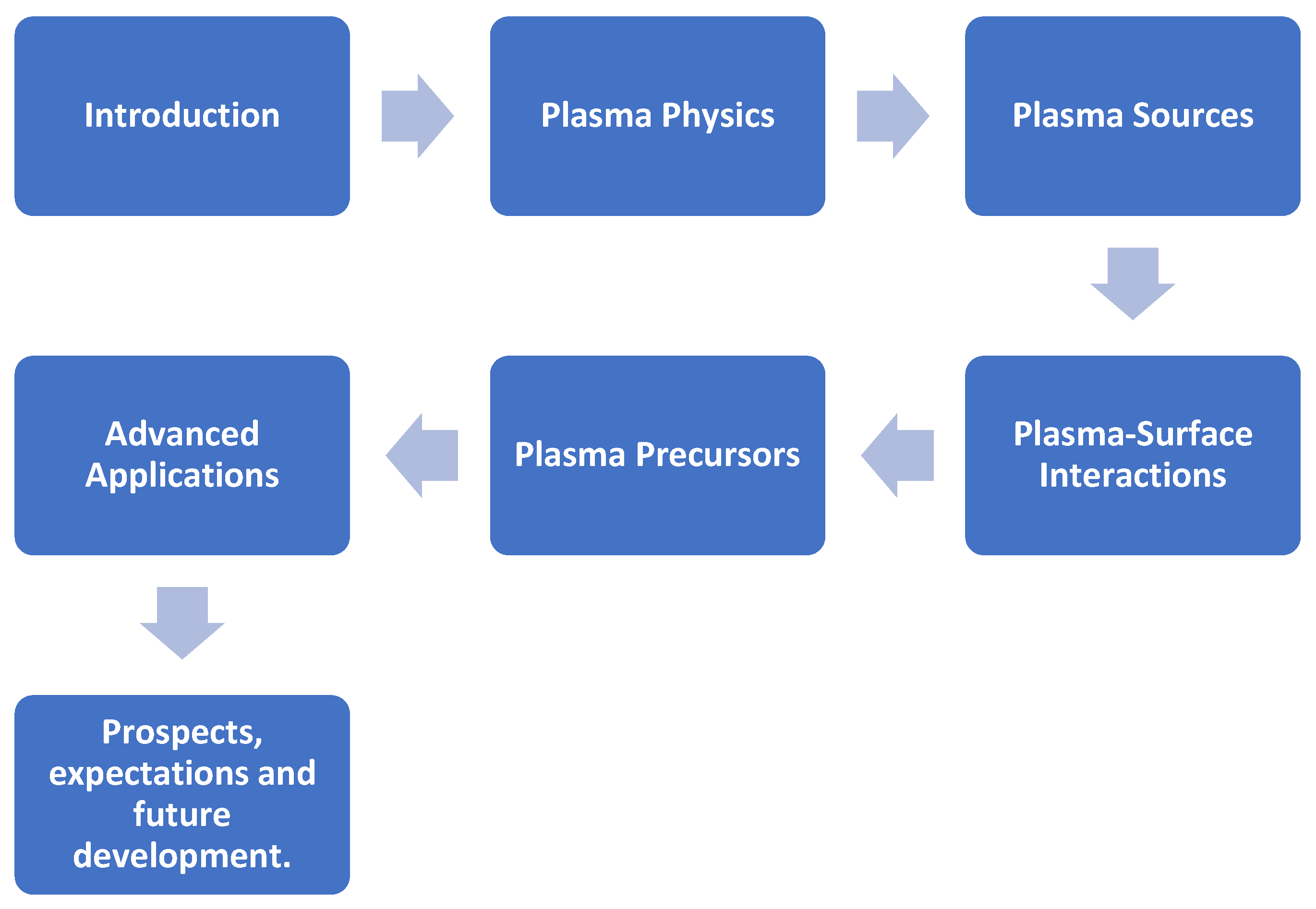
1. Introduction
2. Plasma Physics
2.1. Definition of Plasma
2.2. Bounded Plasmas Which Are Not Thermally Driven
2.3. Pressures Used in Plasma Cleaning Processes
2.4. Plasma Equilibrium
2.5. Ionization
2.6. The Role of Negative Ions in Processing Plasmas
2.7. Collision Cross Section
3. Plasma Sources
3.1. Introduction to the Scoring
Scoring Criteria for Plasma Sources (Based on Table 1 Parameters)
3.2. Direct Current and Pulsed Direct Current Plasma Source
3.3. Radio Frequency Plasma Source
3.4. Microwave (Non-ECR) Plasma Source
- is the maximum electron density;
- f is the source frequency;
- m is the electron mass;
- is the permittivity of free space.
- is the permittivity of free space;
- is the electron mass;
- q is the electron charge;
- is the angular frequency.
3.5. Microwave Using Electron Cyclotron Resonance (ECR) Plasma Source
- is the 2.π.cyclotron frequency [Hz];
- is the mass of an electron;
- e is the electron charge.
3.6. Dielectric Barrier Discharge (DBD) Plasma Source
3.7. Dielectric Coplanar Surface Barrier Discharge (DCSBD)
4. Plasma Interaction with Surfaces
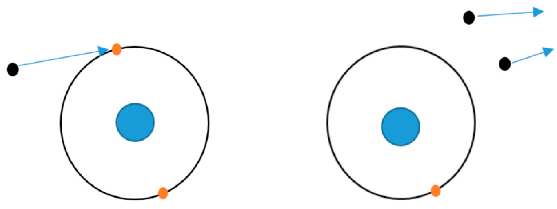
4.1. Physical Bombardment of Surface
4.2. Chemical Reactions with Surfaces
5. Plasma Precursors
5.1. Hydrogen
5.1.1. Elastic and Inelastic Collisions
5.1.2. Vibrational Excitation
- = (v = 1), (v = 2) or (v = 3).
5.1.3. Electronic Excitation
5.1.4. Dissociative Excitation
5.1.5. Ionization
5.1.6. Dissociative Ionization
5.1.7. Recombination
- e represents a free electron;
- represents a positive ion;
- A represents the resulting neutral atom or molecule;
- ħ is the reduced Planck constant;
- ω is the angular frequency of the emitted photon.
5.1.8. Surface Neutralization
- S represents the surface material;
- A+ is the ion species in the plasma;
- is an excited molecule or atom.
5.1.9. Dissociative Attachment
5.1.10. Heavy Particle Interaction
5.1.11. Comparative Analysis
5.2. Oxygen
5.3. Argon
5.4. Helium
5.5. Other Noble Gases
5.6. Nitrogen
5.7. Fluorine and Fluorine Compounds
5.8. Other Halogens—Chlorine and Bromine
5.9. Water
- denotes a high-energy electron.
5.10. Ammonia—NH3
6. Application of Plasma Treatment in Advanced and Emerging Packages
6.1. Flip–Chip Packaging
6.2. Through-Silicon Vias (TSVs)
6.3. Wafer-Level Packaging (WLP)
6.4. 2.5D Interposer-Based Packages
6.5. Hybrid Bonding
6.6. Package on a Package (PoP)
7. Prospects, Expectations, and Future Development
Main Concluding Points
- Trade-off in Plasma Source Selection: The comparative assessment of plasma sources reveals a distinct trade-off between performance and practicality. While electron cyclotron resonance (ECR) microwave systems demonstrate superior potential for efficient chemical processing, this is counterbalanced by their significant operational complexity and cost. In contrast, radio frequency (RF) systems offer a robust and more practical balance of process control and efficacy, explaining their prevalence in industrial applications.
- Specificity of Process Gas Chemistry: The choice of process gas is dictated by the primary cleaning mechanism required. Oxygen excels at removing organic contaminants through oxidation, whereas hydrogen is highly effective for the chemical reduction of metal oxides. For physical cleaning via sputtering, inert argon remains the industry workhorse due to its efficiency and chemical neutrality.
- Limitations of Specialized Chemistries: More complex chemistries present significant compromises. Nitrogen and ammonia, while offering passivation effects, exhibit lower cleaning efficacy and can negatively impact subsequent bonding processes. Halogen-based plasmas, despite their high reactivity, are generally unsuitable for lead frame applications due to their aggressive etching of silicon and metals, and severe toxicity.
- The Principle of Application-Specific Optimization: A central conclusion is that an optimal plasma cleaning strategy is not universal, but is highly contingent upon the specific application. The selection of the source, gas chemistry, and operating parameters must be holistically determined by factors including the contaminants, substrate materials, required final surface condition, and constraints of subsequent process steps.
- Future Development and Research Trajectories: Prospects for future development lie in the optimization of mixed-gas plasmas to leverage synergistic benefits and enhance cleaning efficiency. Further experimental work is warranted to fully characterize the performance, and long-term reliability impacts of emerging chemistries, such as ammonia (NH3), on diverse and advanced packaging architectures.
Funding
Acknowledgments
Conflicts of Interest
Abbreviations
| DC | Direct Current |
| RF | Radio Frequency |
| MW | Microwave |
| ECR | Electron Cyclotron Resonance |
| DBD | Dielectric Barrier Discharge |
| CCP | Capacitively Coupled Plasma |
| ICP | Inductively Coupled Plasma |
| TSV | Through-Silicon Via |
| WLP | Wafer-Level Package |
| FI-WLP | Fan-In Wafer-Level Packaging |
| PoP | Package on Package |
| MSL | Moisture Sensitivity Level |
| UBM | Under-Bump Metallization |
| QFP | Quad Flat Package |
| SOP | Small Outline Package |
| PPF | Pre-Plated Frame |
| AFM | Atomic Force Microscopy |
| XPS | X-ray Photoelectron Spectroscopy |
| TEM | Transmission Electron Microscopy |
| DCSBD | Dielectric Coplanar Surface Barrier Discharge |
References
- Amri, M.; Norhisyam, A.R.W.; Harun, F.; Kadmin, A.F.; Basar, M.F. An improvement of plasma cleaning time towards Leadframe Oxidation Performance. In Proceedings of the Pacific Rim Meeting on Electrochemical and Solid State Science, Bandung, Indonesia, 25–27 November 2019. [Google Scholar] [CrossRef]
- Pulutan, M.L.; Fernandez, M.; Estolano, J. The Effect of Mixed Gas Ar+H2 Strip Plasma onto the Non-Roughened and Oxidation-Roughened Bare Cu Leadframe Surfaces. In Proceedings of the 24th Electronics Packaging Technology Conference (EPTC), Singapore, 7–9 December 2022. [Google Scholar] [CrossRef]
- Abarro, G.J.E.; Santos, R.J.D.; Lazo, D.J.D.; Denoyo, A.B.; Ramos, M.S. Batch Microwave Plasma Cleaning for Robustification of Automotive Devices. An Alternative to Strip-type Radiofrequency Plasma. In Proceedings of the 38th International Electronics Manufacturing Technology Conference 2018, Melaka, Malaysia, 4–6 September 2018. [Google Scholar] [CrossRef]
- Fernandez, M.; Pulutan, M.L.; Arano, A. The Effect of Strip Argon Plasma Cleaning onto the PPF and Ag-plated Cu Leadframe Surfaces. In Proceedings of the 2nd Electronics Packaging Technology Conference EPTC, Singapore, 2–4 December 2020. [Google Scholar] [CrossRef]
- Gibbon, P. Introduction to Plasma Physics. In Proceedings of the CAS-CERN Accelerator School: Plasma Wake Acceleration, Geneva, Switzerland, 23–29 November 2014. [Google Scholar] [CrossRef]
- Hughes, M.A. Investigation of Surface Treatment by H2O Plasma; Portland State University: Portland, ON, USA, 2019. [Google Scholar] [CrossRef]
- Chabert, P.; Braithwaite, N. Physics of Radio Frequency Plasmas; Cambridge University Press: Cambridge, UK, 2011. [Google Scholar]
- Flamm, D.L. Plasma Chemistry, Basic Processes and PECVD. In Plasma Processing of Semiconductors; Springer: Berlin/Heidelberg, Germany, 1997; pp. 23–59. [Google Scholar]
- Scientific, P. Plasma, the Fourth State of Matter. PIE Scientific LLC 2022, 2022. [Online]. Available online: https://piescientific.com/resource_pages/resource_introduction_to_plasma/ (accessed on 24 July 2024).
- Xiao, H. Plasma Basic. Available online: https://km2000.us/mywritings/ICTechnology-Hongxiao.pdf (accessed on 4 August 2024).
- Sabat, K.C. Physics and Chemistry of Solid State Direct Reduction of Iron Ore by Hydrogen Plasma. Phys. Chem. Solid State 2021, 22, 292–300. [Google Scholar] [CrossRef]
- Harry, J.E. Introduction to Plasma Technology; Wiley-VCH: Rutland, UK, 2010. [Google Scholar] [CrossRef]
- Chen, F.F. Introduction to Plasma Physics and Controlled Fusion; Springer: Los Angles, CA, USA, 2015. [Google Scholar] [CrossRef]
- Lieberman, M.A.; Lichtenberg, A.J. Principles of Plasma Discharges and Materials Processing; John Wiley & Sons, Inc.: Hoboken, NJ, USA, 2005; Volume 30, pp. 899–901. [Google Scholar] [CrossRef]
- Keidar, M.; Beilis, I.I. Plasma Engineering; Elsevier: London, UK, 2018. [Google Scholar]
- Laporta, V.; Celiberto, R.; Tennyson, J. Dissociative electron attachment and electron-impact resonant dissociation of vibrationally excited O2 molecules. Phys. Rev. 2015, 91, 012701. [Google Scholar] [CrossRef]
- Wadehra, J.; Bardsly, J. Vibrational- and rotational-state dependence of dissociative attachment in e-H2 collisions. Phys. Rev. Lett. 1978, 41, 1795–1798. [Google Scholar] [CrossRef]
- Fridman, A.; Kennedy, L.A. Plasma Physics and Engineering; CRC Press: New York, NY, USA, 2011. [Google Scholar] [CrossRef]
- Fridman, A. Plasma Chemistry; Cambridge University Press: Cambridge, UK, 2008. [Google Scholar] [CrossRef]
- Bogaerts, A.; Neyts, E.; Gijbels, R.; Van der Mullen, J. Gas discharge plasmas and their applications. Acta Part B At. Spectrosc. 2002, 57, 609–658. [Google Scholar] [CrossRef]
- Freidberg, J.P. Plasma Physics and Fusion Energy; Cambridge University Press: Cambridge, UK, 2007. [Google Scholar] [CrossRef]
- Shafranov, V.D. Plasma equilibrium in a magnetic field. Rev. Plasma Phys. 1996, 2, 103–151. [Google Scholar] [CrossRef]
- Roth, J.R. Industrial Plasma Engineering: Volume 2—Applications to Nonthermal Plasma Processing; Institute of Physics Publishing: New York, NY, USA, 2001. [Google Scholar] [CrossRef]
- Conrads, H.; Schmidt, M. Plasma generation and plasma sources. Plasma Sources Sci. Technol. 2000, 9, 441–454. [Google Scholar] [CrossRef]
- Lieberman, M.A.; Lichtenberg, A.J. Particle and Energy Balance in Discharges. In Principles of Plasma Discharges and Materials Processing; John Wiley & Sons: Hoboken, NJ, USA, 2005; pp. 285–326. [Google Scholar] [CrossRef]
- Tiwari, N.; Bhandari, S.; Ghorui, S. Stability and structures in atmospheric pressure DC non-transferred arc plasma jets of argon, nitrogen, and air. Phys. Plasmas 2018, 25, 072103. [Google Scholar] [CrossRef]
- Meichsner, J.; Schmidt, M.; Schneider, R.; Wagner, H.-E. Nonthermal Plasma Chemistry and Physics; CRC Press: Boca Raton, FL, USA, 2013. [Google Scholar] [CrossRef]
- Kogelschatz, U. Dielectric Barrier Discharges: Their History, Discharge Physics, and Industrial Applications. Plasma Chem. Plasma Process. 2003, 23, 1–46. [Google Scholar] [CrossRef]
- Roth, J. Plasma Sources for Materials Processing; Springer: Berlin/Heidelberg, Germany, 1995. [Google Scholar]
- Gibbon, P. Introduction to Plasma Physics. In The Proceedings of the CAS-CERN Accelerator School; CERN: Genève, Switzerland, 2014. [Google Scholar]
- PVATepla. Microwave Plasma System GIGA 690; PVA Metrology & Plasma Solutions GmbH: Wettenberg, Germany, 2021. [Google Scholar]
- Semicon, V. Plasma Cleaner. [Online]. Available online: http://www.visionsemicon.co.kr/en/product/?tpf=product/view_vision&category_code=1011&code=89 (accessed on 23 March 2025).
- Kawamura, E.; Vahedi, V.; Lieberman, M.A.; Birdsall, C.K. Ion energy distributions in rf sheaths; review, analysis and simulation. Plasma Sources Sci. Technol. 1999, 8, R45–R64. [Google Scholar] [CrossRef]
- Bastami, A.A. Dynamic Matching System for Radio-Frequency Plasma Generation. In Proceedings of the IEEE ENergy COnversation Congress and Expositions, Milwaukee, WI, USA, 18–22 September 2016. [Google Scholar] [CrossRef]
- Carter, D.; Brouk, V. Detecting and Preventing Instabilities in Plasma Processes. In Proceedings of the 52nd Annual Technical Conference Proceedings, Santa Clara, CA, USA, 9–14 May 2009. [Google Scholar]
- Bardos, L.; Barankova, H. Microwave Plasma Sources and Methods in Processing Technology; John Wiley & Sons: Hoboken, NJ, USA, 2024. [Google Scholar] [CrossRef]
- Cohen, W.; Gilgenbach, R.; Jaynes, R.; Peters, C.; Lopez, M.; Lau, Y.-Y. Radio-frequency plasma cleaning for mitigation of high-power microwave-pulse shortening in a coaxial gyrotron. Appl. Phys. Lett. 2000, 77, 3725–3727. [Google Scholar] [CrossRef]
- Hupert, J.J. Evanescent fields in physics and their interpretations in terms of flowgraphs. Appl. Phys. A 1975, 6, 131–149. [Google Scholar] [CrossRef]
- Bosisio, R.G.; Wetheimer, M.R.; Weissfloch, C.F. Generation of large volume microwave plasmas. J. Phys. E Sci. Instrum. 1973, 6, 628–630. [Google Scholar] [CrossRef]
- Belkind, A.; Greshman, S. Plasma Cleaning of Surfaces. Vac. Technol. Coat. 2008, 46. [Google Scholar]
- Paschen, F. Ueber die zum Funkenübergang in Luft, Wasserstoff und Kohlensäure bei verschiedenen Drucken erforderliche Potentialdifferenz. Ann. Phys. 1889, 273, 69–96. [Google Scholar] [CrossRef]
- Chen, F.F. Introduction to Plasma Physics; Plenum Press: New York, NY, USA, 1974. [Google Scholar]
- Chen, F. Chapter 1—Helicon plasma sources. In High Density Plasma Sources; Noyes Publications: Park Ridge, NJ, USA, 1995; pp. 1–75. [Google Scholar] [CrossRef]
- Mallick, C.; Bandyopadhyay, M.; Kumar, R. Interplay among various cavity modes in a microwave plasma system with well-defined cavity geometry. Phys. Plasmas 2025, 32, 012104. [Google Scholar] [CrossRef]
- Inan, U.S.; Golkowski, M. Principles of Plasma Physics for Engineers and Scientists; Cambridge University Press: Cambridge, MA, USA, 2011. [Google Scholar] [CrossRef]
- Rossnagel, S.; Cuomo, J.; Westwood, W. Handbook of Plasma Processing Technology; Asmussen, J., Ed.; Noyes Publications: Park Ridge, NJ, USA, 1990; p. 305, Chapter 11. [Google Scholar]
- Lebedev, Y. Microwave discharges at low pressures and peculiarities of the processes in strongly non-uniform plasma. Plasma Sources Sci. Technol. 2015, 24, 39. [Google Scholar] [CrossRef]
- McTaggart, F. Plasma Chemistry in Electrical Discharges; Elsevier: Amsterdam, The Netherlands, 1967. [Google Scholar]
- Polak, L.; Lebedev, Y.A. Plasma Chemistry; Cambridge International Science Publishing: London, UK, 1998; ISBN 13:9781898326229. [Google Scholar]
- Achkasov, K.; Latrasse, L.; Jacomino, J.-M. Plasma Generation Using Solid-State Microwave Technology. Ampere Newsl. 2016, 89, 22–26. [Google Scholar]
- Samukawa, S. Wave propagation and plasma uniformity in an electron cyclotron resonance plasma. J. Vac. Sci. Technol. A 1993, 11, 2572–2576. [Google Scholar] [CrossRef]
- Asmussen, J. Electron cyclotron resonance microwave discharges for etching and thin-film deposition. J. Vac. Sci. Technol. A 1989, 7, 883–893. [Google Scholar] [CrossRef]
- Popov, O.A. High Density Plasma Sources: Design, Physics, and Performance; Noyes Publications: Littleton, CO, USA, 1994; ISBN 978-0-8155-1377-3. [Google Scholar]
- Makabe, T.; Petrovic, Z.L. Plasma Electronics: Applications in Microelectronic Device Fabrication; Taylor & Francis: Boca Raton, FL, USA, 2006. [Google Scholar] [CrossRef]
- Thierry. How Does Dielectric Barrier Discharge Help Manufacturers? [Online]. Available online: https://www.thierry-corp.com/plasma-treatment-articles/how-does-dielectric-barrier-discharge-help-manufacturers (accessed on 21 March 2025).
- Barjasteh, A.; Lamichhane, P.; Dehghani, Z.; Kaushik, N.; Gupta, R.; Choi, E.H.; Kaushik, N.K. Recent Progress of Non thermal Atmospheric Pressure Plasma for Seed Germination and Plant Development: Current Scenario and Future Landscape. J. Plant Growth Regul. 2023, 42, 5417–5432. [Google Scholar] [CrossRef]
- Brandenburg, R. Dielectric barrier discharges: Progress on plasma sources and on the understanding of regimes and single filaments. Plasma Sources Sci. Technol. 2017, 26, 053001. [Google Scholar] [CrossRef]
- Lu, X.; Laroussi, M.; Li, W. Dielectric Barrier Discharges: Progress on Plasma Sources and Applications; Springer: Berlin/Heidelberg, Germany, 2020. [Google Scholar]
- Gibalov, V.I.; Pietsch, G.J. The development of dielectric barrier discharges in gas gaps and on surfaces. J. Phys. D Appl. Phys. 2000, 33, 2618–2636. [Google Scholar] [CrossRef]
- Golubovskii, Y.B.; Maiorov, V.A.; Behnke, J.; Behnke, J.F. Modelling of the homogeneous barrier discharge in helium at atmospheric pressure. J. Phys. D Appl. Phys. 2002, 36, 39–49. [Google Scholar] [CrossRef]
- Jovanović, A.P.; Stankov, M.N.; Loffhagen, D.; Becker, M.M. Fluid Modelling of Dielectric Barrier Discharges for Plasma Technology. In Comsol Conference; Springer: Berlin/Heidelberg, Germany, 2020. [Google Scholar]
- Subedi, D.P.; Joshi, U.M.; Wong, C.S. Dielectric Barrier Discharge (DBD) Plasmas and Their Applications; Springer: Berlin/Heidelberg, Germany, 2017. [Google Scholar] [CrossRef]
- Pamreddy, A.; Skácelová, D.; Haničinec, M. Plasma cleaning and activation of silicon surface in Dielectric Coplanar Surface Barrier Discharge. Surf. Coatings Technol. 2013, 236, 326–331. [Google Scholar] [CrossRef]
- Čech, J.; Hanusová, J.; Sťahel, P.; Černák, M. Diffuse Coplanar Surface Barrier Discharge in Artificial Air: Statistical Behaviour of Microdischarges. Open Chem. 2014, 13, 000010151520150062. [Google Scholar] [CrossRef]
- Skácelová, V.D.D.; Schäfer, J.; Quade, A.; Sťahel, P. Room temperature plasma oxidation in DCSBD: A new method for preparation of silicon dioxide films at atmospheric pressure. Mater. Sci. Eng. B 2013, 178, 651–655. [Google Scholar] [CrossRef]
- Tučeková, Z.; Kučerová, K.; Zahoranová, A.; Černák, M. Parameters of Plasma Generated by Diffuse Coplanar Surface Barrier Discharge Used for Inactivation of Escherichia Coli. Eur. Phys. J. Appl. Phys. 2016, 75, 2. [Google Scholar] [CrossRef]
- Becker, K.; Kogelschatz, U.; Schoenbach, K.; Barker, R. Non-Equilibrium Air Plasmas at Atmospheric Pressure; CRC Press: Boca Raton, FL, USA, 2004. [Google Scholar] [CrossRef]
- Tendero, C.; Tixier, C.; Tristant, P.; Desmaison, J.; Leprince, P. Atmospheric pressure plasmas: A review. Spectrochim. Acta Part B At. Spectrosc. 2006, 61, 2–30. [Google Scholar] [CrossRef]
- Thanu, D.P.; Srinadhu, E.S.; DOle, N.V.; Keswani, M. Fundamentals and Applications of Plasma Cleaning. Dev. Surf. Contam. Clean. 2019, 11, 289–353. [Google Scholar] [CrossRef]
- Plasma, S.C. SCIPlasma Plasma and Vacuum Specialists. [Online]. Available online: https://www.sciplasma.com/ (accessed on 18 July 2024).
- Giraldo-Mejía, H.; Quintero, Y.M.; Mery, F.; Rodriguez, F.; Curcio, E.; Estay, H.; Garcia, A. Plasma-grafting surface modifications to enhance membrane hydrophobicity for brine membrane distillation. Desalination 2023, 567, 116942. [Google Scholar] [CrossRef]
- Oehr, C. Plasma surface modification of polymers for biomedical use. Nucl. Instrum. Methods Phys. Res. Sect. B Beam Interact. Mater. At. 2003, 208, 40–47. [Google Scholar] [CrossRef]
- Liston, E.M.; Martinu, L.; Wertheimer, M.R. Plasma surface modification of polymers for improved adhesion: A critical review. J. Adhes. Sci. Technol. 1993, 7, 1091–1127. [Google Scholar] [CrossRef]
- Carone, E.; Graef, W.; Hagelaar, G. Data Needs for Modeling Low-Temperature Non-Equilibrium Plasmas: The LXCat Project. Hist. Perspect. A Tutorial. At. 2021, 9, 16. [Google Scholar]
- Fuchs, P. Low-pressure plasma cleaning of Au and PtIr noble metal surfaces. Appl. Surf. Sci. 2009, 256, 1382–1390. [Google Scholar] [CrossRef]
- Korner, N.; Beck, E.; Dommann, A.; Onda, N.; Ramm, J. Hydrogen Plasma Chemical Cleaning of Metallic Substrates and Silicon Wafers. Surf. Coatings Technol. 1995, 76–77, 731–737. [Google Scholar] [CrossRef]
- Baklanov, M.R.; Shamiryan, D.G.; Tökei, Z.; Beyer, G.P.; Conrad, T.; Vanhaelemeersch, S. Characterization of Cu surface cleaning by hydrogen plasma. J. Vac. Sci. Technol. B Microelectron. Nanometer Struct. 2001, 19, 1201–1211. [Google Scholar] [CrossRef]
- Nicolussi, G.; Beck, E. Plasma chemical cleaning of chip carrier in a downstream hollow cathode discharge. In Proceedings of the 13th Annual IEEE/SEMI Advanced Semiconductor Manufacturing Conference. Advancing the Science and Technology of Semiconductor Manufacturing, Boston, MA, USA, 30 April–2 May 2002. [Google Scholar] [CrossRef]
- Hassouni, K.; Silva, F.; Gicquel, A. Modelling of Diamond Deposition Microwave Cavity Generated Plasmas. J. Phys. D Appl. Phys. 1999, 43, 15. [Google Scholar] [CrossRef]
- Marques, L.; Jolly, J.; Alves, L. Capacitively Coupled Radio-Frequency Hydrogen Discharges: The Role of Kinetics. J. Appl. Phys. 2007, 102, 063305. [Google Scholar] [CrossRef]
- IST-Lisbon Database. [Online]. Available online: www.lxcat.net (accessed on 10 November 2024).
- Capitelli, M.; Ferreira, C.; Gordiets, B.; Osipov, A. Plasma Kinetics in Atmospheric Gases; Springer: Berlin/Heidelberg, Germany, 2000. [Google Scholar] [CrossRef]
- Janev, R.K.; Langer, W.D.; Post, D.E.; Evans, K. Elementary Processes in Hydrogen-Helium Plasmas; Springer: Berlin/Heidelberg, Germany, 1987. [Google Scholar] [CrossRef]
- Carrasco, E.; Tanarro, I.; Herrero, V.J.; Cenicharo, J. Proton transfer chain in cold plasmas of H2 with small amounts of N2. The prevalence of NH4+. Phys. Chem. Chem. Phys. 2013, 15, 1699–1706. [Google Scholar] [CrossRef]
- Samuell, C.M.; Corr, C.S. Atomic and molecular hydrogen gas temperatures in a low-pressure helicon plasma. Plasma Sources Sci. Technol. 2015, 24, 045003. [Google Scholar] [CrossRef]
- Zorat, R.; Vender, D. Global model for an rf hydrogen inductive plasma discharge in the deuterium negative ion source experiment including negative ions. J. Phys. D Appl. Phys. 2000, 33, 1728–1735. [Google Scholar] [CrossRef]
- Skoro, N.; Pua, N.; Lazovi, S.; Cvelbar, U.; Kokkoris, G.; Gogolides, E. Characterization and global modelling of low-pressure hydrogen-based RF plasmas suitable for surface cleaning processes. J. Phys. D Appl. Phys. 2013, 46, 475206. [Google Scholar] [CrossRef]
- Zammit, M.C.; Savage, J.S.; Fursa, D.V.; Bray, I. Electron impact excitation of molecular hydrogen. Phys. Rev. A 2017, 95, 022708. [Google Scholar] [CrossRef]
- Buckman, S.J.; Phelps, A.V. Vibrational excitation of D2 by low energy electrons. J. Chem. Phys. 1985, 82, 4999–5011. [Google Scholar] [CrossRef]
- Corrigan, S.J.B. Dissociation of Molecular Hydrogen by Electron Impact. J. Chem. Phys. 1965, 43, 4381–4386. [Google Scholar] [CrossRef]
- Scarlett, L.H.; Tapley, J.K.; Fursa, D.V.; Zammit, M.C.; Savage, J.S.; Bray, I. Low-energy electron-impact dissociative excitation of molecular hydrogen and its isotopologues. Phys. Rev. A 2017, 96, 062708. [Google Scholar] [CrossRef]
- Hill, C.; Dubernet, M.; Endres, C.; Karwasz, G.; Marinlvic, B.; Marquart, T.; Heinola, K.; Zwolf, C.M.; Moreau, N. Classification of Processes in Plasma Physics. In “Classification of Processes” [1] Produced as an Outcome of the Technical Meeting on Standards and Software Tools for Atomic and Molecular Databases; IAEA Headquarters in Vienna: Wien, Austria, 2024. [Google Scholar]
- Friedrich, J.F.; Meichsner, J. Nonthermal Plasmas for Materials Processing; Scrivener Publishing LLC: Beverly, MA, USA, 2022. [Google Scholar] [CrossRef]
- Franz, G. Low Pressure Plasmas and Miscrostructuring Technology; Springer: Munchen, Germany, 2009; ISBN 9783549858485. [Google Scholar]
- Suhr, H. Organic Syntheses under plasma Conditions. In Proceedings of the International Symposium on Plasma Chemistry, Kiel, Germany, 6–10 September 1973. [Google Scholar] [CrossRef]
- Mendez, I.; Gordillo-Vazquez, F.J.; Herrero, V.; Tanarro, I. Atom and Ion Chemistry in Low Pressure Hydrogen DC Plasmas. J. Phys. Chem. A 2006, 110, 6060–6066. [Google Scholar] [CrossRef]
- Bogaerts, A.; Gijbels, R. Effects of adding hydrogen to an argon glow discharge: Overview of relevant processes and some qualitative explanations. J. Anal. At. Spectrom. 2000, 15, 441–449. [Google Scholar] [CrossRef]
- Nishi, M.; Yamada, M.; Suckewer, S.; Rosengaus, E. Measurements of Sputtering Yields for Low-Energy Plasma Ions; Princeton Plasma Physics Lab. (PPPL): Princeton, NJ, USA, 1979. [Google Scholar] [CrossRef]
- Onda, N.; Stössel, Z.; Dommann, A. DC-Hydrogen Plasma Cleaning A Novel Process for IC-Packaging. In Proceedings of the Semicon West Packaging Materials Conference, San Diego, CA, USA, 16 July 1997. [Google Scholar]
- Johnson, N.; Doland, C.; Ponce, F.; Walker, J.; Anderson, G. Hydrogen in crystalline semiconductors: A review of experimental results. Phys. B Condens. Matter 1991, 170, 3–20. [Google Scholar] [CrossRef]
- Pearton, S.J.; Corbett, J.W.; Shi, T.S. Hydrogen in crystalline semiconductors. Appl. Phys. A 1987, 43, 153–195. [Google Scholar] [CrossRef]
- Pearton, S.J.; Corbett, J.W.; Stavola, M. Hydrogen in Crystalline Semiconductors; Springer: Berlin/Heidelberg, Germany, 1992. [Google Scholar] [CrossRef]
- Lee, S.H.; Iza, F.; Lee, J.K. Particle in cell Monte Carlo and fluid simulations of argon-oxygen plasma: Comparisons with experiments and validations. Phys. Plasmas 2006, 13, 057102. [Google Scholar] [CrossRef]
- Noakes, T.; Valizadeh, R.; Hannah, A.; Jones, L.; Militsyn, B. Oxygen plasma cleaning of copper for photocathode applications: A MEIS and XPS study. Vacuum 2022, 205, 111424. [Google Scholar] [CrossRef]
- Coburn, J.W.; Winters, H.F. Plasma etching—A discussion of mechanisms. Crit. Rev. Solid State Mater. Sci. 1981, 10, 119–141. [Google Scholar] [CrossRef]
- Winters, H.F.; Coburn, J. Surface science aspects of etching reactions. Surf. Sci. Rep. 1992, 14, 162–269. [Google Scholar] [CrossRef]
- Chytrosz-Wrobel, P.; Golda-Cepa, M.; Stodoak-zych, E. Effect of oxygen plasma-treatment on surface functional groups, wettability, and nanotopography features of medically relevant polymers with various crystallinities. Appl. Surf. Sci. Adv. 2023, 18, 100497. [Google Scholar] [CrossRef]
- Hsieh, J.; Fong, L.H.; Yi, S.; Metha, G. Plasma cleaning of copper leadframe with Ar and Ar/H2 gases. Surf. Coatings Technol. 1999, 112, 245–249. [Google Scholar] [CrossRef]
- Schmidtt, R.; Hoder, W.; Tilgner, R. RBS Measurement of The Thickness of Nanometer Oxide Layers: Adhesion Strength Between Copper Leadframe and Molding Compound Correlated with The Oxide Layer Thickness. In Proceedings of the IEEVCPMT Electronic Packaging Technology Conference, Singapore, 10 October 1997. [Google Scholar] [CrossRef]
- Kanarik, K.J.; Lill, T.; Hudson, E.A.; Sriraman, S.; Tan, S.; Marks, J.; Vahedi, V.; Gottscho, R.A. Overview of atomic layer etching in the semiconductor industry. J. Vac. Sci. Technol. A 2015, 33, 020802. [Google Scholar] [CrossRef]
- Pulutan, M.L.; Fernandez, M.; Estolano, J.; Philippines, A. Surface Plasma and Mold Deflash Treatment of Plated and Non-Plated Cu Leadframe for Leadframe-to-Mold Adhesion Improvement. In Proceedings of the 2021 IEEE 23rd Electronics Packaging Technology Conference, Singapore, 7–9 December 2021. [Google Scholar] [CrossRef]
- Chao, S.-C.; Huang, W.-C.; Liu, J.-H.; Song, J.-M. Oxidation characteristics of commercial copper-based lead frame surface and the bonding with epoxy molding compounds. Microelectron. Reliab. 2019, 99, 161–167. [Google Scholar] [CrossRef]
- ELectronic, D. Plasma Surface Technology. Diener. [Online]. Available online: https://www.plasma.com/en/plasma-technology-glossary/noble-gas/ (accessed on 9 January 2025).
- Eckstein, W. Sputtering Yields. In Sputtering by Particle Bombardment; Springer: Berlin/Heidelberg, Germany, 2007; pp. 33–187. [Google Scholar] [CrossRef]
- Chu, P.K.; Lu, X. Low Temperature Plasma Technology; CRC Press: New York, NY, USA, 2014. [Google Scholar] [CrossRef]
- Shibanov, D.; Lopaev, D.; Maslakov, K.; Konnikova, M.; Rakhimov, A. SiO2 sputtering by low-energy Ar+, Kr+, and Xe+ ions in plasma conditions. Vacuum 2024, 231, 113767. [Google Scholar] [CrossRef]
- Jeon, H.J.; Hong, S.J. Ammonia Plasma Surface Treatment for Enhanced Cu–Cu Bonding Reliability for Advanced Packaging Interconnection. Coatings 2024, 14, 1449. [Google Scholar] [CrossRef]
- Sun, T.-H.; Liu, Y.-L.; Li, C.-T.; Tsai, W.-T.; Hsu, M.-P.; Chen, K.-N. Low-Temperature Adhesive Hybrid Bonding Technology with Novel Area-Selective Passivation Layer. In Proceedings of the International 3D Systems Integration Conference (3DIC), Sendai, Japan, 25–27 September 2024. [Google Scholar]
- Cardinaud, C. Fluorine- based plasmas: Main features and application in micro and nanotechnology and in surface treatment. Comptes Rendus Chim. 2018, 21, 723–739. [Google Scholar] [CrossRef]
- MKS. Astron Remote Plasma Source—Atomic Fluorine Transport; MKS Instruments, Inc.: Andover, MA, USA, 2022; Available online: https://www.mks.com/mam/celum/celum_assets/resources/ASTRONAtomicFluorineTransport-AppNote.pdf?1 (accessed on 1 April 2025).
- Strobel, M.; Lyons, C.; Mittal, K. Plasma Surface Modification of Polymerts: Relevance to Adhesion; Taylor and Francis Group: New York, NY, USA, 1994. [Google Scholar]
- Coburn, J.W.; Winters, H.F. Ion- and electron-assisted gas-surface chemistry—An important effect in plasma etching. J. Appl. Phys. 1979, 50, 3189–3196. [Google Scholar] [CrossRef]
- Flamm, D.L.; Donnelly, V.M.; Mucha, J.A. The Reaction of Fluorine Atoms with Silicon. J. Appl. Phys. 1981, 52, 3633–3639. [Google Scholar] [CrossRef]
- Das, P.P. Chapter 13—Fluorine: Risk assessment, environmental, and health hazard. In Hazardous Gases—Risk Assessment on the Environment and Human Health; Academic Press: Cambridge, MA, USA, 2021; pp. 153–167. [Google Scholar] [CrossRef]
- Progress, P.I. H2O-Based Plasma Cleaning. Advanced Plasma Treatment Technology for Metal Surface “Cleaning + Reduction”. [Online]. Available online: https://www.samcointl.com/opto/featured-solutions/plasma-cleaning-metal-copper-silver/ (accessed on 19 July 2024).
- Wang, T.; Jia, H.; Guo, X.; Xia, T.; Qu, G.; Sun, Q.; Yin, X. Evaluation of the potential of dimethyl phthalate degradation in aqueous using sodium percarbonate activated by discharge plasma. Chem. Eng. J. 2018, 346, 65–76. [Google Scholar] [CrossRef]
- Joshi, A.A.; Locke, B.R.; Arce, P.; Finney, W.C. Formation of hydroxyl radicals, hydrogen peroxide and aqueous electrons by pulsed streamer corona discharge in aqueous solution. J. Hazard. Mater. 1995, 41, 3–30. [Google Scholar] [CrossRef]
- Ni, G.; Lan, Y.; Cheng, C.; Meng, Y.; Wang, X. Reforming of methane and carbon dioxide by DC water plasma at atmospheric pressure. Int. J. Hydrogen Energy 2011, 36, 12869–12876. [Google Scholar] [CrossRef]
- Fangyuan, L.; Deping, Y.; Cheng, L.; Yazhou, D.; Zhong, Y. Experimental study on the jet characteristics of a steam plasma torch. Plasma Sci. Technol. 2018, 20, 125401. [Google Scholar] [CrossRef]
- SAMCO. Aqua Plasma Boost® and AQ-2000BT: Excellent for Reducing Large Sized Samples of Oxidized Copper; SAMCO: Kyoto, Japan, 2023; Available online: https://www.samcointl.com/news-events/tech-reports/aqua-plasma-boost-and-aq-2000bt-excellent-for-reducing-large-sized-samples-of-oxidized-copper/#:~:text=Samco%27s%20Aqua%20Plasma%20Boost%C2%AE%20enhances%20oxidized%20copper%20reduction%2C,surface%20hydro (accessed on 6 April 2025).
- Krenek, P. Thermophysical Properties of H2O-Ar Plasmas at Temperatures 400–500,000 K and Pressure 0.1 MPa. Plasma Chem. Plasma Process. 2007, 28, 107–122. [Google Scholar] [CrossRef]
- Andersen, J.; Veer, K.V.; Christensen, J.; Østberg, M.; Bogaerts, A. Ammonia decomposition in a dielectric barrier discharge plasma: Insights from experiments and kinetic modeling. Chem. Eng. Sci. 2023, 271, 118550. [Google Scholar] [CrossRef]
- Chang, Y.-M.; Leu, J.; Lin, B.-H.; Wang, Y.-L.; Cheng, Y.-L. Comparison of H2 and NH3 Treatments for Copper Interconnects. Adv. Mater. Sci. Eng. 2013, 2013, 825195. [Google Scholar] [CrossRef]
- Ito, F.; Shobha, H.; Tagami, M.; Nogami, T.; Cohen, S.; Ostrovski, Y.; Molis, S.; Maloney, K.; Femiak, J.; Protzman, J.; et al. Effective Cu Surface Pre-Treatment for High-Reliable 22 Nm-Node Cu Dual Damascene Interconnects with High Plasma Resistant Ultra Low-k Dielectric (K = 2.2). Microelectron. Eng. 2012, 92, 62–66. [Google Scholar] [CrossRef]
- Yu, A.; Hu, R.; Liu, W.; Zhang, R.; Zhang, J.; Pu, Y.; Chu, L.; Yang, J.; Li, X. Preparation and Characterization of Mn Doped Copper Nitride Films with High Photocurrent Response. Curr. Appl. Phys. 2018, 18, 1306–1312. [Google Scholar] [CrossRef]
- Wu, C.-K.; Yin, M.; O’Brien, S.; Koberstein, J.T. Quantitative Analysis of Copper Oxide Nanoparticle Composition and Structure by X-Ray Photoelectron Spectroscopy. Chem. Mater. 2006, 18, 6054–6058. [Google Scholar] [CrossRef]
- Wang, D.Y.; Nakamine, N.; Hayashi, Y. Properties of Various Sputter-Deposited Cu–N Thin Films. J. Vac. Sci. Technol. A 1998, 16, 2084–2092. [Google Scholar] [CrossRef]
- National Library of Medicine. National Center for Biotechnology Information, [Online]. Available online: https://www.ncbi.nlm.nih.gov/books/NBK598714/ (accessed on 6 April 2025).
- Dong, B.; Driver, M.S.; Emesh, I.; Shaviv, R.; Kelber, J.A. Surface chemistry and fundamental limitations on the plasma cleaning of metals. Appl. Surf. Sci. 2016, 384, 294–297. [Google Scholar] [CrossRef]
- Godard, M.; Drouin, D.; Darnon, M.; Martel, S.; Fortin, C. Plasma Treatment for Fluxless Flip-Chip Chip-Joining Process. In Proceedings of the IEEE 68th Electronic Components and Technology Conference (ECTC), San Diego, CA, USA, 29 May–1 June 2018. [Google Scholar] [CrossRef]
- Davoine, C.; Fendler, M.; Marion, C.L.F.; Fortunier, R. Low temperature fluxless flip chip technology for fine pitch bonding. In Proceedings of the 56th Electronic Components and Technology Conference 2006, San Diego, CA, USA, 30 May–2 June 2006. [Google Scholar] [CrossRef]
- Xiong, Z.P.; Sze, H.P.; Chua, K.H. Bump non-wet issue in large-die flip chip package with eutectic Sn/Pb solder bump and SOP substrate pad. In Proceedings of the Proceedings of 6th Electronics Packaging Technology Conference (EPTC 2004) (IEEE Cat. No.04EX971), Singapore, 8–10 December 2004. [Google Scholar] [CrossRef]
- Wakeel, S.; Meng, D.K.P.; Chin, S.W.W.; Philipsen, J.; Joosten, P.G.A.A. Effect of plasma and staging time on the underfill voids in fine pitch flip-chip package. In Proceedings of the 22nd International Conference on Electronic Packaging Technology (ICEPT), Xiamen, China, 14–17 September 2021. [Google Scholar] [CrossRef]
- Teo, M.; Lee, K.Y.; Chew, A.; Lim, S. Plasma Surface Modification and Impact on MSL Performance for Flip Chip Packaging. In Proceedings of the 9th Electronics Packaging Technology Conference, Singapore, 10–12 December 2007. [Google Scholar]
- Park, J.-C.; Lee, T.-K. Surface Activation Beneath the Flip Chip by Plasma Treatments. IEEE Trans. Components, Packag. Manuf. Technol. 2022, 12, 1712–1718. [Google Scholar] [CrossRef]
- Kim, Y.S.; Kodama, S.; Mizushima, Y.; Araki, N.; Hsiao, C.; Chang, H. Optimization of Via Bottom Cleaning for Bumpless Interconnects and Wafer-on-Wafer (WOW) Integration. In Proceedings of the IEEE 68th Electronic Components and Technology Conference (ECTC), San Diego, CA, USA, 29 May–1 June 2018. [Google Scholar] [CrossRef]
- Lim, S.P.-S.; Ding, M.Z.; Kawano, M. Chip-to-Wafer (C2W) flip chip bonding for 2.5D high density interconnection on TSV free interposer. In Proceedings of the IEEE 19th Electronics Packaging Technology Conference (EPTC), Singapore, 6–9 December 2017; pp. 1–7. [Google Scholar] [CrossRef]
- Butler, D.; Jones, C.; Burgess, S.; Wilby, T.; Densley, P. Fan-Out Wafer Processing In The High Density Packaging Era. In Proceedings of the International Wafer Level Packaging Conference (IWLPC), San Jose, CA, USA, 23–25 October 2018. [Google Scholar] [CrossRef]
- Rao, V.S. Development of High Density Fan Out Wafer Level Package (HD FOWLP) with Multi-layer Fine Pitch RDL for Mobile Applications. In Proceedings of the IEEE 66th Electronic Components and Technology Conference (ECTC), Las Vegas, NV, USA, 31 May–3 June 2016; pp. 1522–1529. [Google Scholar] [CrossRef]
- Zhao, J. Plasma Applications for Wafer Level Packaging Part 1. In Proceedings of the 20th International Conference on Electronic Packaging Technology(ICEPT), Hong Kong, China, 12–15 August 2019. [Google Scholar] [CrossRef]
- Yang, Y. Effects of Plasma Treatment on Adhesion and Flow Behavior of Underfill in 2.5D Electric Package. In Proceedings of the 24th International Conference on Electronic Packaging Technology (ICEPT), Shihezi City, China, 8–11 August 2023. [Google Scholar] [CrossRef]
- Park, S.; Lee, S.; Kim, S.E. Two-Step Ar/N2 Plasma Treatment on SiO2 Surface for Cu/SiO2 Hybrid Bonding. IEEE Trans. Compon. Packag. Manuf. Technol. 2024, 14, 723–728. [Google Scholar] [CrossRef]
- Sun, X.; Pan, M.; Lu, Y.; Wan, L. A novel package-on-package stacking technique. In Proceedings of the 14th International Conference on Electronic Packaging Technology, Dalian, China, 11–14 August 2013. [Google Scholar] [CrossRef]
- Co, R.; Katkar, R.; Prabhu, A.S.; Zohni, W. High-Volume-Manufacturing (HVM) of BVA enabled advanced Package-on-Package (PoP). In Proceedings of the International Conference on Electronics Packaging and iMAPS All Asia Conference (ICEP-IAAC), Kyoto, Japan, 4–6 May 2015. [Google Scholar]
- Kim, D.K.; Park, Y.K.; Biswas, S.; Lee, C. Removal efficiency of organic contaminants on Si wafer surfaces by the N2O ECR plasma technique. Mater. Chem. Phys. 2005, 91, 490–493. [Google Scholar] [CrossRef]


| Parameter | Description |
|---|---|
| Energy Distribution and Plasma Uniformity | The energy distribution in a plasma refers to how energy is spread across the particles within the plasma. This includes the distribution of kinetic energy among electrons, ions, and neutral particles and effects the overall behaviour and characteristics of the plasma, such as its temperature and reaction rates. Plasma uniformity, on the other hand, refers to the consistency of plasma properties (like density, temperature, and composition) across the entire volume of the plasma. Uniformity is crucial for processes like plasma etching, where consistent results are needed across a surface [14,19,20]. |
| Plasma Stability | Plasma stability is a parameter which is critical to evaluate plasma and outlines how the ability of the plasma to maintain its equilibrium state without developing instabilities, fluctuations, or disruptions [13,20,21,22]. |
| Plasma Energy Density | Plasma density refers to the number of charged particles (electrons and ions) per unit volume in a plasma. It is typically measured in particles per cubic centimetre (cm3). Plasma density is a crucial parameter because it influences the plasma’s electrical properties, chemical reactivity, and overall behaviour [13,14,19]. |
| Electron Temperature | In non-thermal plasmas, the electron temperature is much higher than the gas temperature, often reaching thousands of Kelvin (or several eV), while the gas remains near room temperature. This high electron temperature enables the generation of reactive species, such as ions and radicals, without overheating the material being treated. This unique property allows for effective surface cleaning of heat-sensitive materials like semiconductors These energetic electrons create ions and radicals through electron-impact dissociation, excitation, and ionization of background gas molecules, which then participate in surface reactions to remove contaminants or modify surface properties. The selective energy transfer to electrons (rather than heavy particles) ensures that the process remains non-destructive to temperature-sensitive substrates, making non-thermal plasmas indispensable for precision applications in microelectronics and advanced material processing [14,20,23,24]. |
| Parameter | Scores | Score Explanation |
|---|---|---|
| Energy Distribution and Plasma Uniformity | High Scores (8–10) | Awarded to sources consistently reported to produce highly uniform plasma across large areas/volumes with well-controlled energy distribution functions, crucial for consistent semiconductor processing. Evidence includes studies demonstrating low spatial variation in plasma density, temperature, or cleaning rates. |
| Moderate Scores (4–7) | Sources that can achieve good uniformity, but may require specific configurations, careful tuning, or are inherently prone to some non-uniformities (e.g., edge effects or filamentation under certain conditions). | |
| Low Scores (0–3) | Sources known for significant non-uniformities, localized power deposition, or difficulty in achieving consistent treatment across the semiconductor products without advanced engineering solutions. | |
| Plasma Stability | High Scores (8–10) | Sources known for stable operation over wide parameter ranges, minimal arcing, low fluctuation in plasma parameters, and robust performance against changes in process conditions (e.g., outgassing). |
| Moderate Scores (4–7) | Sources that are generally stable but may exhibit instabilities under certain conditions (e.g., specific pressure/power regimes, impedance matching challenges) or require sophisticated control systems. | |
| Low Scores (0–3) | Sources inherently prone to instabilities, arcing, mode-hopping, or significant fluctuations that can impact process reproducibility. | |
| Plasma Energy Density (Focus on Achievable Ion/Radical Density Necessary for Processing) | High Scores (8–10) | Sources capable of generating high-density plasmas (e.g., >1011–1012 cm−3 ions/radicals) efficiently, leading to faster cleaning rates. |
| Moderate Scores (4–7) | Sources that produce moderate plasma densities, suitable for cleaning but potentially slower or less intense than high-density sources. | |
| Low Scores (0–3) | Sources typically characterized by lower plasma densities, which may limit processing speed or the intensity of plasma–surface interactions. | |
| Electron Temperature (Effective Range for Generating Reactive Species) | High Scores (8–10) | Sources that typically operate with electron temperatures (e.g., 2–10 eV) highly effective for generating the desired reactive species (radicals, ions) through electron impact dissociation and ionization of process gases, without excessive ion energies that could cause damage. |
| Moderate Scores (4–7) | Sources achieving electron temperatures that are effective but might be in a range less optimal for certain gas chemistries or require more power to achieve desired radical densities. | |
| Low Scores (0–3) | Sources where electron temperatures are typically too low for the efficient generation of key reactive species for common cleaning gases, or conversely, too high, leading to undesirable ionization states or excessive heating/damage if not well-controlled. |
| Parameter | References | Parametric Score |
|---|---|---|
| Energy Distribution and Plasma Uniformity | When compared with other plasma sources, such as radiofrequency (RF) or microwave plasmas, direct current (DC) plasmas typically exhibit less uniform energy distribution and lower plasma uniformity. DC plasmas rely on a continuous electric field, which can lead to localized heating and an uneven energy distribution. By pulsing the DC power, the plasma operates in short, controlled bursts, which reduces localized heating and allows for better management of energy distribution across the plasma volume. However, pulsed DC plasmas still generally fall short of the uniformity achieved by RF or microwave plasmas, which benefit from higher-frequency oscillations and more efficient energy coupling [14,19,24]. |  4/10 |
| Plasma Stability | DC plasmas are generally less stable compared with other plasma systems, such as MW plasmas. This is especially true when the system is working at higher power levels. Stability issues arise due to the formation of arcs or thermal instabilities, which can occur when the plasma transitions from a glow discharge to an arc discharge. It is also important to note that the stability of DC plasmas is highly dependent on the current–voltage characteristics and the gas composition [26]. |  4/10 |
| Plasma Energy Density | Due to the intermittent nature of the discharge and the dielectric barrier, which limits the power that can be delivered to the plasma, DBD systems have lower energy density than other plasma systems, such as RF plasmas [18,27,28,29]. |  6/10 |
| Electron Temperature | DC plasma systems achieve moderate electron temperature levels in the range of 1–5 eV. In higher-powered cleaning systems, this can go up to 10 eV [30]. |  6/10 |
| Parameter | References | Parametric Score |
|---|---|---|
| Energy Distribution and Plasma Uniformity | Sheath dynamics are particularly critical in RF plasma systems as most of the energy is concentrated within this narrow boundary region [33]. The strong electric fields in the sheath accelerate ions toward surfaces, governing essential processes like ion bombardment energy and radical generation. In contrast, the bulk plasma region exhibits relatively uniform energy distribution, with electron temperatures (Te) of 1–5 eV and densities (ne) of 1015–1017 m−3 under typical processing conditions [34]. |  7/10 |
| Plasma Stability | RF plasmas can experience stability issues due to variations in plasma impedance, especially at low pressures and powers. The interaction between the plasma and the RF power delivery system can lead to instabilities if not properly managed; however, the literature has indicated that advanced power delivery systems having features like variable frequency and real-time impedance measurement can help in detecting and mitigating instabilities to provide stable plasma generation [35]. |  9/10 |
| Plasma Energy Density | RF plasmas have significant sheath regions where most of the energy is concentrated. Therefore, although energy density of RF plasmas is similar to that of MW plasmas, the distribution is not as uniform. Inductively coupled plasmas have higher energy densities than capacitively coupled plasmas [7,31]. |  7/10 |
| Electron Temperature | In RF plasmas, electrons are heated primarily in the sheath regions and through collisions in the bulk plasma. The electron temperature reached by RF plasmas in moderately sized industrial plant can range between 2 and 10 eV. However, in low-pressure RF plasmas, such as those used in cleaning, the range is normally between 1 and 5 eV [14]. |  6/10 |
| Parameter | References | Parametric Score |
|---|---|---|
| Energy Distribution and Plasma Uniformity | Microwave plasmas operate at high frequencies when compared with other plasma systems, such as RF, typically around 2.45 GHz. Microwave plasmas do not have a significant sheath region, with energy being uniformly distributed in the bulk plasma. Non-ECR plasma systems are very reliant on the microwave cavity and field distribution to achieve uniformity [44]. |  7/10 |
| Plasma Stability | The reviewed literature has indicated that microwave plasmas are generally more stable than DC or RF plasmas due to uniform energy distribution; however, this depends a lot on the microwave cavity design and the control circuitry for the microwave system [36]. |  8/10 |
| Plasma Energy Density | Microwave plasmas have no significant sheath regions, and energy is uniformly distributed in the bulk plasma. The literature has indicated that plasma densities reached would reach the order of 1010 cm−3 [36]. |  7/10 |
| Electron Temperature | In microwave plasmas, electrons are heated directly by the microwave field, leading to more efficient ionization than that in many other comparable models. The electron temperature achieved is among the highest, with temperatures ranging between 2 and 8 eV [14]. |  7/10 |
| Parameter | References | Parametric Score |
|---|---|---|
| Energy Distribution and Plasma Uniformity | Microwave ECR systems also operate at 2.45 GHz, but include a static magnetic field to achieve electron cyclotron resonance. This is influenced by the resonance condition, where electrons gain energy efficiently from the microwave field. ECR plasmas typically have a more anisotropic EEDF, with electrons gaining significant transverse energy due to the cyclotron motion. ECR plasmas tend to have better uniformity due to the efficient energy transfer and the resonance condition, which helps to maintain a consistent plasma density. In terms of uniformity, this is also enhanced by the magnetic field configuration, which helps to distribute the plasma more evenly [50,51]. |  8/10 |
| Plasma Stability | ECR plasmas use a magnetic field to confine electrons and achieve resonance with microwave energy. This results in highly stable plasmas with minimal fluctuations. However, this is very reliant on the static magnetic field alignment, and improper alignment or strength of the magnetic field can disrupt resonance and cause instability, hence the slight reduction in scoring. Another important issue is pressure control, as deviations in pressure level can affect stability. ECR systems are also dependent on microwave frequency control, which must closely match the electron cyclotron resonance condition for optimal stability [36,52,53]. |  7/10 |
| Plasma Energy Density | The literature has indicated that the plasma density that can be achieved is very high when compared with that in other plasma systems. The plasma density for ECR plasma systems can be up to 1013 cm−3 [52,53]. |  9/10 |
| Electron Temperature | ECR systems can reach very high electron temperatures ranging between 10 and 20 eV [36]. Some high-power systems can even exceed 30 eV up to 50 eV; however, these are not lead frame cleaning systems [14,54]. |  9/10 |
| Parameter | References | Parametric Score |
|---|---|---|
| Energy Distribution and Plasma Uniformity | DBD plasma discharges operate in a filamentary mode, where plasma forms as discrete micro discharges. DBD plasma is generally less uniform than microwave or radiofrequency (RF) plasmas due to its filamentary nature [28,57,58,59]. Electrons in DBD plasmas tend to have a non-Maxwellian energy distribution due to the transient and localized nature of the micro-discharges [60]. |  5/10 |
| Plasma Stability | The plasma from this source generally has lower stability than comparable MW or RF sources. However the stability of DBD plasmas depends also on the ambient setting. At atmospheric pressure, DBD plasmas often operate in a filamentary mode, where the discharge consists of many micro-discharges (filaments). These filaments are spatially and temporally random, but are stabilized by the dielectric barrier. At lower pressures, DBD plasmas can achieve a more homogeneous (glow-like) discharge, although DBD plasmas are not generally used in vacuum conditions, apart from in a few limited applications [55]. |  6/10 |
| Plasma Energy Density | DBD plasmas typically operate at lower energy densities compared with RF plasmas. The energy density in DBD systems is influenced by the dielectric material and the applied voltage, which limits the current and prevents arcing [61]. |  6/10 |
| Electron Temperature | The electron temperature in DBD plasmas typically ranges from 1 to 10 eV [18,27,62]. |  6/10 |
| Parameter | References | Parametric Score |
|---|---|---|
| Energy Distribution and Plasma Uniformity | The literature has indicated that the diffuse coplanar surface barrier discharge (DCSBD) technology is specifically designed to create a visually uniform, diffuse, and large-area thin film of plasma [63]. DCSBD creates a highly uniform plasma that treats the entire surface evenly, preventing the damage associated with non-uniform, filamentary plasmas. The energy distribution within the system is characterized by a highly efficient, non-equilibrium state. This is achieved through the delivery of a substantial density of reactive energy via energetic electrons. This is in deep contrast to DBD plasmas, which have a filamentary energy distribution [64]. |  6/10 |
| Plasma Stability | The DCSBD plasma source exhibits high stability and spatial uniformity, attributed to the formation of a statistically predictable ensemble of micro-discharges. These discharges exhibit a memory effect, whereby discharge channels are preferentially reused, resulting in a time-averaged, macroscopically homogeneous plasma distribution [63,64]. |  7/10 |
| Plasma Energy Density | Previous studies have demonstrated that DCSBD is characterized by a high overall power density, rendering it an attractive candidate for industrial-scale rapid surface processing. This elevated power density has been attributed to the collective statistical behavior of numerous micro-discharges, whose individual energy contributions and spatial distributions can be modulated through adjustments to operating conditions [63,64]. |  7/10 |
| Electron Temperature | Limited literature was found in this area; however, the reviewed text indicated that electron temperature for DCSBD plasmas tend to be lower than DBD plasmas, which in turn is significantly less than that found in vacuum plasmas. In DCSBD plasmas, which operate at atmospheric pressure, electrons collide very frequently with gas molecules, losing energy in these collisions, thus keeping their average energy relatively low. DCBSC plasma systems are generally used for gentle large-area processing [65,66]. |  7/10 |
| Parameter | Scores | Score Explanation |
|---|---|---|
| Removal of Organic Contaminants through Chemical Reduction and Oxidation | High Scores (8–10) | Gases that readily form highly reactive species (e.g., O* and H*) leading to efficient chemical breakdown of common organic residues (oils, polymers, and photo resistant residues) into volatile byproducts, with numerous studies demonstrating high cleaning rates. |
| Moderate Scores (4–7) | Gases that show some effectiveness, but may be slower, less versatile for a broad range of organics, or require more aggressive plasma conditions. | |
| Low Scores (0–3) | Gases that are largely inert toward organic contaminants via chemical pathways or primarily rely on physical removal. | |
| Removal of Oxides Through Chemical Reduction | High Scores (8–10) | Gases (primarily H2 or H2-containing mixtures) whose plasma species (e.g., H*) efficiently reduce common metal oxides (e.g., copper oxides and tin oxides) on lead frames to the base metal, with evidence of successful surface cleaning and restoration of solderability/bondability. |
| Moderate Scores (4–7) | Gases showing limited or slower oxide reduction capabilities or effectiveness only under specific conditions (e.g., elevated substrate temperatures). | |
| Low Scores (0–3) | Gases that do not chemically reduce metal oxides or, in fact, promote oxidation (e.g., O2). | |
| Physical Bombardment Efficacy | High Scores (8–10) | Inert gases whose ions (e.g., Ar+ and Xe+) have appropriate mass and can be accelerated to energies effective for sputtering thin contaminant layers, light oxides, or for surface roughening/activation, without significant chemical alteration. |
| Moderate Scores (4–7) | Gases with some physical cleaning capability, but are less efficient due to lower ion mass, lower ionization efficiency, or competing chemical effects. | |
| Low Scores (0–3) | Gases whose ions are too light for effective bombardment cleaning activity or where chemical reactivity overwhelmingly dominates any physical effect. | |
| Plasma Reliability for Sensitive Devices (Minimizing Damage) | High Scores (8–10) | Gases and associated plasma conditions reported to cause minimal physical or chemical damage to sensitive semiconductor dies or delicate lead frame features (e.g., thin plating and bond pads). This includes low sputtering of substrate, no detrimental chemical etching, and minimal risk of issues like hydrogen embrittlement when properly controlled. |
| Moderate Scores (4–7) | Gases that are generally safe but may pose some risk under non-optimized conditions (e.g., potential for slight oxidation, minor etching, or requiring careful control of ion energy/flux). | |
| Low Scores (0–3) | Gases known to be aggressive toward common semiconductor/lead frame materials (e.g., strong etchants like fluorine, highly oxidizing like pure O2 for certain metals if uncontrolled), posing a significant risk of damage. | |
| Plasma Safety: Handling Precursors and Emissions Risks | High Scores (8–10) | Gases that are inert, non-toxic, non-flammable, and whose plasma processing byproducts are also benign, requiring minimal specialized handling or exhaust abatement. |
| Moderate Scores (4–7) | Gases with some safety considerations (e.g., flammability like H2, oxidizer like O2, or mild precursor toxicity) but manageable with standard industrial safety protocols and potentially requiring simple exhaust treatment. | |
| Low Scores (0–3) | Gases that are highly toxic, corrosive, or pyrophoric as precursors, or produce highly hazardous emissions (e.g., HF from fluorine plasmas and HCN from N2/organic reactions) requiring extensive safety measures and specialized abatement systems. |
| Reaction | Sticking Coefficient (γ) |
|---|---|
| 2H + wall → H2 | 0.03 |
| H+ + wall → H | 0.9 |
| + wall → H2+ H | 0.9 |
| Parameter | Summary | Parametric Score |
|---|---|---|
| Removal of Organic Contaminants Through Chemical Reduction and Oxidation | Hydrogen plasma contains active species, such as atomic hydrogen (H), ions (such as , and ), and electrons. These species react with organic contaminants such as oils and deposits, and break them down into volatile by-products, like , which are then evacuated from the chamber [1]. |  8/10 |
| Removal of Oxides Through Chemical Reduction | Hydrogen plasmas clean and activate lead frame surfaces by reducing copper oxides, which is crucial for improving subsequent processes like wire-bonding or moulding [76]. Studies have shown that, for substrates with a temperature below 150 °C, oxide layers may not be completely reduced. The reduction process appears limited, potentially by the rate of hydrogen diffusion through the oxide or the kinetics of the reaction between hydrogen and the oxide. In contrast, substrates with temperatures higher than 150 °C showed effective oxide reduction by the hydrogen. At low temperatures, increasing processing time removes a larger amount of the oxide layer [77]. |  7/10 |
| Physical Bombardment Efficacy | Hydrogen ions are light, so physical sputtering is less efficient than that with or other heavier ions [98,99]. |  2/10 |
| Plasma Reliability for Sensitive Devices (Minimizing Damage) | Hydrogen has the potential to diffuse into metals and causing embrittlement. However, the literature has shown that hydrogen plasma can be used without damage under controlled conditions with low ion energies, such as those found in semiconductor lead frame cleaning systems. The literature has indicated that hydrogen plasma cleaning systems with ion energies below 10 eV are generally safe for silicon dies if properly optimized. At such low energies, hydrogen ions (, and ) and radicals () primarily perform chemical cleaning (removing organics and oxides) with minimal physical sputtering or lattice damage. However, hydrogen diffusion into sensitive structures (gate oxides and metal interconnects) can still occur if exposure is prolonged or temperatures are high, hence why exposure needs to be limited and temperatures kept low [100,101,102]. |  7/10 |
| Plasma Safety: Handling Precursors and Emissions Risks | H2 is flammable and therefore proper plasma system and process design would be required. However, the by-products emanating from the plasma process are safe molecules, such as , which can be emitted by regular exhaust systems. No specific scrubber systems are required with plasmas that use hydrogen. |  6/10 |
| Parameter | Summary | Parametric Score |
|---|---|---|
| Removal of Organic Contaminants Through Chemical Reduction and Oxidation | Oxygen plasmas generate reactive oxygen species (, and ) that react with organic compounds, such as hydrocarbons, oils, and organic residues. These organic residues are oxidized into volatile by-products, such as , and CO which are easily pumped away [14]. |  8/10 |
| Removal of Oxides Through Chemical Reduction | Oxygen plasmas do not remove oxides; in fact, the opposite is true, as O2 plasma oxidizes Cu, Al, or Ag surfaces, forming CuO on lead frames [104]. |  0/10 |
| Physical Bombardment Efficacy | ) plasmas are poor for physical bombardment compared with inert gases, like argon (Ar) or xenon (Xe), since physical sputtering efficiency depends on momentum transfer from ions to target atoms. Oxygen ions ( and ) are light (16–32 amu) compared with (40 amu) or Xe+ (131 amu), resulting in weak momentum transfer. Oxygen plasmas also have high chemical reactivity, which dominates over physical effects [105]. |  5/10 |
| Potential to Cause Damage to Devices Being Cleaned | Even though lead frame plasma cleaning operates at low energy levels, oxygen radicals react with Cu lead frames to form thin CuO layers. Furthermore, oxygen radicals also react with Al bond pads to form , which has an impact on wire bonding [106,107]. |  4/10 |
| Plasma Safety: Handling Precursors and Emissions Risks | No particular hazards are envisaged with the use of oxygen. Oxygen induces other substances to burn and so some care in the use of oxygen needs to be exercised. |  7/10 |
| Parameter | Summary | Parametric Score |
|---|---|---|
| Removal of Organic Contaminants Through Chemical Reduction and Oxidation | Argon particles do not react chemically with organic contaminants, especially at the low energy levels used in plasma cleaning systems. |  0/10 |
| Removal of Oxides Through Chemical Reduction | Argon particles do not react chemically with metal oxides. |  0/10 |
| Physical Bombardment | Argon plasmas remove organic contaminants and oxides through physical bombardment. However, they are less efficient than oxygen (O2) or hydrogen (H2) plasmas for organic removal because argon lacks chemical reactivity. The literature has indicated that argon plasmas are good for the removal of loosely bound hydrocarbons, light contamination, such as a fingerprints, and surface activation. However, argon plasmas are slow for the removal of thick residues and debris. Carbon residue debris may also remain on the surface, as argon does not produce volatile by-products, such as or produced by oxygen and hydrogen plasmas, respectively [110]. The effective bombardment process created by argon plasma systems also creates an ablative effect on the device surface, thereby effectively removing thin oxide layers. |  8/10 |
| Plasma Reliability for Sensitive Devices (Minimizing Damage) | At the low energies involved in plasma cleaning, no damage to either the silicon die or the lead frames should occur. |  8/10 |
| Plasma Safety: Handling Precursors and Emissions Risks | Ar is a noble gas that is safe to handle. Emissions from the plasma process should be also safe and would not need scrubber systems for disposal. |  9/10 |
| Parameter | Summary | Parametric Score |
|---|---|---|
| Removal of Organic Contaminants Through Chemical Reduction and Oxidation | Helium particles do not react chemically with organic contaminants, especially at the low energy levels used in plasma cleaning systems. |  0/10 |
| Removal of Oxides Through Chemical Reduction | Helium particles do not react chemically with metal oxides. |  0/10 |
| Physical Bombardment | Helium is a non-reactive gas and therefore can be utilized for the creation of plasmas that conduct cleaning through physical bombardment. However, helium particles have a low mass of around 4 amu when compared with 40 amu for argon particles. While helium ions gain similar kinetic energy to heavier ions when accelerated by the plasma sheath, their low mass results in inefficient momentum transfer during collisions with heavier surface atoms. Consequently, helium ions are much less effective at dislodging (sputtering) surface particles compared with ions like argon [14,114]. |  5/10 |
| Plasma Reliability for Sensitive Devices (Minimizing Damage) | Helium plasma processes are not aggressive and are effectively useful for gentle surface activation without material removal. |  10/10 |
| Plasma Safety: Handling Precursors and Emissions Risks | Helium gas is not toxic and not flammable. The fact that helium is a light element precludes it from displacing oxygen in a setup envisaged for the deployment of a plasma system. The handling of helium in the manufacturing environment is therefore not difficult. Emissions from helium plasma processes are similarly not toxic. |  10/10 |
| Parameter | Summary | Parametric Score |
|---|---|---|
| Removal of Organic Contaminants Through Chemical Reduction and Oxidation | Noble gas particles do not react chemically with organic contaminants, especially at the low energy levels used in plasma cleaning systems. |  0/10 |
| Removal of Oxides Through Chemical Reduction | Noble gas particles do not react chemically with metal oxides. |  0/10 |
| Physical Bombardment | All noble gases are non-reactive and good for physical bombardment plasmas. Xe and Kr should be better-suited than argon for kinetic bombardment processes, since their ions are heavier, with (131 amu) > (84 amu) > (40 amu) > (20 amu). Xenon therefore has the best parameters. However, it is important to note that Ne, Kr, and Xe are rare and very costly when compared with Ar. This means that they would only be applicable for specialist applications, such as hard material etching and precision milling. They are not used for general-purpose plasma cleaning. Neon provides less efficient physical sputtering than argon because of its lower atomic mass, which is why argon is favoured for noble gas plasma cleaning. The score is with respect to xenon and krypton [116]. |  9/10 |
| Plasma Reliability for Sensitive Devices (Minimizing Damage) | With adequate control and exposure time, no damage to devices should occur. |  8/10 |
| Plasma Safety: Handling Precursors and Emissions Risks | Noble gases are not hazardous and are safe to handle. Emissions from the plasma process should be also safe and would not need scrubber systems for disposal. This is especially true if the gas volumes are small, as is expected from a non-equilibrium plasma cleaning process. |  8/10 |
| Parameter | Summary | Parametric Score |
|---|---|---|
| Removal of Organic Contaminants Through Chemical Reduction and Oxidation | Nitrogen plasmas react with organic contaminants; however, in general, nitrogen plasmas are weaker in reduction than hydrogen-based plasmas. Nitrogen plasmas also create toxic substances such as cyanates and nitrous oxides when they react with organic contaminants. |  5/10 |
| Removal of Oxides Through Chemical Reduction | Crucially, nitrogen plasma is not an effective reducing agent for typical metal oxides found on lead frames. It does not readily react with CuO or in a way that removes the oxygen and leaves clean metal. Its bond energy (N≡N) is very high, and the resulting radicals do not have the right chemistry to efficiently strip oxygen from metal oxides like hydrogen does. Nitrogen plasmas create nitrides with metals, thereby nitriding surfaces and changing their physical properties. Moreover, as stated before, the volatile oxides of nitrogen are toxic and challenging to handle. On the other hand, the nitride surfaces are effectively passivated, which means that they are protected from future oxidation. The literature has indicated the evaluation of the use of nitrogen as a follow up with other gases, such as hydrogen, to form a passivation layer and also improve the surface roughness created by the precursor hydrogen plasma process [117]. |  4/10 |
| Physical Bombardment | Nitrogen plasmas primarily generate ions such as , which have a lower mass (28 amu) compared with ions (40 amu). Additionally, ion yields in nitrogen plasmas are often lower than those in argon plasmas. These two characteristics—lower ion mass and potentially lower ion density—make nitrogen a less effective gas than argon for plasma processes relying mainly on physical bombardment [14]. |  4/10 |
| Plasma Reliability for Sensitive Devices (Minimizing Damage) | The nitriding process brought about by the nitrogen plasma can have an effect on characteristics of the bond pad surfaces on both the die and the lead frames. This has an impact on wire bonding processes. |  5/10 |
| Plasma Safety: Handling Precursors and Emissions Risks | Nitrogen plasmas can produce highly toxic emissions, such as HCN, CN, and NOx, which requires scrubbing through a special exhaust system. |  2/10 |
| Parameter | Summary | Parametric Score |
|---|---|---|
| Removal of Organic Contaminants Through Chemical Reduction and Oxidation | F* radicals react with hydrocarbons, breaking C-C/C-H bonds and forming volatile by-products; however, some of the products formed are toxic, like hydrogen fluoride, which needs to have a scrubbing system installed. The risk of polymerization is also a major issue. In plasmas like , if there is not enough fluorine relative to carbon, fluorocarbon polymers (-()n-) can deposit on the surface instead of etching. This is the basis of Teflon-like coatings [121]. |  8/10 |
| Removal of Oxides Through Chemical Reduction | Fluorine plasmas are not good at removing oxides from copper or aluminium surfaces as they create fluorides such and , which are not volatile at plasma cleaning temperatures [122]. |  4/10 |
| Physical Bombardment | Fluorine particles are light. At a mass of 19 amu for , the particles are even lighter than nitrogen particles, such as ions, which have a mass of 28 amu. This fact, coupled with the extreme reactivity of fluorine, precludes such plasmas from being used to conduct lead frame cleaning. |  2/10 |
| Plasma Reliability for Sensitive Devices (Minimizing Damage) | Fluorine plasmas destroy Si and and therefore degrade and destroy the die materials. The extreme reactivity of fluorine makes it uncontrollable for lead frame cleaning, as it would destroy most surfaces while the cleaning process is occurring [123]. |  0/10 |
| Plasma Safety: Handling Precursors and Emissions Risks | Fluorine and its radicals are very hazardous to all biological life and require specialized handling [124]. |  0/10 |
| Parameter | Summary | Parametric Score |
|---|---|---|
| Removal of Organic Contaminants Through Chemical Reduction and Oxidation | Chlorine and bromine are also very reactive halogens, although to a lesser extent than fluorine. Therefore, these two substances are not ideal for organic contaminant removal, especially since the literature has not indicated any increase in the speed of the reaction with the use of chlorine and bromine when compared with hydrogen or oxygen. Another negative aspect reviewed in literature is the fact that both halogens attack most metals, forming non-volatile chlorides and toxic by-products such as HCl [14]. |  8/10 |
| Removal of Oxides Through Chemical Reduction | Chlorine and bromine do not remove oxides, as halogens are themselves oxidizing agents. It is also the case that halogens may create non-volatile chlorides and bromides with metals. |  0/10 |
| Physical Bombardment | Chlorine and bromine are not indicated for plasma bombardment mechanisms as they are too reactive and also their particle masses are relatively light when compared with particles of the noble gases argon and xenon. |  3/10 |
| Plasma Reliability for Sensitive Devices (Minimizing Damage) | Chlorine and bromine can both cause extensive damage to die structures and also to the lead frames. |  2/10 |
| Plasma Safety: Handling Precursors and Emissions Risks | Chlorine and bromine are both toxic chemicals that require specific handling regimes. Furthermore, emissions from the plasma processes of both elements are toxic, thus requiring scrubber systems. |  2/10 |
| Parameter | Summary | Parametric Score |
|---|---|---|
| Removal of Organic Contaminants Through Chemical Reduction and Oxidation | ) plasmas offer gentle, eco-friendly cleaning for organic and oxide contaminants, but they are slower than traditional plasmas using or and require careful process control to avoid surface damage. ions break down organic residues, such as hydrocarbons, and produce safe volatile molecules, such as and [130]. |  6/10 |
| Removal of Oxides Through Chemical Reduction | Water plasmas do not remove oxides and actually grow them as they produce OH and O radicals. However, they have reaction rates that are slower than that expected form an O2 plasma system. The thin oxide layer can then be removed through the use of another plasma. The reviewed equipment indicated that the water vapor in the plasma needs to be augmented by another unspecified “boost” gas to be able to remove a 200 nm thick oxide layer [130]. |  3/10 |
| Physical Bombardment | The literature indicated that plasmas are not as effective for physical bombardment (e.g., sputtering and ion milling) because they generate light ions (, and ) with poor momentum transfer and are dominated by chemical reactions, rather than physical bombardment processes [131]. However, water can be a plasma enhancer when added to substances such as argon. The reason for this is that OH radicals and ionized H and O species help to sustain a more stable plasma arc compared with pure Ar [131]. |  5/10 |
| Plasma Reliability for Sensitive Devices (Minimizing Damage) | The literature has indicated that H2O plasmas, especially when used in systems that are operating at low energy levels, are not aggressive in their reactivity. Therefore, damage to dies should be minimal, other than the possibility of pad oxidation, as mentioned earlier in this paper. However, it must be said that the literature related to this plasma type is much sparser than what is available for other plasma media, such as hydrogen. Therefore, judgement in relation to these parameters must be qualified. |  7/10 |
| Plasma Safety: Precursors and Emissions Risks | Water-based plasmas produce by-products that are non-toxic substances, such as , and possibly trace , when reacting with organic residues and oxides [131]. |  8/10 |
| Parameter | Summary | Parametric Score |
|---|---|---|
| Removal of Organic Contaminants Through Chemical Reduction and Oxidation | Ammonia plasmas need a longer time to remove oxides than comparable cleaning with hydrogen only. The reason for this is that hydrogen plasmas produce more hydrogen species than ammonia plasmas because the H-H dissociation energy is lower [133]. |  6/10 |
| Removal of Oxides Through Chemical Reduction | The literature relating to plasma processes carried out for devices used for 3D stacked semiconductor products has indicated that ammonia plasmas are less aggressive than pure hydrogen plasma, reducing the risk of excessive surface etching or damage to thin metal layers [133,134]. In fact, TEM results indicated that void formation on bond pads was less noticeable when an ammonia plasma process was used, compared with a process that used argon. This could have been a contributing factor to another positive result achieved by ammonia plasmas, namely the achievement of lower electrical resistance values in bond pad areas. Hydrogen radicals act to remove the oxides from the surfaces, while the nitrogen component of ammonia plasmas passivates the copper by creating a nitride layer over the copper layer. This has been confirmed in the literature through XPS analysis [117,135,136]. Further analysis showed that the surfaces that were treated with ammonia inhibited the growth of oxides when compared with comparable surfaces cleaned with Ar. However, while this layer has been shown to inhibit further oxidation, comparing the results of shear tests carried out on Cu-Cu bonds created after Ar plasma cleaning with shear results of bonds creating after cleaning indicated that the former presented significantly higher values. Hence, while an analysis of the surface chemistry indicated that the nitride layer is effective for reducing the regrowth of the oxide layer, it can have detrimental effects in bonding processes occurring subsequently to the plasma process. Such detrimental effects were noticed even after the devices were heated to temperatures in excess of 350 °C, which should decompose the nitride layer [137]. |  6/10 |
| Physical Bombardment | fragments into light species, as outlined above, such as H, upon plasma dissociation. When compared with ions these particles are light and therefore not as capable of physically bombarding surfaces [25]. |  5/10 |
| Plasma Reliability for Sensitive Devices (Minimizing Damage) | Similarly, as with the case with hydrogen plasmas, the conditions need to be monitored to ensure that the hydrogen or nitrogen radicals do not interact negatively with structures, such as bond pads. Such interactions need further study [133]. |  5/10 |
| Plasma Safety: Handling Precursors and Emissions Risks | Ammonia is a pungent and toxic substance that requires specific handling methodologies [138]. |  4/10 |
| Type of System Source | Energy Distribution and Plasma Uniformity | Plasma Stability | Plasma Energy Density | Electron Heating |
|---|---|---|---|---|
| Direct Current and Pulsed Direct Current |  4/10 |  4/10 |  6/10 |  6/10 |
| Radio Frequency |  7/10 |  9/10 |  7/10 |  6/10 |
| Microwave (Non-ECR) |  7/10 |  8/10 |  7/10 |  7/10 |
| Microwave (ECR) |  8/10 |  7/10 |  9/10 |  9/10 |
| Dielectric Barrier Discharge |  5/10 |  6/10 |  6/10 |  6/10 |
| Dielectric Coplanar Surface Barrier Discharge |  6/10 |  7/10 |  7/10 |  7/10 |
| Substance | Removal of Organic Contaminants Through Chemical Reduction and Oxidation | Removal of Oxides Through Chemical Reduction | Physical Bombardment Efficacy | Plasma Reliability for Sensitive Devices (Minimizing Damage) | Plasma Safety: Handling Precursors and Emissions Risks |
|---|---|---|---|---|---|
| Hydrogen |  8/10 |  7/10 |  2/10 |  7/10 |  6/10 |
| Oxygen |  8/10 |  0/10 |  5/10 |  4/10 |  7/10 |
| Argon |  0/10 |  0/10 |  8/10 |  8/10 |  9/10 |
| Helium |  0/10 |  0/10 |  5/10 |  10/10 |  10/10 |
| Other noble gases |  0/10 |  0/10 |  9/10 |  8/10 |  8/10 |
| Nitrogen |  5/10 |  4/10 |  4/10 |  5/10 |  2/10 |
| Fluorine |  8/10 |  4/10 |  2/10 |  0/10 |  0/10 |
| Chlorine/Bromine |  8/10 |  0/10 |  3/10 |  2/10 |  2/10 |
| Water |  6/10 |  3/10 |  5/10 |  7/10 |  8/10 |
| Ammonia |  6/10 |  6/10 |  5/10 |  5/10 |  4/10 |
Disclaimer/Publisher’s Note: The statements, opinions and data contained in all publications are solely those of the individual author(s) and contributor(s) and not of MDPI and/or the editor(s). MDPI and/or the editor(s) disclaim responsibility for any injury to people or property resulting from any ideas, methods, instructions or products referred to in the content. |
© 2025 by the author. Licensee MDPI, Basel, Switzerland. This article is an open access article distributed under the terms and conditions of the Creative Commons Attribution (CC BY) license (https://creativecommons.org/licenses/by/4.0/).
Share and Cite
Sammut, S. A Comprehensive Review of Plasma Cleaning Processes Used in Semiconductor Packaging. Appl. Sci. 2025, 15, 7361. https://doi.org/10.3390/app15137361
Sammut S. A Comprehensive Review of Plasma Cleaning Processes Used in Semiconductor Packaging. Applied Sciences. 2025; 15(13):7361. https://doi.org/10.3390/app15137361
Chicago/Turabian StyleSammut, Stephen. 2025. "A Comprehensive Review of Plasma Cleaning Processes Used in Semiconductor Packaging" Applied Sciences 15, no. 13: 7361. https://doi.org/10.3390/app15137361
APA StyleSammut, S. (2025). A Comprehensive Review of Plasma Cleaning Processes Used in Semiconductor Packaging. Applied Sciences, 15(13), 7361. https://doi.org/10.3390/app15137361