1. Introduction
Thread milling is among the common processes of internal thread manufacturing in industrial applications due to its flexibility, surface finish parameters and suitability in CNC machine centers. Among the various categories of tools that are available, some special thread-milling cutters are more applicable for cutting internal threads in complex or non-standard parts.
Despite their advantages, the biggest problem in their conception is precise profiling of the cutter’s working areas. The cutter must exactly model the thread shape without inducing undercutting of flanks. Analytical profiling methods, although precise, are prone to be heavily mathematical and computation-intensive. Graphical methods, however, are easier to carry out but are hardly ever verified to design high-precision tools.
The graphical profiling technique developed by the authors, known as the Tangent Circles Method, is applied in this work to define the geometry of cutting tools with com-plex profiles. This graphical method was originally developed by the authors as a practical approach to tool profiling and is presented here along with its validation against analytical results. To the best of the authors’ knowledge, this is the first time the Tangent Circles Method is formally described and tested in the context of internal thread-milling tool design.
Several thread-milling cutters are designed, and the tool profiles obtained using the graphical method are directly compared with those generated analytically. This comparison allows us to assess the mathematical accuracy of the graphical approach. Additionally, CAD-based simulations are used to evaluate the influence of tool design parameters such as rake angle and relief height on the final shape of the tool profile. The aim of this study is to validate the Tangent Circles Method as a reliable and precise alternative to analytical profiling for internal thread-milling cutters and to examine how design variables affect tool geometry through simulation.
2. Literature Review
2.1. Thread-Forming Methods
Thread forming is a complex and laborious technological process. Nevertheless, the formation of threads and other helical surfaces is one of the most common technological tasks in mechanical engineering. Threads are widely used in various designs of machines, mechanisms, devices and many differently shaped parts and fasteners.
The wide variety of machine parts with different shapes, sizes and accuracies of helical surfaces, as well as the variety of materials from which they are made, also determines the variety of methods for forming threads, which are reduced to the following three groups:
- -
Methods for thread forming by chip removal;
- -
Methods for forming threads by plastic deformation of the processed material in a non-heated state;
- -
Methods for forming threads during the primary forming of parts.
The first two methods are the main and most common ones. Their choice, in addition to the accuracy, productivity and efficiency provided, mainly depends on the values of the mechanical characteristics of the material being processed—Brinell hardness (HB), tensile strength (Rm) and relative elongation (A%).
Cutting processes provide higher quality characteristics of the machined surfaces, high accuracy, low roughness and higher strength, yield and fatigue limits of the machined parts.
The third group of methods forms threaded surfaces or parts of threaded surfaces in hard alloy and plastic parts. The methods used are powder metallurgy, pressing or pressure casting, etc.
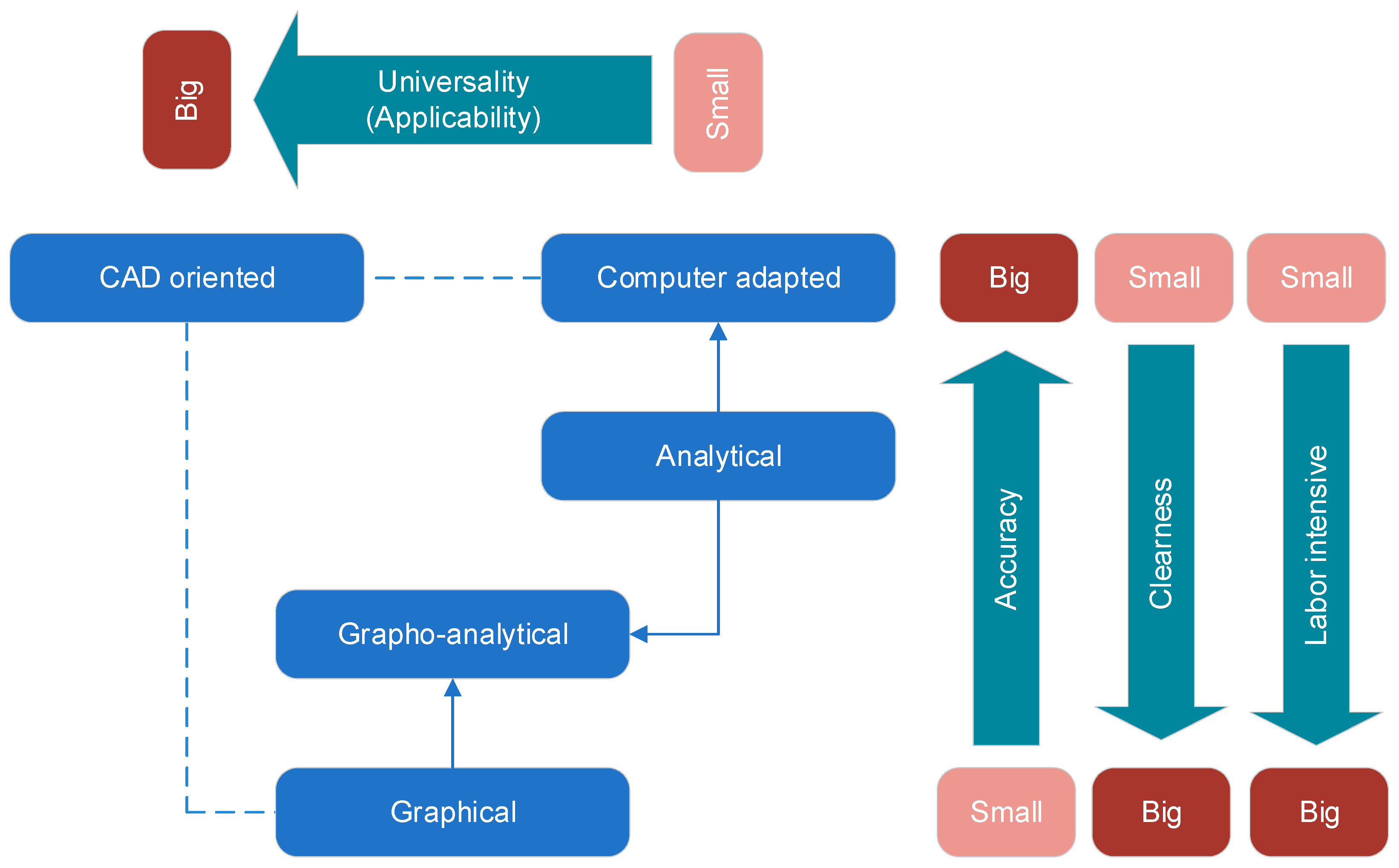
Figure 1 shows a flowchart with the main characteristics determining the applicability of the methods of forming threads [
1,
2].
2.2. Forming of Internal Threads by Milling
Forming internal threads by cutting is the most common method. Internal threads can be formed with thread-turning tools, taps, disk thread-milling cutters, thread-milling cutters and thread-cutting heads [
1,
2]. In practice, forming internal threads is mainly realized with thread-milling cutters.
Short internal threads with fine and normal pitches are made with thread-milling cutters. The method of cutting threads with thread-milling cutters is performed on special thread-milling machines or CNC machines under conditions of medium and mass production. These tools in certain cases successfully replace thread-cutting taps, especially when cutting threads in body parts, due to the fact that when the tool is destroyed, the geometric characteristics of the machined threaded surfaces remain intact. The disadvantages of this type of tool include the deviations in the profile of the formed thread due to the thread-forming scheme and the design features of the tools. These deviations are reduced by implementing a new working profile of the cutters determined by profiling.
During operation, the tool axis is parallel to the workpiece axis. The working movements performed by the thread-milling cutter are shown in
Figure 2 and
Figure 3. Milling of internal threads is realized by the main rotary movement 1, radial feed movement 2, circular feed movement 3 and longitudinal feed movement 4. The thread-milling cutter cuts radially into the workpiece with movement 2 until the complete profile of the thread is formed. The thread is formed by up-milling while performing a circular feed movement 3 and axial movement of the tool with a movement 4 equal to the thread pitch P.
The forming of internal threads by milling is performed on CNC machines, and specifically on machining centers, because of their capabilities to provide the complex combinations of main and feed-forming movements. CNC systems contain a variety of automated cycles for thread processing. Through them, high accuracy and efficiency of processing is achieved, significantly reducing machine times [
3,
4,
5].
Despite the many sources of information on the process of milling internal threads with thread-milling cutters, there are many issues that have not been sufficiently addressed. For example, questions about solving the problem of determining the tool profile to compensate for deviations from the theoretical profile due to the parallelism of the axes of the tool and the workpiece, the formation of helical chip flutes or the presence of a rake angle. There are also issues related to technological and design errors when milling internal threads, etc.
Figure 4 shows the methods used for profiling the working part of metal-cutting tools.
The classical methods for profiling cutting tools are the grapho-analytical methods. In this type of design, part of the input data for the analytical part of the profiling is taken from graphical schemes developed on a scale with high magnification. However, their accuracy is relatively low. Grapho-analytical methods are used to verify the results of classical analytical modeling.
With the advent of modern CAD systems for three-dimensional modeling, the need for such scaling disappears because it is possible to work with the real dimensions of the products, and the accuracy with which the graphic schemes are measured, for example in the CAD system SolidWorks, is eight digits after the decimal point. The required accuracy, which is usually used when profiling the cutting tools, is high, at four digits after the decimal point. In this way, the use of modern CAD systems completely replaces the classical methods of grapho-analytical design, and there is no need to check the results analytically.
Profiling is used in the manufacture of various types of metal-cutting tools. Through analytical or graphical profiling, the working parts of the tools are obtained, which in most cases represent surfaces with a complex shape. Such tools are, for example, thread-turning tools [
1,
2], taps [
1,
2], dies [
1,
2], thread-cutting heads [
1,
2], finger-milling cutters [
1,
2], end mills [
1,
2,
6,
7,
8,
9], thread-milling cutters [
1,
2,
10], disk-shaped thread-milling cutters [
1,
2,
11], ring-shaped tools for vortex thread milling [
12], combined tools [
13,
14], profile turning tools [
15,
16,
17], gear-shaped cutters [
1,
2,
18], profile milling cutters [
19], single-tooth thread-milling cutters [
20] etc.
The publication considers the profiling of the working part of thread-milling cutters by an analytical method and by a graphical method using a CAD system. The profiling of tools for forming metric threads is considered. These are the threads that are widely used in practice. If a tool needs to be designed for another type of thread, the proposed method for graphic profiling can be used. The method is applicable for all types of threads that have a straight profile.
3. Analytical Determination of the Tool Surface Profile of Thread-Milling Cutters for Milling Internal Threads
When milling threads with thread-milling cutters, the tools are oriented relative to the machined surface so that the axis of the rotary profile working part of the tool is parallel to the geometric axis of the machined thread. This positioning of the tool relative to the milled surface leads to deviations in the axial profile of the latter. The forming of the specified axial profile of the formed surface without deviations is achieved by implementing special profiling of the tool surface.
To determine the profile of the tool surface on which the cutting edges of the teeth are located, with a known profile of the formed surface, an analytical method was used. Using a graphical method, the same profiling of the tool surface was performed through the SolidWorks 2022 CAD system, and its accuracy and reliability were validated.
3.1. Methodology for Analytical Determination of the Profile of the Tool Surface
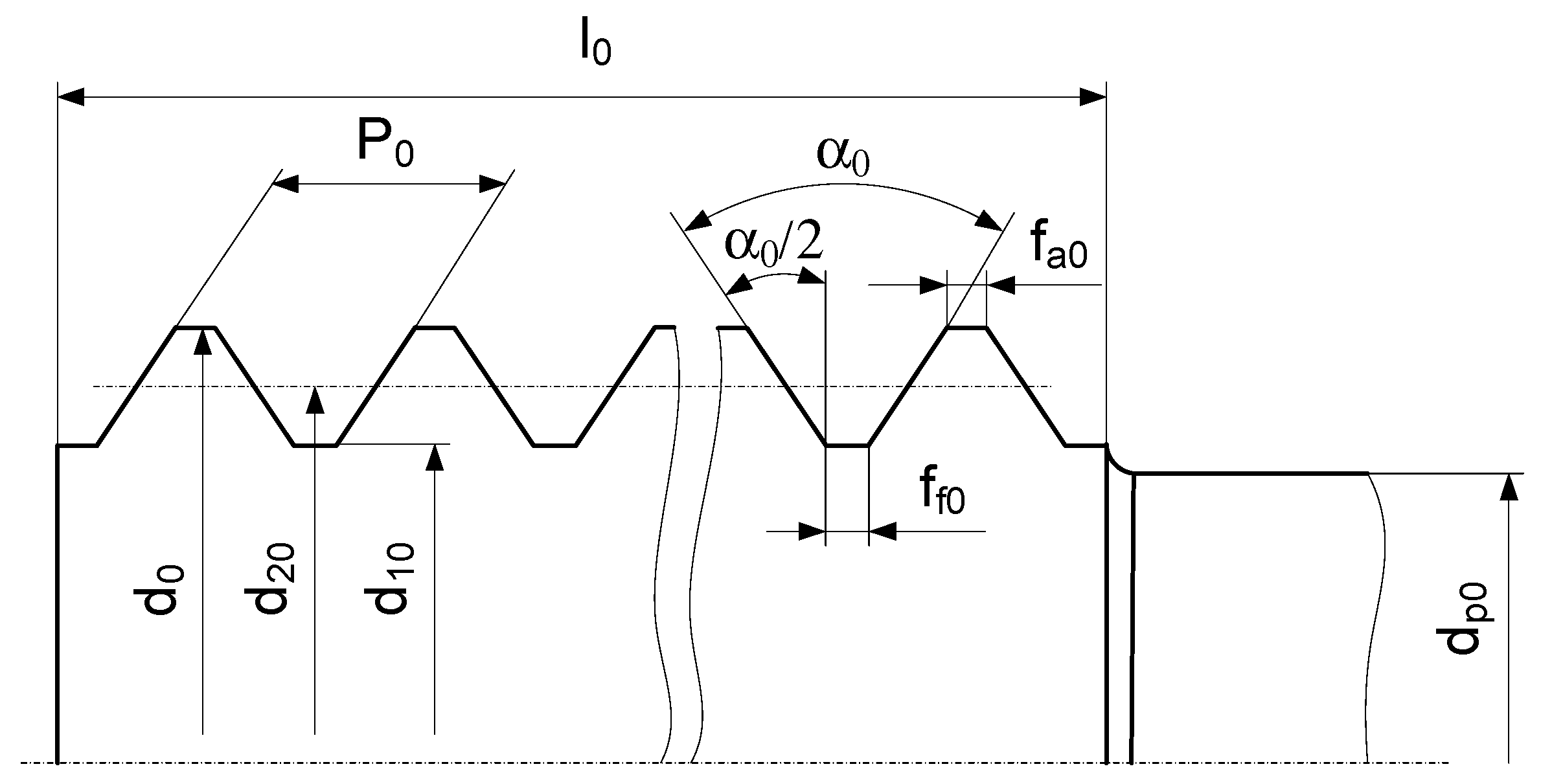
Figure 5 shows the profile of an internal thread in cross- and axial section.
A thread whose profile in axial section is linear is defined as an Archimedean helical surface. Any section of it normal to its geometric axis, for example, section A-A in
Figure 5, is an Archimedean spiral with an equation in polar coordinates:
where R
i is the radius vector of the Archimedean spiral in mm; a is parameter of the Archimedean spiral in mm/rad; φ
i is the angle of rotation of the spiral in rad.
These cross-sections are identical but are rotated relative to each other by an angle ε
i, depending on the helical parameter of the helical surface (
Figure 6):
where
is a helical parameter; P is the thread pitch in mm; n is the number of thread passes; z
i is the displacement of the secant plane along the “z” axis in mm.
The secant plane A-A also intersects the rotational tool surface oriented in the “Oxyz” coordinate system. Its section in the same secant plane is a circle with diameter d
0i, which is tangent to the Archimedean spiral S at point i, where they have a common normal passing through points i and 1′ (
Figure 6). This section is a profiling section of the tool surface. Since the rotary tool surface has a smaller diameter than the inner diameter of the thread, the center distance A
0 is set, which is determined by the following equation:
where R is the radius of the outer diameter of the thread and r
0 is the radius of the circle of the tool tangent to the outer diameter of the thread in mm.
The circle drawn with radius A
0 is the trajectory of the circular feed motion 3 (
Figure 2 and
Figure 3). In order to realize the milling, it is necessary that the normal vector at any point of the spiral describing the cross-section of the thread intersects this circle.
Considering that with known pitch P, number of thread passes n, average diameter D
2 and thread profile angle α each helical surface is determined, then Archimedean spirals are also determined, drawing the different sections that the tool touches. Their parameter “a” can be determined by the following equations:
where R
0 is the radius vector of point 0 of the Archimedean spiral drawn at angle φ
0 in mm; R
6 is the radius vector of point 6 on the same spiral, but at an angle φ
6 in mm; H is the height of the theoretical thread profile in mm.
The radius vectors of the spirals increase from R
6 to a value of R
0 for an angle
. Then, from Equation (7), it follows that
, and taking into account Equation (6), for the spiral parameter, the following equation is obtained:
For a certain parameter of the spiral “a” and given radius vectors R
i at different points in the range R
1 ÷ R
6, the angle of rotation of the spiral φ
i is determined. For each value of φ
i, the position of the secant plane z
i in the coordinate system “Oxyz” is also determined by the following equation (
Figure 7):
To determine the radii of the tangent (profiling) circles at any point “i”, it is necessary to know the coordinates of the tool center. To determine them, the equation of the circle with radius A0 describing the trajectory of the center of the tool surface and the equation of the normal to the Archimedean spiral at the i-th point in the “Oxyz” coordinate system is used.
The equation of the circle is as follows:
The equation of the normal at any contact point “i” is determined by the following equation:
where
By solving (10) and (11) together and taking into account (12)–(14), after processing, the following quadratic equation is obtained:
Taking into account that
Equation (15) becomes
The elements of the equation are as follows:
These are the abscissas of the intersection points 1′ and 2′ of the normal with the trajectory of the tool center (
Figure 6).
Using Equation (11) with known abscissas x
1′ and x
2′, the values of the ordinates of the intersection points y
1′ and y
2′ are also determined. In order to determine the diameter of the profiling circle d
0i, the distances l
1′ and l
2′ between these points and point “i” are determined according to the following equations:
The radius of the profiling circle r0i is assumed to be equal to the smaller value of l1′ or l2′.
The forming line of the profile of the disk tool is obtained from the series of values of z
0i and r
0i and drawing the symmetrical profile (
Figure 8).
By ignoring the slight curvature of the side forming the profile and replacing it with a straight line that passes through points 1 and 5, the profile angle of the axial profile of the producing tool surface is also determined (
Figure 8).
After replacing the resulting profile curve with a straight line passing through points 1 and 5, the difference between the thread profile angle α and the tool surface profile angle α
0i (i = 5) is determined. This difference is taken as the necessary correction Δα
0 of the tool surface profile and is determined by the following equations:
where z
1 is the applicate of point 1 of the profile, determined by Equation (9) at i = 1 in mm; R
imax is the maximum radius of all radius vectors R
i, determined by Equation (1), in mm; r
0imax is the maximum radius of all radii of the profiling circle r
0i, determined by Equations (22) and (23), in mm.
Using the developed analytical profiling methodology, a Microsoft Excel 2019 program was created to determine the profile of the tool surface. It is assumed that the coordinates of five points of the thread profile are calculated (
Figure 8).
Table 1 summarizes the methodology for determining the parameters of the tool surface profile. The parameters and equations used to determine them are shown.
3.2. Application of the Methodology for Analytical Determination of the Tool Surface Profile
According to a developed methodology for analytical determination of the profile of the tool surface, an example of determining the parameters of a thread-milling cutter for cutting internal threads has been solved. The tool surface of a thread-milling cutter M10 × 1, with which an internal metric thread M20 × 1 is formed, is determined.
Table 2 shows the results of solving the problem.
The calculations were made with the program based on Microsoft Excel 2019. The program contains all the equations from
Table 1. The diameter of the thread-milling cutter d
0 and the type of thread that will be formed are entered into the program. After that, the program calculates the parameters of the tool surface.
The designation used for the thread-milling cutter M10 × 1 means M—metric thread, 10—minimum size of the formed thread and 1—thread pitch, P. The same approach is used for the designations of all thread-milling cutters in the publication.
With the values obtained for the points of the tool surface profile, it can be manufactured. Each tooth of the thread-milling cutter must be machined with such a surface. The tool surface obtained by the analytical profiling method is such that when the tool is operated, there is no trimming of the profile of the formed thread.
4. Graphical Determination of the Tool Surface Profile of Thread-Milling Cutters for Milling Internal Threads
4.1. Methodology for Graphical Determination of the Tool Surface Profile
The graphical method for determining the tool surface was developed using the SolidWorks 2022 CAD system [
21]. Profiling is performed in the following sequence:
- -
The main parameters of the formed internal thread D, D2, D1, P and α are defined.
- -
A three-dimensional model of the internal thread is drawn according to the specified parameters.
- -
The main design parameters of the milling part of the tool d
0, d
20, d
10, P
0 and α
0 are defined (
Figure 9).
- -
The radius A0 is determined according to Equation (29), and the trajectory is drawn that describes the center of the milling part of the tool during the milling process,
where D is the outer diameter of the formed thread in mm; d
0 is the outer diameter of the milling part of the tool in mm.
- -
Secant planes intersecting the theoretical profile of the thread with height H from point 1 to point i at distances from z
1 to z
i along the axis of the thread are built (
Figure 10).
The larger number of secant planes determines the larger number of points to describe the profile of the tool surface. This increases its accuracy.
- -
In each secant plane, circles with diameters d
10S, d
20S, d
30S, … d
i0S are drawn from the tool surface, which are tangent at points 1, 2, 3, … i of the Archimedean spiral and have a center lying on the circle with radius A
0 (
Figure 10).
In
Figure 10 these circles are drawn only in section A-A; therefore, they are rotated by a certain angle ε
i proportional to the distances z
i and determined by Equation (2). The circles defining the tool surface profile are shown in
Figure 11.
- -
The coordinates of points 1, 2, 3, … i in the “Oxyz” coordinate system are determined, which are necessary for constructing the tool surface and are obtained in the different cross-sections corresponding to the diameters d
10S, d
20S, d
30S, … d
i0S (
Figure 12).
- -
The profile of the tool surface is drawn by connecting points 1, 2, 3, … i with a spline line (
Figure 12).
After connecting the points with a spline, the theoretical tool surface of the milling part of the tool is obtained that does not trim the thread profile. The resulting profile has a convex shape.
- -
The coordinates of the points on the tool surface corresponding to the main diameters of the tool profile d
0, d
20 and d
10 are determined (
Figure 13).
With a known radius A
0 of the circle that describes the milling part, the positions of the tool diameters d
0, d
20 and d
10 are determined in secant planes through the tool surface obtained by profiling at points 1
0, 2
0 and 3
0. The points are located at distances z
10, z
20 and z
30, corresponding to the location of the diameters of the internal thread D, D
2 and D
1 (
Figure 13).
- -
The tool surface profile obtained after profiling is replaced with straight lines (
Figure 14).
The defined profile uses curvilinear forming. Curves are replaced by straight lines from point 1
0 to point 3
0 (
Figure 14). As a result of the replacement, the deviation of the profile δ
0 is obtained. The profile of the new tool surface is obtained with a profile angle α
0 < α as well as a width at the tip f
a0 < f
f, where f
f is the width of the groove of the internal thread.
The size of the error δ0 is influenced by the pitch P of the formed thread, the outer diameter of the milling part d0 and the ratio between the diameters of the milling part of the tool and the outer diameter of the thread d0/D, that is, the maximum diameter of the internal thread that can be machined with a given diameter of the milling part.
Figure 15 shows the profiling of the tool surface of a thread-milling cutter M10 × 1 using the CAD system SolidWorks 2022. The results of the profiling can be seen in
Section 5.2. The graphical profiling of the tool surface of milling cutters for forming threads M10 × 1, M16 × 1.5 and M20 × 20 was made. The methodology described in
Figure 15 was used for profiling.
Profiling with the SolidWorks 2022 CAD system includes the following stages:
- -
A three-dimensional model of a part with an internal thread M10 × 1 is drawn.
- -
In a plane built in the cross-section, the profile of the internal thread with diameters D, D
2 and D
1 is drawn. In this way, the position of points 1, 2 and 3 is defined (
Figure 15a).
- -
Planes are built in the axial section passing through points 1, 2 and 3 (
Figure 15b).
- -
In the plane passing through point 1, a circle with radius r
0 is drawn tangent to a point of the Archimedean spiral and with a center lying on the circle with radius A
0 (
Figure 15c). The circle corresponds to the diameter of the instrument d
0.
- -
In the plane passing through point 2, a circle with radius r
20 is drawn tangent to a point of the Archimedean spiral and with a center lying on the circle with radius A
0 (
Figure 15d). The circle corresponds to the diameter of the instrument d
20.
- -
In the plane passing through point 3, a circle with radius r
10 is drawn tangent to a point of the Archimedean spiral and with a center lying on the circle with radius A
0 (
Figure 15e). The circle corresponds to the diameter of the instrument d
10.
- -
A new sketch is built on which the resulting tangent circles with radii r
0, r
20 and r
10 are drawn, which form the profile of the tool surface in cross-section (
Figure 15f). From the sketch, information is obtained about the profile height h
0i and the angle of the tool surface profile α
0i.
4.2. Graphical Determination of the Influence of the Rake Angle and the Height of the Backing off on the Tool Surface
The profile of the tool surface is influenced by the rake angle γ0 and the backing off K0. They lead to a tooth profile that is different from that in the axial section, i.e., a profile with a different height h0 and a different profile angle α0. The values of the rake angle γ0 depend on the mechanical characteristics of the material being processed and are in the range 0÷10°, and the height of the backing off K0 determines the values of the back angle at the top points.
The graphical method for determining the influence γ
0 and K
0 was developed using the CAD system SolidWorks 2022 [
21]. The profile of the tool surface obtained by analytical or graphical profiling methods is taken as a starting point.
The graphical method is performed in the following sequence:
- -
The coordinates of the points on the tool surface corresponding to the main diameters of the tool profile d
0, d
20 and d
10 are determined (
Figure 16).
With a known radius of the circle A0, which describes the milling part, the position of the tool diameters d0, d20 and d10 is determined in secant planes through the tool surface obtained by profiling. The secant planes are located at distances corresponding to the location of the internal thread diameters D, D2 and D1.
- -
A secant plane A-A is constructed at a point corresponding to the outer diameter d
0 of the milling part of the tool (
Figure 16).
- -
Graphical builds are made in the secant plane at different rake angles, varying from γ
0 to γ
0i, to determine the heights of the profile along the front surface, varying from h
0 to h
0i (
Figure 17).
As the rake angle γ0 increases, the profile height also increases, while its width remains constant.
The influence of the height of the backing off K
0 on the profile angle α
0 is expressed in the presence of the rake angle γ
0. Using the graphical builds shown in
Figure 17, the height of the backing off K
0 is also added (
Figure 18).
When the rake angle changes from γ
0 to γ
0i and there is a backing off height K
0, the profile height of the tool surface changes from h
0 to h
0i, which changes the profile angle from α
0 to α
0i and leads to a deviation of the angle Δα
0 at a constant tooth width b
0 (
Figure 19).
To form an accurate thread profile, it is necessary to take into account the deviation Δα
0 of the profile angle:
The resulting difference ΔK0 does not affect the accuracy of the thread, since the latter depends on the accuracy of the realization of the center distance.
Figure 20 shows the determination of the influence of the rake angle and the height of the backing off on the tool surface of a M10 × 1 thread-milling cutter using the SolidWorks 2022 CAD system.
The results of the profiling can be seen in
Section 5.3. The graphical profiling of the tool surface of the milling cutters M10 × 1, M10 × 1.5 and M10 × 2 was performed, which were used to form internal threads with diameters from M10 to M24 with thread pitches P1, P1.5 and P2 mm. For each of the variants, the corresponding three-dimensional models and sketches were developed in SolidWorks 2022. The methodology described in
Figure 20 was used for profiling.
Determining the influence of the rake angle γ0 and the backing off height K0 with the SolidWorks 2022 CAD system includes the following stages:
- -
A three-dimensional model of a part with an internal thread M10 × 1 is drawn.
- -
The coordinates of the points of the tool surface 1 and 3, corresponding to the diameters of the tool profile d0 and d10, are determined in advance. The coordinates of the points are obtained from the analytical or graphical profiling of the tool surface of the thread-milling cutter.
- -
A plane is drawn in the axial section passing through point 1 (
Figure 20a).
- -
In the plane with a known radius of the circle A0, which describes the milling part, circles with radii r0 and r10 are drawn through the points corresponding to the tool diameters d0 and d10.
- -
Graphical builds are made in the secant plane, corresponding to the rake angle γ0i—0°, 3°, 5° and 10°. In this way, the heights of the profile along the front surface from h0 to h0i are determined.
- -
A curve corresponding to the backing off height K0 is drawn.
- -
A new sketch is drawn on which the resulting tool surface is drawn in cross-section (
Figure 20b). From the sketch, information is obtained about the profile height h
0i and the tool surface profile angle α
0i at different values of the rake angle γ
0i.
5. Research Methodology and Experimental Results
5.1. Deviations Inherent in the Thread-Milling Scheme with Thread-Milling Cutters Determined by the Analytical Method
Through the developed analytical method for profiling, the deviations of the profile angle of the milling part were determined as Δα
0. The influence of the change in the diameter of the internal thread D on the profile angle α
0 at different ratios of the diameters of the tool and the thread d
0/D, as well as at a certain pitch of the thread P, was studied. The rake angle of the front surface is γ
0 = 0°. The forming of internal threads of different diameters with thread-milling cutters M10 × 1, M10 × 1.5 and M10 × 2 was studied. Threads M10, M12, M14, M16, M18, M20, M22 and M24 are formed with steps P1, P1.5 and P2. The results obtained are given in
Table 3.
Based on the calculations made, the following conclusions can be drawn:
- -
It was found that with an increase in the diameter of the thread D, at a constant pitch of the thread P and a constant outer diameter of the tool d0, the deviation of the profile angle of the tool surface Δα0 decreases;
- -
It was found that increasing the pitch of the internal thread P leads to an increase in the deviation of the profile angle of the tool surface Δα0;
- -
It was found that with an increase in the ratio of the diameters of the tool and the thread d0/D at a constant pitch of the thread P, the deviation of the profile angle of the tool surface Δα0 increases.
5.2. Graphical Verification of the Analytical Profiling Method
In order to compare the results obtained by the analytical or graphical method, the task of determining the profile of the tool surface was solved by both methods when forming different internal threads—thread M10 × 1 with a thread-milling cutter M10 × 1, thread M16 × 1.5 with a thread-milling cutter M10 × 1.5 and thread M20 × 2 with a thread-milling cutter M10 × 2. For the graphical method, the results were obtained from the three-dimensional models and sketches developed for each of the variants with the SolidWorks 2022 CAD system.
For both solutions of the task, the profile is defined in three points—point 1, point 3 and point 5 (
Figure 8), with the corresponding radii R, R
2 and R
1. The obtained results are presented in
Table 4,
Table 5 and
Table 6.
Based on the calculations made, the following conclusions can be drawn:
- -
It was found that the values of the profile parameters of the tool surface obtained analytically and graphically differ minimally. The difference obtained is after the third decimal place. The reason for this is the use of input data with values accurate to the fourth decimal place when drawing three-dimensional models, which leads to the accumulation of errors, as well as the permissible minimum deviations that SolidWorks 2022 gives when drawing helical lines and, from there, Archimedean spirals.
- -
It was found that high-accuracy results are obtained that are fully sufficient for the construction of the tool surface.
- -
It was proved that the replacement for technological reasons of the curvilinear of the tool surface profile obtained after profiling by analytical or graphical methods with a straight line causes insignificant deviations of the profile δ0.
5.3. The Influence of the Rake Angle and the Backing Off on the Tool Surface
The deviations of the height of the profile h
0 and of the profile angle of the milling part Δα
0 were determined by the developed method. The influence of the rake angle γ
0 and the diameter of the internal thread D on the profile angle α
0 was studied with a certain pitch of the thread P and at different ratios of the diameters of the tool and the thread d
0/D. Forming of internal threads from M10 × 1 to M24 × 1 with an M10 × 1 thread-milling cutter, threads from M10 × 1.5 to M24 × 1.5 with a M10 × 1.5 thread-milling cutter, and threads from M10 × 2 to M24 × 2 with an M10 × 2 thread-milling cutter was considered. The results were obtained from the three-dimensional models and sketches developed for each of the variants with the SolidWorks 2022 CAD system. Results are presented in
Table 7.
Based on the calculations made, the following conclusions can be drawn:
- -
It was found that when milling internal threads with tools with a constant outer diameter d0 and backing off height K0, with an increase in the rake angle of the teeth γ0 of the milling part, the height of the profile h0 and the deviation of the profile angle of the tool surface Δα0 increase, and the width of the teeth b0 remains constant;
- -
It was found that with an increase in the diameter of the internal thread D at a constant pitch of the thread P and a constant external diameter of the tool d0, the profile height h0 and the deviation of the profile angle of the tool surface Δα0 decrease;
- -
It has been proven that in order to obtain an accurate profile of the internal thread, it is necessary to correct the profile of the tool surface by Δα0 and ΔK0.
6. Application of Analytical and Graphical Profiling in the Design of Thread-Milling Cutters
The presented methods for profiling the tool surface of internal thread-milling tools have been used in the development of various designs of thread-milling cutters. The following figures present three-dimensional models of tools that are parametrically modeled through configurations. A modeling approach was used in which configurations represent different variants and variations in the models [
22].
A specialized methodology was developed to determine the design parameters of the thread-milling cutters. Through the methodology, the equations were determined according to which the parameters of the individual elements of the tool are calculated—milling part, transition part and shank. A Microsoft Excel 2019 program was developed with which the parameters of the thread-milling cutters are determined depending on the internal thread that needs to be formed.
Figure 27 shows the design of a thread-milling cutter designed for forming internal threads with diameters from 6 to 25 mm on CNC machining centers with three or more controlled axes.
The tool consists of a working part and shank 3. The working part consists of a milling part 1 and a transition part 2. The milling part has a length of 2D, where D is the diameter of the formed thread.
Figure 28 shows parametric models of the thread-milling cutter representing different designs with straight and helical flutes. The parameters of the milling part and the shank are parametrically modeled.
Design documentation has been prepared for the presented tools for forming internal threads using the SolidWorks 2022 CAD system. The process is automated by using template files for the three-dimensional models and drawings. Attributes (users and systems ones) are filled in the three-dimensional model templates, after which the information from them is visualized in the tables of the drawings [
22].
Figure 29 and
Figure 30 show the developed drawings of the two models of thread-milling cutters.
7. Discussion
The shaping of internal threads by cutting is performed by various methods using tools such as thread-turning tools, taps, thread-milling cutters and thread-cutting heads. Among them, the highest productivity and efficiency is achieved when milling with thread-milling cutters.
The design and manufacture of such tools requires an accurate definition of the tool surface. In this regard, two approaches are presented—analytical and geometric profiling. A comparison of the results shows that both methods give very close values when determining the points of the tool surface.
An analytical method has been developed to determine the profile of the working part of the thread-milling cutters. The developed methodology calculates the points of the profile of each tooth that build the tool surface. For this purpose, a Microsoft Excel 2019-based program has been developed that automatically calculates these points. The obtained parameters allow the design and manufacture of a thread-milling cutter for a specific internal thread or for a group of threads.
In parallel, a graphical method for profiling the tool surface using a CAD system is proposed. This method provides a profile in which the helical surfaces of the formed thread are not trimmed. The implementation using SolidWorks 2022 allows for the assessment of the resulting profile deviations when milling internal threads. The graphical method based on enveloping curves forms the profile by multiple circles that are tangent to an Archimedean spiral in axial section and intersect the thread profile in cross-section. Compared with classical analytical approaches, the proposed graphical methodology allows for a more intuitive verification of the profile and easier application when working with non-standard thread and/or helical profiles.
One of the main advantages of the proposed graphical method is that it is easy to use and implement in CAD software. This makes it accessible even to engineers who may not have much experience in mathematical modeling. Although analytical methods remain more precise from a theoretical perspective, the graphical method is accurate enough for practical applications and helps speed up the design process.
The influence of the design parameters rake angle γ0 and the backing off K0 on the profile of the cutting edge has been assessed. The analysis shows that at constant values of the outer diameter d0 and the backing off K0, increasing the rake angle γ0 leads to an increase in the height of the profile h0 and an increase in the deviation of the profile angle Δα0. When the thread diameter D increases, at a constant pitch P and tool diameter d0, an opposite trend is observed—the height of the profile h0 and the deviation of the profile angle Δα0 decrease. It has also been established that to achieve an accurate profile, it is necessary to correct the profile of the tool surface by Δα0 and ΔK0.
The verification of the results obtained by the analytical method was carried out with the graphical method. Both approaches achieved similar values for the profile parameters. The accuracy of the obtained results is sufficient for the design and subsequent production of a specific thread-milling cutter.
A program has been created in Microsoft Excel 2019 to determine the design parameters of the thread-milling cutter—including the milling part, transition part and the shank. On this basis, designs of thread-milling cutters for internal threads have been developed. Geometric and design parameters have been determined using the analytical and graphical methods. Parametric three-dimensional models have been created in the CAD system and the process of creating design documentation automated using template files. User and system attributes are entered into these files, which are also used in the drawings. Information from the attributes can be used for documentation management through a PDM system as well as by other departments in the company through an ERP system.
However, the methods have their limitations. The results depend on the accuracy of the entered parameters and the CAD environment. The influence of real production factors such as wear, deformations and sharpening errors is not automatically taken into account—these factors are taken into account in the process of the final design of the tool by setting the necessary tolerances, which take into account the type of machining, the type of material being processed, the type of tool material as well as other elements of the cutting mode.
The presented methodology can be used directly in engineering practice, especially in small and medium-sized companies. The methodology is intended for profiling tools for forming all types of threads that have a straight profile. Another advantage is the possibility of the tools having a rake angle γ0 different from 0°.
After some additional work, the methodology could be extended to design tools for machining external threads. The same methodology could also be used to profile tools for complex-profile helical surfaces and threads whose profiles are not linear as are the metric threads presented in this publication.
8. Conclusions
The paper proposes and evaluates a graphical profiling method referred to as the Tangent Circles Method. The method for graphical profiling of the tool surface of thread-milling cutters for internal threads is studied. It is based on the use of tangent circles and is implemented in a CAD environment. The method is validated by comparison with results obtained using the analytical method. Simulations with different parameters are also performed. The results show a very good match between the graphical and analytical approaches. The differences in the profile angle are minimal and within the tolerances for real manufacturing.
The graphical method has several practical advantages. It enables quick profile visualization. It is easily performed using a standard CAD system. It requires fewer calculations. It is suitable for designers and technologists who work with tight deadlines and with limited resources. It can also be applied to non-standard tools where analytical approaches become too complex and difficult to apply and require high mathematical knowledge.
The results demonstrate that the Tangent Circles Method is a reliable and effective technique for modeling complex tool geometries using CAD systems. Its ease of use and good accuracy make it a practical alternative to conventional analytical techniques. The method has strong potential for broader application in the design of advanced cutting tools and may be further implemented in automated tool-design systems or extended to support non-standard thread geometries.
However, the method has its inherent limitations. It depends on the accuracy of the CAD software and the correct setting of the parameters. In case of errors in the geometry or insufficient resolution, deviations occur. The method does not take into account the influence of mechanical deformations, wear or sharpening errors.
A positive aspect of the presented work is the analysis of the influence of the rake angle γ0 and the backing off K0 on the profile of the tools. It is shown that these parameters have a significant influence on the profile of the cutting edges. By changing the rake angle, the height and inclination of the working surface change. With a combined change in γ0 and K0, a visible deviation from the ideal profile is obtained. This shows that profiling should not be considered in isolation. It should be taken into account with the design and technological characteristics of the tool.
The comparative analysis between the analytical and graphical methods confirms the reliability of the tangent circle approach. For different threads and tools, it has been found that the results of the two methods differ by less than one tenth of a degree in the profile angle. This is completely acceptable in design and production.
The proposed graphical method of Tangent Circles is suitable to be used in manufacturing. It is accurate enough for real applications. It is easy to implement and understand. The authors support the idea that this method is also suitable for small and medium-sized companies where the necessary time cannot be allocated and there are no resources or capacity for full analytical modeling. However, if the task has increased accuracy requirements, or when profiling tools is characterized as critical, the proposed method should be used in combination with analytical analysis or with real verification of the results in production.


