1. Introduction
As widely recognized, Geometric Dimensioning and Tolerancing (GD&T) is a method for specifying and conveying engineering tolerances on engineering drawings and computer-generated 3D models, using a symbolic language that explains the nominal geometry of a physical object and the acceptable variations from it [
1]. The nominal (theoretically perfect) geometry of parts and assemblies, the permitted variation in the size, form, orientation, and location of individual features, and how features may differ from one another so that a component is deemed adequate for its intended use are all defined by GD&T. This framework addresses traditional subtractive manufacturing techniques like machining, turning, and milling, and establishes geometric and dimensional criteria for designed components [
2,
3]. These processes allow the production of either simple parts with prismatic or revolving features or more complex geometries (especially when CNC machine centers are adopted); in any case, such parts are characterized by a well-defined topology and, depending on the process itself, by specific and usually consistently annotatable tolerance values. Quite the reverse, Additive Manufacturing (AM) enables the creation of complex geometries and freeform shapes that challenge traditional tolerancing approaches [
4]. Mainly due to the special features of additive processes, including layer-by-layer fabrication, the manufacturing of complex geometries, and material variability, the adoption of GD&T in AM is expected to be significantly developed in the next years. Standardized techniques to properly specify and communicate dimensions and geometric tolerances of additive manufactured parts will be required to deal with issues like the implementation of topology-optimized designs, surface roughness, and the presence of anisotropic features on a macroscopic scale (e.g., resulting from layer-by-layer manufacturing) and on a microscopic scale (e.g., due to the thermal history in the AM process). In particular, the main challenge is to ensure that AM components fulfill functional requirements while aiding efficient production and quality control, especially when integrated into machines composed of both subtractive manufactured and AM components. To achieve dimensional compliance with the original CAD model, some approaches are used to manage geometric, dimensional, or shape errors in AM. For instance, stair-stepping, a rough surface caused by AM’s layer-by-layer bottom-up method, can potentially result in a geometrical error. Along with component shrinkage, these geometrical errors are also influenced by material qualities, process parameters, support structures, and surface approximation errors brought on by slicing techniques. As a consequence, the design phase needs to take into account the expected actual geometry of the manufactured parts, planning a set of actions to ensure its compliance with the originally designed digital part. Accordingly, the geometrical mismatch between the printed items and the CAD and toolpath models is a significant problem to be confronted with when AM is involved as a primary method for building a part [
5]. Because of the alterations made during the slicing step to build a toolpath model that depends on different slicing settings, the printed part is not the same as the original CAD model. The goal is to reduce the deviations and/or compensate them based on the process conditions [
6]. However, to function as a comprehensive geometric quality sensing and control strategy, the integration of GD&T and AM requires considerable development. According to recent literature [
6,
7,
8,
9,
10], the key perspectives for integrating GD&T and AM can be categorized into the following issues:
Adaptation of GD&T principles to AM-specific geometries
Surface texture and tolerance stack-up
Digital thread and model-based definition [
11]
The advent of Artificial Intelligence in GD&T
Standardization of inspection for AM
GD&T adaptation to different technologies
GD&T in AM assembly parts
The present Perspective Paper aims to briefly hint at key challenges for the future of GD&T in AM, with an eye to the necessary adaptation of tolerancing principles to AM-specific geometries, integration of Model-Based Definition (MBD) in digital threads, and development of new standards for surface texture and tolerance stack-up. This will act as a basis for stimulating a discussion within the scientific community on this fascinating topic that will be prominent shortly in manufacturing and industrial fields.
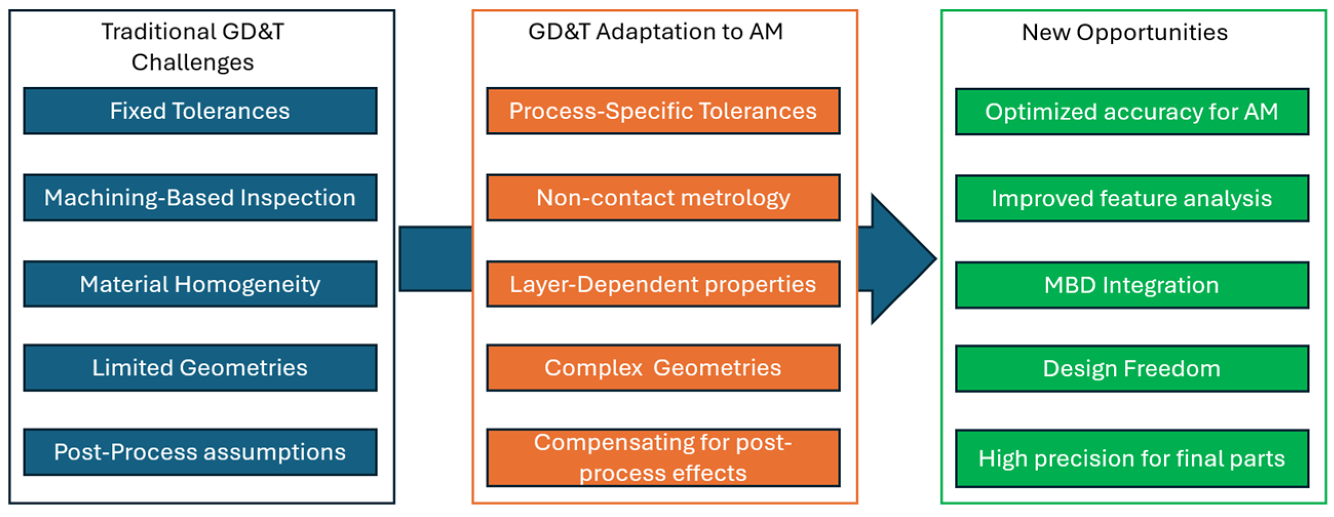
Figure 1 shows a conceptual schematic illustrating the adaptation of GD&T principles to Additive Manufacturing.
2. Adaptation of GD&T Principles to AM-Specific Geometries
As mentioned above, differently from subtractive manufacturing, AM introduces some design complexities such as organic geometries, the presence of internal features, and, possibly, lattice structures. Dealing with non-Euclidean surfaces, these are difficult to dimension and tolerate using conventional GD&T standards. By way of example, lattice structures or gyroids used in lightweight aerospace components may not have clearly defined planes, axes, or cylinders for referencing traditional datum systems. For what concerns internal features, such as channels, cavities, and voids, the main issue is related to their inaccessibility for measurement using traditional inspection tools like coordinate measuring machines (CMMs); as a consequence, it is not trivial to determine the actual dimensions of such features, despite the fact that this challenge is shared with the field of precision casting, where several techniques can also be adapted to AM. Finally, the layer-by-layer process in AM results in anisotropic material properties and dimensional variation due to factors like residual stress, heat distortion, or powder bed characteristics. This makes it difficult to define a set of geometrical tolerances on the part.
To address these challenges, GD&T is rapidly evolving to encompass functional datum systems that can reference freeform surfaces instead of relying on idealized planes or cylinders [
12,
13]. Therefore, future GD&T practices will integrate surface profile tolerancing for freeform surfaces using methods such as point cloud analysis or mesh comparison to verify the manufactured geometry against the design intent. Not by chance, ISO 21920-1:2021 [
14] and ASME Y14.46 [
15] (under development for AM-specific GD&T) define a set of parameters for surface texture, including those suitable for irregular shapes produced by AM. AM has been used by businesses like Rolls-Royce and GE Aviation for manufacturing engine parts with complex geometries, such as fuel nozzles. Tolerances for freeform surfaces and functional interfaces need to be defined for these components using GD&T modifications. Another example is provided by freeform designs customized to each patient’s anatomy, which are used in patient-specific implants, such as those made with AM for orthopedics. Instead of using traditional dimensions, GD&T standards should be adopted to include tolerances for fitness and function.
3. Surface Texture and Tolerance Stack-Up
Since AM is mostly layer-by-layer based, tolerance stack-up and surface texture requirements are different from those adopted in conventional manufacturing. Layer thickness, material deposition technique, powder size, and post-processing methods are some of the parameters that affect both the final shape of the part (which deviates from the designed part and the traditional machined surfaces) and the surface finish in AM parts. These variations provide difficulties for conventional GD&T procedures and ISO tolerancing standards.
In terms of surface texture, it should be noticed that the layering process causes AM parts to generally have anisotropic surface roughness, with the vertical (build) direction frequently having rougher surfaces than the horizontal. As a consequence, standard roughness parameters such as Ra (Arithmetic Average Roughness), Rz (Maximum Height), or Sa (Surface Area Roughness) may not fully define the complexity of AM surface profiles [
16]. Furthermore, AM may use support structures to stabilize overhanging features [
17], leaving residual marks or artifacts that affect the surface finish. The immediate consequence is that designers should be aware of the difference between specific tolerances for post-processed areas and as-built surfaces. As seen by ISO/ASTM 52920:2023 standard [
18], which establishes rules for test artifacts in AM to assess surface roughness, standards are progressively concentrating on specifying surface finish requirements, especially for AM procedures. Moreover, several authors [
19,
20,
21] are proposing the use of area-based parameters (Sa, Sq) to better characterize roughness in AM parts compared to the traditional line-based parameters (e.g., Ra). In addition, inspection methods based on Reverse Engineering [
22,
23] methods, such as optical 3D scanning, light interferometry, and CT, can be used for assessing complex AM surfaces, thus allowing GD&T standards to enable precise evaluation of surface profiles.
Regarding tolerance stack-up, dimensional variability in individual parts brought on by AM process features (such as warping or shrinking) might result in unforeseen tolerance stack-up problems in assemblies, including AM components. For instance, when tolerances are not properly maintained across many AM components, parts with tight assembly clearances (e.g., turbine blades) cannot operate under design conditions. To deal with this issue, GD&T practices will increasingly include provisions for as-built tolerances, which reflect the raw AM surface finish directly from the 3D printer, and post-processed tolerances that will ensure tighter limits achieved through secondary processes such as machining, polishing, or chemical finishing [
24]. Additionally, process-induced variations like warping and thermal distortions will be incorporated into tolerance stack-up models for AM parts, and sophisticated simulation techniques like digital twins and finite element analysis (FEA) will aid in the prediction of tolerance accumulations in assemblies.
Unfortunately, since existing GD&T standards primarily focus on single-material components, it is still difficult to obtain consistent tolerance values for multi-material or graded-material AM parts. As a result, future studies are anticipated to focus on this area [
25].
4. Digital Thread and MBD Integration
A recent improvement in Additive Manufacturing is the combination of Model-Based Definition (MBD) with GD&T within the digital thread ecosystem. By ensuring that tolerance criteria are efficiently transferred from design to both manufacture and inspection, this integration is expected to improve the AM workflow’s accuracy and efficiency. It is expected in the near future that GD&T information, material specifications, and other annotations will be embedded directly into a 3D CAD model, eliminating the reliance on traditional 2D drawings. Even though we live in an increasingly digital world, this central step is not easy to implement immediately. Many companies, especially SMEs, still work using 2D drawings for manufacturing. This requires the designer to indicate the geometric and dimensional tolerances on this drawing, rendering the analysis of AM processes more complex. By empowering MBD, even for traditional subtractive processes, it will be easier to consider the precise definition of tolerances on simple geometries but also on freeform surfaces and lattice structures. ISO standards are aware of this opportunity, as demonstrated by ISO 16792:2021 [
26]—Digital Product Definition Data Practices, which specifies requirements for the preparation, revision, and presentation of digital product definition data, and supports two methods of application: 3D model only and 3D model with 2D drawing in digital format. Under these premises, organizations are turning to Additive Manufacturing (AM) as a solution to supply chain and manufacturing restrictions in today’s more complicated production and sustainability contexts. However, companies must oversee intricate, interconnected, and data-driven events to deploy AM on an industrial scale. The secret to enhancing AM capability is the digital thread, a single, seamless strand of data that runs from the original design to the completed part.
Digital thread’s primary benefit is that it allows designers to directly implement GD&T into 3D models, ensuring their tolerance objectives are maintained throughout the manufacturing and inspection processes. When specifying tolerances on complex surfaces and interior aspects that are difficult to accurately depict in 2D drawings, this is especially helpful. Additionally, automatic tolerance checks are made easier during the process simulation and build preparation phases by incorporating GD&T within the MBD framework. In fact, automatic GD&T assignment and validation for AM-specific geometries is now supported by software programs like Siemens NX version 2306 (Siemens AG, Munich, Germany), PTC Creo (PTC Inc., Boston, MA, USA) and Autodesk Fusion 360 (Autodesk Inc. San Francisco, CA, USA). Lastly, because inspection tools may extract GD&T information directly from CAD models, GD&T annotations in the digital thread allow automated inspection utilizing sophisticated measuring systems like 3D scanners and CT scans, minimizing errors in manual interpretation. However, even though MBD is supported by several GD&T standards (such as ISO 1101 [
27]), further harmonization is needed to handle AM’s particular requirements, like layer-specific annotations and freeform tolerancing. Furthermore, data loss or incorrect interpretation of GD&T annotations in AM processes may result from a lack of connectivity between design, simulation, and manufacturing software. Fortunately, this issue was addressed in the past by leveraging the concept of Constructive Technological Entity that aims to embed the same object pieces of geometrical and technological information, targeting a better data transfer between different types of software (e.g. CAD like Siemens NX, version 2306 and CAM like Siemens NX CAM version 2024). As a final remark, it is possible to state that Artificial Intelligence-based methods will also assume their role in this process by leveraging the integration of GD&T and MBD by automating tolerance assignment based on part functionality and AM process capabilities [
28]. By analyzing data from previous builds, machine learning models can anticipate deviations and adjust process parameters, leading to improved accuracy and reduced need for post-processing. This data-driven approach enhances the reliability and efficiency of AM processes [
29].
MBD is used by firms such as Lockheed Martin, Boeing, and Baker Hughes to include GD&T into AM component designs, guaranteeing adherence to stringent aerospace tolerances throughout manufacturing and inspection. For AM parts, automakers such as Ford and BMW use MBD and GD&T integration to speed up prototyping and guarantee dimensional correctness during assembly.
5. The Advent of Artificial Intelligence in Geometric Dimensioning and Tolerancing (GD&T)
The rapid development of Artificial Intelligence may be considered among the hottest topics in research in countless industry sectors today. GD&T makes no exception. Recent works deal with the implementation of AI-based methods, mostly making use of Convolutional Neural Networks (CNNs) to enable automated detection of geometric features from CAD models and scanned parts and to extract GD&T symbols from 2D and 3D drawings to assess tolerance zones [
30]. Another important contribution of IA in tolerance analysis is related to the use of reinforcement learning and genetic algorithms to optimize tolerance allocation by reducing manufacturing costs while maintaining quality [
31]. In the context of Additive Manufacturing, AI-driven optimization methods could help compensate for material shrinkage, warping, and roughness, ensuring more reliable dimensional control. Finally, deep learning models integrated with Control Measurement Machines and optical inspection systems can analyze dimensional deviations in real time, improving inspection speed and reliability [
32]. AI-driven anomaly detection techniques can also assist in predicting potential defects before they occur. Despite its advantages, demonstrated by scientific literature, AI-driven GD&T faces challenges such as data availability, model interpretability, and integration with existing manufacturing workflows. Accordingly, future research should focus on developing explainable AI models, improving AI robustness, and standardizing AI-based GD&T methodologies.
6. Standardization of Inspection for AM
As briefly aforementioned, complex AM geometries may not always be appropriate for conventional inspection instruments (CMMs, calipers). As a result, non-contact measuring techniques for AM component inspection will be more frequently included in GD&T standards [
33].
These methods include the following: (1) using laser or structured light scanners to provide accurate digital representations of the surface geometry of an item, allowing for thorough surface examinations; (2) optical 3D scanning, which projects fringe patterns onto a component’s surface and uses cameras to record the reflected data to perform precise shape and dimension analyses without physical contact; (3) Computed Tomography (CT) scanning, which uses X-rays to capture internal and external geometries and enables both the identification of subsurface defects and the dimensional assessment of internal features that are otherwise unmeasurable with traditional methods. Therefore, standardization and benchmarking in GD&T for AM will increasingly be involved together with the mature development of Reverse Engineering techniques, allowing for the development of uniform methods for defining, measuring, and verifying tolerances specific to AM processes. These efforts will ensure consistency, interoperability, and reliability across industries using AM technologies. In general, there is a lack of standardization in terms of tolerancing dimensional stability for AM parts. This is mainly due to the rising of AM process-dependent deviations on manufactured parts, due to thermal distortions, warping, and shrinkage, depending on the different AM technologies and on the wide range of materials used to produce the parts. To confront these issues, some efforts are currently in development, based on the standard ISO/ASTM 52910:2018 [
34], providing a set of guidelines and recommendations for using AM in product design. However, more studies are expected in the future regarding this important topic.
7. GD&T Adaptation to Different Technologies
GD&T needs also to be adapted to different processes commonly adopted to manufacture mechanical parts, such as Powder Bed Fusion (PBF) and Directed Energy Deposition (DED), while also considering the unique behaviors of materials like metals, polymers, and ceramics. In PBF processes, dimensional accuracy is influenced by powder particle size, laser scanning strategies, and thermal distortions, requiring tighter controls on form tolerances (flatness, cylindricity) and position tolerances (true position, concentricity) [
35]. DED processes, on the other hand, produce larger, near-net-shape components with higher thermal input, often leading to higher residual stress and lower feature resolution, making profile tolerances more critical for accounting for surface variations [
36]. Because of anisotropic shrinkage and microstructural alterations, metal AM parts require process-specific tolerance compensation. With an emphasis on profile and straightness tolerances, polymer AM, like FDM or SLS, necessitates GD&T modifications for warping and layer bonding irregularities. Because of its brittleness and sintering shrinkage, ceramic AM, which finds utility in biomedical and aerospace applications, poses difficulties that call for GD&T solutions that take post-processing dimensional changes into account. By tailoring GD&T to each AM process and material, functional accuracy is guaranteed, post-processing requirements are decreased, and reliability is improved across a range of applications.
8. GD&T in AM Assembly Parts
As widely recognized, GD&T plays a crucial role in ensuring the dimensional and geometric accuracy of assemblies by allowing the control of both dimensional and geometric tolerances by leveraging ISO 2692:2001 [
37] and ASME Y14.5 - 2018 (R2024) [
38] rules listed in
Table 1.
The aforementioned rules are clearly applicable to 2D drawings, ensuring the compliance of the manufactured parts to be assembled with their designed functional scope. Since AM parts are purely model-driven manufacturing processes [
39], the role of 2D drawings in designing AM parts is of little value. Therefore, GD&T annotation practices should move toward 3D annotations. This is a big challenge in the GD&T field, especially due to complex geometries, e.g., for Topologically Optimized parts. For these parts, geometric and dimensional annotations may not be able to capture either the complexity of the manufactured surfaces or the surface of mating features. To partially solve this issue, GD&T practices are moving from purely symbolic definition to semantic CAx-integrated annotation, the latter being this intended for computer-based use.
9. Discussion and Conclusions
The integration between Geometric Dimensioning and Tolerancing and Additive Manufacturing is a critical aspect of ensuring the reliability, consistency, and functionality of AM-produced components. Unlike subtractive manufacturing, where the manufacturing process is relatively simpler, AM throws many challenges, including complex freeform geometries, anisotropic material properties, and process-induced deviations that are not easily implemented in the GD&T standard. All these issues indicate a shift from traditional GD&T approaches toward more flexible and encompassing methodologies.
The first important development is the adaptation of GD&T principles to AM-specific geometries, where functional datum systems and freeform surface tolerancing are gaining prominence. Because layer-by-layer fabrication creates distinct roughness patterns and dimensional irregularities, it is also important to incorporate tolerance stack-up models and surface texture analysis specifically designed for AM. Additionally, the integration of Model-Based Definition (MBD) into the digital thread seems to be a challenging yet effective strategy for ensuring continuity from design to manufacturing by reducing interpretation mistakes and enabling automated tolerance checking. Again, the key to guaranteeing AM’s industrial scalability includes standardization and benchmarking. Not by chance, standardized procedures for the inspection, tolerancing, and quality control of AM components are being developed by organizations like ASME and ISO. Finally, a significant step forward is the increasing reliance on non-contact inspection techniques, which allows for the verification of complex internal and external geometries.
However, challenges still exist. The development of interoperability among various AM procedures, software tools, and GD&T standards continues to evolve and calls for constant improvement, as well as industry cooperation. Furthermore, current GD&T frameworks do not adequately handle the additional tolerancing issues presented by multi-material and functionally graded AM components. It is also important to note that when a given AM process cannot ensure a set of tolerances that comply with the functional requirements of a part, AM either cannot be selected as an appropriate process, or it needs to be followed by another additional manufacturing process. This is particularly true for complex assemblies consisting of many mated parts, where strict control of the tolerance chain is required in addition to the tolerances of the specific parts.
Future work must concentrate on integrating GD&T with AM-driven design paradigms as research advances, making sure that tolerancing strategies complement AM’s special strengths rather than imposing limitations inherited from conventional manufacturing techniques. Overall, GD&T and AM integration is a developing topic that necessitates interdisciplinary collaboration between standards organizations, software developers, and engineers. GD&T can fully support the expanding industrial usage of AM by developing digital and, why not, AI-driven quality control procedures, improving tolerance definitions for AM-specific geometries, and setting internationally recognized benchmarks. The ultimate objective is to provide a strong, automated, and scalable framework that guarantees AM-produced parts meet functional and regulatory criteria while preserving manufacturing efficiency and cost-effectiveness. This, to the best of the author’s knowledge, is the future of engineering practice, where traditional manufacturing methods will be increasingly integrated with additive techniques and necessarily connected with the problems inherent to the need to tolerate mechanical components with an unambiguous and consistent system. For this reason, this Perspective Paper aims to inspire all researchers and practitioners working in the mechanical engineering sector to implement every possible effort to promote the integration of GD&T and AM as a strategy for the effective manufacturing of mechanical components and complex mechanisms.


