Article

The Parametrization of Electromagnetic Emissions and Hazards from a Wearable Device for Wireless Information Transfer with a 2.45 GHz ISM Band Antenna

Central Institute for Labour Protection—National Research Institute (CIOP-PIB), 00-701 Warszawa, Poland
*
Author to whom correspondence should be addressed.
Appl. Sci. 2025, 15(12), 6602; https://doi.org/10.3390/app15126602
Submission received: 15 April 2025 / Revised: 22 May 2025 / Accepted: 6 June 2025 / Published: 12 June 2025
(This article belongs to the Special Issue Antennas for Next-Generation Electromagnetic Applications)

Abstract

:
The parameters of electromagnetic emissions from the antenna of a wearable radio communication module (parameterizing device functionality) were investigated at different positions near the body where an antenna is located. The specific absorption rate (SAR) coefficient was also investigated as a way of parameterizing the absorption of electromagnetic radiation in the user’s body adjacent to the antenna in various locations. The modeled exposure scenarios concerned a body-worn device with a 2.45 GHz ISM band antenna (used, e.g., for Wi-Fi 2G/Bluetooth applications). The antennas were modeled as follows: (1) located directly on the body (considered to be a model of a disposable, adhesive device) or (2) next to the body (considered to be a model of a classic, reusable, wearable electronic device located inside a plastic housing). Several body sections adjacent to the antenna were considered: head, arm, forearm, and chest (simplified and anatomical body models were used). The numerical models of the exposure scenarios were verified by relevant laboratory tests using physical models. It was found that the use of simplified models of the human body (numerical or physical) may be sufficient when analyzing antenna performance and SAR in a user’s body, such as in studies regarding microwave imaging and sensing, wireless implantable devices, wireless body-area networks or SAR estimation.

1. Introduction

Many developing technologies (including e-health systems, e-mobility, Industry 4.0, and the Internet of Things, as well as body-area networks) use devices enabling wireless information transfer (WIT) using a radio communication module (RCM) [1,2,3,4,5,6,7,8]. For such purposes, various technologies, standards, and data transmission protocols are used (cellular networks; wireless body-area networks; RadioFrequency IDentification; Wi-Fi; Bluetooth; ZigBee; Long Range; Narrow Band Internet of Things, etc.), emitting electromagnetic radiation (EMR) from a broad frequency band of 0.01–60 GHz [1,2,3,4,5,6,7,8,9,10,11,12,13,14,15]. Currently, the 2.45 GHz (i.e., 2.400–2.483 GHz) and 5.8 GHz (i.e., 5.725–5.875 GHz) ISM (Industrial, Scientific, Medical) bands are particularly intensively used, with a large number of applications [1,2,3,4,5,6,7,8,9,10,11,12,13,14,15]. Therefore, this work focuses on an RCM designed for applications using the 2.45 GHz ISM band. Users of such wearable systems, during their work or daily lives, wear devices equipped with RCM antennas (ARCMs) near their bodies (e.g., near the forearm, arm, head, chest, back or thigh—in the form of “watches”, bands, pendants, rings, on a belt or in a chest pocket), the operation of which causes local exposure to EMR emitted from adjacent ARCMs [1,2,3,4,5,6,7,8,9,10,11,12,13,14,15]. The location of WIT devices near the user’s body in particular applications is most often determined by practical or ergonomic reasons (so that they do not cause any harm or discomfort to the user) [10,11,15]. Of particular importance in this aspect are the rapidly advancing applications of this type of device in the form of a disposable, adhesive plaster (also called a bandage or patch) located on the body [9,10,11,12,13,14].
According to international requirements, if an EMR source is located less than 20 cm from a person, it is necessary to assess the electromagnetic impact on the exposed person, parameterized by the specific absorption rate (SAR) coefficient values, usually determined on the basis of relevant standardized computer modeling [16,17]. The SAR coefficient is defined by relevant safety guidelines such as the time derivative of the incremental energy consumption by heat, absorbed by or dissipated in an incremental mass, contained in a volume element, of a given mass density of the tissue, expressed in watts per kilogram (W/kg) [17].
It is also well known that the proximity of physical objects, including a human body, may have a significant impact on the performance of an antenna, compared to how it functions in free space [7,10,18,19]. Various parameters are used to characterize antenna performance, such as antenna gain, resonant frequency, and reflection of emitted EMR [7,10,11,18,20]. International regulations and relevant standards in this field are silent on which models of the human body are to be used for such purposes. The IEC/IEEE 62704-1:2017 standard allows high-resolution or simplified human body models to be used, specifying only the need to use appropriate dielectric parameters of tissues and the resolution of models [16]. This standard recommends the following: when choosing anatomical models for a dosimetric simulation, the proportions of the body, the accuracy of the tissue distribution, and the geometrical resolution should be considered in order to correctly render the human model for calculating the local exposure. In addition, the selected models shall be representative for the target population with respect to age class, body height and mass, etc.
No reference models have been published so far, so various models of the human body or its relevant parts are used in the investigations to model all these groups [7,10,11,15,18,20,21]. The published research results usually use anatomical or simplified models, very rarely both, and only for a single, specific location of the WIT device [7,10,11,15,18,19,20,21].
In order to ensure safe and hygienic working conditions for ARCM users of wearables, the following are necessary: (1) reliable recognition and assessment of electromagnetic hazards related to the use of the ARCM and (2) optimization in terms of ARCM functionality and minimization of electromagnetic hazards to users. The electromagnetic hazards should be assessed, taking into account factors such as (1) the type of WIT technology, (2) the amplitude–frequency characteristics of the ARCM emission, and (3) the location of the ARCM in relation to the user’s body (covering “all intended operating conditions and the reasonably foreseeable conditions” as required by European Directive 2014/53/EU (RED directive) [22].
Therefore, the aims of this study concern investigations focused on the following: (1) how the position of a wearable ARCM on or near the body affects the parameters of its EMR emissions (antenna parameters important in context of the device functionality); (2) the SAR values caused by the absorption of EMR in a body adjacent to the ARCM (important when evaluating the electromagnetic impact of RCM devices on a user); and (3) the applicability of anatomical or simplified (multi-layered) models of human body parts in such investigations. The object for our study was a typical wearable WIT device equipped with an ARCM designed for free-space operation in the 2.45 GHz ISM band (used, for example, for Wi-Fi 2G/Bluetooth applications).

Characteristics of the Considered WIT Systems Designed for Free-Space Operation in the 2.45 GHz ISM Band

The common WIT systems designed for free-space operation in the 2.45 GHz ISM band (and adjacent bands) are characterized in Table 1.
The following parameters and the way in which WIT devices are used determine the profile of exposure to EMR and the direct electromagnetic impact on users and other people in the vicinity of these devices:
  • Maximum power (set by regulations for devices not requiring special administrative permission for use in a public environment)—from 1 mW (e.g., Bluetooth) to at least 4000 mW (e.g., SHF RFID);
  • Duty cycle of the emitted signal—from 0.01 (e.g., SHF RFID) to 1.0 (e.g., Wi-Fi);
  • The method in which WIT devices are used—portable devices, wearables, stationary devices mounted on infrastructure (e.g., walls, ceilings, poles, masts, or furniture), and devices mounted on or in vehicles, machines, etc.;
  • Intended application—e.g., used in monitoring; remote control; real-time identification and localization/tracking (including WBANs in healthcare, asset and livestock tracking, sensor networks, or process control in industry); communication (including Machine to Machine); logistics (including vehicle management); smart cities, buildings, and factories; dangerous event detection; and remote meter reading, etc.

2. Materials and Methods

2.1. Assessment of Electromagnetic Hazards

Following international regulations, the relevant parameters characterizing electromagnetic hazards need to be compliant with the requirements regarding basic restrictions (BRs, provided by the International Commission on Non-Ionizing Radiation Protection—ICNIRP) or dosimetric reference limits (DRLs, provided by the Institute of Electrical and Electronics Engineers—IEEE) [17,28]. The limits set for BRs and DRLs were provided in order to protect against the harmful direct thermal effects of EMR absorption in the body of an exposed human, assessed using numerical simulations. The assessment relevant for the immediate impact from EMR emitted by the analyzed WIT device concerns the SAR coefficient [17,28].
The SAR BRs and DRL limits are defined as spatially averaged values—whole-body average SAR and local 10g-SAR averaged over 30 and 6 min, respectively. The SAR limits provided for occupational exposure evaluation (in restricted environments) are as follows:
  • Whole-body average = 0.4 W/kg;
  • Local 10g-SAR in head and torso = 10 W/kg;
  • Local 10g-SAR in limbs = 20 W/kg.
The SAR limits provided for general public exposure (in unrestricted environments) are one-fifth of the limits for occupational exposure.
Due to the fact that the exposure scenarios considered small WIT devices located near the body, only local SAR values were considered, based on simulations applying only models of body parts adjacent to the ARCM.

2.2. Analysis of EMR Emissions from the WIT Device

The characteristics of EMR emissions from the analyzed WIT device and more precisely, the ARCM parameters determining the functionality of the device include (1) resonant frequency, (2) reflection coefficient (S11 parameter), and (3) antenna gain at 2.45 GHz frequency [7,9,10,11,18,19,20,29]. These parameters are among the key antenna parameters that can be determined in laboratory tests and used to validate the RCM numerical model itself, as well as to validate numerical models of exposure scenarios, employed in investigations regarding the evaluation of electromagnetic hazards for EMR-exposed humans.

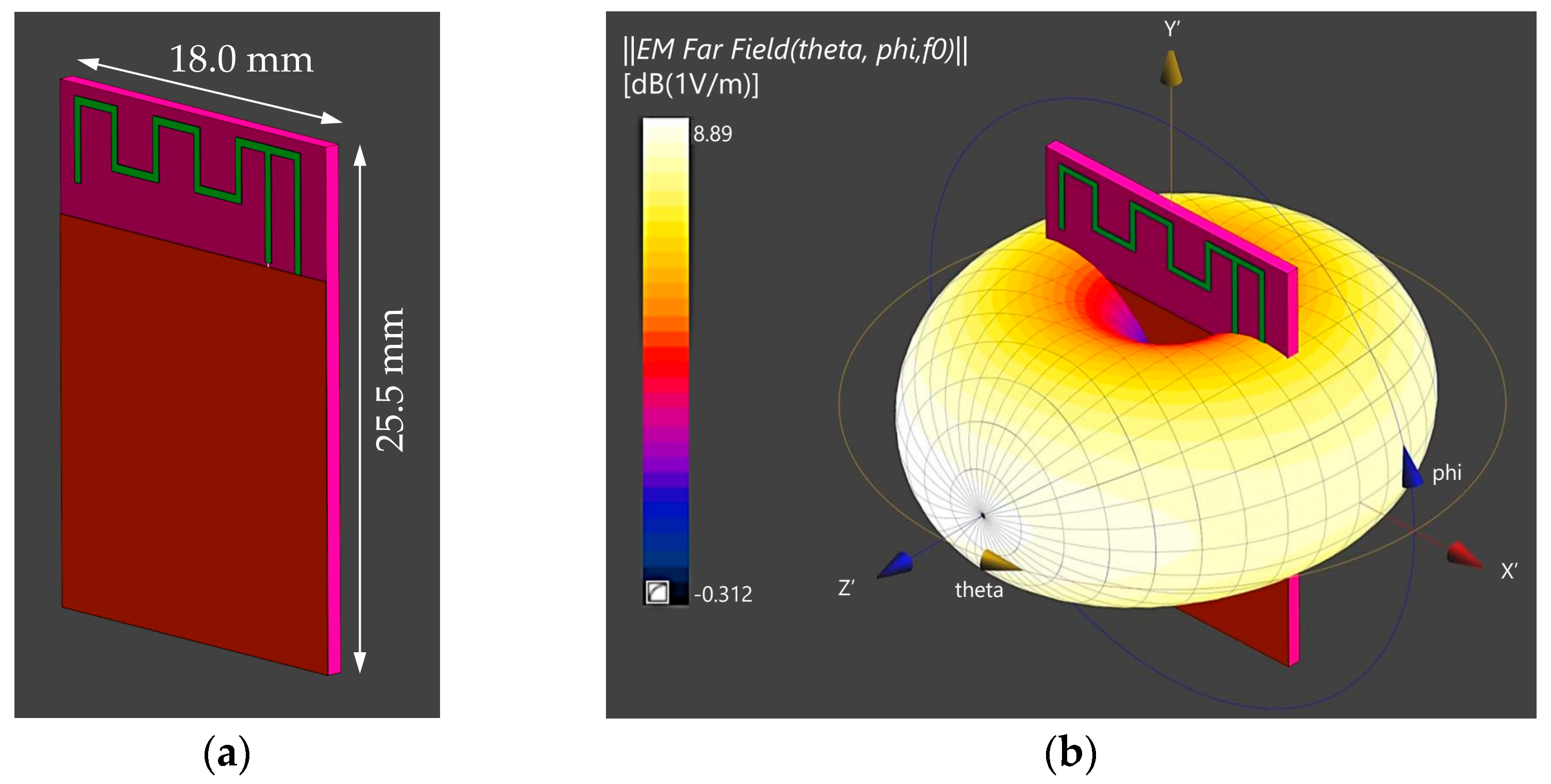
2.3. Numerical Model of Wearable WIT Device

The investigations were conducted for a wearable WIT device capable of establishing Wi-Fi and/or Bluetooth connections in the 2.45 GHz ISM band. A key element of such a device is the RCM (in our case, the commercially available, easily programmable ESP32-WROOM module (Espressif Systems, Shanghai, China)), equipped with a circularly polarized omnidirectional MIFA antenna (meandered inverted-F antenna) [1,6]. This popular RCM has been developed and optimized for free-space operation in the 2.45 GHz ISM band, whereas the capacitive coupling between the body and the antenna changes the resonant frequency and input impedance of the body–antenna complex loading the RCM in considered exposure scenarios [7,20].
The investigations did not include any additional matching circuits or other structures that may optimize the parameters of its EMR emission or minimize SAR for the operation of the RCM near the body [10,18,29]. The numerical model of the considered RCM comprised an MIFA with external dimensions of 15.3 mm × 5.9 mm and a thickness of 0.035 mm with the assigned parameters of copper, placed on a substrate with external dimensions of 18.0 mm × 25.5 mm, a thickness of 0.7 mm, and the parameters of FR-4 (glass-reinforced epoxy laminate material) (Figure 1a, Table 2). Details of the numerical model are reported in [1,6,8]. The numerical model of the investigated antenna in free space at 2.45 GHz frequency is characterized by 1.11 dBi gain, 1.74 dBi directivity, and radiation patterns (3D and 2D), as shown in Figure 1 and Figure 2.

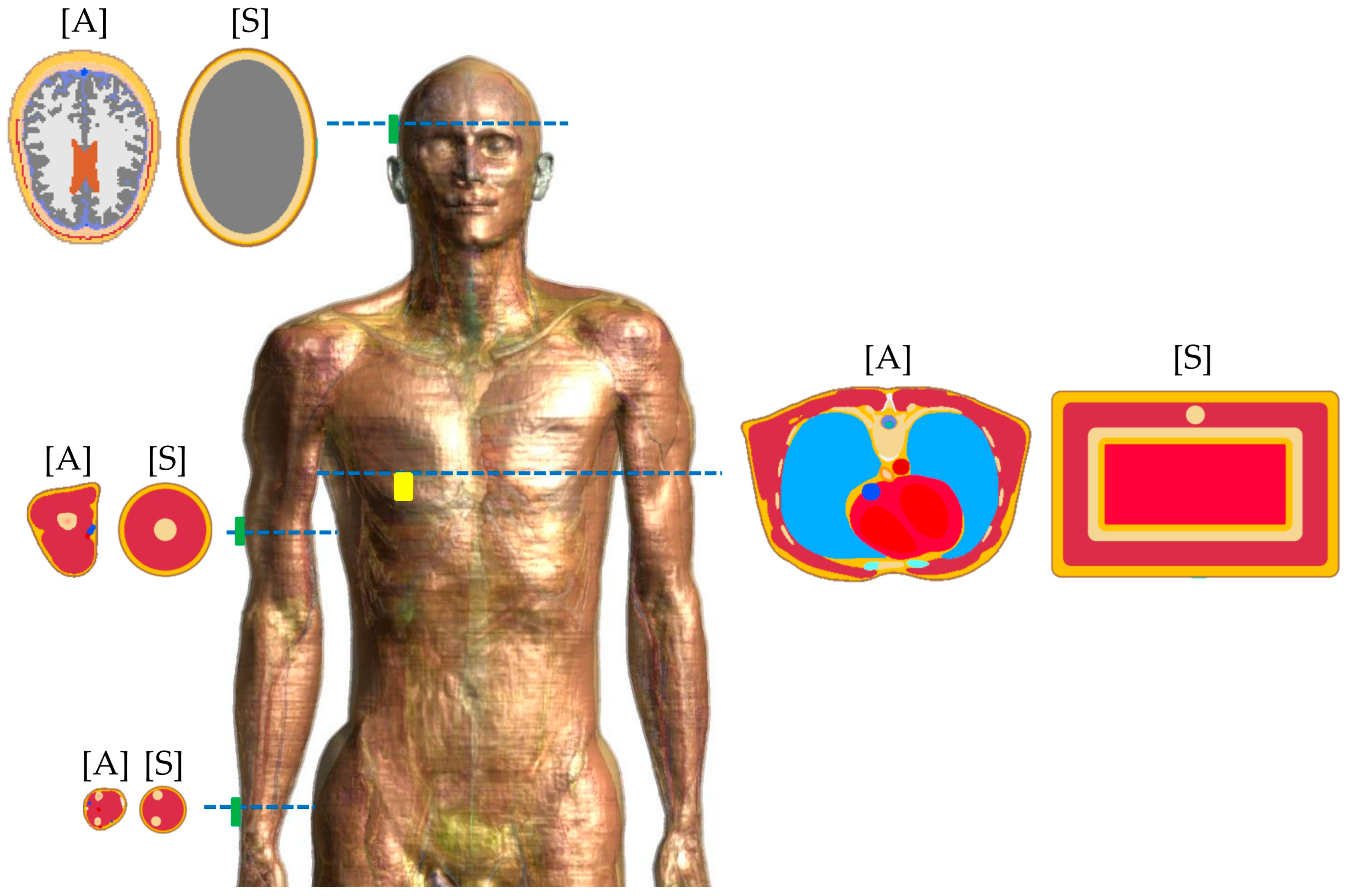
2.4. Numerical Models of the RCM User’s Body and Exposure Scenarios

A fundamental feature of devices designed to be worn on the body is that they may be located near various parts of the body [1,2,3,4,5,6,7,8,9,10,11,12,13,14,15]. Our numerical simulations cover the most common exposure scenarios, employing numerical models of the head, arm, forearm, and chest. The novelty of our approach is in simultaneously using both simplified [S] body sections (multi-layer) and those reflecting the relevant anatomical [A] structure of the human body (by using a model of the whole body with an RCM located near particular body parts corresponding to the considered simplified models of particular body sections), and then comparing the outcome from both approaches in particular exposure scenarios.
The anatomical [A] model used in the study was the commercially licensed Duke v3.1, developed by IT’IS (Foundation for Research on Information Technologies in Society, Zurich, Switzerland) [30]. It consists of over 300 tissues/organs, is 177 cm tall, weighs 70.2 kg, and has a body mass index (BMI) of 22.4. Details of the simplified, multi-layered numerical models developed for this study are presented in Figure 3 and Table 3.
The dimensions of the simplified [S] models of the head, arm, and forearm correspond to the dimensions of the 50th percentile of adult males of the Polish population, and the thicknesses of particular layers correspond to the medians defined for humans, or to the anatomical [A] model used [31,32]. In turn, the earlier developed simplified [S] numerical model of the chest corresponded to a physical phantom designed for research on WBANs, as presented in [8]. Its dimensions are 320 mm in width and 188 mm in depth, making it comparable to the dimensions of the chest of the anatomical [A] model used (approx. 318 mm in width and 215 mm in depth). The numerical models of the chest are comparable to the dimensions of the 50th percentile of adult males of the Polish population in a standing position (292 mm in width and 242 mm in depth) [31].
The exposure scenarios also covered models from two groups of WIT devices: (1) a model of a device for use in the form of a disposable, adhesive plaster (APD), where the ARCM is located directly on the body (0 mm distance between the ARCM and the body) and (2) a model of a classic, reusable, wearable electronic device mounted inside a plastic housing (CWED), where the ARCM is located 2 mm away from the body surface.

2.5. Numerical Simulations

Numerical simulations of EMR emission parameters (operating parameters of the modeled MIFA) and the related SAR were performed using the commercially licensed software Sim4Life v7.2.4 (Zurich Med Tech, Zurich, Switzerland) based on the finite difference time domain (FDTD) method compliant with relevant standardized requirements [15,16,33]. The standard uncertainty of the simulations was estimated at ±(20–25)%, relevant to the state-of-the-art in this field [1].
The finest resolutions of the numerical models were 0.005 mm for the antenna and 0.5 mm for models of particular body parts (better than 1/15 of the wavelength in tissues at 2.45 GHz, i.e., better than 1 mm), which is the minimum resolution for SAR assessment required by standardization requirements (e.g., IEC 62232:2022) [33].
The simulations’ domain was extended by 200 mm in each direction from the nearest surface of the considered models. The absorption boundary conditions (ABCs) were applied to all of its walls.

3. Results

3.1. Validation of the Numerical Models

The numerical model of the ARCM (in free space) and the numerical models of the exposure scenarios with the ARCM located on or near the forearm, arm, and chest were validated by comparing the S11 parameter (reflection coefficient) frequency characteristics obtained through the simulation with those obtained in laboratory tests using relevant physical models (detailed information on the applied laboratory test methodology is presented in [1,6,8]). The analysis of the obtained results showed relevant agreement between the measurement and the simulation results—the differences did not exceed 3.6% in the resonant (matching) frequency of the ARCM and 4.6% in the S11 parameter at 2.45 GHz (Table 4).

3.2. Results Obtained at 100 mW (20 dBm) Input Power to the ARCM

Table 5 presents the ARCM parameters calculated in exposure scenarios with various models of body parts, at 100 mW (20 dBm) input power to the antenna, 1.0 duty cycle, and 2.45 GHz frequency (resonant frequency, S11 parameter, gain, equivalent isotropically radiated power (eirp)), as well as the associated 10g-SAR (averaged over a 10g cubic mass and equivalent to six minutes averaging because of the 1.0 duty cycle).

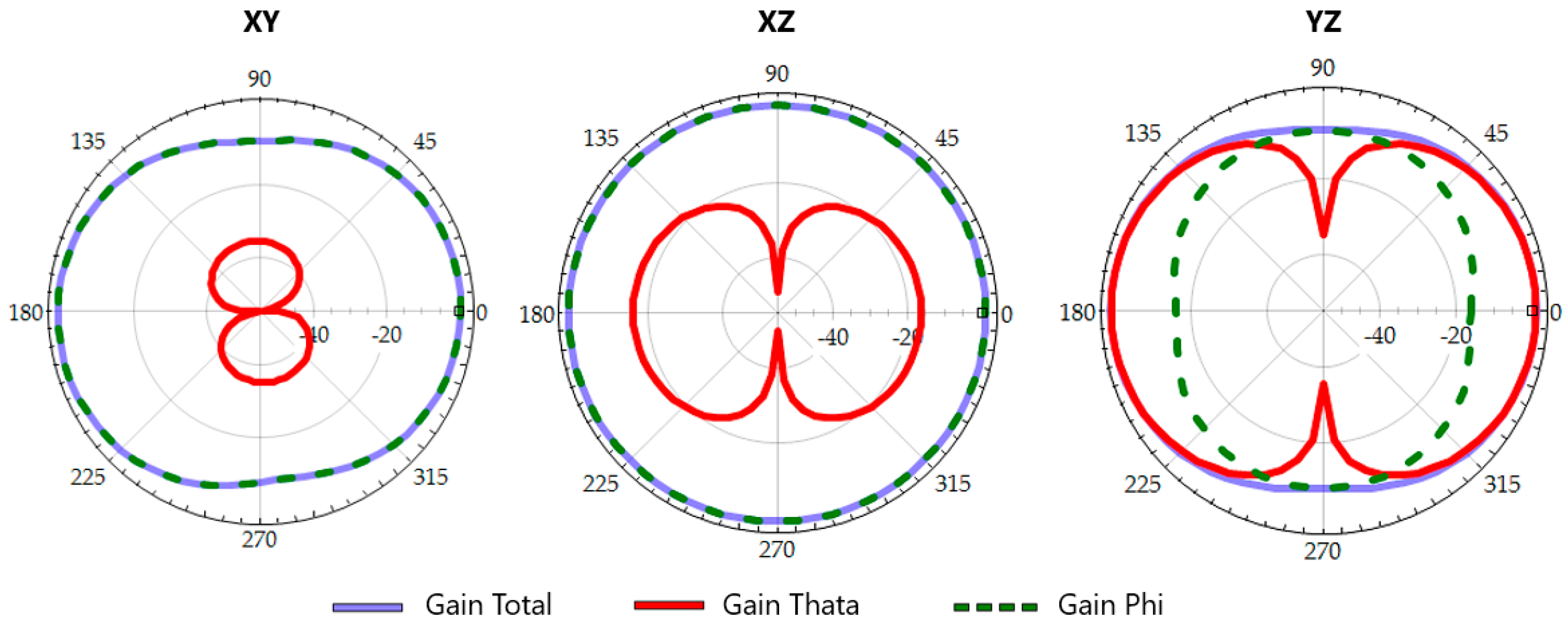
3.2.1. The ARCM Parameters

The proximity of the body to the ARCM may have a significant impact on its performance. In the APD scenarios, mismatches between the obtained resonant frequencies and the nominal operating frequency of 2.45 GHz were observed: lower values in the range from 35% (ARCM on the forearm) to 45% (ARCM on the chest) (Table 5). However, in the CWED scenarios, the resonant frequency mismatches were discovered in the range from 7.8% (ARCM on the arm) to 12% (ARCM on the head) only. In turn, the S11 parameter values at 2.45 GHz varied from −0.561 dB (ARCM on the chest) to −0.992 dB (ARCM on the forearm) and from −3.21 dB (ARCM on the chest) to −4.24 dB (ARCM on the arm) for the APD and CWED exposure scenarios, respectively. These levels of the S11 parameter value result in the antenna input power being (12–20)% and (52–62)% of the output power from the RCM, respectively.
In addition, differences in antenna gain and associated eirp were observed. The antenna gain varied in range from −17.5 dB (ARCM on the head) to −9.44 dB (ARCM on the forearm) for the APD exposure scenarios and from −12.4 dB (ARCM on the chest) to −5.83 dB (ARCM on the forearm) for the CWED scenarios.

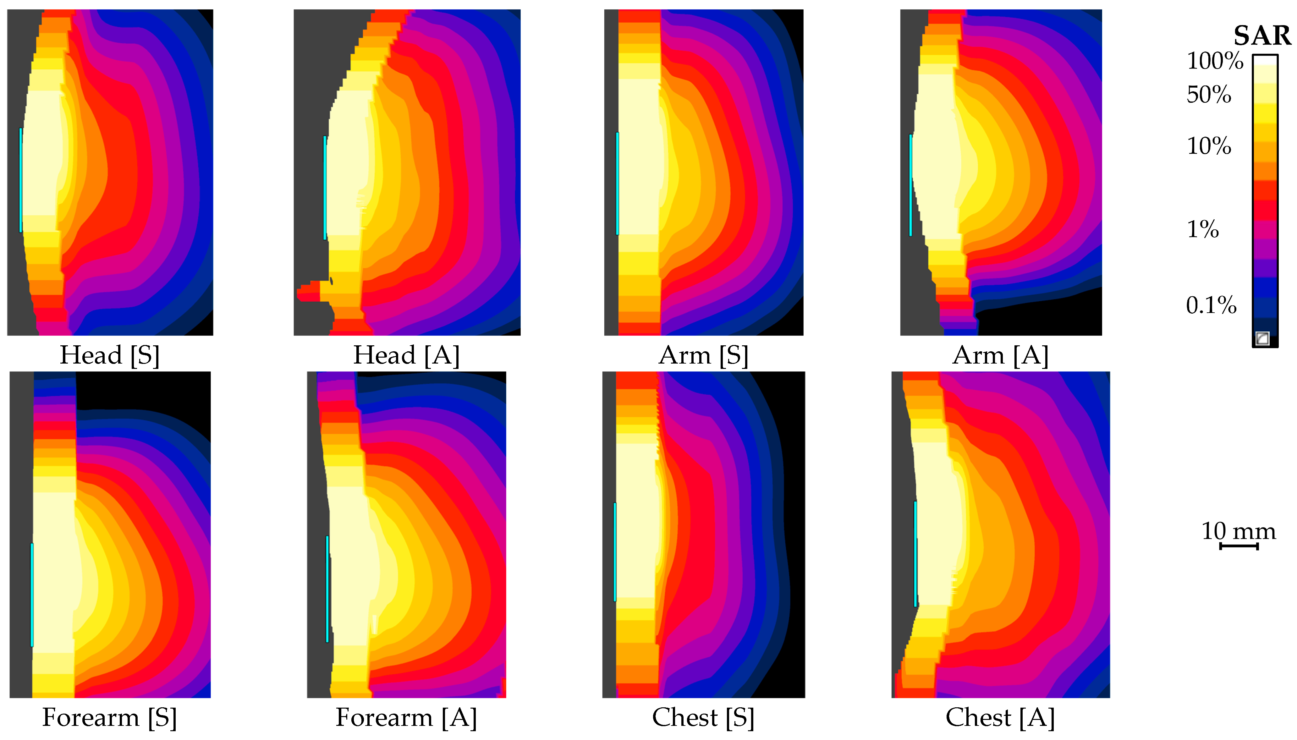
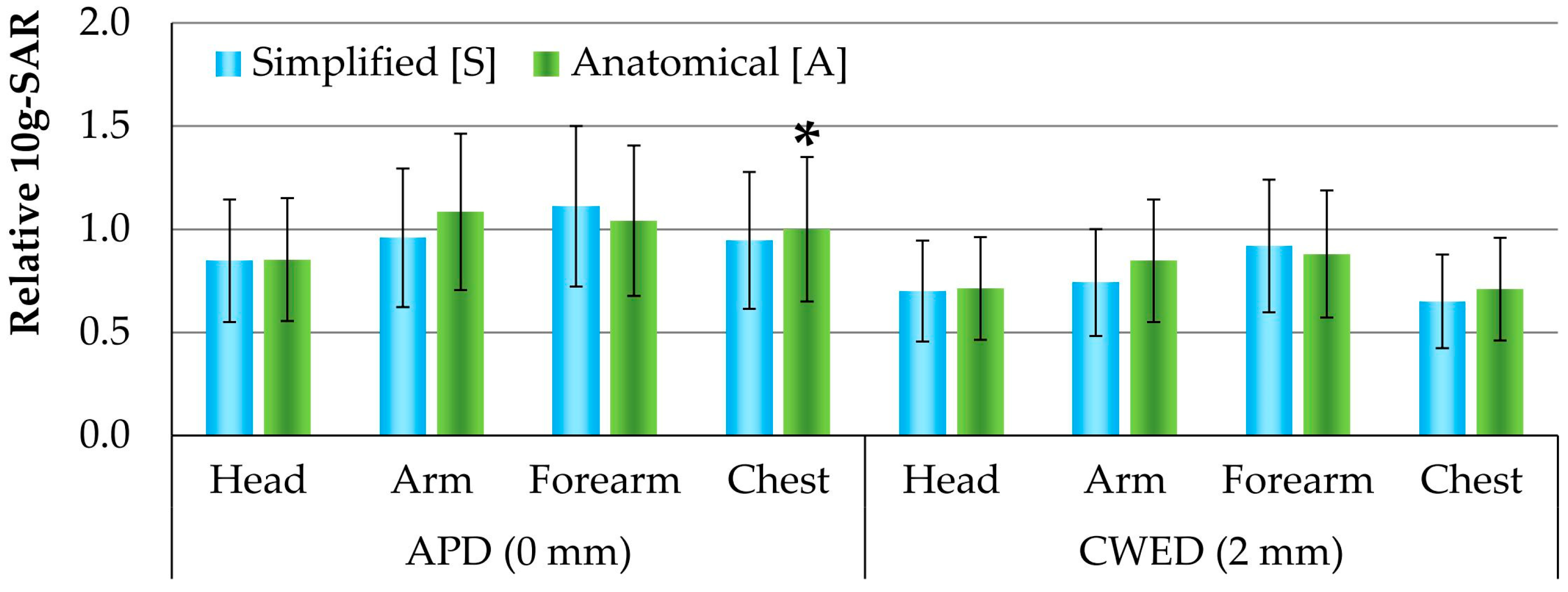
3.2.2. Local 10g-SAR

The maximum local 10g-SAR in the considered exposure scenarios varied from 4.73 W/kg (ARCM on the head) to 6.20 W/kg (ARCM on the forearm) for the APD exposure scenarios and from 3.63 W/kg (ARCM on the chest) to 5.13 W/kg (ARCM on the forearm) for the CWED exposure scenarios (Table 5). The 10g-SAR spatial distributions in various exposure scenarios are presented in Figure 4.

4. Discussion

The influence of the various locations of a wearable ARCM near the body on the parameters of EMR emissions (antenna parameters) and the related SAR in tissues adjacent to the ARCM was analyzed. All the parameters were analyzed as relative values (according to the relationship X/XAPD-chest[A], where X—the value of a particular parameter, XAPD-chest[A]—the reference value of a particular parameter obtained in the APD exposure scenario with an anatomical [A] model of chest, taking into account their values expressed on a linear scale in order to uniformly analyze the variability of various quantities). The applied reference values from the exposure scenario with an ARCM on the chest were due to the following: (1) the chest model is one of the most commonly used models in such research studies; (2) low gain and S11 values in such cases; and (3) relatively high frequency mismatch and 10g-SAR values in such cases [7,8,10,20,21,29].
Additionally, for each exposure scenario, the 10g-SAR values regarding a fixed eirp emitted from the ARCM were compared with the corresponding values obtained for a fixed input power to the ARCM.

4.1. Analysis Regarding Devices Working with a Fixed Input Power to ARCM

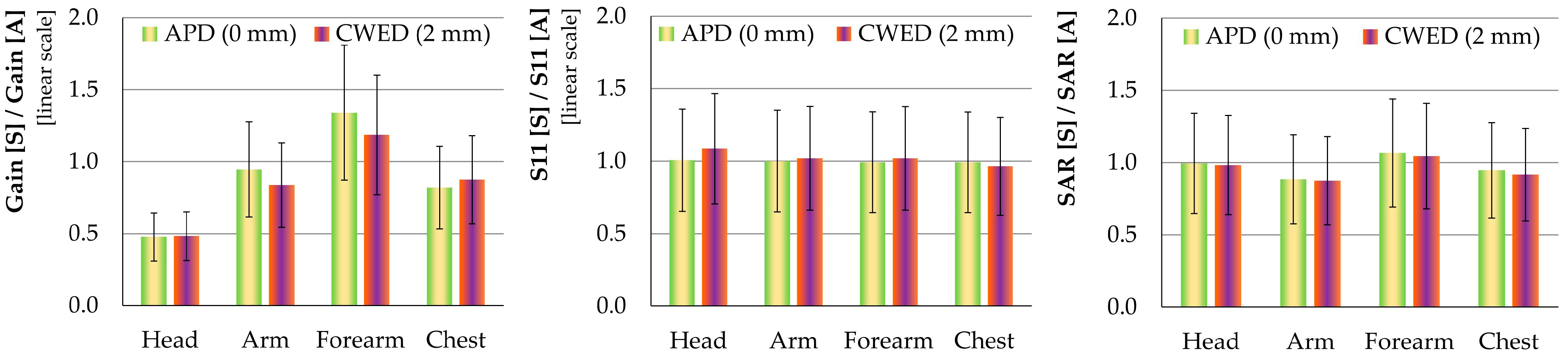
4.1.1. ARCM Parameters

The obtained simulation results show differences of up to 5 times in antenna gain and up to 5% in S11 parameter values within all the APD exposure scenarios, normalized to the anatomical [A] chest case (linear scale), as shown in Figure 5. In the case of the CWED exposure scenarios, differences in values of up to 11 times and 35%, respectively, were found.
The above variability in antenna parameters was observed because the human body acts as part of the antenna when the antenna is located very close to the body—as reported in many studies [7,20]. In particular, the antenna gain and the S11 parameter are among the key parameters regarding various functionalities of the wearable WIT device equipped with an ARCM, e.g., battery life and operating range or data rate, as well as eirp and electromagnetic impact on the user (SAR) [6,34]. The observed increase (up to 2 times) in the gain values and decrease (up to 30%) in S11 in the CWED exposure scenarios compared to APD result in increased device functionality and reduced SAR.

4.1.2. Local 10g-SAR

The obtained 10g-SAR values displayed much smaller differences than the antenna gain, as shown in Figure 6. Up to 15% and 35% differences in the 10g-SAR values (normalized to the APD exposure scenario with the anatomical [A] chest case) within all exposure scenarios were found for the APD and CWED exposure scenarios, respectively.
The obtained 10g-SAR value in the simplified [S] model of the chest in CWED (ARCM 2 mm away from the body) exposure scenario was 5.70 W/kg, which corresponds to the value reported by Ashyap et al., who obtained values of 5.41 and 5.07 W/kg for exposure scenarios with antennas located 1 mm and 3 mm from the body, respectively [7]. Similarly, the 10g-SAR value in the case of the CWED scenario with the simplified [S] model of an arm (5.35 W/kg) also corresponds to values reported by Shah et al. (5.51 W/kg) [11]. In addition, the observed distribution of 10g-SAR values in exposure scenarios with the forearm, arm, and chest models is consistent with the results reported by Wang et al. (the absolute values from their studies cannot be directly compared with our results, due to different distances between the antenna and the human body: i.e., 0 mm or 2 mm in our study, vs. 0 mm or 5 mm) [10].
The differences in the 10g-SAR values obtained for exposure scenarios using various ARCM locations on (APD) or near (CWED) the body were found to be within the standard uncertainty of their determination (±(20–25)%). This suggests that compliance with the SAR limits obtained for the ARCM at any considered locations may also be considered representative for all of the locations covered by this study.

4.1.3. Anatomical Versus Simplified Body Models

Models of the human body constitute a key element of numerical simulations concerning the direct biophysical effects of human EMR exposure. International regulations and standards are vague on this matter. For example, the IEC/IEEE 62704-1:2017 standard allows the use of both high-resolution or simplified [S] human body models, specifying the need to use models representative of the target population with respect to age class, body height, and mass, with appropriate dielectric parameters of tissues and the resolution of models. No reference body models have been published so far. Therefore, in practice, models of the body or its parts from these categories are used in research [7,10,11,18,20,21].
The minor relative difference in the parameters obtained in exposure scenarios with simplified [S] body models compared to the values in scenarios with anatomical [A] models (both APD and CWED exposure scenarios) is smaller than the standard uncertainty of their determination (±(30–35)%), as shown in Table 5 and Figure 7: up to ±12% in 10g-SAR; up to ±18% in gain (except for exposure scenarios with the head, where it was up to 52%); and up to ±9% in S11 parameter values. This indicates that when input power to the antenna is equal in the considered exposure scenarios, the use of simplified [S] models of the human body (numerical or physical) may be sufficient in order to analyze antenna performance and SAR in the body of a person using a wearable WIT device.
However, we draw attention to the fact that the greatest observed variability in antenna gain values was obtained for the case of anatomical [A] models of a body part with a complex, irregular structure and its simplified counterpart (in head models, where the relative difference can reach up to 52%). This variability may lead to incorrect conclusions about optimizing a wearable WIT device’s functionality and intended use, if these conclusions are based solely on simulation results using simplified [S] models. This is especially important when the ARCM is located at a distance of less than a few millimeters from the user’s body.

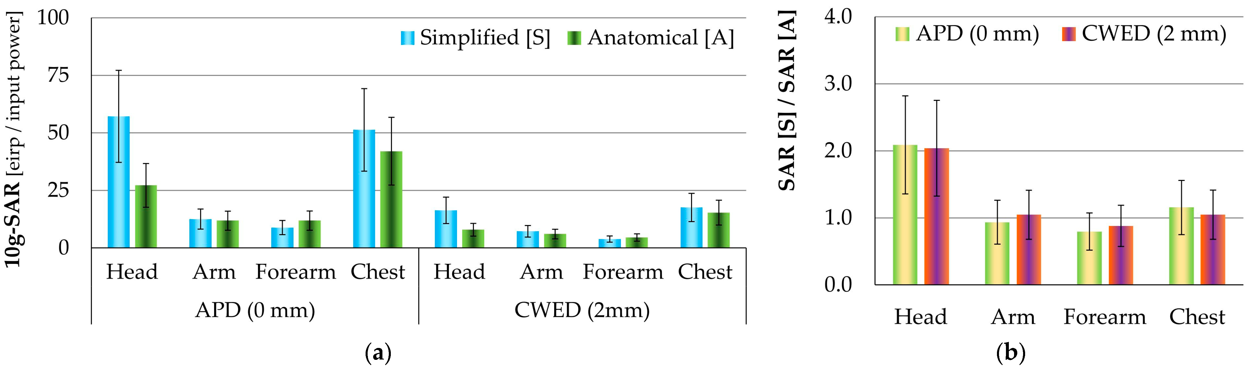
4.2. Analysis Regarding Devices Working with a Fixed Eirp from the ARCM

The ETSI EN 300 328 V2.2.2 (2019-07) is a harmonized standard with a directive 2014/53/EU (known as the RED Directive) for data transmission equipment operating in the 2.45 GHz ISM band [22,23]. According to this standard, the use of such devices is permitted without special administrative permission (e.g., in Poland, issued by the Office of Electronic Communications (UKE)), as long as the eirp emitted from the antenna does not exceed 100 mW (Wi-Fi 2G, Bluetooth class 1) [22,23]. Due to the regulations and the antenna gain variation shown in Figure 5 (up to 5 times variability between cases with fixed eirp from ARCM) among the considered exposure scenarios, it is important to analyze the levels of biophysical effects of EMR on the human body (characterized by 10g-SAR in the user’s body), also in terms of the eirp level. Figure 8 shows the relative differences between the 10g-SAR values obtained at the fixed eirp emitted from a normalized ARCM and values obtained with fixed input power to the ARCM for the considered exposure scenarios.
Up to 58 and up to 18 times higher 10g-SAR values were found in the APD and CWED exposure scenarios, respectively, when the results were based on a fixed eirp level from the ARCM. These values are significantly higher compared to those obtained in exposure scenarios with fixed input power to the ARCM. It can be concluded that at a particular level of eirp from the ARCM, compliance with the SAR limits should be demonstrated on a case-by-case basis. Furthermore, the relative difference in the 10g-SAR values in exposure scenarios with anatomical [A] models compared to simplified [S] ones does not exceed ±20% and ±12% for the APD and CWED exposure scenarios, respectively. These variations were found to be within the standard uncertainty of their determination (±(30–35)%). The exceptions are the 110% lower 10g-SAR values found in exposure scenarios with the simplified [S] model of a head compared to the anatomical [A] model of a head, resulting from the large variability in antenna gain values. This suggests a possible overestimation of 10g-SAR values in simplified [S] models of body parts with a very diverse internal structure in exposure scenarios, when the EMR source is located at a distance of less than a few millimeters from the body. This overestimation leads to a possibly more conservative evaluation of electromagnetic impact on the user of wearable devices when using simplified [S] models, which is usually welcome in safety studies.

4.3. Compliance Assessment with SAR Limits

The numerical simulations evaluated the electromagnetic hazards related to the use of wearables equipped in WIT devices in exposure scenarios with an ARCM operating with a 1.0 duty cycle at 2.45 GHz. The 10g-SAR occupational exposure (in restricted environments) limits in the head and torso (10 W/kg) and the limits in limbs (20 W/kg) were applied. It was shown that in the considered APD exposure scenarios, the effects of EMR on the human body may exceed the 10g-SAR occupational exposure limits at an input power to the antenna exceeding 190 mW (or exceeding 3.7 mW eirp) and 330 mW (or exceeding 28 mW eirp), respectively [17,28]. However, in the case of CWED exposure scenarios, these limits may be exceeded at an input power to the antenna greater than 255 mW (or exceeding 16 mW eirp) and 420 mW (or exceeding 70 mW eirp), respectively.
In turn, the 10g-SAR limits for the general public (in unrestricted environments), i.e., one-fifth of the limits for occupational exposure, may be exceeded at an input power to the antenna that is more than one-fifth of what is specified above for occupational exposure [17,28].
This is particularly important due to the fact that the use of data transmission equipment operating in the 2.45 GHz ISM band (such as Wi-Fi 2G/Bluetooth) at these levels (not exceeding 100 mW eirp) does not require special administrative permission. Results from our study confirmed that such devices are unlikely to cause exposure exceeding SAR limits. Additional attention is needed in connection with the commercial availability of devices emitting at an eirp reaching up to 300 mW, the use of which may cause exposure exceeding discussed limits in the worst-case exposure scenario.

4.4. Duty Cycle

As the local 10g-SAR compliance assessment with the BRs and DRLs refers to the maximum values averaged over a period of any six minutes, one of the key parameters of the WIT system is the duty cycle of EMR emissions. This is defined as the fraction of a period in which a system is active and corresponds to the emitted power averaged over time. Typical values of the duty cycle in Wi-Fi 2G/Bluetooth applications ranged from 0.02 (2%) to 0.95 (95%) and depended on the protocol/standard used for data transmission in packets, the data transmission rate, and the type of transmission (such as file or voice transfer, music or video streaming, etc.) [34]. SAR values are proportional to the time-averaged power of the affecting EMR and therefore to the duty cycle. For example, in particular applications, they will be 50 times, 4 times, and 5% lower than the values discussed in this study (obtained for continuous EMR, with a duty cycle of 1.0), for data transmissions with duty cycles of 0.02, 0.25, and 0.95 respectively.

5. Conclusions

The paper concerns research on how different positions of the ARCM of a wearable WIT device near the body (near the head, arm, forearm, and chest) affect the parameters of the EMR emissions (antenna operating parameters) and the related SAR in a body adjacent to the ARCM, caused by the absorption of EMR emitted from the antenna. The results are discussed using models and exposure scenarios relevant to a wearable device worn on or near the body, operating with a 2.45 GHz ISM band antenna (i.e., 2.400–2.483 GHz band used, for example, in Wi-Fi 2G and Bluetooth applications).
Regarding devices compared at a fixed antenna input power, it was shown that in the considered APD and CWED exposure scenarios, the 10g-SAR compliance demonstrated for the ARCM at any of the considered locations near the body may also confirm compliance for other locations. This is the case, even when compliance is demonstrated using the most simplified [S] models, such as the arm or forearm (the obtained variability in 10g-SAR values did not exceed the standard uncertainty of the applied numerical simulations in such cases). The use of simplified [S] models of human body parts for these purposes has also been shown to be sufficient.
The applicability of simplified [S] models (e.g., multi-layer) allows for the development of twin physical phantoms on the basis of the considered numerical models. These can then be easily used in experimental studies (e.g., regarding MW imaging and sensing, wireless implantable devices, WBAN, etc.).
Regarding devices compared at a fixed eirp emitted from the antenna: in the considered APD and CWED exposure scenarios, the evaluation and assessment of antenna parameters (especially antenna gain with up to 5 times relative difference in values expressed on a linear scale between the considered exposure scenarios) and 10g-SAR (with up to 5 times relative difference) should be carried out on a case-by-case basis. Otherwise, it may lead to incorrect conclusions regarding the optimization of the functionality of a wearable WIT device design, or to overestimating the 10g-SAR values (conservative evaluation of the electromagnetic impact) in exposure scenarios with an EMR source located up to a few millimeters from the body.
Furthermore, performing such analyses regarding the ARCM positions near body sections of a very complex and irregular structure (e.g., the head) requires the use of anatomical [A] models of a human body.
The analysis of the considered exposure cases and models gives the conclusions mentioned above. However, to gain a deeper understanding of the discussed potential equivalence of using simplified [S] or anatomical [A] body models, future research should explore the use of other body models (especially those of people with significantly different BMIs, i.e., different amounts of subcutaneous fat tissue), other exposure scenarios, ARCMs designed for free space emitting EMR at frequencies other than 2.45 GHz, or other ARCM substrate materials (especially for disposable ARCMs in the form of adhesive patches).

Author Contributions

Conceptualization, P.Z., J.K. and K.G.; methodology, P.Z., J.K. and K.G.; validation, P.Z. and K.G.; formal analysis, P.Z. and J.K.; investigation, P.Z., J.K. and K.G.; resources, K.G.; data curation, P.Z. and K.G.; writing—original draft preparation, P.Z. and J.K.; writing—review and editing, P.Z. and J.K.; visualization, P.Z.; supervision, J.K.; project administration, P.Z. All authors have read and agreed to the published version of the manuscript.

Funding

The results of research funded by the National Centre for Research and Development (Warszawa, Poland), agreement no. DWP/PNiWP/VI/2023, task no.: II.PN.04: Optimization of the Configuration of Selected Industrial Systems Using Radiofrequency Links for Energy or Information Transfer in the Context of Their Interaction with the Human Body (Using ComputerModeling).

Institutional Review Board Statement

Not applicable.

Informed Consent Statement

Not applicable.

Data Availability Statement

The original contributions presented in this study are included in the article. Further inquiries can be directed to the corresponding author.

Conflicts of Interest

The authors declare no conflicts of interest. The funders had no role in the design of the study; in the collection, analyses, or interpretation of data; in the writing of the manuscript; or in the decision to publish the results.

Abbreviations

The following abbreviations are used in this manuscript:
ABCAbsorbing Boundary Conditions
APDAdhesive Plaster Device
ARCMAntenna of Radio Communication Module
BRBasic Restrictions
CWEDClassic Wearable Electronic Device
DRLDosimetric Reference Limit
EirpEquivalent Isotopically Radiated Power
FDTDFinite Difference Time Domain
HSPA+Evolved High-Speed Packet Access
ICNIRPInternational Commission on Non-Ionizing Radiation Protection
IEEEInstitute of Electrical and Electronics Engineers
ISMIndustrial, Scientific, Medical
LTELong-Term Evolution
MIFAMeandered Inverted-F Antenna
NB-IoTNarrow Band Internet of Things
MWMicroWave
RCMRadio Communication Module
RED DirectiveDirective 2014/53/EU
SARSpecific Absorption Rate
SHF RFIDSuper-High-Frequency Radio-Frequency IDentification
UMTSUniversal Mobile Telecommunications System
WBANWireless Body-Area Network
Wi-FiWireless-Fidelity
WITWireless Information Transfer

References

  1. Zradziński, P.; Karpowicz, J.; Gryz, K.; Morzyński, L.; Młyński, R.; Swidziński, A.; Godziszewski, K.; Ramos, V. Modelling the Influence of Electromagnetic Field on the User of a Wearable IoT Device Used in a WSN for Monitoring and Reducing Hazards in the Work Environment. Sensors 2020, 20, 7131. [Google Scholar] [CrossRef] [PubMed]
  2. Zradziński, P.; Karpowicz, J.; Gryz, K.; Owczarek, G.; Ramos, V. Modelling and Evaluation of the Absorption of the 866 MHz Electromagnetic Field in Humans Exposed near to Fixed I-RFID Readers Used in Medical RTLS or to Monitor PPE. Sensors 2021, 21, 4251. [Google Scholar] [CrossRef] [PubMed]
  3. Zradziński, P.; Karpowicz, J.; Gryz, K. Principles of evaluating the electromagnetic aspects of using wearable Internet of Things devices. Princ. Methods Assess. Work. Environ. 2022, 38, 7–38. [Google Scholar] [CrossRef]
  4. Zradziński, P.; Karpowicz, J.; Gryz, K. Evaluation of the electromagnetic circumstances of the use of wearable locators Principles and Methods of Assessing the Working Environment. Princ. Methods Assess. Work. Environ. 2022, 38, 65–78. [Google Scholar] [CrossRef]
  5. Ramos, V.; Suárez, O.J.; Suárez, S.; Febles, V.M.; Aguirre, E.; Zradziński, P.; Rabassa, L.E.; Celaya-Echarri, M.; Marina, P.; Karpowicz, J.; et al. Electromagnetic Assessment of UHF-RFID Devices in Healthcare Environment. Appl. Sci. 2022, 12, 10667. [Google Scholar] [CrossRef]
  6. Zradziński, P.; Karpowicz, J.; Gryz, K. Assessing the Antenna Performance (Radiated Power) and Electromagnetic Impact (SAR) on a User of a Wearable RF Communication Device, Involving Variously Structured Models. IEEE Access 2025, 13, 19257–19265. [Google Scholar] [CrossRef]
  7. Ashyap, A.Y.I.; Abidin, Z.Z.; Dahlan, S.H.; Majid, H.A.; Kamarudin, M.R.; Alomainy, A.; Abd-Alhameed, R.A.; Kosha, J.S.; Noras, J.M. Highly efficient wearable CPW antenna enabled by EBG-FSS structure for medical body area network applications. IEEE Access 2018, 6, 77529–77541. [Google Scholar] [CrossRef]
  8. Joseph, L.; Zradziński, P.; Chezhian, A.S.; Mandal, B.; Mani, M.; Voigt, T.; Karpowicz, J.; Perez, M.; Karlsson, R.L.; Augustine, R. Anthropomorphic Torso Phantoms and Validation of their Physical and Digital Twins for Body-Area Radio-Communication Applications. IEEE Trans. Biomed. Eng. 2025, 72, 1858–1871. [Google Scholar] [CrossRef]
  9. Kim, S.H.; Basir, A.; Avila, R.; Lim, J.; Hong, S.W.; Choe, G.; Shin, J.H.; Hwang, J.H.; Park, S.Y.; Joo, J.; et al. Strain-invariant stretchable radio-frequency electronics. Nature 2024, 629, 1047–1054. [Google Scholar] [CrossRef]
  10. Wang, M.; Yang, Z.; Wu, J.; Bao, J.; Liu, J.; Cai, L.; Dang, T.; Zheng, H.; Li, E. Investigation of SAR reduction using flexible antenna with metamaterial structure in wireless body area network. IEEE Trans. Antennas Propag. 2018, 66, 3076–3086. [Google Scholar] [CrossRef]
  11. Shah, S.M.; Rosman, A.A.; Rashid, M.A.Z.A.; Abidin, Z.Z.; Seman, F.C.; Majid, H.A.; Dahlan, S.H.; Hamzah, S.A.; Katiran, N.; Ponniran, A.; et al. A compact dual-band semi-flexible antenna at 2.45 GHz and 5.8 GHz for wearable applications. Bull. Electr. Eng. Informat. 2021, 10, 1739–1746. [Google Scholar] [CrossRef]
  12. Krzemiński, J.; Baraniecki, D.; Dominiczak, J.; Wojciechowska, I.; Raczyński, T.; Janczak, D.; Jakubowska, M. Hybrid Printing of Silver-Based Inks for Application in Flexible Printed Sensors. Crystals 2023, 13, 720. [Google Scholar] [CrossRef]
  13. Lepak-Kuc, S.; Kądziela, A.; Staniszewska, M.; Janczak, D.; Jakubowska, M.; Bednarczyk, E.; Murawski, T.; Piłczyńska, K.; Żołek-Tryznowska, Z. Sustainable, cytocompatible and flexible electronics on potato starch-based films. Sci. Rep. 2024, 14, 18838. [Google Scholar] [CrossRef]
  14. Szałapak, J.; Zdanikowski, B.; Kądziela, A.; Lepak-Kuc, S.; Dybowska-Sarapuk, Ł.; Janczak, D.; Raczyński, T.; Jakubowska, M. Carbon-Based Composites with Biodegradable Matrix for Flexible Paper Electronics. Polymers 2024, 16, 686. [Google Scholar] [CrossRef] [PubMed]
  15. Iman, U.R.; Zada, M.; Basir, A.; Hayat, S.; Lim, Y.-H.; Yoo, H. IoT-Enabled Real-Time Health Monitoring via Smart Textile Integration With LoRa Technology Across Diverse Environments. IEEE Trans. Industr. Inform. 2024, 20, 12803–12813. [Google Scholar] [CrossRef]
  16. International Electrotechnical Commission (IEC)/Institute of Electrical and Electronics Engineers (IEEE) 62704-1:2017; Determining the Peak Spatial-Average Specific Ab-Sorption Rate (SAR) in the Human Body from Wireless Communications Devices, 30 MHz to 6 GHz—Part 1: General Requirements for Using the Finite-Difference Time-Domain (FDTD) Method for SAR Calculations. IEC: Geneva, Switzerland, 2017.
  17. International Commission on Non-Ionizing Radiation Protection (ICNIRP). Guidelines for limiting exposure to electro-magnetic fields (100 kHz to 300 GHz). Health Phys. 2020, 118, 483–524. [Google Scholar] [CrossRef]
  18. Hazarika, B.; Basu, B.; Nandi, A. An artificial magnetic conductor-backed monopole antenna to obtain high gain, conformability, and lower specific absorption rate for WBAN applications. Int. J. RF Microw. Comput. Aided Eng. 2020, 30, e22441. [Google Scholar] [CrossRef]
  19. Nguyen, D.; Seo, C. An Ultra-Miniaturized Antenna Using Loading Circuit Method for Medical Implant Applications. IEEE Access 2021, 9, 111890–111898. [Google Scholar] [CrossRef]
  20. Yan, S.; Soh, P.J.; Vandenbosch, G.A.E. Low-Profile Dual-Band Textile Antenna with Artificial Magnetic Conductor Plane. IEEE Trans. Antennas Propag. 2014, 62, 6487–6490. [Google Scholar] [CrossRef]
  21. Casula, G.A.; Montisci, G. A Design Rule to Reduce the Human Body Effect on Wearable PIFA Antennas. Electronics 2019, 8, 244. [Google Scholar] [CrossRef]
  22. Directive 2014/53/EU of the European Parliament and of the Council. Directive 2014/53/EU of the european parliament and of the council of 16 April 2014 on the harmonisation of the laws of the member states relating to the making available on the market of radio equipment and repealing directive 1999/5/EC text with EEA relevance. Off. J. Eur. Union. 2014, L 153, 62–106. [Google Scholar]
  23. European Telecommunications Standards Institute (ETSI) EN 300 328 v2.2.2 (2019-07); Wideband Transmission Systems; Data Transmission Equipment Operating in the 2,4 GHz Band; Harmonised Standard for Access To Radio Spectrum. ETSI: Sophia Antipolis, France, 2019.
  24. European Telecommunications Standards Institute (ETSI) TS 136 101 V18.6.0 (2024-08); LTE; Evolved Universal Terrestrial Radio Access (E-UTRA); User Equipment (UE) Radio Transmission and Reception (3GPP TS 36.101 Version 18.6.0 Release 18). ETSI: Sophia Antipolis, France, 2024.
  25. European Telecommunications Standards Institute (ETSI) TS 125 101 V15.3.0 (2019-05); Universal Mobile Telecommunications System (UMTS); User Equipment (UE) Radio Transmission and Reception (FDD) (3GPP TS 25.101 Version 15.3.0 Release 15). ETSI: Sophia Antipolis, France, 2019.
  26. European Telecommunications Standards Institute (ETSI) EN 300 440 V2.1.1 (2017-03); Short Range Devices (SRD); Radio Equipment to Be Used in the 1 GHz to 40 GHz Frequency Range; Harmonised Standard Covering the Essential Requirements of Article 3.2 of Directive 2014/53/EU. ETSI: Sophia Antipolis, France, 2017.
  27. European Telecommunications Standards Institute (ETSI) TR 103 711 V1.1.1 (2020-10); Smart Body Area Network (SmartBAN); Applying SmartBAN MAC (ETSI TS 103 325) for Various Use-Cases. ETSI: Sophia Antipolis, France, 2020.
  28. Institute of Electrical and Electronics Engineers (IEEE) C95.1-2019; IEEE Standard for Safety Levels With Respect To Human Exposure To Electric, Magnetic, and Electromagnetic Fields, 0 Hz To 300 GHz. IEEE: New York, NY, USA, 2019.
  29. Ahmad, A.; Faisal, F.; Ullah, S.; Choi, D.-Y. Design and SAR Analysis of a Dual Band Wearable Antenna for WLAN Applications. Appl. Sci. 2022, 12, 9218. [Google Scholar] [CrossRef]
  30. Gosselin, M.-C.; Neufeld, E.; Moser, H.; Huber, E.; Farcito, S.; Gerber, L.; Jedensjö, M.; Hilber, I.; Di Gennaro, F.; Lloyd, B.; et al. Development of a new generation of high-resolution anatomical models for medical device evaluation: The Virtual Population 3.0. Phys. Med. Biol. 2014, 59, 5287. [Google Scholar] [CrossRef] [PubMed]
  31. Gedliczka, A. Atlas Miar Czowieka-Dane Do Projektowania I Oceny Ergonomicznej [Atlas of Human Body Measures-Data Sheets for Ergonomic and Evaluation]; Central Institute for Labour Protection: Warsaw, Poland, 2001. [Google Scholar]
  32. Ruan, J.; Prasad, P. The effects of skull thickness variations on human head dynamic impact responses. Stapp. Car Crash J. 2001, 45, 395–414. [Google Scholar] [CrossRef]
  33. International Electrotechnical Commission (IEC) 62232-2022; Determination of RF Field Strength, Power Density and SAR in the Vicinity of Base Stations for the Purpose of Evaluating Human Exposure. IEC: Geneva, Switzerland, 2022.
  34. Joseph, W.; Pareit, D.; Vermeeren, G.; Naudts, D.; Verloock, L.; Martens, L.; Moerman, I. Determination of the duty cycle of WLAN for realistic radio frequency electromagnetic field exposure assessment. Prog. Biophys. Mol. Biol. 2013, 111, 30–36. [Google Scholar] [CrossRef] [PubMed]
Figure 1. A 3D model of the investigated 2.45 GHz ISM band antenna (a) and its 3D radiation pattern (in dB) in free space at 2.45 GHz (b).
Applsci 15 06602 g001
Figure 2. The 2D radiation patterns (antenna gain in dB) of the investigated 2.45 GHz ISM band antenna in free space at 2.45 GHz.
Applsci 15 06602 g002
Figure 3. Transverse cross-sections of the models of body parts at the height of the ARCM location in particular exposure scenarios ([A] cross-sections—anatomical models; [S] cross-sections—simplified, multi-layer models; green box—side view of the ARCM; yellow box—front view of the ARCM).
Applsci 15 06602 g003
Figure 4. The 10g-SAR distributions in the simplified [S] and anatomical [A] models of a user of a wearable WIT device in the APD exposure scenarios, vertical cross-sections in the plane perpendicular to the ARCM, logarithmic scale. (Note: (1) the highest 10g-SAR were found in the skin and subcutaneous fat tissues; (2) green box on the left—a side view of the ARCM); (3) the protruding part of the body on the left side of the Head [A] case belongs to the ear located near WIT.
Applsci 15 06602 g004
Figure 5. The relative values of antenna parameters (gain, S11: linear scale), calculated in the cases of WIT used near the head, arm, forearm, and chest in APD and CWED 2.45 GHz exposure scenarios and 100 mW (20 dB) input power to the ARCM (all values as in Table 5; *—reference case: the APD exposure scenario with anatomical [A] model of chest; relative gain [linear scale] = 100.1(gain[dB]–reference_gain[dB]); relative S11 [linear scale] = 100.05(S11[dB]–reference_S11[dB]); whiskers—standard uncertainty of relative values determination ± 35%).
Applsci 15 06602 g005
Figure 6. The relative maximum local 10g-SAR values calculated in the WIT user models of the head, arm, forearm and chest, in the APD and CWED 2.45 GHz exposure scenarios, at 100 mW (20 dB) input power to the ARCM (all values as in Table 5; *—reference case: the APD exposure scenario with anatomical [A] model of chest; Relative 10g-SAR = 10g-SAR in particular case/10g-SAR in reference case; whiskers—standard uncertainty of relative values determination ± 35%).
Applsci 15 06602 g006
Figure 7. The relative difference between antenna functionality parameters (antenna gain; S11 parameter; and 10g-SAR values) calculated in the WIT user simplified [S] versus anatomical [A] models of the head, arm, forearm, and chest, in the APD and CWED 2.45 GHz exposure scenarios, at 100 mW (20 dB) input power to the ARCM (whiskers—standard uncertainty of relative value determination ± 35%).
Applsci 15 06602 g007
Figure 8. The relative 10g-SAR values (a) in the APD and CWED 2.45 GHz exposure scenarios (reference value: 10g-SAR at 100 mW (20 dB) input power to the ARCM) and the relative differences (b) calculated in the WIT user simplified [S] versus anatomical [A] models of the head, arm, forearm, and chest, at 100 mW (20 dB) eirp (whiskers—standard uncertainty of relative values determination ±35%).
Applsci 15 06602 g008
Table 1. Characteristics of selected WIT systems for the 2.45 GHz ISM 1 band (and adjacent frequency bands) [23,24,25,26,27].
SystemFrequency Band [MHz]Max Eirp 2 [mW]Duty Cycle 3References
Wi-Fi 2G2400–2483.5100 (Class 1)0.02–0.95ETSI EN 300 328 V2.2.2 (2019-07) [23]
LTE; LTE-M; NB-IoT1880–1920; 1920–1980; 2110–2170; 2300–2400; 2496–26901250 (Class 1);
200 (Class 3)
0.02–0.95ETSI TS 136 101 V18.6.0 (2024-08) [24]
UMTS; HSPA+1885–2025; 2110–220020000.02–0.95ETSI TS 125 101 V15.3.0 (2019-05) [25]
Bluetooth (LE); ZigBee2400–2483.5100 (Class 1);
2.5 (Class 2);
1 (Class 3)
ETSI EN 300 328 V2.2.2 (2019-07) [23]
SHF RFID2446–2454500
(4000 in building)
0.01–0.7
(0.01–0.15 in building)
ETSI EN 300 440 V2.1.1 (2017-03) [26]
WBAN2360–2400; 2400–2483.51<0.1ETSI TR 103 711 V1.1.1 (2020-10) [27]
1 2.45 GHz ISM band—the 2.45 GHz (i.e., 2.400–2.483 GHz) ISM (Industrial, Scientific, Medical) frequency band; 2 eirp—equivalent isotropically radiated power; 3 duty cycle—a fraction of one period in which a system is active; this depends on the type of data being transferred, the data rate, and the application; LTE—Long-Term Evolution; NB-IoT—Narrow Band Internet of Things; UMTS—Universal Mobile Telecommunications System; HSPA+—Evolved High-Speed Packet Access; SHF RFID—Super-High-Frequency Radio-Frequency IDentification; WBANs—wireless body-area networks.
Table 2. The dielectric properties of materials and tissues of simplified models of body parts used in investigations [1,6,8,10,29].
Material/Tissueεrσ, S/mDensity, kg/m3
The numerical model of the RCM equipped with MIFA
Copper1.05.8 × 1078930
FR-44.03.8 × 10−31850
The simplified numerical models of body parts
Bone110.391910
Brain431.81040
Fat110.27910
Internal organ552.51060
Muscle532.21090
Skin381.51110
Table 3. Dimensions of the simplified, multi-layer models of body parts, developed for this study.
Part of the BodyOuter Dimensions [mm]Tissue (Thickness [mm])
Head238 × 159 × 190Skin (4); Fat (4); Bone (8); Brain (Inner part)
ArmØ 105 × 340Skin (2); Fat (5); Bone (Ø 25); Muscle (Inner part)
ForearmØ 56(90) × 260Skin (2); Fat (2); Bone (Ø 15); Muscle (Inner part)
Chest320 × 188 × 200Skin (2); Fat (12); Muscle (30); Bone (10); Fat (10);
Internal organ (Inner part); Bone (Ø 22)
Table 4. The ARCM emission parameters obtained from measurement and simulation.
Exposure ScenarioMeasurement (Simulation)
Resonant Frequency [GHz]S11@2.45 GHz [dB]
Free space2.400 (2.432)−6.01 (−5.85)
APD 1 on the arm1.545 (1.602)−0.914 (−0.849)
APD 1 on the forearm1.595 (1.631)−0.865 (−0.926)
CWED 2 on the chest2.210 (2.208)−3.13 (−3.53)
1 APD—an exposure scenario that may be considered as a model of a disposable, adhesive plaster with the RCM located directly on the body (0 mm distance between RCM and body); 2 CWED—an exposure scenario that may be considered as a model of a classic, reusable, wearable electronic device located in a plastic housing where the RCM is 2 mm away from the body surface.
Table 5. The ARCM parameters (resonant frequency, S11 parameter, gain, equivalent isotropically radiated power (eirp)) and associated 10g-SAR calculated in exposure scenarios with various models of body parts (at 100 mW (20 dBm) input power to antenna, 1.0 duty cycle and 2.45 GHz).
ScenarioSimplified [S] (Anatomical [A]) Model of User’s Body
Resonant Frequency [GHz]S11@2.45 GHz [dB]Gain [dB]eirp 1 [dBm]10g-SAR [W/kg]
APD exposure scenario (RCM located directly on the body: 0 mm distance between the RCM and the body)
Head1.537 (1.562)−0.837 (−0.886)−17.5 (−14.3)2.43 (5.66)4.73 (4.76)
Arm1.551 (1.602)−0.847 (−0.849)−11.0 (−10.7)9.02 (9.26)5.35 (6.05)
Forearm1.561 (1.631)−0.992 (−0.926)−9.44 (−10.7)10.6 (9.26)6.20 (5.81)
Chest1.365 (1.359)−0.640 (−0.561)−17.1 (−16.2)2.89 (3.76)5.28 (5.58)
CWED exposure scenario (RCM located 2 mm away from the body surface)
Head2.159 (2.155)−3.25 (−3.95)−12.1 (−8.96)7.87 (11.1)3.91 (3.98)
Arm2.223 (2.260)−4.07 (−4.24)−8.56 (−7.80)11.4 (12.2)4.14 (4.73)
Forearm2.214 (2.243)−3.66 (−3.82)−5.83 (−6.59)14.2(13.4)5.13 (4.91)
Chest2.208 (2.169)−3.53 (−3.21)−12.4 (−11.9)7.56 (8.14)3.63 (3.96)
1 eirp—equivalent isotropically radiated power; bold values—the maximum value in the particular subset; underlined values—the minimum value in the particular subset.
Disclaimer/Publisher’s Note: The statements, opinions and data contained in all publications are solely those of the individual author(s) and contributor(s) and not of MDPI and/or the editor(s). MDPI and/or the editor(s) disclaim responsibility for any injury to people or property resulting from any ideas, methods, instructions or products referred to in the content.

