1. Introduction
The global expansion of 5G networks has intensified the demand for compact, high-performance antenna that operate across the sub-6 GHz 5G New Radio (NR) spectrum [
1]. Unlike ultra-fast millimeter-wave (mmWave) frequencies that exhibit high path loss and a limited range, sub-6 GHz bands balance the data transfer rate with coverage [
2]. The 5G NR Sub-6 GHz spectrum includes both low-band (below 1 GHz) and mid-band (3–6 GHz) frequencies, with the latter being particularly critical in terms of 5G deployment, given the balanced trade-off between capacity and the propagation distance [
3].
Among the various frequencies, the n77, n78, and n79 bands have emerged as the most widely adopted for mid-band 5G applications, offering gigabit-class data transfer rates and broad coverage [
4].
Table 1 provides an overview of these key frequency bands, detailing their frequency ranges and typical applications. These bands serve as the backbone of global 5G connectivity, supporting mobile broadband and Internet of Things (IoT) applications, and other wireless services [
5,
6]. In response to these demands, this study proposes a multi-port coupled antenna that enhances both efficiency and multiple-input multiple-output (MIMO) performance. The form factor remains compact. The antenna can be integrated within the metallic chassis of commercial smartphones.
The design of such antenna systems is challenging given the limited space and the presence of metal housings that often trigger strong electromagnetic coupling among antenna elements. Such interactions degrade isolation, increase the envelope correlation coefficient (ECC), and negatively impact overall MIMO performance [
4,
5,
6]. To address these issues, various antenna topologies such as distributed slot arrays, loop-type elements, and shared aperture configurations have been explored. Although some show promise, many suffer from narrow bandwidths, high ECC values, or low radiation efficiency when implemented into metal frame smartphones [
7,
8].
Moreover, in practice, smartphones often assign different radiation efficiency targets to each antenna port because of layout constraints and the need to avoid user hand blockage. Typical efficiency values range from −4.5 to −10 dB depending on the port location and the proximity thereof to other internal components [
9,
10].
In this paper, we introduce a compact multi-port antenna system for sub-6 GHz operation. This is based on a shared coupling structure integrated with the smartphone metal frame. The development strategy is two-staged. Initially, a four-port configuration is used to assess feasibility, followed by transition to a two-port design optimized in terms of isolation and a reduced ECC. Simulations and measurements confirm that the antenna exhibits wideband matching (voltage standing wave ratio [VSWR] ≤ 3), a high radiation efficiency (>−6 dB), isolation that exceeds −12 dB, and an ECC below 0.2 across the n78 band, validating the applicability thereof for practical smartphone platforms.
3. Antenna Designs and Configurations
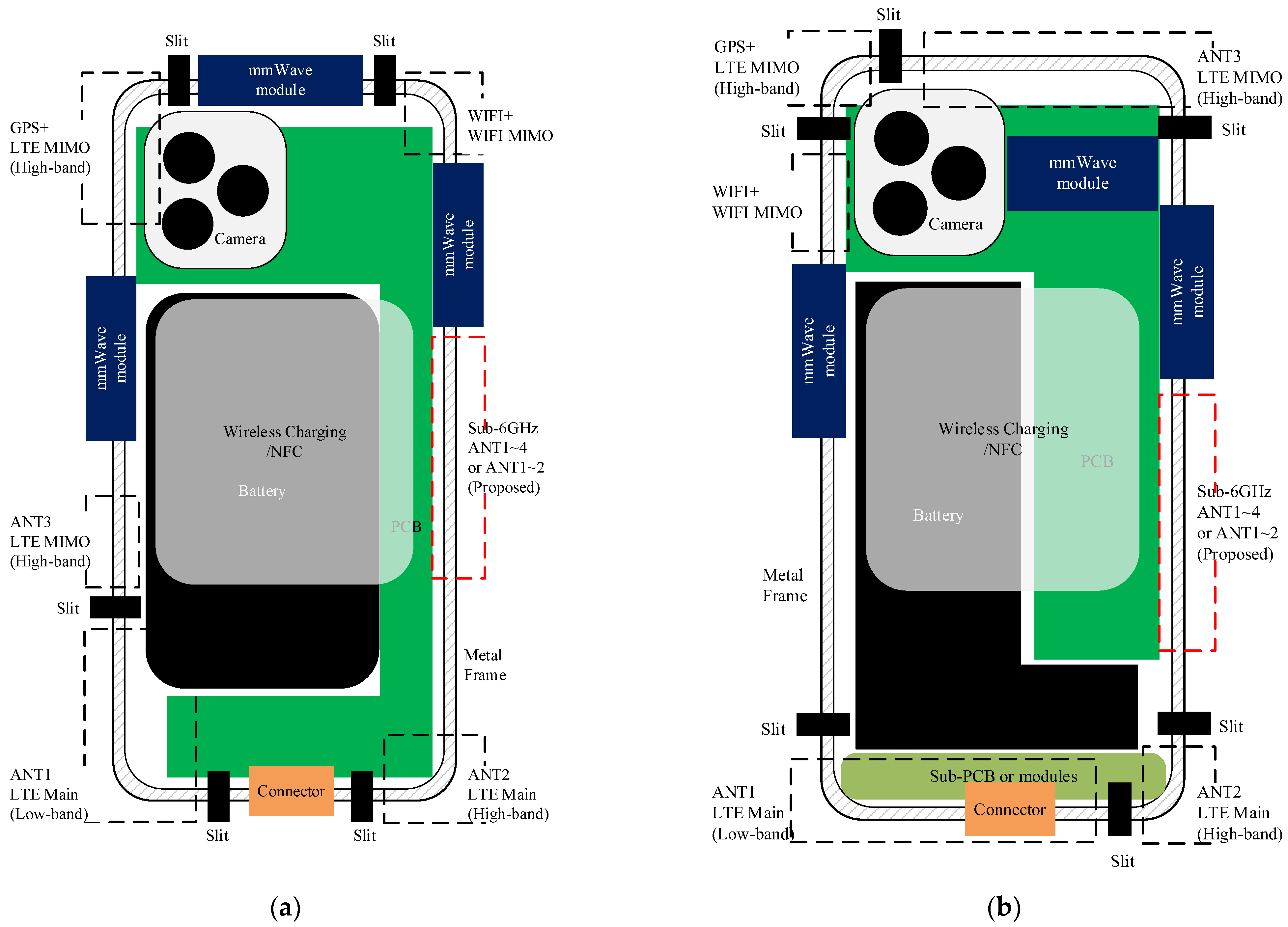
Figure 1 presents the overall antenna layout o, and the mechanical integration strategy for the proposed sub-6 GHz MIMO antenna system within modern smartphone platforms. In commercial smartphones, the internal mechanical architecture, particularly the placement of the PCB and battery, is crucial in terms of determining the space available for antenna integration. Two common configurations are depicted in
Figure 1. In the first [
Figure 1a], the principal PCB is centrally positioned and the battery is in the top of the chassis. This ensures access to the top and sides of the metal frame. Radiofrequency modules and antennas, including sub-6 GHz components, may be installed along the lateral or top edges. However, this limits the ground clearance at the bottom of the device; bottom-mounted antennas cannot be readily placed. The second configuration [
Figure 1b] features a split-level sub-PCB architecture; the PCB is divided and arranged around the battery. This increases the mechanical clearance at the lower edge of the housing, enabling antenna integration beneath the battery or on the sub-PCB. Although this enhances antenna isolation and increases the integration density, it may compromise the placement of high-band or mmWave components at the top of the device. To accommodate both configurations, the proposed sub-6 GHz antenna uses a flexible frame-coupling design that employs the smartphone metal frame as the primary radiator. This enables both lateral-edge and bottom-edge port deployment with maintenance of a consistent impedance and radiation performance across the architectures. When the current paths are shared along the frame and the coupling gap is tuned, the antenna can be placed in various mechanical layouts with minimal structural changes. Such a dual-compatible strategy facilitates seamless integration across diverse smartphone product lines, accelerating the developmental cycles and reducing design complexity.
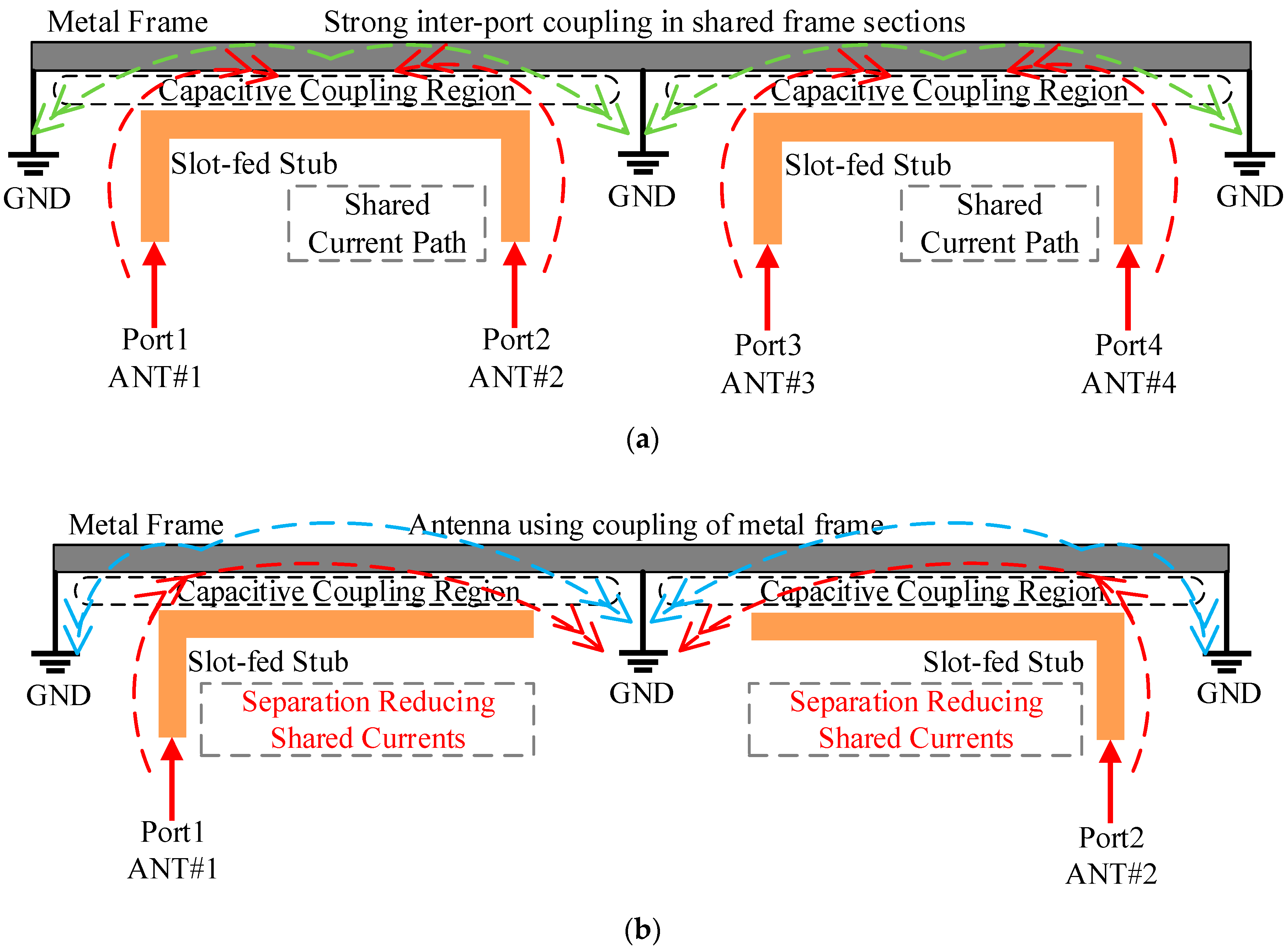
Figure 2 illustrates the conceptual architecture of metal-frame-coupled antennas for sub-6 GHz operation. The design exploits the current distributions and coupling effects along the metal frame. This creates compact multi-port configurations that are spatially very efficient.
Figure 2a shows a four-port configuration. Each side of the metal frame accommodates a shared-coupling antenna. Two symmetrical coupling sections each support two feed ports—ANTs #1 and #2 on the left and ANTs #3 and #4 on the right. The diagram highlights the capacitive coupling regions, the slot-fed stubs, and the shared current paths that extend across the frame sections. This efficiently uses the (limited) edge space of metal framed smartphones, leveraging controlled mutual coupling to enhance pattern diversity and enable (potential) reconfigurability. The strong inter-port coupling in shared frame sections, as depicted, provides additional radiation paths but requires careful impedance tuning. To further explore the simplified configurations and reduce design complexity,
Figure 2b shows a two-port configuration. A single shared coupling antenna is deployed on either side of the frame. Each supports a single feed port (ANTs #1 and #2), thereby simplifying impedance matching and facilitating mechanical integration. In this configuration, the illustration includes Separation Reducing Shared Currents, achieved by grounding separation and spatial decoupling, which effectively suppress shared current paths between the two antennas. This reduces inter-port coupling but retains effective use of the chassis ground and frame current paths. Both configurations exploit the natural resonant characteristics of the metal frame and the distributed ground plane. Radiation is both compact and efficient. There is no need for a protruding structure or a standalone radiator. Moreover, such a shared coupling approach mitigates interference from adjacent components and enhances mechanical robustness, rendering the design well suited for dense smartphone environments. These conceptual topologies form the basis of the final antennas that are integrated into the platform of
Figure 1. The practical performance, including the impedance, isolation, and radiation behaviors, is analyzed in detail in the following sections.
4. Simulation and Optimization
The design process sought to optimize the key performance parameters of impedance matching, gain, and the ECC. The design techniques were tailored for each antenna. Radiation gain was enhanced, and signal interference and inter-element coupling minimized.
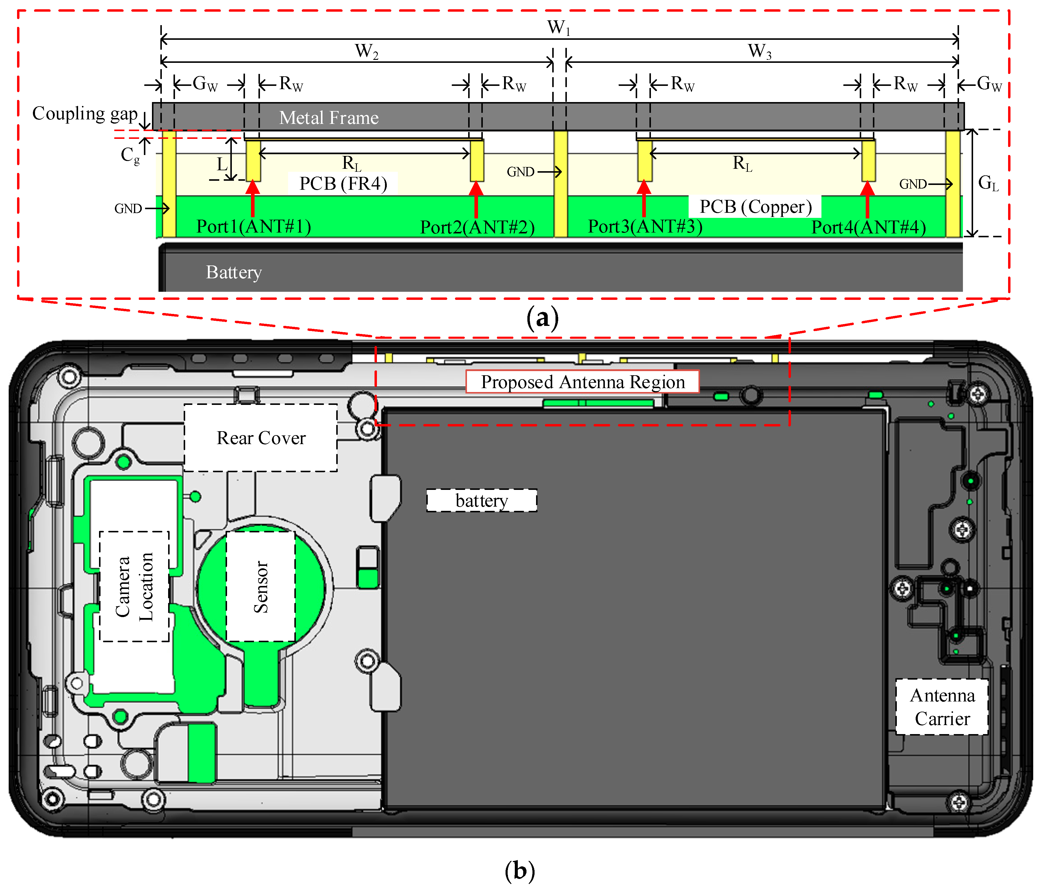
Figure 3 illustrates the mechanical configuration and integration of the multi-port antenna. Metal-frame coupling enables compact integration within a commercial smartphone platform. The design supports four sub-6 GHz MIMO ports but minimizes interference with critical internal components such as the battery and mainboard. As shown in
Figure 3a, the four antenna ports (ANTs #1 to #4) are symmetrically positioned along the inner top edge of the device, creating a shared coupling structure with the metal frame. Several key structural parameters govern the resonant behavior and radiation performance of the antenna. The total antenna width along the top frame is W
1 = 57 mm. W
2 = W
3 = 28 mm; the configuration is geometrically balanced. The coupling gap between the metal frame and the antenna is C
g = 0.6 mm, and both the radiator and ground widths (R
W and G
W) = 1 mm. The antenna coupling length (L) beneath the frame is 3 mm, the radiating length (R
L) along the frame 15 mm, and the grounding length (G
L) at the base 7.6 mm. Each antenna port is a slot-fed stub positioned beneath the frame and is electromagnetically coupled with the edge current. To suppress parasitic coupling and improve inter-port isolation, additional grounding paths and PCB cutouts are incorporated. The entire structure is fabricated on a 0.8 mm thick FR4 substrate, which is a standard commercial grade PCB material.
Figure 3b shows the antenna layout within the smartphone housing (148 × 86 mm). The battery is centrally located. The antenna array is integrated along the top edge within the mechanically reserved region (the red-dotted area). This zone ensures adequate clearance for the coupling length and other critical structural features, enabling effective resonance along the metal frame and robust interaction with the ground plane. The symmetrical arrangement and careful dimensional optimization of the antenna elements enhance both the spatial and polarization diversity, which is particularly useful in edge mounted implementations wherein mutual coupling tends to be more pronounced. The metal frame-integrated design supports compact multi-port operation without the need for an external radiator, thereby offering a highly practical solution when high volume mobile device integration is required.
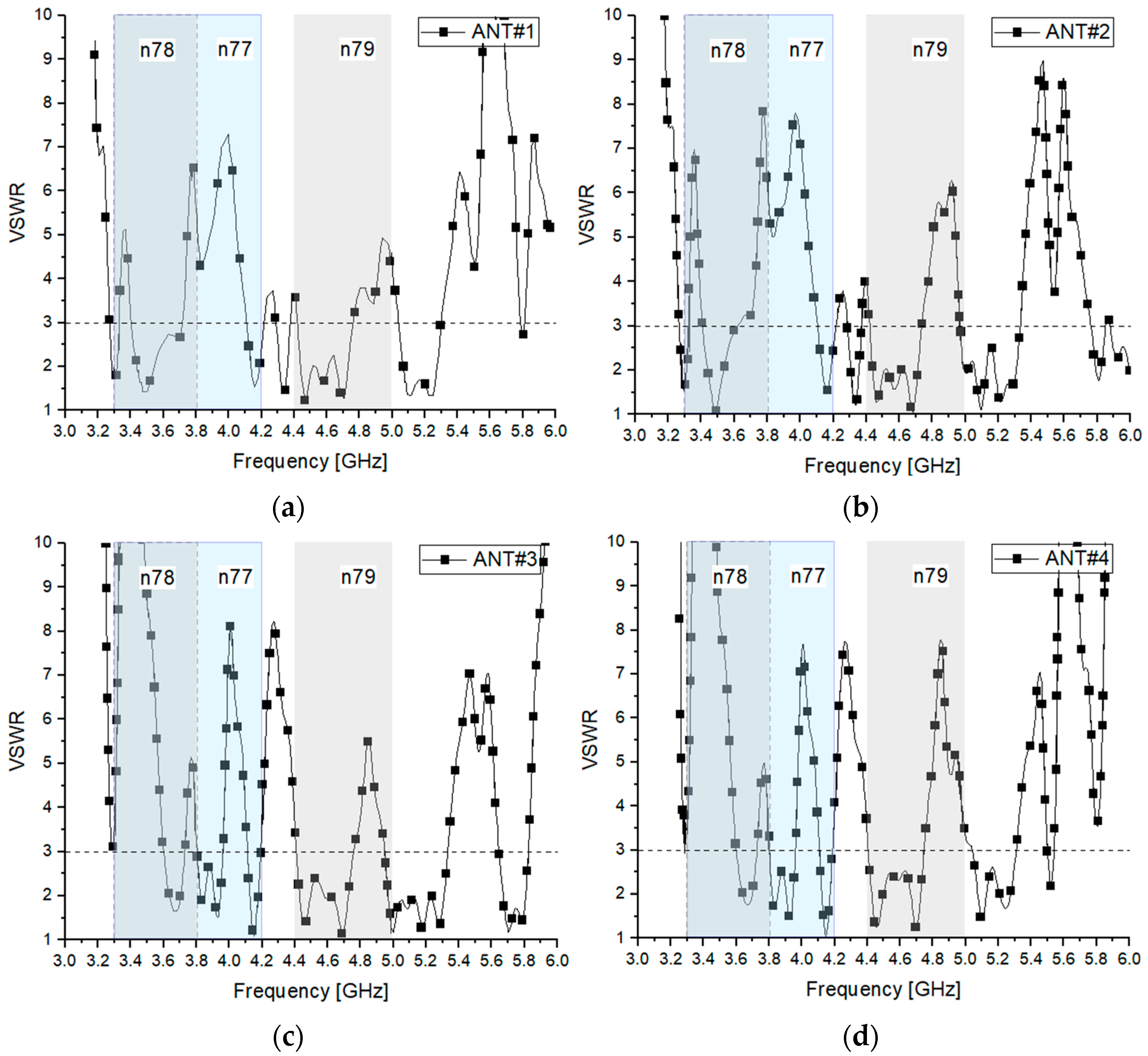
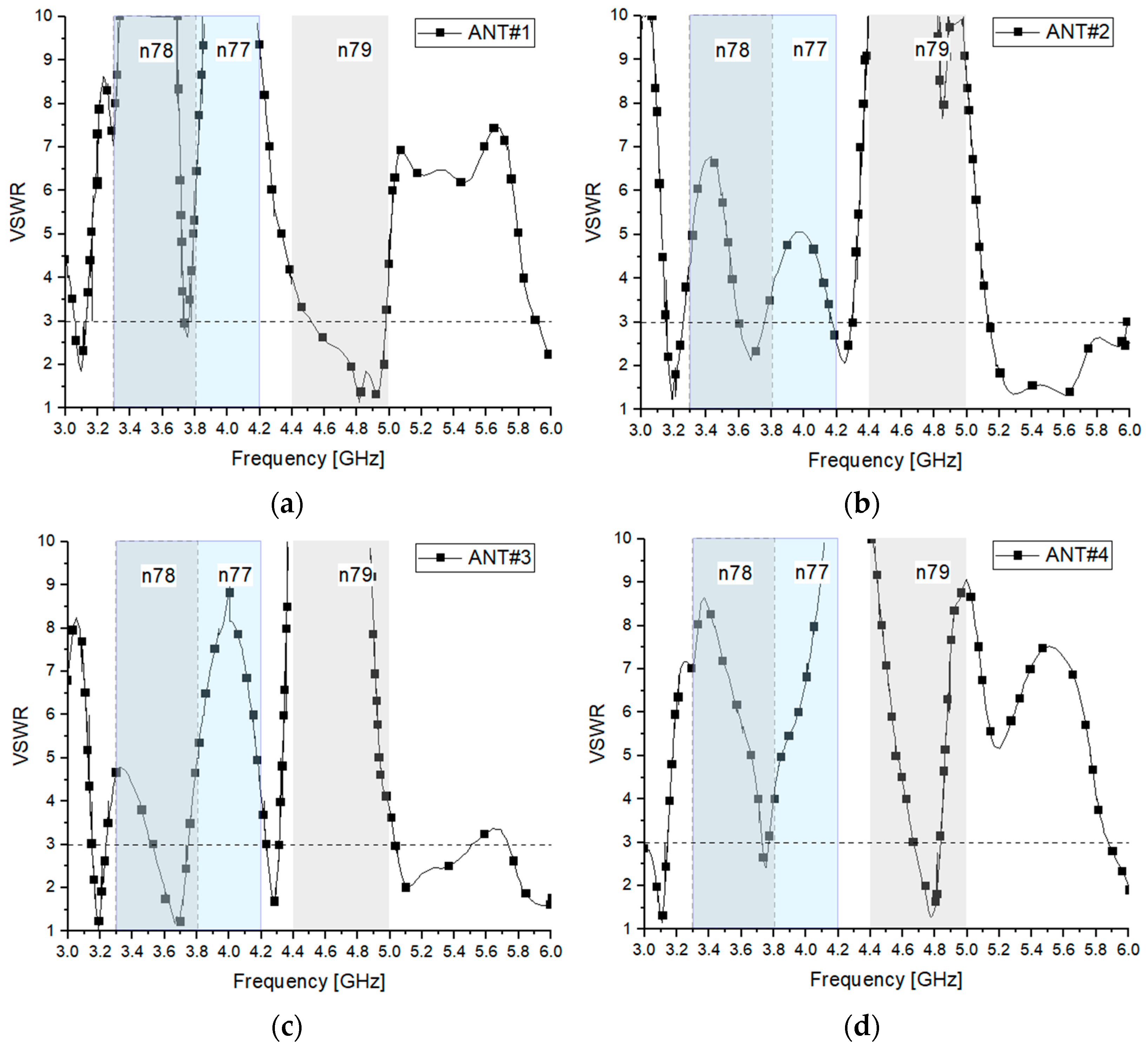
Figure 4 illustrates the simulated VSWR performance of the four-port sub-6 GHz antenna system across three primary 5G NR frequency bands: n78 (3.3–3.8 GHz), n77 (3.3–4.2 GHz) and n79 (4.4–5.0 GHz). The reference VSWR threshold of 3:1 is indicated by dashed lines in each subplot. As shown in
Figure 4a, ANT #1 maintains a VSWR ≤ 3 across the entire n78 band that also partially extends into the n79 band. Impedance matching is good from approximately 3.3 to 4.9 GHz. Similarly,
Figure 4b shows that ANT #2 delivers effective broadband matching over the n77 and n79 bands, with only a slight degradation near 3.6–3.7 GHz within the acceptable limits for sub-6 GHz operation.
Figure 4c,d illustrate the performance of ANTs #3 and #4, respectively, both of which exhibit wideband characteristics spanning the n78 and n79 bands. All four ports exhibit dual resonant behavior attributable to the shared coupling structure and frame-based excitation mechanism. The design ensures a wide impedance bandwidth without a need for discrete external matching components. Overall, the simulations confirm that all four antenna ports exhibit acceptable VSWR characteristics across the required 5G NR bands. The design allows for full 4 × 4 MIMO implementation into compact smartphone platforms. The metal frame coupling technique supports excellent wideband impedance performance across multiple sub-6 GHz bands.
In 5G NR sub-6 GHz systems, particularly within the n78 band (3.3–3.8 GHz), the radiation efficiency of mobile user equipment (UE) antennas plays a pivotal role in terms of overall link performance. Given the inherent integration constraints of compact device platforms, it is common industry practice to allocate distinct radiation efficiency targets to each antenna port. For example, in a typical four-port MIMO configuration, the target efficiencies may be –4.5, –7, –9 and –10 dB, respectively. These values reflect practical trade-offs between antenna positioning, the internal component layout, and the susceptibility to user hand blockage. To assess the system-level impacts of such port-specific efficiency values, a downlink link budget analysis was performed under the following assumptions: a carrier frequency of 3.5 GHz (center of the n78 band), a bandwidth of 100 MHz, a maximum base station effective isotropic radiated power (EIRP) of 57 dBm in line with the 3GPP TR 38.901 standard [
15], and an urban cell edge path loss of approximately 135 dB. The received power at the mobile UE was calculated as
Applying this to each port,
For the port with a −4.5 dB gain,
For the port with a −10 dB gain,
Given a 5G UE receiver sensitivity floor of approximately –98 dBm (assuming 100 MHz of bandwidth and a block error rate [BLER] ≤ 10%), all four antenna ports maintain a positive link margin of at least 10 dB. Even when additional fading and propagation losses are considered, these margins are (generally) sufficient to support robust communication. Furthermore, the inherent MIMO diversity and spatial multiplexing techniques can be used to further alleviate any performance degradation associated with individual port inefficiencies. The radiation efficiency targets adopted here from −4.5 to −10 dB per port are consistent with modern design practice and industry-accepted performance thresholds. The validity of such values was confirmed in previous studies on compact 4 × 4 MIMO antenna systems for the n78 band, where similar or slightly better efficiency levels (e.g., −3 to −6 dB) were reported and deemed acceptable [
7,
9]. In the present study, the target range was based on both a system-level, link budget analysis and the empirical integration constraints, reinforcing the relevance and applicability thereof to real-world smartphone designs.
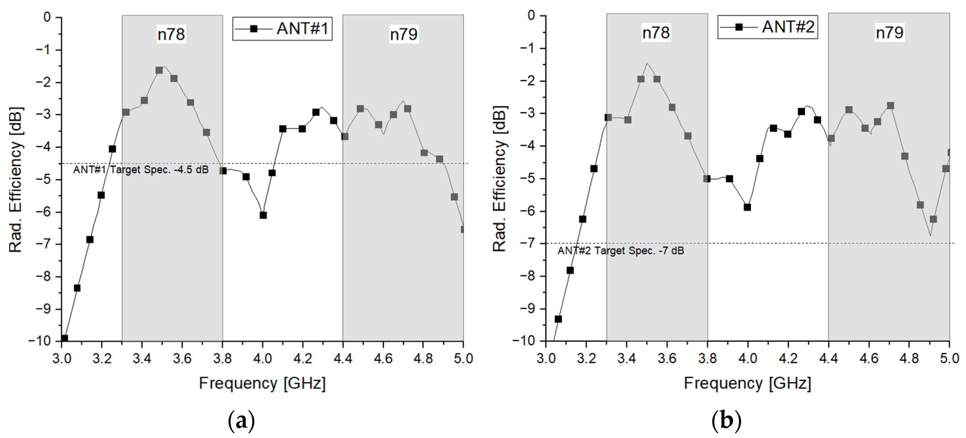
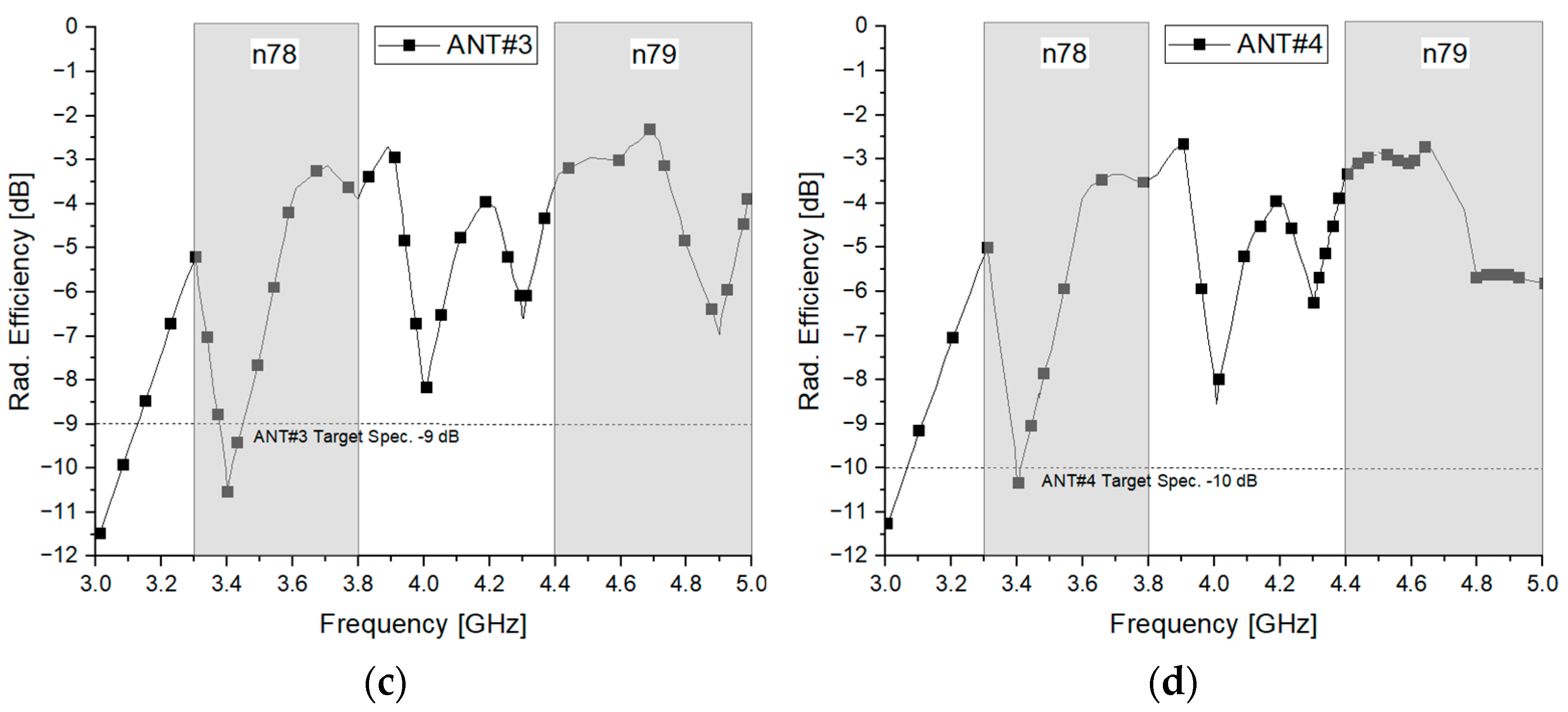
The radiation efficiency performance of each antenna element was next evaluated across the n78 (3.3–3.8 GHz) and n79 (4.4–5.0 GHz) 5G NR bands (
Figure 5). A four-port MIMO configuration was simulated, and the radiation efficiency of each antenna port benchmarked against the respective design target. Specifically, ANT #1 achieved a target efficiency (TE) of −4.5 dB, ANT #2 a TE of –7 dB, ANT #3 a TE of −9 dB, and ANT #4 a TE of −10 dB. These per-port specifications were not arbitrarily chosen, being rather derived from empirical studies and validated using system-level link budget analyses tailored to sub-6 GHz 5G NR terminals. Assuming a base station EIRP of 57 dBm, a cell edge path loss of 135 dB (in an urban scenario), and the above antenna efficiencies, the received power at the UE is estimated to be −82.5 dBm to −88.0 dBm across all four ports. This corresponds to a link margin that exceeds 10 dB relative to the 5G receiver sensitivity threshold of −98 dBm (based on a 100 MHz bandwidth and a BLER ≤ 10%) [
15], thereby ensuring reliable communication even under multipath fading conditions. Moreover, the spatial diversity and multiplexing capabilities inherent in 4 × 4 MIMO systems further reduce the impact of individual port inefficiencies. Comparable efficiency margins have recently been reported and validated in studies on compact sub-6 GHz MIMO antennas for mobile platforms [
1], reinforcing the soundness of the efficiency targets adopted in the present work. In brief, the proposed specifications are grounded in terms of both theory and practical implementation.
5. Feasibility and Measurement
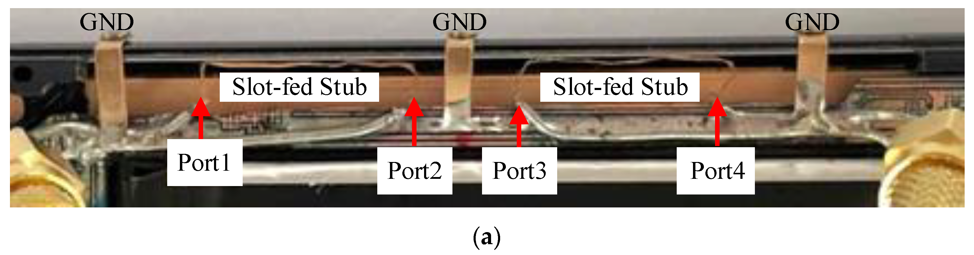
To validate the new antenna design under realistic hardware conditions, a prototype was fabricated and integrated into a commercial smartphone chassis (
Figure 6). The antenna structure was placed along the upper section of the metal frame using a shared-coupling configuration. Four feeding ports (Ports 1–4) were symmetrically distributed. The top view image of
Figure 6a shows the detailed layout, including three intermediate ground taps strategically positioned between the feed points to confine the current distribution along the frame and enhance structural stability. Each port is connected via soldered, coaxial feed lines to surface-mounted SubMiniature version A (SMA) connectors routed through the rear of the device to enable direct interfacing with a VNA that made S-parameter measurements. The complete assembled testbed is shown in
Figure 6b. All ports are actively connected to facilitate simultaneous evaluation of VSWR, isolation, and the ECC. The measurement configuration closely replicates real-world smartphone integration. The internal components include a battery, shielding structures and a realistic PCB. The setup therefore enables practical assessment of factors that affect performance. These include detuning, coupling artifacts, and mechanical constraints. Such elements are often idealized or overlooked during simulations. The results presented in the figures below show that slight frequency shifts and deviations in performance underscore the need for layout optimization and physical prototyping during the final stages of antenna development.
The prototype was fabricated on an FR4 substrate with a nominal thickness of 0.8 mm (±0.05 mm tolerance), a relative permittivity of 4.3 ± 0.2, and a loss tangent of 0.025 ± 0.003. For the conductor layers, adhesive copper tape with a thickness of 35 μm (1 oz equivalent) and an average surface roughness of approximately 2 μm RMS (root mean square) was applied. The feed network was implemented as a 50 Ω microstrip line measuring 1.5 mm in width and 3 mm in length, which transitions to a slot-fed stub with dimensions of 17 mm × 3 mm positioned 0.6 mm beneath the edge of the metal frame. For the measurements, standard SMA connectors (Amphenol 135101-R1) were employed. The vector network analyzer (Keysight E5071C) calibration was performed up to the SMA connector reference plane using a two-port SOLT (Short-Open-Load-Thru) procedure without any additional de-embedding of the connector assembly.
Figure 4 and
Figure 7, respectively, show the simulated and measured VSWR characteristics of the sub-6 GHz multi-port antenna system. The simulations predict good broadband impedance matching (VSWR ≤ 3) across the n78 (3.3–3.8 GHz), n77 (3.3–4.2 GHz), and n79 (4.4–5.0 GHz) bands for all four antenna ports (ANT #1–ANT #4). Dual resonant responses are observed, enabled by the optimized metal frame coupling and slot geometry. The resonance peaks are strategically positioned around 3.4–3.6 and 4.7–4.9 GHz.
Figure 7 shows the measured VSWR when the antenna is implemented in a realistic smartphone (
Figure 6). Although the overall impedance behavior is consistent with the simulations, notable frequency shifts are observed at all antenna ports. In particular, the resonance frequencies of ANTs #1 and #4 are downshifted by more than 200 MHz. ANTs #2 and #3 exhibit shifts of approximately 100 MHz. Sometimes, these deviations trigger partial misalignment with the target n78 band. The discrepancies reflect challenges associated with real-world integration including the PCB tolerances, parasitic SMA effects, and complex internal coupling. Unlike (idealized) simulation conditions, real-world integration introduces detuning effects because of the mutual proximity of internal components (e.g., the battery, shielding, and flexible interconnects), the non-uniform ground return paths, and changes in the surface current distribution along the metal frame. Such findings underscore the need to optimize the electromagnetic design via detailed mechanical and layout aware modeling. This is essential to ensure the consistent performance of real-world smartphones.
Although the shared coupling multi-port structure is both compact and integration-friendly, it is inherently associated with suboptimal isolation and an elevated ECC associated with strong inter-port coupling. To address these limitations, a two-step optimization strategy was implemented as illustrated in
Figure 8.
In Step (a), the original four-port configuration was decomposed into two physically separated two-port antenna modules. Each module was then independently optimized to cover the n78 and n79 bands. This enabled enhanced spatial and polarization diversity associated with good ECC values (ECC < 0.3 across both bands). However, residual coupling along the shared metal frame rendered the measured isolation suboptimal. The worst-case value was approximately −4.6 dB. Such poor isolation poses a significant challenge. MIMO performance is degraded, particularly in terms of maintaining independent signal paths and suppressing inter-port interference.
To overcome this, Step (b) involved additional tuning of both the feed structures and the radiation patterns. Specifically, the excitation points were shifted, the slot geometries were rendered asymmetric, and the coupling gap and ground clearance fine-tuned. These substantially improved the isolation to values exceeding 10 dB, with acceptable VSWR and ECC figures maintained (below 0.4 across all operational bands).
The final antenna configuration exhibited a balanced performance that satisfied the system-level MIMO requirements without compromising the compact form factor of modern smartphone platforms. Such results validate the practicality of the new metal frame coupled antenna system. They also underscore the need for iterative co-optimization of the electromagnetic design and mechanical integration during sub-6 GHz MIMO implementation in mobile devices.
A two-step implementation strategy was adopted to systematically examine the trade-offs between port coupling, the ECC, and integration feasibility (
Figure 8). Both stages employed a smartphone testbed. The metal frame served as the primary radiating structure. In Step 1 [
Figure 8a], a baseline two-port shared coupling configuration was constructed by directly placing two feed points (Ports 1 and 2) on the metal frame. Each port was excited via soldered coaxial lines. The ground points were symmetrically distributed to regulate current flow along the coupling path. This initial configuration enabled foundational assessment of the broadband impedance characteristics and spatial coupling behavior within a realistic chassis environment. However, the results revealed substantial inter-port coupling and elevated ECC levels, underscoring the need for further optimization to meet the performance requirements of a MIMO system.
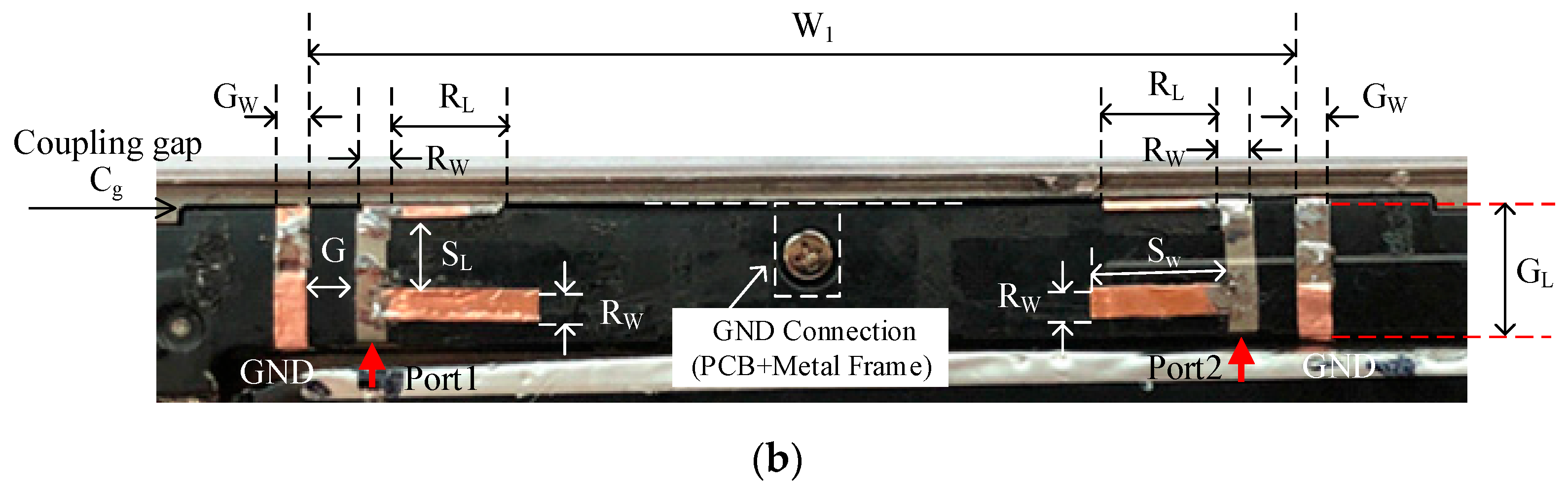
To address the limitations identified in Step 1, Step 2 employed a pattern-tuned antenna featuring geometrically optimized slots and coupling gaps [
Figure 8b]. The discrete sections were defined using critical design parameters, including the pattern length S
w, the radiating length R
L, and the coupling gap C
g. A central grounding connection between the PCB and the metal frame was added to ensure a stable current return path and to suppress uncontrolled parasitic resonances. The antenna geometry was further refined to enhance inter-port isolation and minimize the ECC values across the entire operating frequency. The final design parameters were as follows: top frame width W
1 = 45 mm, coupling gap C
g = 0.6 mm, and ground and antenna widths (G
W, R
W) 1.5 mm. The inter-element ground spacing G was 2 mm, and the radiating length (R
L) along the frame was reduced to 5 mm to improve the field distribution. For each antenna port, the stub length and width (S
L, S
W) were optimized to 3.5 and 6.5 mm, respectively, with a grounding length (G
L) beneath the slot of 7 mm. These geometric modifications were aimed at fine-tuning the resonant characteristics and enhancing impedance matching over the targeted frequency bands. Additionally, a common grounding strategy was employed to improve further port isolation. Specifically, a central grounding screw was used to establish a robust shared ground reference between the PCB and the metal frame, thereby stabilizing the electromagnetic environment and reducing undesired coupling between adjacent antenna elements.
The refined antenna layout enhanced inter-port isolation and substantially reduced the ECC across the n78 band, as validated by both the measured and simulated results of
Figure 9 and
Figure 10. The two-step design approach enabled the systematic identification of structural dependencies. The method balanced the impedance bandwidth, spatial isolation, and MIMO correlations within the constraints of realistic smartphone integration. Such iteration highlights the need to co-optimize electromagnetic performance and mechanical implementation when seeking to meet the stringent requirements of sub-6 GHz 5G MIMO systems.
Figure 9 shows the measured performance of the optimized two-port antenna after Step 2 [
Figure 8a]. This addressed the limitations of the initial four-port shared coupling design, with a particular focus on improving the ECC and inter-port isolation. As shown in
Figure 9a, both antenna ports (ANTs #1 and #2) achieve acceptable impedance matching, maintaining VSWR values below 3 across most of the n78 band (3.3–3.8 GHz). ANT #1 exhibits a broadband response with a primary resonance near 3.65 GHz and a secondary lobe around 4.6 GHz. ANT #2 maintains stable wideband matching across the 3.2–4.5 GHz range, ensuring robust sub-6 GHz performance. However, the measured isolation (∣S
21∣) between the ports remains relatively low, being a minimum of −4.21 dB at 3.78 GHz, indicating strong mutual coupling.
Figure 9b illustrates the corresponding radiation efficiency and ECC performance. Both antenna elements exhibit efficiencies greater than –6 dB across the bands, with peak values approaching −2 to −3 dB around 3.5 GHz. Despite the suboptimal isolation, the ECC values remain below 0.25 throughout the operational bands, with most of the n78 band exhibiting ECC values less than 0.2. This indicates that, although significant electromagnetic coupling remains, the far-field radiation patterns are sufficiently decorrelated to support the required MIMO diversity performance. These results confirm that the Step 2 configuration markedly improves the ECC compared to that of the original four-port design. However, further enhancements in isolation are necessary to fully meet the system-level MIMO requirements. Future work may incorporate decoupling techniques such as neutralization lines, grounded stubs, or parasitic isolation elements to suppress inter-port coupling further without compromising compact integration.
Figure 10 presents the measured performance of the final Step 2 configuration, corresponding to the re-tuned two-port antenna design of
Figure 8b. The structure was optimized to enhance port-to-port isolation while preserving broadband impedance matching and MIMO performance. As shown in
Figure 10a, both ANTs #1 and #2 exhibit wideband impedance matching with a VSWR ≤ 3 across the entire n78 band (3.3–3.8 GHz). The matching bandwidth is notably broader and more stable than that of the initial Step 2 configuration shown in
Figure 9, with the resonant frequencies now well centered within the desired operational range. Importantly, the port-to-port isolation is significantly improved, attaining a measured minimum of −12.39 dB at 3.53 GHz, an enhancement of almost 8 dB relative to that of the earlier design. Such improvement is attributable to the refined slot geometries and current path optimization along the metal frame. These factors effectively reduce electromagnetic coupling.
Figure 10b shows the corresponding radiation efficiencies and ECCs. Both antenna ports exhibit radiation efficiencies exceeding −6 dB across the bands, with the peaks approaching −2 dB near the resonance region. Crucially, the ECC values are drastically reduced, being as low as 0.001–0.002 within the 3.5–3.7 GHz range and remaining below 0.12 across the full n78 band. These results are well within the acceptable ECC threshold of 0.5 for effective MIMO operation and indicate highly decorrelated far-field radiation patterns. Collectively, these findings confirm that the final Step 2 antenna configuration achieves an optimal balance between impedance matching, radiation efficiency, port isolation, and the ECC. Compared to the Step 1 and preliminary Step 2 iterations, the final design satisfies both the radiation and system-level MIMO performance criteria, validating the feasibility of antenna integration into metal frame-based sub-6 GHz smartphone platforms.
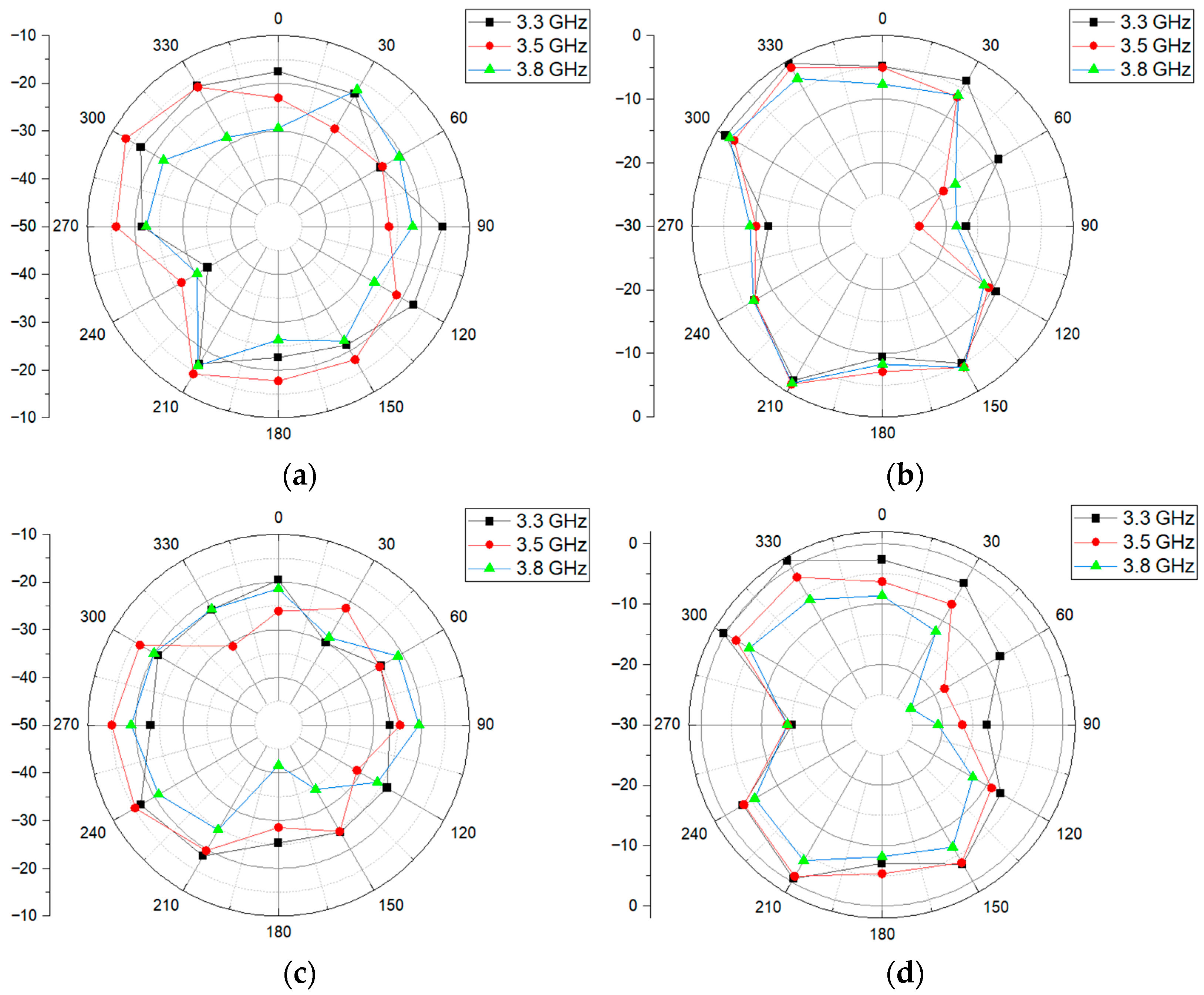
Figure 11 presents the measured far-field radiation patterns of ANTs #1 and #2 in both the E-plane (θ = 90°) and H-plane (φ = 90°) at three representative frequencies, 3.3, 3.5, and 3.8 GHz, in the n78 band. These measurements confirm that the antenna maintains consistent radiation behavior across the designated operational bandwidth.
Figure 11a,b show the radiation performance of ANT #1, which exhibits a moderately omnidirectional pattern in both planes. In the E-plane, a slightly stronger gain is observed toward the 0° and 180° directions but the overall gain variation across the three frequencies remains within 5 dB, indicating excellent pattern stability. In the H-plane, the radiation pattern is somewhat compressed along the 90–270° axis but retains a field distribution that adequately supports spatial diversity.
Figure 11c,d depict the corresponding results for ANT#2, which also exhibits stable radiation behavior across the entire frequency bands. At 3.5 GHz, a modest increase in directivity is observed in the E-plane; the forward gain is approximately −12 dB. Despite this, the pattern symmetry is well-preserved across all measured frequencies, with no significant nulls within ±30° of the boresight; this enhances link robustness in the real world. The results confirm that both antenna elements maintain a consistent angular coverage and pattern reproducibility throughout the n78 band. Such stability is crucial in terms of minimizing the envelope correlation and ensuring reliable MIMO performance, particularly in dynamic user hand interaction scenarios wherein the angular orientation of the antenna may vary significantly. All measurements were performed in a shielded anechoic chamber maintained at a temperature of 23 ± 2 °C and a relative humidity of 40–60% to ensure stable environmental conditions during testing. The measurement uncertainty was estimated by combining contributions from calibration accuracy, cable repeatability, and connector variability. Based on this assessment, the overall uncertainty in the measured S-parameter magnitude is approximately ±0.5 dB across the frequency range of interest.
Table 3 compares the performance of the new antenna to those of published sub-6 GHz MIMO designs in terms of bandwidth, radiation efficiency, the ECC, and physical size. Notably, the proposed design achieves superior isolation (>12 dB) and a lower ECC (<0.12), while maintaining a competitive size and good wideband matching.
6. Discussion and Future Work
The new metal frame coupled antenna system exhibits several advantages compared to previously reported sub-6 GHz MIMO designs. First, the measured isolation performance exceeds −12 dB, significantly better than earlier systems with isolation levels from near −4 to −10 dB. The enhancement is attributable to the refined coupling geometry and the centralized grounding between the PCB and the metal frame. In terms of the ECC, the new antenna achieves values below 0.12 across the entire n78 band, with a minimum of 0.001–0.002 in the 3.5–3.7 GHz range. These figures are better than those of conventional uniplanar or loop-type antennas; the ECCs often range from 0.15 to 0.2. Compared to recent studies such as [
1,
2,
7], the new antenna affords a better trade-off between performance and integration. Although [
10] reports isolation above 15 dB, our ECC performance (minimum 0.001) is superior and the structure is inherently more adaptable to diverse smartphone architectures. Furthermore, unlike Reference [
10], which presents results measured on a bare test board, our study evaluates the antenna performance when integrated into an actual smartphone platform. Therefore, the results in [
10] are likely to exhibit degraded performance under realistic operating conditions, whereas our measurements already reflect the constraints and effects associated with practical implementation.
Overall, the shared coupling architecture, combined with systematic isolation enhancement and ECC optimization, offers a practical and scalable antenna for sub-6 GHz 5G MIMO integration. The structure is especially well suited for high volume smartphone applications wherein the PCB space and frame access are limited. However, it should be noted that user interactions, especially hand proximity, may affect the current distribution on the metal frame and lead to performance variations. Accordingly, future work will include comprehensive evaluations using standardized hand phantoms and simulation models to quantify the potential impacts on impedance characteristics, efficiency, and MIMO correlation. Ensuring robust operation under realistic usage conditions is essential for practical deployment.
6.1. Frequency Shift Between Simulation and Measurement
The measured results showed a frequency shift exceeding 200 MHz compared to simulations (
Figure 4 vs.
Figure 7). This discrepancy is primarily attributed to four factors. First, the SMA connector and feed transition were modeled using a discrete port in CST Studio Suite 2024, without accounting for cable losses or parasitic effects, which can significantly impact resonance in compact designs. Second, the FR4 substrate properties (permittivity 4.3, loss tangent 0.025) can vary by ±10% due to material tolerances. Additionally, as shown in
Figure 6b, the placement of components, the battery, and the full-screen display contribute to further detuning when integrated into real devices. Third, fabrication tolerances of ±0.1 mm in slot and gap dimensions can induce resonance shifts between 50 MHz and 200 MHz. Finally, a mesh convergence study confirmed simulation stability, using a time domain solver over 0.1–6 GHz with –40 dB accuracy and approximately 3.3 million mesh cells. To further clarify the impact of individual parameter variations,
Table 4 provides a sensitivity analysis summarizing the estimated resonance frequency shifts associated with each factor:
6.2. Trade-Off Analysis Between Four-Port and Two-Port Designs
To validate the transition from the initial four-port configuration to the final two-port design, both antenna systems were fabricated and evaluated under identical free-space conditions. The four-port configuration exhibited a higher estimated MIMO channel capacity (approximately 15–18% increase) due to the additional spatial diversity and increased number of ports. The capacity was estimated using the well-known Shannon’s theorem applied to the measured S-parameters and simulated radiation efficiencies to account for correlation and per-port losses. MIMO channel capacity inherently depends on the number of antenna ports and the channel conditions, and it was calculated using the standard formula derived from Shannon’s capacity theorem. However, the measured isolation was limited to −4.6 dB, and the ECC exceeded 0.3 across significant portions of the n78 band, failing to meet the system-level performance requirements. Moreover, the four-port design required more complex impedance matching networks and precise dimensional control of the coupling gaps, which increased tuning complexity and reduced manufacturing yield. Mechanical integration studies further indicated that the battery, side buttons, and structural ribs restricted the available space along the metal frame, preventing consistent implementation of the four-port layout in production devices. In contrast, the two-port configuration provided more stable impedance matching, consistent isolation and reliable integration within the existing chassis envelope. For these reasons, the two-port design was selected as a more practical solution offering a balanced trade-off among capacity, complexity, and manufacturability.


