

Advanced Technology in ATSC3.0: Boosting Data Signal Rates Using Polarization Properties and FSS †


Abstract
1. Introduction
2. System Model
2.1. Channel Model
2.2. XPD
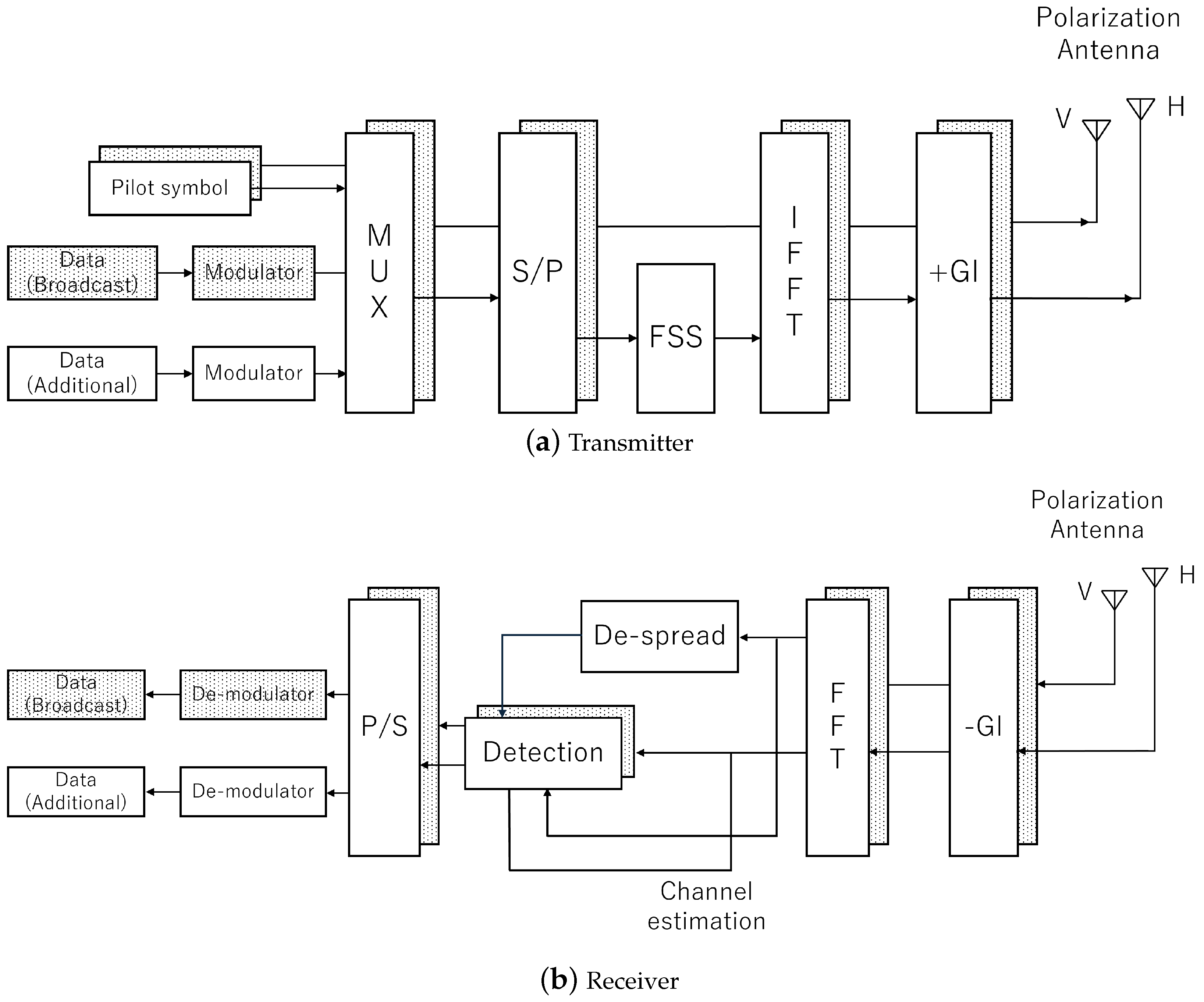
3. Proposed System
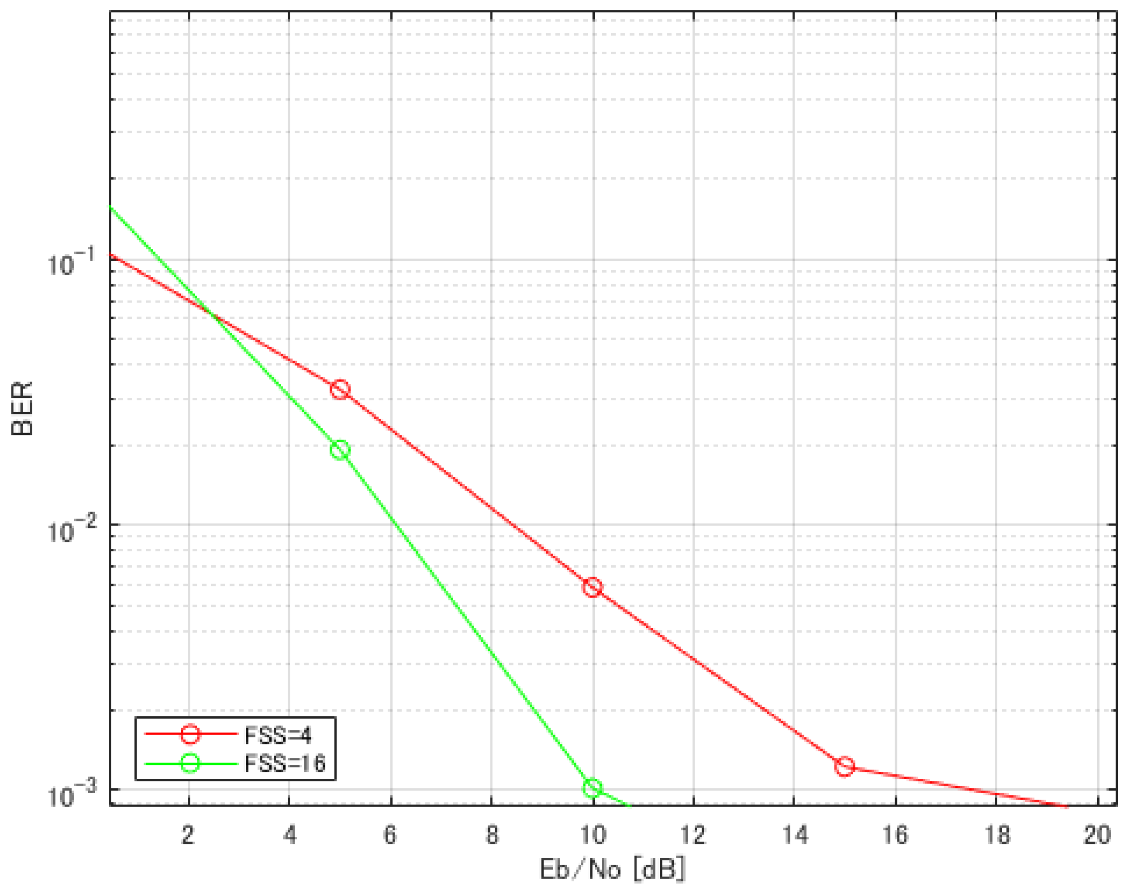
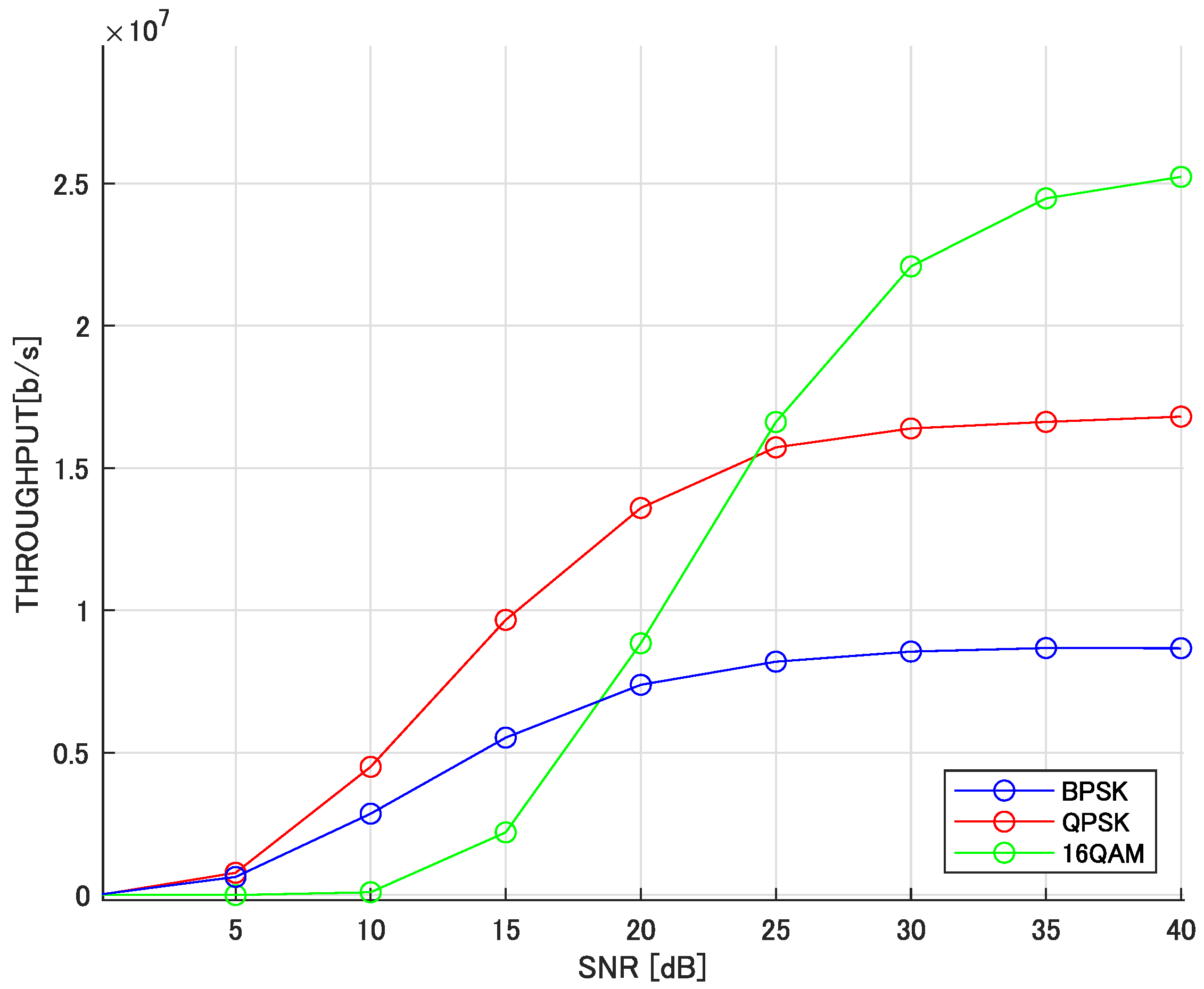
4. Computer Simulation Result
5. Conclusions
Author Contributions
Funding
Institutional Review Board Statement
Informed Consent Statement
Data Availability Statement
Conflicts of Interest
References
- Kang, D.; Park, H.; Park, S.I.; Kim, H.M.; Oh, W. Additional data transmission scheme using TxID signal for ATSC system. In Proceedings of the 2010 IEEE International Symposium on Broadband Multimedia Systems and Broadcasting (BMSB), Shanghai, China, 24–26 March 2010; pp. 1–3. [Google Scholar]
- Park, S.I.; Kim, H.M.; Kim, J. An improved data transmission scheme using TxID and Walsh sequences in the ATSC terrestrial DTV systems. In Proceedings of the 2011 IEEE 15th International Symposium on Consumer Electronics (ISCE), Singapore, 14–17 June 2011; pp. 79–82. [Google Scholar]
- ATSC Standard: A/322:2024-09; Physical Layer Protocol. Advanced Television System Committee: Washington, DC, USA, 2024.
- ATSC Digital Television Standard A/53; ATSC Digital Television Standard, Parts 1–6. Advanced Television System Committee: Washington, DC, USA, 2007.
- ATSC Digital Television Standard A/331; Signaling, Delivery, Synchronization, and Error Protection. Advanced Television System Committee: Washington, DC, USA, 2025.
- Wang, X.; Wu, Y.; Caron, B. Transmitter identification using embedded pseudo random sequences. IEEE Trans. Broadcast. 2004, 50, 244–252. [Google Scholar] [CrossRef]
- Burr, A.G. Capacity improvement of CDMA systems using M-ary code shift keying. In Proceedings of the 1991 Sixth International Conference on Mobile Radio and Personal Communications, Coventry, UK, 9–11 December 1991; pp. 63–67. [Google Scholar]
- Cha, J.; Yoon, B.; Hur, N.; Lee, Y.; Kim, S. New TxID sequence and Matched Filter implementation for ATSC DTV. In Proceedings of the 2005 International Conference on Solid State Devices and Materials, Kobe, Japan, 12–15 September 2005; Extended Abstracts. Volume 2005, pp. 668–669. [Google Scholar]
- Lim, B.-M.; Kwon, S.; Ahn, S.; Park, S.-I.; Lee, J.-Y.; Hur, N.; Kim, H.M.; Kim, J. Laboratory Test Analysis of TxID Impact into ATSC 3.0 Preamble. In Proceedings of the 2018 IEEE International Symposium on Broadband Multimedia Systems and Broadcasting (BMSB), Valencia, Spain, 6–8 June 2018; pp. 1–3. [Google Scholar]
- Park, S.I.; Kim, J.; Kim, H.M. Effect of TxID signal on the performance of the legacy ATSC terrestrial DTV receivers. In Proceedings of the 2011 IEEE International Conference on Consumer Electronics (ICCE), Las Vegas, NV, USA, 9–12 January 2011; pp. 453–454. [Google Scholar]
- Li, T.; Qian, B.; Chen, X. XPD Enhancement and Decoupling of ±45° Dual-polarized Antenna Array by Parasitic Strips. In Proceedings of the 2023 IEEE 6th International Conference on Electronic Information and Communication Technology (ICEICT), Qingdao, China, 21–24 July 2023; pp. 162–165. [Google Scholar]
- Ahn, C.; Kamio, K.; Takahashi, S.; Harada, H. Reverse link performance improvement for an wideband OFDM using Alamouti coded heterogeneous polarization antennas. In Proceedings of the ISCC 2004 Ninth International Symposium on Computers And Communications (IEEE Cat. No.04TH8769), Alexandria, Egypt, 1–28 July 2004; Volume 2, pp. 702–707. [Google Scholar]
- Asci, Y.; Secmen, M.; Altuntas, M. Wideband Omnidirectional Coplanar Waveguide-Fed Coaxial Dipole Antenna for VHF/UHF Communication Bands with Improved XPD. In Proceedings of the 2023 31st Telecommunications Forum (TELFOR), Belgrade, Serbia, 21–22 November 2023; pp. 1–4. [Google Scholar]
- Jung, H.; Park, S.-I.; Lim, B.-M.; Kwon, H.; Hur, N.; Jeon, S.; Kim, H.; Kim, J. Impact of Cross-Polarization Discrimination for ATSC 3.0 MIMO System. In Proceedings of the 2021 IEEE International Symposium on Broadband Multimedia Systems and Broadcasting (BMSB), Chengdu, China, 4–6 August 2021; pp. 1–3. [Google Scholar]
- Ahn, C.J.; Har, D.; Omori, T.; Hashimoto, K. Reinforced Multiuser Diversity Using Frequency Symbol Spreading and Adaptive Subcarrier Block Selection for OFDMA; The Institute of Electronics, Information and Communication Engineers (IEICE): Tokyo, Japan, 2009; IEICE Technical Report, No. 266, CS2009-44; Volume 109, pp. 13–18. [Google Scholar]
- Kojima, S.; Watanabe, K.; Murata, K.; Ahn, C.-J. Joint Adaptive Modulation and Transmit Power Control on FSS-OFDM Mobile Relay System. J. Signal Process. 2019, 23, 83–93. [Google Scholar] [CrossRef]
- Ahn, C.J.; Harada, H.; Kamio, Y. Superimposed Frequency Symbol Based Adaptive Downlink OFDM with Frequency Spreading and Equalization. IEICE Trans. Commun. 2006, E89-B, 500–508. [Google Scholar] [CrossRef]
- Kuroha, A.; Ahn, C.J.; Omori, T.; Hashimoto, K. Multiuser Diversity OFDMA using Power Priority Selection and Adaptive Clipping. Int. J. Distrib. Syst. Technol. (IJDST) 2014, 5, 18–30. [Google Scholar] [CrossRef]
- Ida, Y.; Ahn, C.; Kamio, T.; Fujisaka, H.; Haeiwa, K. Complexity Reducing of Subcarrier Selection Method Based on Low Granularity Block for TFI-MUDiv/OFDMA. Recent Patents Signal Process. 2012, 2, 68–75. [Google Scholar]
- Ukaji, F.; Ahn, C.; Omori, T.; Hashimoto, K. Performance enhancement with applying FSS and ASB method for MU-MIMO. In Proceedings of the 2016 IEEE International Conference on Industrial Technology (ICIT), Taipei, Taiwan, 14–17 March 2016; pp. 860–865. [Google Scholar]
- Tanaka, R.; Handa, Y.; Hayakawa, H.; Cha, J.; Ahn, C.-J. Performance Enhancement of ATSC3.0 Using Polarization Property and Frequency Symbol Spreading. In Proceedings of the 2024 IEEE 29th Asia Pacific Conference on Communications (APCC), Bali, Indonesia, 5–7 November 2024; pp. 229–234. [Google Scholar]


| Broadcasting | Data Communication | |
|---|---|---|
| Modulation Scheme | QPSK | QPSK |
| Number of Subcarriers | 64 | 16 |
| Guard Interval | 16 | - |
| Spreading Code | - | Hadamard code |
| Spreading Length | - | 4, 16 |
| Data Length | 20 | 20 |
| Pilot Signals | 2 | 2 |
| Channel Model | 5 path Rayleigh fading | 5 path Rayleigh fading |
| Transmission Rate | 20 Mbps | 20 Mbps |
| Doppler frequency | 10 Hz | 10 Hz |
| Modulation | QPSK | 16QAM |
|---|---|---|
| SNR [dB] |
Disclaimer/Publisher’s Note: The statements, opinions and data contained in all publications are solely those of the individual author(s) and contributor(s) and not of MDPI and/or the editor(s). MDPI and/or the editor(s) disclaim responsibility for any injury to people or property resulting from any ideas, methods, instructions or products referred to in the content. |
© 2025 by the authors. Licensee MDPI, Basel, Switzerland. This article is an open access article distributed under the terms and conditions of the Creative Commons Attribution (CC BY) license (https://creativecommons.org/licenses/by/4.0/).
Share and Cite
Tanaka, R.; Hayakawa, H.; Handa, Y.; Cha, J.; Ahn, C.-J. Advanced Technology in ATSC3.0: Boosting Data Signal Rates Using Polarization Properties and FSS. Appl. Sci. 2025, 15, 6306. https://doi.org/10.3390/app15116306
Tanaka R, Hayakawa H, Handa Y, Cha J, Ahn C-J. Advanced Technology in ATSC3.0: Boosting Data Signal Rates Using Polarization Properties and FSS. Applied Sciences. 2025; 15(11):6306. https://doi.org/10.3390/app15116306
Chicago/Turabian StyleTanaka, Riku, Hiroya Hayakawa, Yudai Handa, Jaesang Cha, and Chang-Jun Ahn. 2025. "Advanced Technology in ATSC3.0: Boosting Data Signal Rates Using Polarization Properties and FSS" Applied Sciences 15, no. 11: 6306. https://doi.org/10.3390/app15116306
APA StyleTanaka, R., Hayakawa, H., Handa, Y., Cha, J., & Ahn, C.-J. (2025). Advanced Technology in ATSC3.0: Boosting Data Signal Rates Using Polarization Properties and FSS. Applied Sciences, 15(11), 6306. https://doi.org/10.3390/app15116306