Article

Mechanical Performance Enhancement of Self-Decoupling Magnetorheological Damper Enabled by Double-Graded High-Performance Magnetorheological Fluid

1
School of Civil Engineering and Architecture, Anhui Polytechnic University, Wuhu 241000, China
2
Anhui Engineering Research Center of Green Building and Digital Construction, Wuhu 241000, China
3
Department of Engineering Mechanics, Hohai University, Nanjing 210098, China
4
School of Civil and Transportation Engineering, Ningbo University of Technology, Ningbo 315211, China
*
Authors to whom correspondence should be addressed.
Appl. Sci. 2025, 15(11), 6305; https://doi.org/10.3390/app15116305
Submission received: 25 April 2025 / Revised: 30 May 2025 / Accepted: 2 June 2025 / Published: 4 June 2025

Abstract

:
Conventional magnetorheological fluids (MRFs) exhibit a constrained shear strength that restricts their deployment in high-performance damping systems. This study introduces a dual-axis innovation strategy combining material science and device physics to fundamentally redefine MRF capabilities. We develop a hierarchical particle architecture through the controlled integration of micro/nano-sized carbonyl iron particles (CIPs), enhanced by polyethylene glycol/oleic acid surface engineering to optimize magnetic chain formation and interfacial bonding. The engineered MRF demonstrates a shear yield strength of 99.6 kPa at 0.757 T, surpassing conventional single-component MRFs by a significant margin. Integrated with a self-decoupling damper that isolates magnetic flux from mechanical motion, this synergistic design achieves exceptional force modulation: damping forces scale from 281.5 kN (5 mm stroke) to 300 kN (60 mm stroke), with current-regulated adjustability factors reaching 3.34. The system exhibits substantial improvements in both maximum damping force (93.9 kN enhancement) and energy dissipation efficiency compared to standard MRF dampers. Through co-optimization of the particle architecture and magnetic circuit design, this work establishes new performance benchmarks for smart fluid technology. The achieved force capacity and dynamic response characteristics directly address critical challenges in seismic engineering and industrial vibration control, where extreme load-bearing requirements demand simultaneous high strength and tunable damping capabilities.

1. Introduction

Magnetorheological fluids (MRFs) have become increasingly significant in smart materials research due to their unique ability to reversibly transition from a liquid to a semi-solid state under the influence of a magnetic field. This transformation largely affects the shear mechanical performance of MRFs, which is dependent on several factors including the type and distribution of magnetic particles, the carrier fluid, and the role of additives and surfactants. Recent studies have indicated that particle size distribution plays a crucial role in improving the magnetic and mechanical behavior of MRFs [1,2,3]. Specifically, a double-graded distribution involving various particle sizes can enhance the field-responsive behavior and mechanical properties of MRFs by optimizing particle packing density and magnetic field interactions [4,5]. Moreover, the choice of carrier fluid, whether involving silicone oil, polyalphaolefin, or other substances, substantially influences viscosity and thermal stability, thus affecting the shear response of MRFs under applied magnetic fields [6,7,8]. Additives such as oleic acid and surfactants such as Span 80 are often incorporated to further improve the dispersion stability and modulate rheological properties without inducing significant sedimentation issues [9,10,11].
In parallel, magnetorheological (MR) dampers, which utilize these advanced MRFs, have exhibited significant advancements in dynamic mechanical performance, particularly in terms of damping force output. MR dampers capitalize on the tunable viscosity of MRFs to provide varying damping forces that can be precisely controlled by external magnetic fields [12,13,14]. This adaptability makes them ideal for applications in vibration control across different sectors, including the architectural [15], automotive, and aerospace fields [16,17]. The enhancements in MR damper performance are typically assessed by evaluating the damping force range, response time, and energy dissipation efficiency [18,19,20]. The implementation of double-graded MRFs within these dampers has been found to significantly enhance these parameters, as these specially formulated fluids optimize the magnetic flux distribution and reduce the occurrence of phenomena such as particle clustering and chain breakage under stress [21,22,23].
The development of a self-decoupling mechanism in MR dampers further augments their mechanical performance by minimizing the interference and interaction between the magnetic circuit and mechanical components. Through decoupling, the magnetic field effects are streamlined, allowing for more efficient force transmission and reduced energy losses [24,25,26,27]. This innovation is pivotal in expanding the functional range of MR dampers, enabling them to be more resilient and responsive under variable load conditions. The combination of double-graded high-performance MRFs and self-decoupling mechanisms results in high-capacity MR dampers that are not only efficient at damping vibrations but also adaptive to the evolving demands of modern engineering systems [28,29,30,31]. Hence, continuous research into optimizing the formulation of MRFs and the structural design of MR dampers is critical in advancing the application potential of these smart damping systems [32,33,34].
This study demonstrates a high-performance magnetorheological fluid (HP-MRF) synthesized by dispersing single- and double-graded carbonyl iron particles (CIPs) in a composite carrier system combining a sol solution with methyl silicone oil. Furthermore, the optimized HP-MRF was subsequently implemented in a previously designed self-decoupling MR damper to investigate its dynamic hysteretic behavior. These studies establish that CIP grading optimization in MRFs enables exceptional damper performance for advanced vibration control applications.

2. Materials and Methods

2.1. Materials

The primary materials utilized in the preparation of the high-performance MRFs (HP-MRFs) included gelatin, agaropectin, methyl silicone oil, glycerol as a thixotropic agent, polyethylene glycol (PEG-400) and oleic acid as particle surfactants, and absolute ethyl alcohol as a dispersant, all of which were analytically pure and purchased from Sinopharm Group Chemical Reagent Co., Ltd., Shanghai, China. Furthermore, carbonyl iron particles (CIPs) with a mean particle diameter of 3.5 µm were acquired from Jiangsu Tianyi Ultrafine Metal Powder Co., Ltd., located in Xuyi, China.

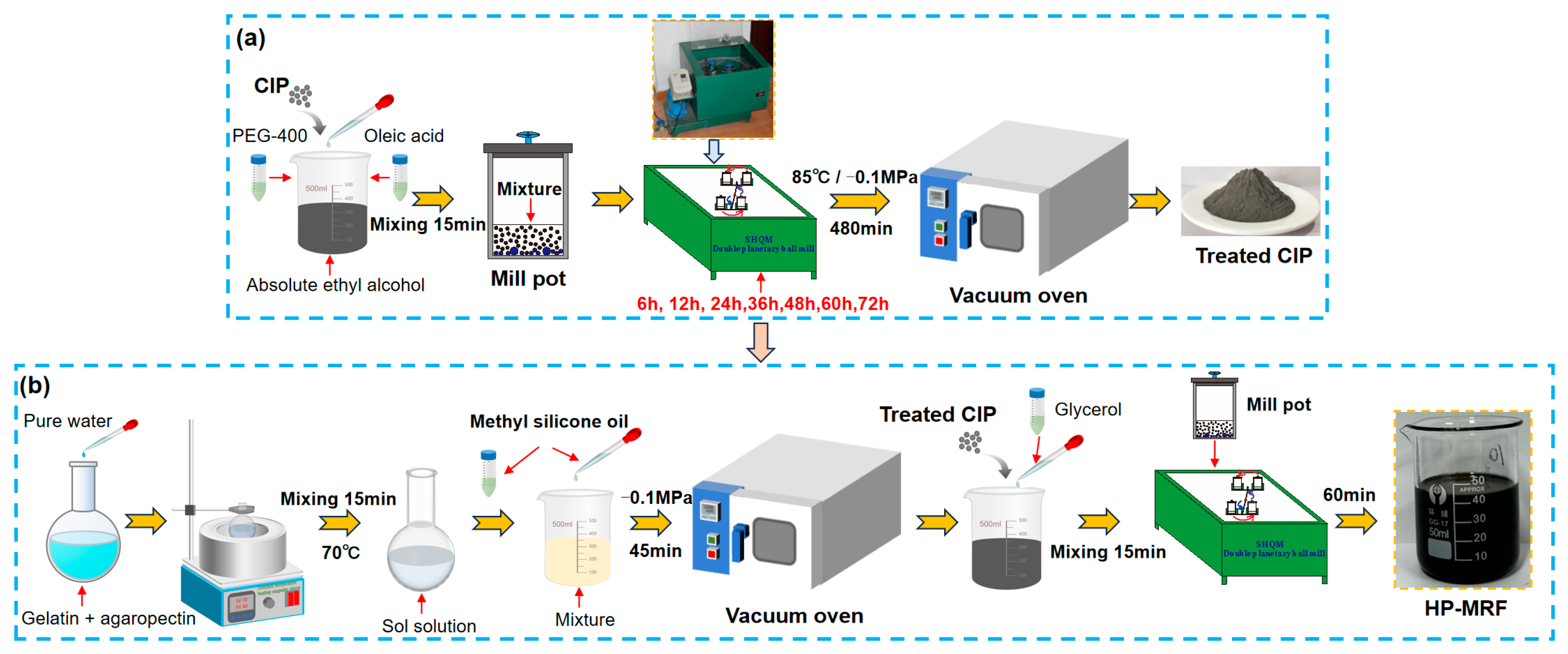
2.2. Preparation Process and Characterization

An HP-MRF is a colloidal suspension system in which soft magnetic particles are uniformly distributed within the carrier. This uniform dispersion is essential for achieving optimal performance in its applications. Consequently, the soft magnetic particles were evenly distributed within the carrier through the ball mill dispersion method to formulate HP-MRFs. Figure 1 illustrates the preparation process.
Recent research findings have demonstrated that particle surfactants such as PEG-400 and oleic acid can significantly enhance the shear yield strength and stability of MRFs [35]. The procedure for surface active agent treatment in CIPs is illustrated in Figure 1a:
(1)
CIPs (initial particle size: 3.5 µm), surfactants such as PEG-400 and oleic acid, and an absolute ethyl alcohol dispersion medium were measured in proportion and placed in a beaker, followed by mixing with an electric stirrer for 15 min.
(2)
The amalgamation was transferred into a milling pot. Steel balls of varying sizes, although with identical diameters and numerical ratios, were subsequently introduced into the mill pots.
(3)
The mill pots were firmly positioned in the SHQM double planetary ball mill, which operated at a constant rotational speed. Subsequently, ball milling was conducted for durations of 6, 12, 24, 36, 48, 60, and 72 h for the different CIP samples with various particle sizes.
(4)
The ball mill pots containing the mixture post ball milling were placed in a vacuum oven at 85 °C for drying at a vacuum pressure of −0.1 MPa for a duration of 480 min to eliminate the absolute ethyl alcohol, resulting in the acquisition of the treated CIPs after drying and cooling.
Secondly, the procedure of HP-MRF preparation is illustrated in Figure 1b:
(1)
The measured quantities of gelatin and agaropectin were combined with purified water at 70 °C in a flask for 15 min to create a sol solution.
(2)
Methyl silicone oil was weighed and added to the sol solution, which was thoroughly mixed before being transferred to a vacuum oven for decompression at −0.1 MPa for 45 min.
(3)
The modified CIPs and glycerol were weighed and incorporated into the mixture following vacuum decompression and then mixed for 15 min.
(4)
The mixture was placed in the mill pots to achieve uniform dispersion for 60 min in the double planetary ball mill, resulting in the acquisition of HP-MRF samples.
The phase analysis of untreated and surfactant-treated CIPs was conducted using a D8 Advance X-ray diffractometer (Bruker Co., Karlsruhe, Germany), and the particle size of the ball-milled CIPs was assessed. A testing apparatus utilizing a D8 Advance X-ray diffractometer was constructed to assess the particle size distribution of the CIPs post ball milling, as seen in Figure 2a. Figure 2b illustrates the particle size distribution of ball-milled CIPs across varying durations, indicating that as the ball milling period increases, the size of the ferromagnetic particles diminishes from an initial 3.5 µm to 300 nm after 72 h of milling. Particle sizes of 900 nm, 600 nm, and 360 nm, corresponding to 12 h, 24 h, and 60 h of ball milling, respectively, were chosen for the CIPs. Furthermore, as illustrated in Figure 2c, pronounced diffraction peaks (2θ = 40.4°, 45°, and 82.6°) are evident in both treated and untreated CIPs, aligning well with the standard spectrum of iron (Fe), albeit with variations in peak intensity. The diffraction peak intensity of the treated CIP is somewhat reduced, maybe due to the adsorption of a coating of active agent on the particle surface, but the crystal structure of Fe remains unchanged post treatment. The rheological properties of the synthesized HP-MRF samples were evaluated using the MCR302 rotational rheometer system (Anton Paar Co., Graz, Austria), which includes an MCR302 rheometer (host), a magnetic field excitation module, and a temperature control device, as illustrated in Figure 2d. In the rheological studies, the rotational speed of the PP20 parallel plate rotor was maintained at 100 s−1, while the magnetic flux density was incrementally adjusted from 0 to 0.757 T. In addition, all HP-MRF samples were tested at 25 °C through the temperature control device.
This work presents 12 groups of well-dispersed single- and double-graded HP-MRF samples, each containing 72% CIP, generated using the aforementioned procedure. The primary components are presented in Table 1. In the formulation of the carrier containing 25%, the mass fraction of methyl silicone oil was 60%, while that of the gelatin/agaropectin sol solution was 40%. The dose ratio of gelatin to agaropectin in the sol solution was 3:1.

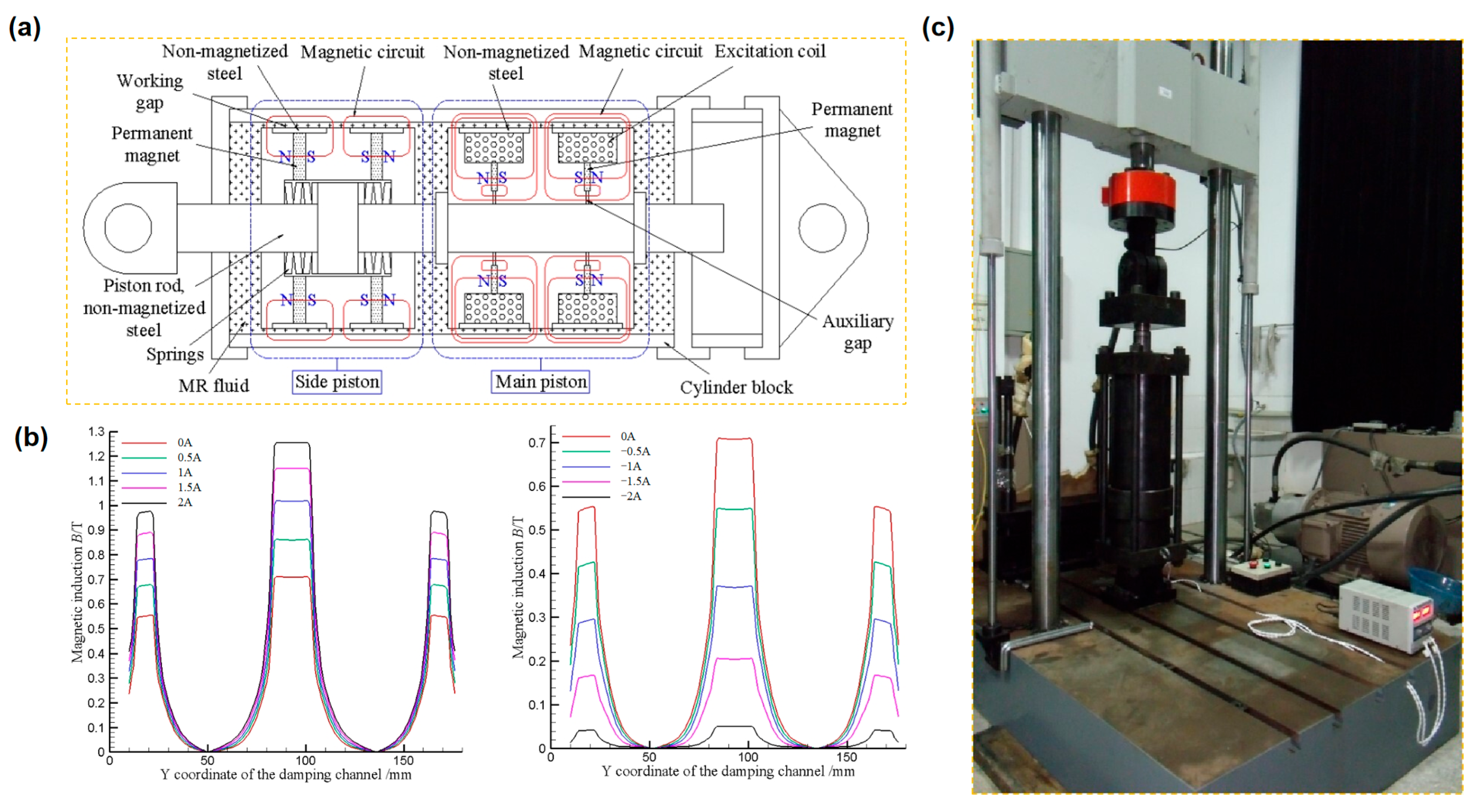
2.3. Properties of Self-Decoupling MR Dampers

The previously engineered and manufactured self-decoupling MR damper with a standard MRF includes two piston types [36]: a primary piston and an auxiliary piston. Figure 3a illustrates that these pistons were linked by a decoupling mechanism (disk spring), which significantly affected the damping performance. At large displacements, the damper’s maximum output was roughly double that at minimal displacements, thus providing a sufficient safety margin. The coil within the damper can produce magnetic fields that either align with or oppose the permanent magnets, allowing for fine modulation of the damping force magnitude as needed. Variations in the input current of the excitation coil, ranging from −2 A to 2 A, provide distinct magnetic induction intensities at the working gap, as depicted in Figure 3b. It is apparent that when the current is positive, the magnetic induction intensity at the operational gap escalates with the augmentation of current. Nevertheless, when the current increases, the enhancement in magnetic induction intensity near the operational gap decreases. This effect is ascribed to the nonlinearity of the material’s magnetic permeability and its similarity to the saturation magnetic induction strength. Conversely, when the current is negative, the magnetic induction intensity at the operational gap diminishes as the current magnitude increases. Consequently, it is evident that the permanent magnet and the excitation coil interact synergistically, facilitating bidirectional modulation of the damping force of the main piston while maintaining the damper’s output force during power failure. Moreover, in civil engineering structures exposed to seismic and wind-induced vibrations, the duration of MR damper operation is significantly shorter than the intervals of inactivity. A significant disadvantage of these dampers is the sedimentation of solid-phase particles in the MRF during extended static positioning, which undermines the stability of the MRF. The inclusion of permanent magnets in the self-decoupling MR damper alleviates this problem by diminishing particle sedimentation, therefore improving their operational stability.
The dynamic characteristics of the self-decoupling MR damper filled with the prepared HP-MRFs were obtained using the servo dynamic testing machine (SDS-300), as seen in Figure 3c. The experiment utilized a sine wave input excitation curve and employed a displacement control approach. The test parameters were as follows: a large displacement of 60 mm at a frequency of 0.1 Hz and a small displacement of 5 mm at frequencies of 0.1 Hz, 1.0 Hz, and 2.5 Hz. For each test condition, current excitations of −2.0 A, −1.0 A, 0 A, 1.0 A, and 2.0 A were employed.

3. Results and Discussion

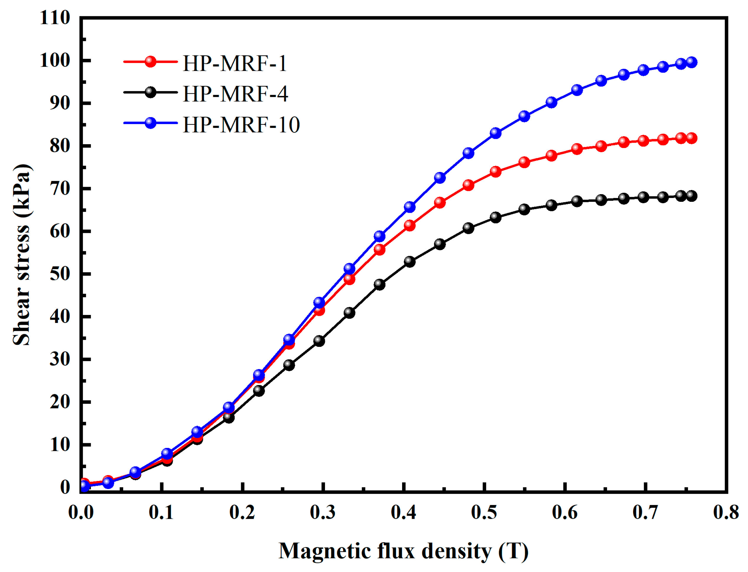
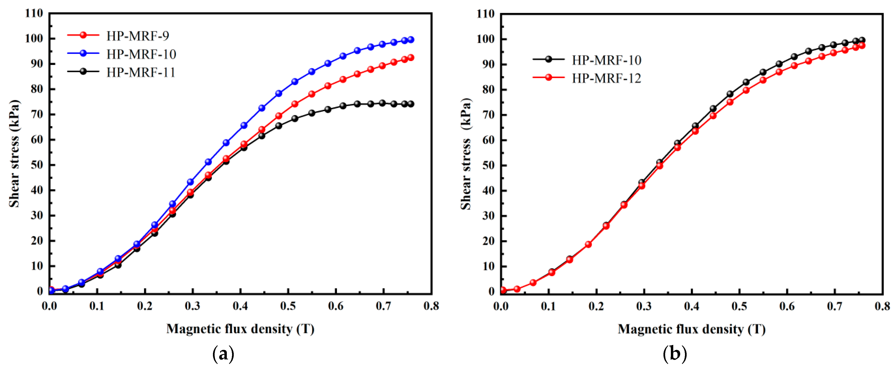
3.1. Rheological Properties of the HP-MRFs

The correlation between shear stress and magnetic flux density in single-graded HP-MRFs is illustrated in Figure 4. This figure illustrates that at a magnetic flux density of 0.757 T, the shear yield strength of HP-MRF-1 is measured at 81.8 kPa, in contrast to the shear yield strength of HP-MRF-8, which is recorded at 45 kPa. As we progress from HP-MRF-1 to HP-MRF-8, there is a noticeable decrease in shear stress, suggesting that the volume of soft magnetic particles diminishes progressively with the reduction in particle size. Magnetic dipole and coupled field model theory [37,38] suggests that the magnetic force between particles diminishes progressively, leading to a gradual reduction in shear stress. Simultaneously, as the magnetic induction intensity gradually increases, all HP-MRF samples approach magnetic saturation at 0.5 T. This suggests that when the mass fraction of soft magnetic particles remains constant, the size of the particles has minimal impact on the magnetic saturation of HP-MRFs.
To evaluate the performance of double-graded HP-MRFs against single-graded HP-MRFs, the experimental results of HP-MRF-1, 4, and 10 were chosen for comparative analysis, as illustrated in Figure 5. Table 1 illustrates that the soft magnetic particles in HP-MRF-1 consist of unmilled CIPs, HP-MRF-4 contains CIPs that have undergone 24 h of ball milling, and HP-MRF-10 comprises a mixture of unmilled and 24 h ball-milled CIPs, with unmilled CIPs constituting 90% and 24 h ball-milled CIPs making up 10% of the soft magnetic particles. The shear yield strength of HP-MRF-10 is 99.6 kPa, exceeding that of HP-MRF-1 and HP-MRF-4 by 17.8 kPa and 31.3 kPa, respectively.
Figure 6a illustrates the variation in particle sizes of the sub-micron particles across the HP-MRF-9, 10, and 11 samples, which were subjected to ball milling for durations of 12 h, 24 h, and 60 h, respectively. All other conditions remain the same. The shear yield strengths observed for the HP-MRF-9, HP-MRF-10, and HP-MRF-11 samples were recorded at 92.5 kPa, 99.6 kPa, and 74.1 kPa, respectively. The figure illustrates that HP-MRF-10, which underwent 24 h of ball milling with soft magnetic particles, exhibits the most favorable MR effect. In contrast, HP-MRF-11, subjected to 60 h of ball milling, demonstrates the least effective MR response, with its shear stress falling below that of the single-graded HP-MRF-1 that did not undergo ball milling. The particle size in HP-MRF-11 measures just 360 nm, indicating a further reduction in the average size of the particles. The shear stress displays a reduction. Consequently, the particle size of the sub-micron particles in the double-graded HP-MRFs should be optimized to significantly enhance their shear stress. Figure 6b illustrates that the sub-micron soft magnetic particles in the HP-MRF-10 and 12 samples exhibit identical particle sizes, as both had undergone ball milling for 24 h; however, their respective contents differ, being 10% and 8%, respectively. The shear yield strength of HP-MRF-12, containing a reduced amount of sub-micron soft magnetic particles, is measured at 97.5 kPa. Nonetheless, the content must not be excessively high, as an increase in content will lead to a further reduction in the average particle size, subsequently decreasing the shear stress. Consequently, in the double-graded HP-MRFs, the concentration of sub-micron particles must also be kept at a moderate level. At present, the shear yield strength of the major commercial MRFs is concentrated within the range of 50–70 kPa; among these, LORD products have a shear yield strength of approximately 50–60 kPa [39]. In comparison with the MRFs available on the market, the shear performance of the prepared HP-MRFs is enhanced, but their temperature and sedimentation stability will be further investigated and verified in the next stage.

3.2. Dynamical Mechanical Properties of the Self-Decoupling MR Damper

In this study, based on the maximum shear yield strength, HP-MRF-10 was chosen as the filler for the self-decoupling MR damper. The dynamic characteristic curve of the self-decoupling MR damper is illustrated in Figure 7, with the input current range spanning from −2.0 A to 2.0 A. This figure illustrates that the damping force of the damper rises as the input current increases and diminishes as the current decreases across all working conditions.
When the displacement is limited to 5 mm, meaning that the amplitude of the self-decoupling MR damper remains within 5 mm of the maximum compression of the disk spring, only the main piston operates independently. The dynamic characteristic curve of the damper is illustrated in Figure 7a–c. At an applied frequency of 0.1 Hz, the output force of the damper can be adjusted within a range of 77.9 kN to 260.2 kN, using the damping force at the equilibrium position as a reference point. The adjustability factor for the damping force is roughly 3.34. At an applied frequency of 1.0 Hz, the output force of the damper can be adjusted within a range of 107.8 kN to 276.6 kN, with the damping force being adjustable by a factor of approximately 2.57. At an applied frequency of 2.5 Hz, the output force of the damper can be adjusted within a range of 112.8 kN to 281.5 kN, with the damping force being adjustable by a factor of approximately 2.50.
In scenarios where there is a large displacement of 60 mm, specifically when the amplitude of the self-decoupling MR damper surpasses the maximum compression of the disk spring by 5 mm, the main piston and the auxiliary piston operate in a coordinated manner. Figure 7d illustrates the dynamic characteristic curve of the damper. The output force can be adjusted within a range of 262.8 kN to 300 kN under large displacement conditions, while the damping force can be adjusted to approximately 1.14.
The force–displacement hysteresis curves directly indicate the energy storage and consumption of the self-decoupling MR damper. To quantitatively elucidate the damping performance of the self-decoupling MR damper, performance parameters including equivalent stiffness (Kh), post-yield stiffness (Kd), yield force (Qd), and equivalent damping ratio (heq) can be derived from the dynamic hysteretic curves. Figure 8 illustrates the schematic diagram of performance parameters, with Q denoting shear behavior and D indicating displacement.
The performance parameter calculation formulas [40] are given in Equation (1) to Equation (4):
K h = Q max Q min D max D min
K d = K d + K d 2 = 1 2 Q max Q d + D max + Q min Q d D min
Q d = 1 2 ( Q d + Q d )
h eq = 1 4 π Δ W W = 1 2 π Δ W K h D max 2
where Qmax is the maximum shear force; Qmin is the minimum shear force; Dmax is the maximum displacement; Dmin is the minimum displacement; Qd+ and Qd are the intersection points of the positive and negative hysteresis curves and shear axis, respectively; Kd+ and Kd are the positive and negative yield stiffness, respectively; heq is the equivalent damping ratio; ΔW is the envelope area of the hysteresis curve; and W is the elastic potential energy.
The results of the self-decoupling MR damper calculations are shown in Table 2. The equivalent damping ratio heq in large-displacement conditions surpasses that observed in small-displacement scenarios. At an applied displacement of 5 mm, the heq values vary between 37.62% and 45.39%. In contrast, at a displacement of 60 mm, the heq values range from 55.03% to 57.29%. Thus, it is clear that displacement stands out as the primary factor affecting heq, while frequency, current, and magnetic field have comparatively minor effects on heq.
Figure 9a illustrates the changes in equivalent stiffness Kh and yield force Qd as a function of frequency, considering various input currents and a small displacement of 5 mm. The utilization of specific frequency and current input can improve both the equivalent stiffness Kh and the yield force Qd. At an input of −2.0 A, the Kh value ranges from 18.31 kN/mm at 0.1 Hz to 27.56 kN/mm at 2.5 Hz, indicating a change rate of 50.5%. Additionally, the value of Qd ranges from 82.00 kN at 0.1 Hz to 120.05 kN at 2.5 Hz, indicating a change rate of 46.4%. As the current transitions from −2.0 A to 2.0 A at an applied frequency of 0.1 Hz, the value of Kh increases from 18.31 kN/mm to 51.85 kN/mm, indicating a change rate of 183.2%. Additionally, the value of Qd ranges from 82.00 kN at −2.0 A to 247.55 kN at 2.0 A, indicating a change rate of 201.9%. The various factors indicate that the self-decoupling MR damper is capable of adapting to changes in applied frequency and displays a stiffness characteristic that is influenced by current input. Figure 9b demonstrates the relationship between equivalent stiffness Kh and yield force Qd as a function of input currents at a large displacement of 60 mm. The maximum damping force obtained is constrained by the measurement range of the testing machine, which does not exceed 300 kN. Consequently, as the input current rises from −2.0 A to 2.0 A, the values of Kh and Qd appear to stabilize.
An earlier investigation into the self-decoupling MR damper utilized a common MRF as the filler, which exhibited a maximum shear yield strength of 54 kPa. Figure 10 shows the comparison of the dynamic mechanical properties for the self-decoupling MR damper filled with this common MRF and the HP-MRF. Figure 10a illustrates that, in comparison to the previous study, the damping force of the self-decoupling MR damper filled with the HP-MRF is enhanced by a maximum of 93.9 kN at 1.0 Hz. Furthermore, enhancements are made to the factor of adjustability across various currents. Figure 10b–d illustrate that a comparison of the calculated parameters of equivalent stiffness Kh and equivalent damping ratio heq under small displacement reveals that the self-decoupling MR damper with the HP-MRF demonstrates superior energy consumption capacity across various input currents.
Table 3 compares the damping force of the proposed system with that of existing large-scale MR dampers. The self-decoupling mechanism enables a 300 kN damping force, outperforming prior MR dampers filled with a conventional MRF with single-graded CIPs.

4. Conclusions

This study involved the acquisition of CIPs with varying particle sizes through the ball milling method. Subsequently, a range of HP-MRF samples were prepared by dispersing both single-graded and double-graded CIPs into a compound consisting of a sol solution and methyl silicone oil. A rotational rheometer was employed to analyze the correlation between shear stress and magnetic flux density for the HP-MRF samples. Additionally, the previously developed self-decoupling MR damper was filled with HP-MRF, and the dynamic mechanical properties were evaluated under both small and large displacements. The findings are outlined as follows:
(1)
In the case of HP-MRFs featuring single-graded CIPs, it is observed that the shear stress across all samples rises in conjunction with an increase in magnetic flux density. Additionally, the shear yield strength exhibits a decline from 81.8 kPa to 45 kPa as the particle size is progressively reduced. In the case of HP-MRFs featuring double-graded CIPs, the shear yield strength of HP-MRF-10 can reach 99.6 kPa. This suggests that an optimal combination of particle sizes effectively contributes to enhancing the shear yield strength of the HP-MRF.
(2)
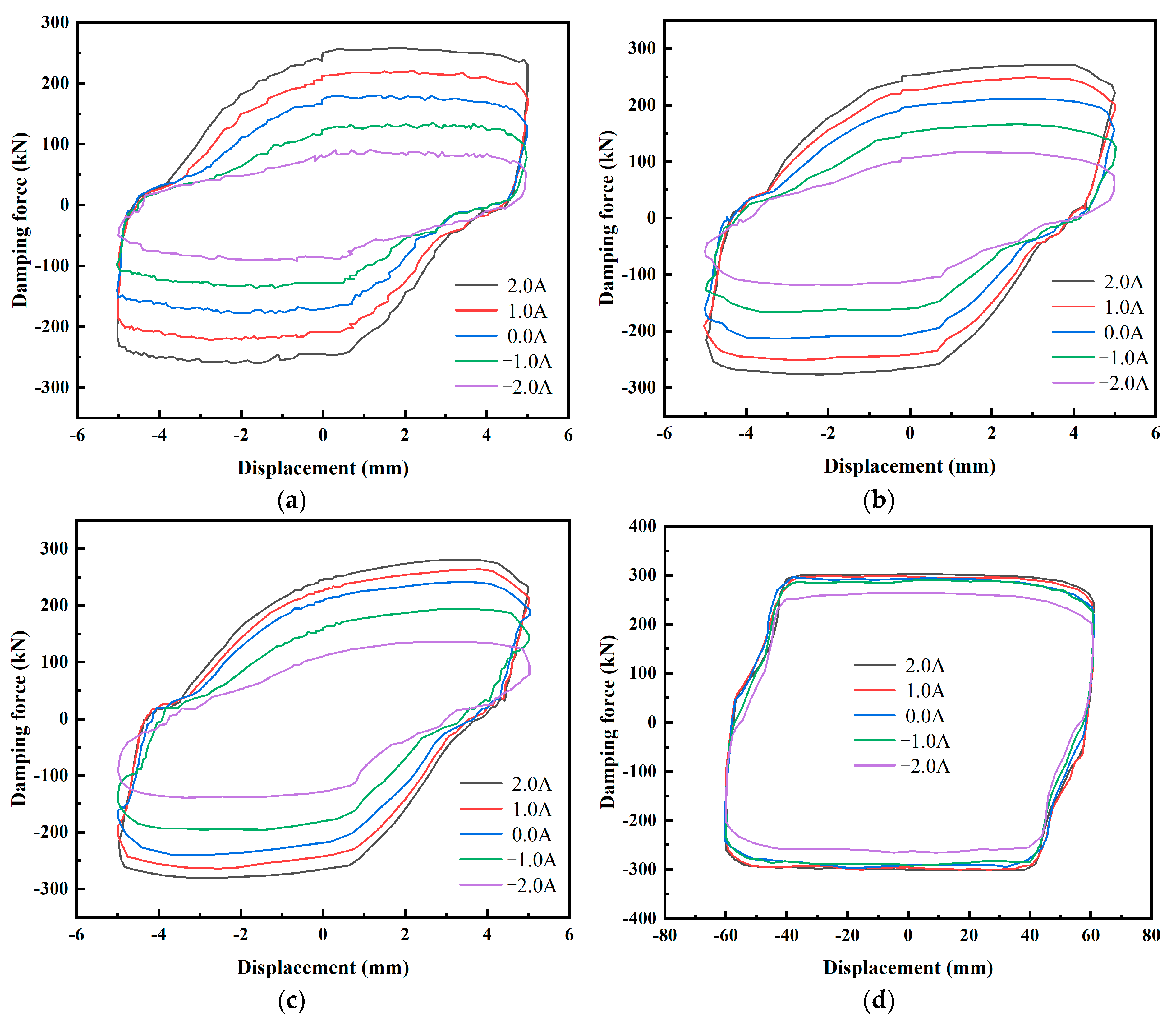
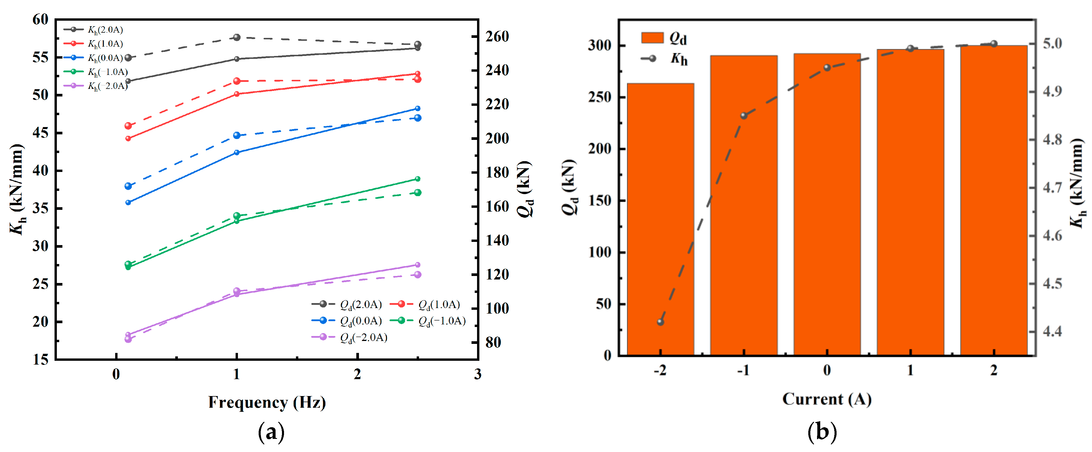
The self-decoupling MR damper can achieve a maximum damping force of 281.5 kN at a small displacement of 5 mm, with an applied frequency of 2.5 Hz and an input current of 2.0 A. Additionally, the highest factor of adjustability of the damping force for the self-decoupling MR damper reaches 3.34 when the current ranges from −2.0 A to 2.0 A, with an applied frequency of 0.1 Hz. Furthermore, the self-decoupling MR damper exhibits a maximum damping force of 300 kN under a large displacement of 60 mm, which aligns with the measurement limit of the testing apparatus. The values of the calculated dynamic parameters, such as equivalent stiffness Kh and yield force Qd, can be enhanced by both the input current and the applied frequency.
(3)
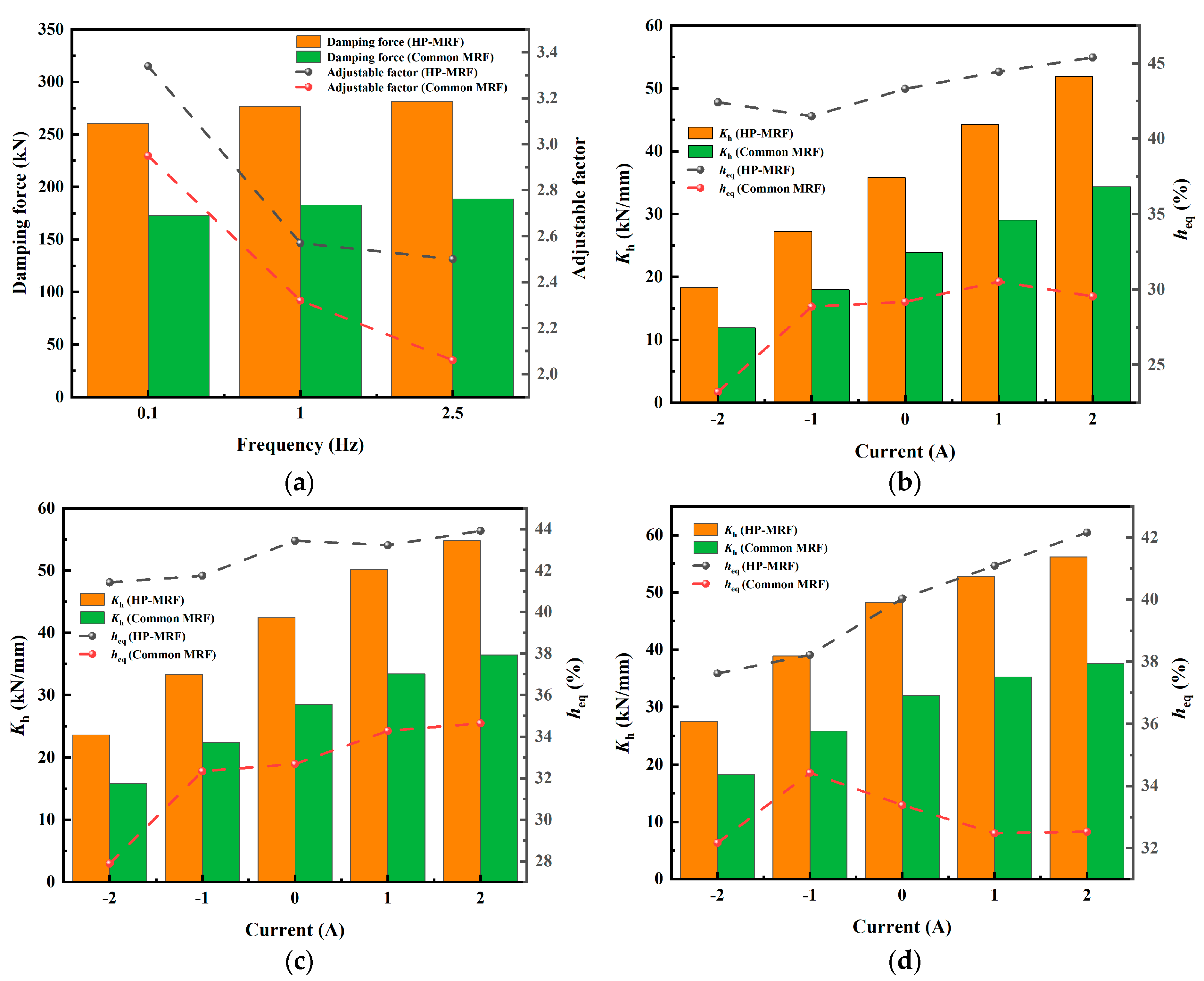
Compared to the prior investigation of a self-decoupling MR damper utilizing a common MRF, the damping force may be increased by a maximum of 93.9 kN, and the adjustable range can also be enlarged. Furthermore, the computed dynamic parameters, including Kh and the equivalent damping ratio heq, are improved, indicating the energy consumption capacity of the self-decoupling MR damper is enhanced with the HP-MRF.

Author Contributions

Methodology, F.G. and Z.M.; Formal analysis, F.G.; Investigation, F.G., H.C. and X.H.; Data curation, F.G.; Writing—original draft, F.G.; Writing—review & editing, F.G.; Supervision, Z.M. and X.L.; Project administration, C.D.; Funding acquisition, F.G., H.C., X.H., C.D., Z.M. and X.L. All authors have read and agreed to the published version of the manuscript.

Funding

This research was funded by Anhui Province University Research Project (2024AH050128), Jiangsu Province Key R&D Project (Grant no. BE2022162), Nature Science Research Project of Anhui province (Grant no. 2308085QD124), Housing Urban and Rural Construction Science and Technology Project of Anhui province (Grant no. 2023YF061, and 2023-YF060), National College Students’ innovation and en-trepreneurship training program (Grant no. 202310363113), Wuhu scientific and technological project (Grant no. 2024kj025, 2023yf088 and 2024kj032), and the Research Start-up Fund Project of Ningbo University of Technology (Grant no. 2023KQ031).

Institutional Review Board Statement

Not applicable.

Informed Consent Statement

Not applicable.

Data Availability Statement

The original contributions presented in this study are included in the article. Further inquiries can be directed to the corresponding authors.

Conflicts of Interest

The authors declare that they have no known competing financial interests or personal relationships that could have appeared to influence the work reported in this paper.

References

  1. Han, W.J.; Wang, G.P.; Yang, F.F. Magnetite/copolymer nanosphere added soft-magnetic carbonyl iron based magnetorheological fluid and its damping performance. IEEE Trans. Magn. 2023, 59, 1–5. [Google Scholar]
  2. Aralikatti, S.S.; Puneet, N.P.; Kumar, H. Determining the optimal composition of magnetorheological fluid for a short-stroke magnetorheological damper. Sadhana 2023, 48, 1–17. [Google Scholar] [CrossRef]
  3. Moreno-Mateos, M.A.; Danas, K.; Garcia-Gonzalez, D. Influence of magnetic boundary conditions on the quantitative modelling of magnetorheological elastomers. Mech. Mater. 2023, 184, 104742. [Google Scholar] [CrossRef]
  4. Zhang, L.Y.; Luo, Y.P.; Ren, H.J.; Wang, Y.; Gu, Z. Microscopic modeling of magnetorheological fluids containing spherical and ellipsoidal ferromagnetic particles. J. Magn. Magn. Mater. 2023, 586, 171204. [Google Scholar] [CrossRef]
  5. Xin, D.K.; Nie, S.L.; Ji, H.; Fang-long, Y. Characteristics, optimal design, and performance analyses of MRF damper. Shock. Vib. 2018, 2018, 6454932. [Google Scholar]
  6. Kariganaur, A.K.; Kumar, H.; Arun, M. Effect of temperature on sedimentation stability and flow characteristics of magnetorheological fluids with damper as the performance analyser. J. Magn. Magn. Mater. 2022, 555, 169342. [Google Scholar] [CrossRef]
  7. Desai, R.M.; Acharya, S.; Jamadar, M.-E.; Kumar, H.; Joladarashi, S.; Sekaran, S.R. Synthesis of magnetorheological fluid and its application in a twin-tube valve mode automotive damper. Proc. Inst. Mech. Eng. Part L J. Mater. Des. Appl. 2020, 234, 1001–1016. [Google Scholar] [CrossRef]
  8. Liu, X.H.; Hu, H.N.; Wang, J.H.; Wu, Y.; Xu, B.; Pu, M.L. Effect of nano-Fe3O4 on normal force of magnetorheological Fluid. Mater. Sci. Eng. Technol. 2022, 53, 698–704. [Google Scholar] [CrossRef]
  9. Ruan, X.H.; Xuan, S.H.; Zhao, J.; Bian, H.; Gong, X. Mechanical performance of a novel magnetorheological fluid damper based on squeeze-valve bi-mode of MRF. Smart Mater. Struct. 2020, 29, 055018. [Google Scholar] [CrossRef]
  10. Nie, S.L.; Xin, D.K.; Ji, H.; Yin, F.L. Optimization and performance analysis of magnetorheological fluid damper considering different piston configurations. J. Intell. Mater. Syst. Struct. 2019, 30, 764–777. [Google Scholar] [CrossRef]
  11. Dong, L.L.; Zhao, R.G.; Luo, B.M.; Han, Y. Design of a new damper based on magnetorheological fluids. Int. J. Appl. Electromagn. Mech. 2019, 59, 357–366. [Google Scholar] [CrossRef]
  12. Wang, C.L.; Wu, L.J.; Wei, X.Q.; Zeng, Q.L. New magneto-inducible magnetorheological damper. J. Vib. Shock. 2024, 43, 248–259. [Google Scholar]
  13. Zhao, J.; Gao, N.; Li, X.P.; Lei, B.B.; Zhao, Y. Experimental and calculation model analysis on hysteresis properties of magnetorheological damper. J. Zhengzhou Univ. 2023, 44, 91–98. [Google Scholar]
  14. Cha, Y.-J.; Agrawal, A.K.; Phillips, B.M.; Spencer, B.F. Direct performance-based design with 200kN MR dampers using multi-objective cost effective optimization for steel MRFs. Eng. Struct. 2014, 71, 60–72. [Google Scholar] [CrossRef]
  15. Yu, G.J.; Zhu, S.J.; Du, C.B.; Wang, L.Y.; Huang, J.C. Design and Performance Test of a Magnetic Rate Controlled Stage Damper. Front. Mater. 2021, 8, 640316. [Google Scholar] [CrossRef]
  16. Archakam, P.K.; Muthuswamy, S. Modelling and simulation of four-stage collision energy absorption system based on magneto rheological absorber. Int. J. Mech. Mater. Des. 2022, 19, 49–72. [Google Scholar] [CrossRef]
  17. Li, G.; Gan, Y.; Liu, Q.; Xu, H.; Chen, D.; Zhong, L.; Deng, J.; Hu, G. Performance analysis of vehicle magnetorheological semi-active air suspension based on S-QFSMC control. Front. Mater. 2024, 11, 1358319. [Google Scholar] [CrossRef]
  18. Wang, C.L.; Zhang, J.W.; Liu, G.M.; Shang, H.; Wei, X. Design and performance analysis of a double-outlet-rod magnetorheological damper for impact load. Machines 2022, 10, 1099. [Google Scholar] [CrossRef]
  19. Yarali, E.; Mohammadi, A.; Mafakheri, S.; Baghani, M.; Adibi, H. Mathematical modeling and experimental evaluation of a prototype double-tube Magnetorheological damper. SN Appl. Sci. 2019, 1, 1341. [Google Scholar] [CrossRef]
  20. Li, J.Q.; Qin, C.G.; Guo, S.J.; Wang, J. Magnetic circuit design and performance analysis of a rotary magnetorheological damper with new structure. In Proceedings of the 2017 IEEE International Conference on Cybernetics and Intelligent Systems (CIS) and IEEE Conference on Robotics, Automation and Mechatronics (RAM), Ningbo, China, 19–21 November 2017; pp. 524–529. [Google Scholar]
  21. Zhao, W.; Li, B.; Tian, W.; Liu, P.; Liao, W. Magnetorheological elastomer absorber-based chatter suppression in robotic milling. Robot. Comput. Manuf. 2024, 88, 102740. [Google Scholar] [CrossRef]
  22. Gurubasavaraju, T.M.; Muralidhar Singh, M. Magnetohydrodynamics analysis of magnetorheological fluid damper. J. Mech. Eng. Sci. 2023, 17, 9453–9462. [Google Scholar]
  23. Yang, X.L.; Zhu, J.H.; Song, Y.Y.; Li, Y. Design and experimental research of stepped bypass magnetorheological damper. J. Intell. Mater. Syst. Struct. 2023, 34, 1527–1547. [Google Scholar] [CrossRef]
  24. Wang, Y.J.; Wang, M.; Gao, P.X.; Yu, T.; Xi, J. Discrete fiber skeleton strengthened magnetorheological grease and a novel H-B model based on fiber parameters. AIP Adv. 2024, 14, 035212. [Google Scholar] [CrossRef]
  25. Ma, T.; Bi, F.; Wang, X.; Tian, C.; Lin, J.; Wang, J.; Pang, G. Optimized Fuzzy Skyhook Control for Semi-Active Vehicle Suspension with New Inverse Model of Magnetorheological Fluid Damper. Energies 2021, 14, 1674. [Google Scholar] [CrossRef]
  26. Zhao, D.; Zhao, J.B.; Zhao, Z.H.; Liu, Y.; Liu, S.; Wang, S. Design and experimental study of the porous foam metal magnetorheological fluid damper based on built-in multi-pole magnetic core. J. Intell. Mater. Syst. Struct. 2020, 31, 687–703. [Google Scholar] [CrossRef]
  27. Yan, W.; Huina, H.; Wang, X.; Xu, B.; He, Y.; Liu, X. Semi-active control of metal foam magnetorheological damper. Mater. Sci. Eng. Technol. 2021, 52, 1355–1362. [Google Scholar] [CrossRef]
  28. Ansari, M.A.; Meher, P.K.; Bisoi, A.; Biswas, A. Augmentation of damping force by modifying the geometrical shape of the MR damper. J. Braz. Soc. Mech. Sci. Eng. 2023, 45, 1–13. [Google Scholar] [CrossRef]
  29. Tan, A.S.; Sattel, T.; Subianto, R. A Novel Design Concept of a Magnetorheological Fluid-Based Damper Utilizing the Porous Medium for Implementation in Small-Scale Applications. Fluids 2023, 8, 203. [Google Scholar] [CrossRef]
  30. Hu, D.; Long, H.T.; Lu, J.B.; Liang, W.; Li, H.; Yan, Q. Preparation and performance study of microporous magnetorheological elastomer polishing pad. Mater. Today Commun. 2024, 41, 110980. [Google Scholar]
  31. Xu, C.; Peng, X.; Hu, H.; Liu, J.; Li, H.; Luo, T.; Lai, T. Nano-Precision Processing of NiP Coating by Magnetorheological Finishing. Nanomaterials 2023, 13, 2118. [Google Scholar] [CrossRef]
  32. Sarath, S.; Paul, P.S.; Lawrance, G. Characterization and performance analysis of magnetorheological foam damper for vibration control during boring process. Multiscale Multidiscip. Model. Exp. Des. 2023, 7, 837–854. [Google Scholar] [CrossRef]
  33. Chen, S.; Weng, Y.; Yao, B. Material removal model for magnetorheological polishing considering shear thinning and experimental verification. Mater. Today Commun. 2024, 38, 108475. [Google Scholar] [CrossRef]
  34. Bi, C.; Ji, A.; Bi, E.; Wang, H.; Zhu, W.; Lin, W. Investigation on roller-type ultrasonic assisted magnetorheological finishing for biomedical small and complex surface of titanium alloy. Mater. Today Commun. 2024, 38, 107702. [Google Scholar] [CrossRef]
  35. Chen, W.Q.; Du, C.B.; Wan, F.X. Effect of surfactant and thixotropic agent on the sedimentation stability of magneto-rheological fluid. J. Magn. Mater. Devices 2010, 41, 55–57+65. [Google Scholar]
  36. Yu, G.; Du, C.; Sun, T. Thermodynamic Behaviors of a Kind of Self-Decoupling Magnetorheological Damper. Shock. Vib. 2015, 2015, 502747. [Google Scholar] [CrossRef]
  37. Jolly, M.R.; Carlson, J.D.; Muñoz, B.C. A model of the behaviour of magnetorheological materials. Smart Mater. Struct. 1996, 5, 607–614. [Google Scholar] [CrossRef]
  38. Shen, Y.; Golnaraghi, M.F.; Heppler, G.R. Experimental Research and Modeling of Magnetorheological Elastomers. J. Intell. Mater. Syst. Struct. 2004, 15, 27–35. [Google Scholar] [CrossRef]
  39. Available online: https://www.lord.com (accessed on 2 June 2025).
  40. Han, M.; Liu, X.H.; Du, H.K.; Jiang, J.W.; Yang, J.C. Experimental research on shearing properties of small lead-core rubber bearings. J. Vib. Eng. 2024, 37, 326–335. [Google Scholar]
Figure 1. Process of HP-MRF preparation. (a) The procedure of treating CIP; (b) HP-MRF based on a composite carrier.
Applsci 15 06305 g001
Figure 2. Characterization of treated CIPs and HP-MRFs. (a) D8 Advance X-ray diffractometer and particle size distribution testing device; (b) particle size of treated CIPs with ball milling time; (c) XRD patterns of original and treated CIPs; (d) MCR302 rotational rheometer system.
Applsci 15 06305 g002
Figure 3. Production and evaluation of the self-decoupling MR damper. (a) Structure and the magnetic circuit in the self-decoupling MR damper; (b) magnetic induction in the damping channel of the main piston; (c) experimental setup of the self-decoupling MR damper.
Applsci 15 06305 g003
Figure 4. The relationship between shear stress and magnetic flux density of single-graded HP-MRFs.
Applsci 15 06305 g004
Figure 5. The relationship between shear stress and magnetic flux density of single-graded and double graded HP-MRFs.
Applsci 15 06305 g005
Figure 6. The relationship between shear stress and magnetic flux density of double-graded HP-MRFs. (a) The influence of different particle sizes of sub-micron CIPs in double-graded HP-MRFs; (b) the influence of different particle contents of sub-micron CIPs in double-graded HP-MRFs.
Applsci 15 06305 g006
Figure 7. The force–displacement characteristics of the self-decoupling MR damper with current input of −2.0 A, −1.0 A, 0 A, 1.0 A, and 2.0 A at (a) a small displacement of 5 mm and applied frequency of 0.1 Hz; (b) a small displacement of 5 mm and applied frequency of 1.0 Hz; (c) a small displacement of 5 mm and applied frequency of 2.5 Hz; (d) a large displacement of 60 mm and applied frequency of 0.1 Hz.
Applsci 15 06305 g007
Figure 8. Determination of the shear properties of the self-decoupling MR damper.
Applsci 15 06305 g008
Figure 9. Calculated dynamic parameters of the self-decoupling MR damper. (a) Variation in equivalent stiffness Kh and yield force Qd with frequency under different input currents and small displacement of 5 mm; (b) variation in Kh and Qd with input currents and a large displacement of 60 mm.
Applsci 15 06305 g009
Figure 10. Comparison of the dynamic mechanical properties for the self-decoupling MR damper filled with the common MRF and the HP-MRF at small displacement of 5mm. (a) Comparison of damping force and adjustable factor with different frequencies; (b) comparison of equivalent stiffness Kh and equivalent damping ratio heq at 0.1 Hz; (c) comparison of equivalent stiffness Kh and equivalent damping ratio heq at 1.0 Hz; (d) comparison of equivalent stiffness Kh and equivalent damping ratio heq at 2.5 Hz.
Applsci 15 06305 g010
Table 1. Composition of HP-MRF samples with different CIP gradations.
SampleCIP GradationSampleCIP Gradation
HP-MRF-1100% not milledHP-MRF-7100% milled for 60 h
HP-MRF-2100% milled for 6 hHP-MRF-8100% milled for 72 h
HP-MRF-3100% milled for 12 hHP-MRF-990% not milled +
10% milled for 12 h
HP-MRF-4100% milled for 24 hHP-MRF-1090% not milled +
10% milled for 24 h
HP-MRF-5100% milled for 36 hHP-MRF-1190% not milled +
10% milled for 60 h
HP-MRF-6100% milled for 48 hHP-MRF-1292% not milled +
8% milled for 24 h
Table 2. Dynamic parameters of the self-decoupling MR damper.
Displacement
(mm)
Frequency
(Hz)
Current
(A)
Kh
(kN/mm)
Kd
(kN/mm)
Qd
(kN)
heq
(%)
5.00.12.051.852.34247.5545.39
5.00.11.044.262.77207.4544.44
5.00.10.035.801.39172.0543.31
5.00.1−1.027.212.0126.0541.49
5.00.1−2.018.311.9182.0042.41
5.01.02.054.782.89259.4543.91
5.01.01.050.143.38233.8043.22
5.01.00.042.422.05201.8543.44
5.01.0−1.033.332.41154.6041.75
5.01.0−2.023.631.56110.3541.43
5.02.52.056.195.13255.3042.16
5.02.51.052.845.87234.8541.09
5.02.50.048.245.81212.1540.03
5.02.5−1.038.935.28168.2538.22
5.02.5−2.027.563.55120.0537.62
60.00.12.05.000.00300.0057.29
60.00.11.04.990.05296.4057.12
60.00.10.04.950.08292.1056.12
60.00.1−1.04.850.02290.3055.78
60.00.1−2.04.420.03263.4555.03
Table 3. Maximum damping force comparison with state-of-the-art MR dampers.
ReferenceMRF TypeParticle Grading of CIPMaximum Damping Force (kN)
Proposed workHP-MRFDouble300
Ref. [12]Conventional MRFSingle97.9
Ref. [13]Conventional MRFSingle100
Ref. [14]Conventional MRFSingle200
Ref. [15]MRF with silicaSingle250.2
Disclaimer/Publisher’s Note: The statements, opinions and data contained in all publications are solely those of the individual author(s) and contributor(s) and not of MDPI and/or the editor(s). MDPI and/or the editor(s) disclaim responsibility for any injury to people or property resulting from any ideas, methods, instructions or products referred to in the content.

