
Design Features of a Removable Module Intended for Securing Containers When Transported in an Open Wagon

 , ,
, ,  , and
, and
Abstract
1. Introduction
- To optimize the cross-section parameters of the beams of the removable module frame according to the criterion of minimum material consumption;
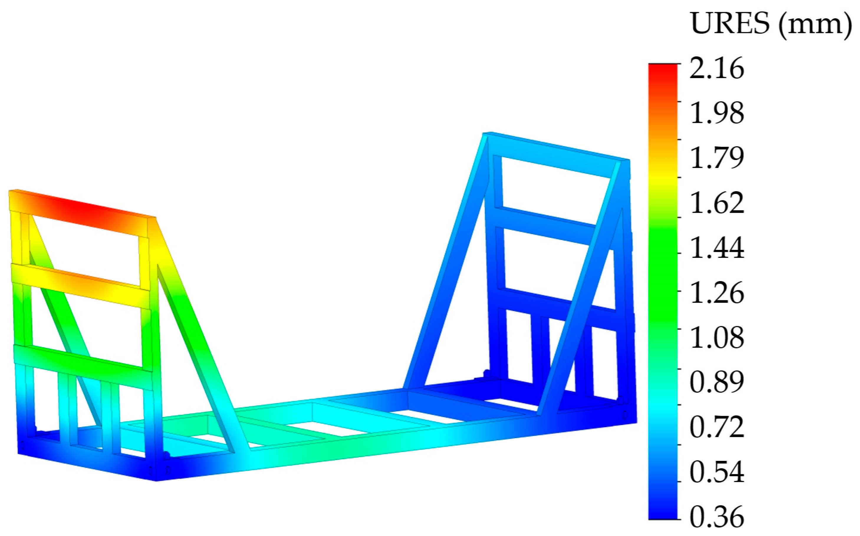
- To calculate the strength of the removable module;
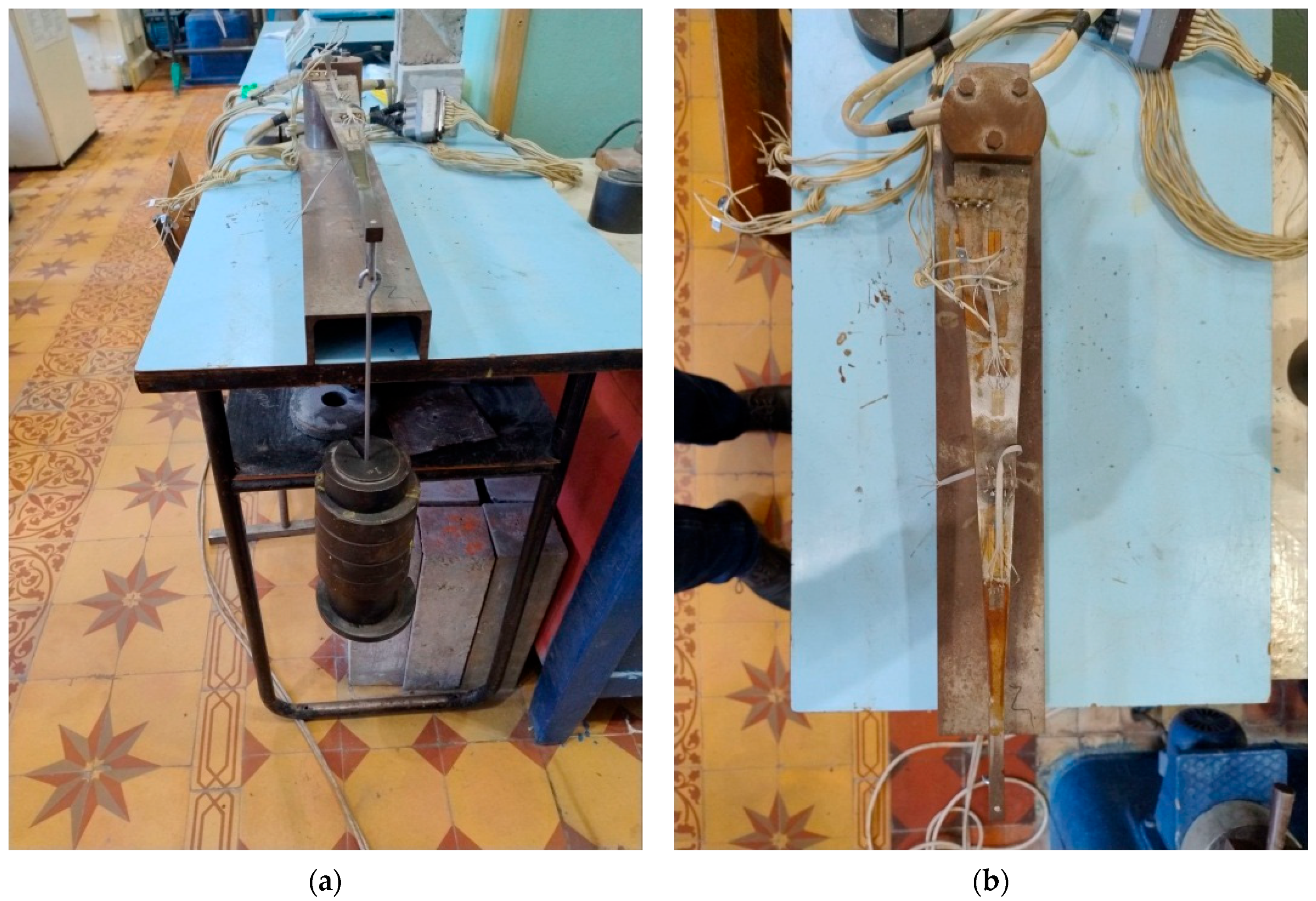
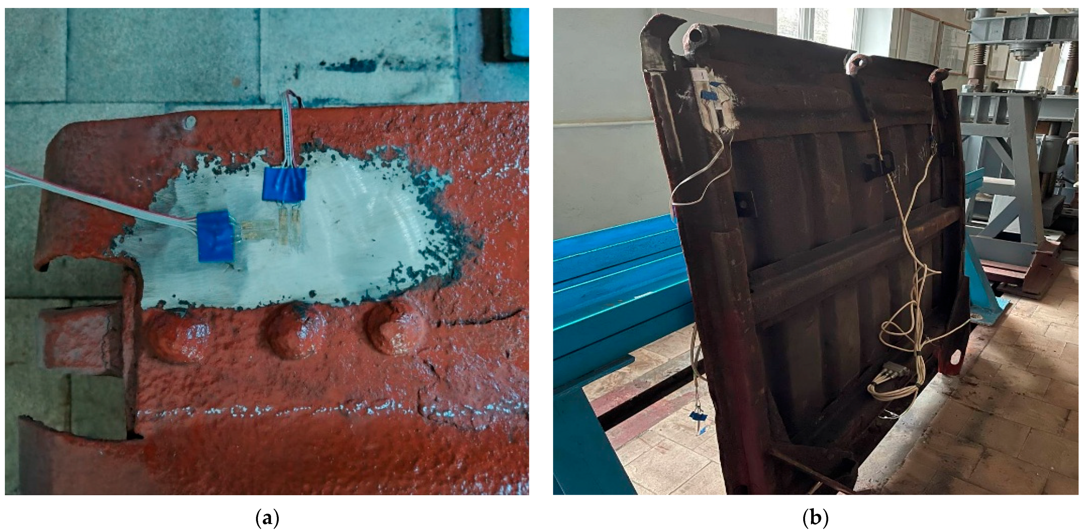
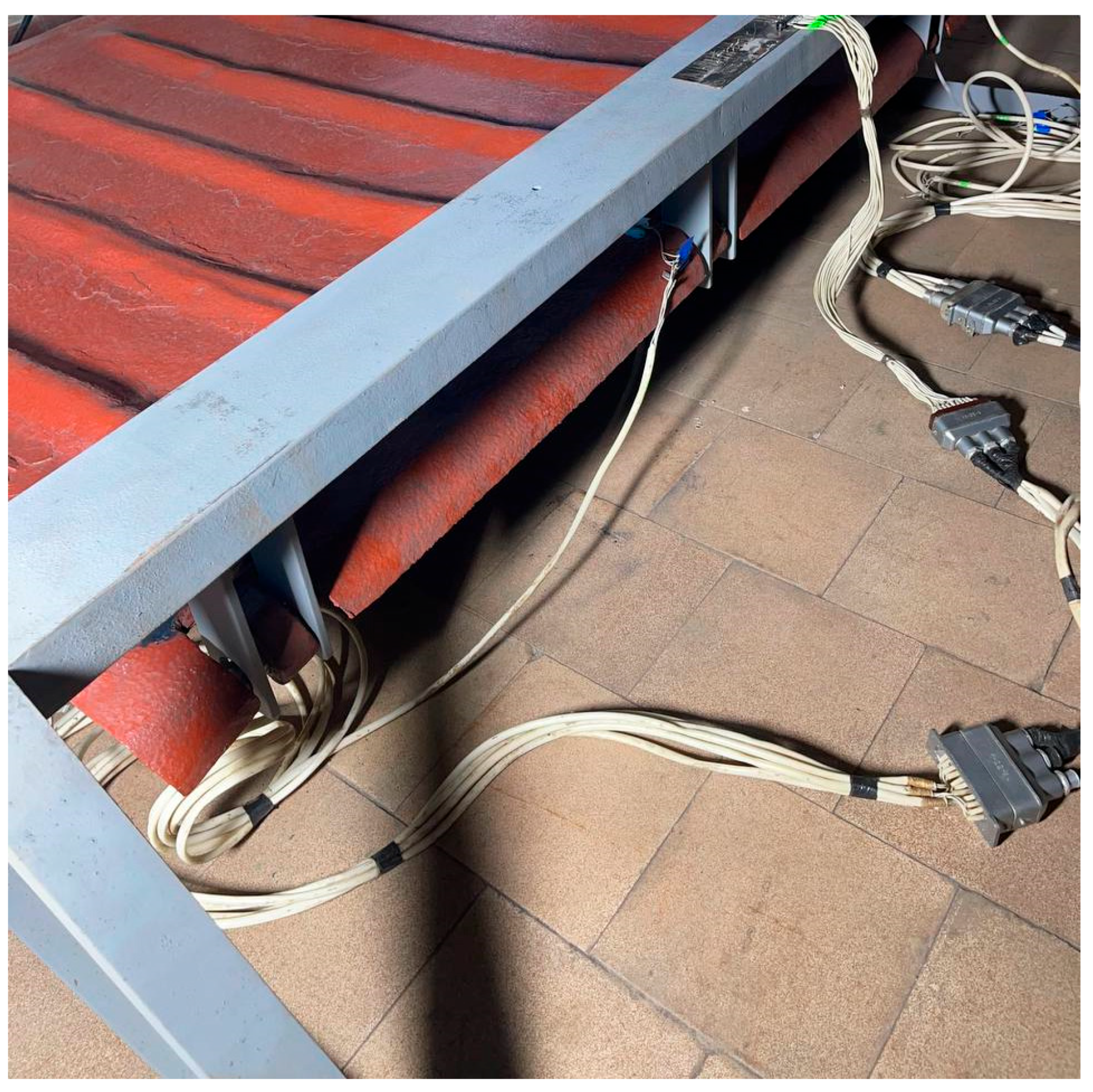
- To conduct an experimental study of the strength of an open wagon hatch cover under load from the removable module.
2. Materials and Methods
3. Results
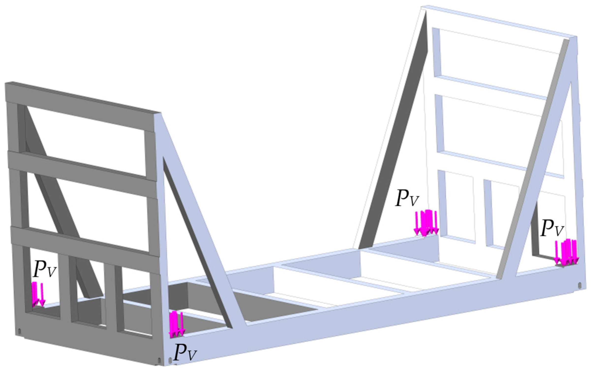
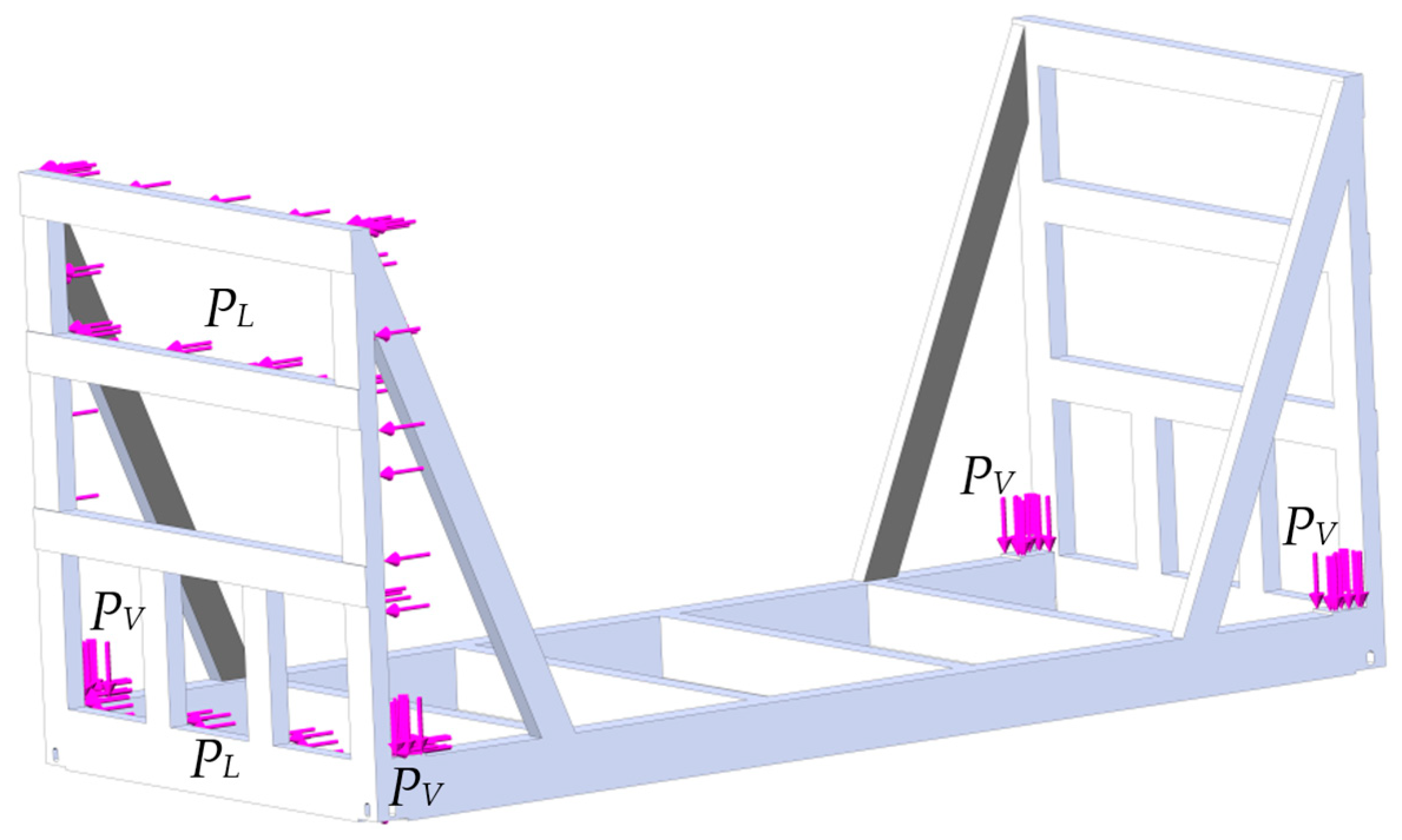
- An action of the vertical load PV (Figure 9);
4. Discussion
5. Conclusions
6. Patents
- Freight unit: Patent 156991 Ukraine, MPK B65D 88/12 (2006.01); u202400568. Application 2 February 2024; Publication 28 August 2024. Bulletin No. 35.
- Open wagon for container transportation. Patent 157214 Ukraine, MPK (2024.01) B61F 1/00 B61D 3/00; u202400795. Application 16 February 2024; Publication 18 September 2024. Bulletin No. 38.
- Modular cargo unit: Patent 157156 Ukraine, MPK B65D 88/12 (2006.01); u202400565. Application 02 February 2024; Publication 11 September 2024. Bulletin No. 37.
Author Contributions
Funding
Institutional Review Board Statement
Informed Consent Statement
Data Availability Statement
Conflicts of Interest
References
- Kučera, P.; Heřmánková, A. The use of automation in rail transport to ensure interchanges in regional passenger transport. Commun.-Sci. Lett. Univ. Zilina 2024, 26, D82–D91. [Google Scholar] [CrossRef]
- Heřmánková, A.; Kučera, P. The importance of rail transport for transport services in peripheral areas. LOGI-Sci. J. Transp. Logist. 2024, 15, 13–24. [Google Scholar] [CrossRef]
- Akgun, N.; Campisi, T.; Talha Sunar, M. Generalized ordered logit model with testing assumptions: A case study of using urban light rail in Bursa. Commun.-Sci. Lett. Univ. Zilina 2024, 26, D38–D51. [Google Scholar] [CrossRef]
- Mindur, M.; Mindur, L. The influence of the selected international organizations on the development of transport. Sci. J. Silesian Univ. Technol. Ser. Transp. 2023, 119, 171–187. [Google Scholar] [CrossRef]
- Melnik, R.; Sowinski, B. Application of the rail Vehicle’s monitoring system in the process of suspension condition assessment. Commun.-Sci. Lett. Univ. Žilina 2013, 15, 3–8. [Google Scholar] [CrossRef]
- Opala, M.; Korzeb, J.; Koziak, S.; Melnik, R. Evaluation of stress and fatigue of a rail vehicle suspension component. Energies 2021, 14, 3410. [Google Scholar] [CrossRef]
- Hlavatý, J.; Ližbetin, J.; Fázik, J. The role of logistics in the management of the railway rolling stock life cycle. LOGI-Sci. J. Transp. Logist. 2023, 14, 298–308. [Google Scholar] [CrossRef]
- Fischer, S. Investigation of the settlement behavior of ballasted railway tracks due to dynamic loading. Spectr. Mech. Eng. Oper. Res. 2025, 2, 24–46. [Google Scholar] [CrossRef]
- Kruhan, D.; Kovalskyi, D. Quasi-static methods for determining the calculated wheel load on the railway track. Acta Tech. Jaurinensis 2025, 18, 38–45. [Google Scholar] [CrossRef]
- Ezsias, L.; Kozma, K.; Tompa, R.; Fischer, S. Crushed stone supply challenges for infrastructure development in Hungary. Nauk. Visnyk Natsionalnoho Hirnychoho Universytetu 2024, 6, 28–37. [Google Scholar] [CrossRef]
- Fischer, S.; Harangozó, D.; Németh, D.; Kocsis, B.; Sysyn, M.; Kurhan, D.; Brautigam, A. Investigation of heat-affected zones of thermite rail welding. Facta Univ. Ser. Mech. Eng. 2024, 22, 689–710. [Google Scholar] [CrossRef]
- Jover, V.; Fischer, S. Statistical analysis of track geometry parameters on tramway line No. 1 in Budapest. Balt. J. Road Bridge Eng. 2022, 17, 75–106. [Google Scholar] [CrossRef]
- Juricka, M.; Fojtl, L.; Rusnáková, S.; Juřičková, E. Acoustic characteristics of composite structures used in train. Manuf. Technol. 2020, 20, 335–341. [Google Scholar] [CrossRef]
- Fischer, S.; Kocsis Szürke, S. Detection process of energy loss in electric railway vehicles. Facta Univ. Ser. Mech. Eng. 2023, 21, 81–99. [Google Scholar] [CrossRef]
- Tomaschek, T.A.; Selmeczy, A.M. Mobility data for a safer and greener transport. Acta Tech. Jaurinensis 2023, 16, 129–142. [Google Scholar] [CrossRef]
- Kostrzewski, M.; Abdelatty, Y.; Eliwa, A.; Nader, M. Analysis of modern vs. conventional development technologies in transportation—The case study of a last-mile delivery process. Sensors 2022, 22, 9858. [Google Scholar] [CrossRef] [PubMed]
- Petrović, A.D.; Banić, M.; Simonović, M.; Stamenković, D.; Miltenović, A.; Adamović, G.; Rangelov, D. Integration of computer vision and convolutional neural networks in the system for detection of rail track and signals on the railway. Appl. Sci. 2022, 12, 6045. [Google Scholar] [CrossRef]
- Rosić, S.; Stamenković, D.; Banić, M.; Simonović, M.; Ristić-Durrant, D.; Ulianov, C. Analysis of the safety level of obstacle detection in autonomous railway vehicles. Acta Polytech. Hung. 2022, 19, 187–205. [Google Scholar] [CrossRef]
- Zhang, D.; Wang, S.-M.; Tang, Y.-Y.; Ni, Y.-Q.; Guo, J.-W.; Peng, Q.-Y. A novel method for evaluating load restraint assemblies to ensure the safety of railway freight transportation. Sci. Rep. 2024, 14, 4612. [Google Scholar] [CrossRef]
- Matej, J.; Seńko, J.; Caban, J.; Szyca, M.; Gołȩbiewski, H. Influence of unsupported sleepers on flange climb derailment of two freight wagons. Open Eng. 2024, 14, 20220544. [Google Scholar] [CrossRef]
- Gnap, J.; Senko, Š.; Kostrzewski, M.; Brídziková, M.; Cződörová, R.; Říha, Z. Research on the relationship between transport infrastructure and performance in rail and road freight transport—A case study of Japan and selected European countries. Sustainability 2021, 13, 6654. [Google Scholar] [CrossRef]
- Namayanja, Z.; Nkundineza, C.; Zewdie, B.M. Analyzing the impact of curved tracks on wheel flange thickness reduction in railway systems. Open Eng. 2024, 14, 20240089. [Google Scholar] [CrossRef]
- Abdullayev, S.; Bakyt, G.; Kamzina, A.; Sarsanbekov, K.; Abdullayeva, A. Interaction of the TE33A diesel locomotive and the railway track on curved section with radius 290m. Commun.-Sci. Lett. Univ. Žilina 2023, 25, B315–B326. [Google Scholar] [CrossRef]
- Mikhailov, E.; Semenov, S.; Sapronova, S.; Tkachenko, V. On the issue of wheel flange sliding along the rail. In Proceedings of the 11th International Conference Transbaltica, Vilnius, Lithuania, 2–3 May 2019. [Google Scholar]
- Nozhenko, V.; Kovtanets, M.; Sergienko, O.; Prosvirova, O.; Kovtanets, T.; Boyko, G.; Semenov, S. Method for Determining the Linear Velocity of a Locomotive Development. In Proceedings of the 25th International Scientific Conference Transport Means 2021, Kaunas, Lithuania, 6–8 October 2021. [Google Scholar]
- Alic, D.; Miltenovic, A.; Banic, M.; Zafra, R.V. Numerical investigation of large vehicle aerodynamics under the influence of crosswind. Spectr. Mech. Eng. Oper. Res. 2025, 2, 13–23. [Google Scholar] [CrossRef]
- Wan, M.; Kuang, H.; Yu, Y.; Zhang, R. Evaluation of the competitiveness of the container multimodal port hub. Sci. Rep. 2022, 12, 19334. [Google Scholar] [CrossRef]
- Nehring, K.; Klodawski, M.; Jachimowski, R.; Klimek, P.; Vasek, R. Simulation analysis of the impact of container wagon pin configuration on the train loading time in the intermodal terminal. Arch. Transp. 2021, 60, 155–169. [Google Scholar] [CrossRef]
- Jachimowski, R.; Kłodawski, M. The impact of container yard layout on the cargo handling time of external transport vehicles in an intermodal terminal. Arch. Transp. 2025, 73, 179–193. [Google Scholar] [CrossRef]
- Nehring, K.; Lasota, M.; Zabielska, A.; Jachimovski, R. A multifaceted approach to assessing intermodal transport. Sci. J. Silesian Univ. Technol. Ser. Transp. 2023, 121, 141–165. [Google Scholar] [CrossRef]
- Szczepański, E.; Gołȩbiowski, P.; Kondracka, B. Evaluation of the technological process of wagon processing at shunting stations using the simulation model. Sci. J. Silesian Univ. Technol. Ser. Transp. 2023, 120, 249–267. [Google Scholar] [CrossRef]
- Berescu, C.; Fratila, C.; Axinte, T.; Diaconu, M.; Cojocaru, R. The mechanism’s study of fixing a container on a freight wagon type Rgs. In Proceedings of the ModTech International Conference—Modern Technologies in Industrial Engineering VIII, Iasi, Romania, 23–27 June 2020. [Google Scholar] [CrossRef]
- Reidemeister, O.H.; Kalashnyk, V.O.; Shykunov, O.A. Modernization as a way to improve the use of universal cars. Sci. Transp. Prog. 2016, 2, 148–156. [Google Scholar] [CrossRef]
- Shaposhnyk, V.; Shykunov, O.; Reidemeister, A.; Leontii, M.; Potapenko, O. Determining the possibility of using removable equipment for transporting 20- and 40-feet-long containers on an universal platform wagon. East.-Eur. J. Enterp. Technol. 2021, 1, 14–21. [Google Scholar] [CrossRef]
- Gerlici, J.; Lovska, A.; Vatulia, G.; Pavliuchenkov, M.; Kravchenko, O.; Solcansky, S. Situational adaptation of the open wagon body to container transportation. Appl. Sci. 2023, 13, 8605. [Google Scholar] [CrossRef]
- Laaers L04A|2×2-Axle Wagon, Series Laadgrs—Open Flat Car Carrier and Container Twin Wagon. Available online: https://www.greenbrier-europe.com (accessed on 19 March 2025).
- Lovska, A.; Stanovskyi, O.; Zharova, O.; Naumenko, Y.; Pelypenko, Y. Identifying patterns in loading a gondola car body with reinforcing belts in the structure of side walls. East.-Eur. J. Enterp. Technol. 2024, 3/7, 17–25. [Google Scholar] [CrossRef]
- Divya Priya, G. Modeling and analysis of twenty tonne heavy duty trolley. Int. J. Innov. Technol. Res. 2014, 2, 1568–1580. [Google Scholar]
- Gerlici, J.; Lovska, A.; Vatulia, G.; Dizo, J.; Blatnicky, M. Research into the strength of the discharge door of an open wagon transporting containers. In Proceedings of the 15th International Scientific Conference on Aeronautics, Automotive, and Railway Engineering and Technologies, BulTrans 2023, Sozopol, Bulgaria, 10–13 September 2023. [Google Scholar] [CrossRef]
- Viznyak, R.; Chepurchenko, I.; Yatsenko, A. Features of identifying operational loads the body of open-top car and ways of improving its design to ensure durability and preservation (In Ukrainian). Collect. Sci. Work. Ukr. State Univ. Railw. Transp. 2016, 159, 91–97. [Google Scholar]
- Kovalenko, V.V. Improvement of the Operation of Gondola Open Box-Type by Improving Their Design and Calculation Methods. Dissertation Ph.D. Thesis, Volodymyr Dahl East Ukrainian National University, Kyiv, Ukraine, 2019. [Google Scholar]
- Fomin, O.; Gorbunov, M.; Kovalenko, V.; Flyakovska, V. Formalized description of structures of the semiconductor floorcrisp (Part 2). Bull. East Ukr. Natl. Univ. Named After Volodymyr Dal 2018, 1, 145–152. [Google Scholar]
- Baranovskyi, D.; Bulakh, M.; Myamlin, S.; Kebal, I. New design of the hatch cover to increase the carrying capacity of the gondola car. Adv. Sci. Technol.-Res. J. 2022, 16, 186–191. [Google Scholar] [CrossRef]
- Šťastniak, P.; Moravčík, M. Freight bogie prototype properties analysis by means of simulation computations. Manuf. Technol. 2017, 17, 27–28. [Google Scholar] [CrossRef]
- Šťastniak, P.; Smetanka, L.; Moravcík, M. Structural analysis of a main construction assemblies of the new wagon prototype type zans. Manuf. Technol. 2018, 18, 510–517. [Google Scholar] [CrossRef]
- Panchenko, S.; Lovska, A.; Muradian, A.; Pelypenko, Y.; Rukavishnykov, P.; Demydiukov, O. Identifying possible ways for adapting an open wagon for transporting containers. East.-Eur. J. Enterp. Technol. 2024, 5/7, 6–14. [Google Scholar] [CrossRef]
- Gerlici, J.; Lovska, A.; Pavliuchenkov, M. Study of the dynamics and strength of the detachable module for long cargoes under asymmetric loading diagrams. Appl. Sci. 2024, 14, 3211. [Google Scholar] [CrossRef]
- Vatulia, G.L.; Lovska, A.O.; Krasnokutskyi, Y.S. Research into the transverse loading of the container with sandwich-panel walls when transported by rail. In Proceedings of the 4th International Conference on Sustainable Futures: Environmental, Technological, Social and Economic Matters, ICSF 2023, Kryvyi Rih, Ukraine, 22–26 May 2023. [Google Scholar] [CrossRef]
- Caban, J.; Nieoczym, A.; Matijošius, J.; Kilikevičius, A.; Drozd, K. Analysis of the construction of the car trailer frame in terms of changing the assembly technology. Sci. J. Silesian Univ. Technol. Ser. Transp. 2024, 124, 47–61. [Google Scholar] [CrossRef]
- Caban, J.; Nieoczym, A.; Krzywonos, L. Strength analysis of subsoiler tooth. Eng. Rural. Dev. 2024, 23, 286–293. [Google Scholar] [CrossRef]
- Goolak, S.; Sapronova, S.; Tkachenko, V.; Riabov, I.; Batrak, Y. Improvement of the Model of Power Losses in the Pulsed Current Traction Motor in an Electric Locomotive. East.-Eur. J. Enterp. Technol. 2020, 6, 38–46. [Google Scholar] [CrossRef]
- Goolak, S.; Tkachenko, V.; Bureika, G.; Vaičiūnas, G. Method of spectral analysis of traction current of AC electric locomotives. Transport 2020, 35, 658–668. [Google Scholar] [CrossRef]
- Goolak, S.; Kyrychenko, M. Thermal Model of the Output Traction Converter of an Electric Locomotive with Induction Motors. Probl. Energeticii Reg. 2022, 3, 1–16. [Google Scholar] [CrossRef]
- Kučera, Ľ.; Patin, B.; Gajdošík, T.; Palenčár, R.; Palenčár, J.; Ujlaky, M. Application of metrological approaches in the design of calibration equipment for verification of float level gauges. Meas. Sci. Rev. 2020, 20, 230–235. [Google Scholar] [CrossRef]
- Lovska, A.; Gerlici, J.; Dizo, J.; Ishchuk, V. The strength of rail vehicles transported by a ferry considering the influence of sea waves on its hull. Sensors 2024, 24, 183. [Google Scholar] [CrossRef]


| Parameters | Initial Value [m] | Average Value [m] | Final Value [m] |
|---|---|---|---|
| t1 | 0.004 | 0.006 | 0.008 |
| t2 | 0.004 | 0.006 | 0.008 |
| b | 0.180 | 0.260 | 0.340 |
| h | 0.180 | 0.240 | 0.300 |
| , xb, xh | –1.000 | 0 | 1.000 |
| Mode No. | [m] | [m] | xb [m] | xh [m] |
|---|---|---|---|---|
| 1 | 1 | 1 | 1 | 1 |
| 2 | 1 | 1 | 1 | −1 |
| 3 | 1 | 1 | −1 | 1 |
| 4 | 1 | 1 | −1 | −1 |
| 5 | 1 | −1 | 1 | 1 |
| 6 | 1 | −1 | 1 | −1 |
| 7 | 1 | −1 | −1 | 1 |
| 8 | 1 | −1 | −1 | −1 |
| 9 | −1 | 1 | 1 | 1 |
| 10 | −1 | 1 | 1 | −1 |
| 11 | −1 | 1 | −1 | 1 |
| 12 | −1 | 1 | −1 | −1 |
| 13 | −1 | −1 | 1 | 1 |
| 14 | −1 | −1 | 1 | −1 |
| 15 | −1 | −1 | −1 | 1 |
| 16 | −1 | −1 | −1 | −1 |
| 17 | 0 | 0 | 0 | 0 |
| 18 | 1 | 0 | 0 | 0 |
| 19 | −1 | 0 | 0 | 0 |
| 20 | 0 | 1 | 0 | 0 |
| 21 | 0 | −1 | 0 | 0 |
| 22 | 0 | 0 | 1 | 0 |
| 23 | 0 | 0 | −1 | 0 |
| 24 | 0 | 0 | 0 | 1 |
| 25 | 0 | 0 | 0 | −1 |
| Mode No. | [m] | [m] | xb [m] | xh [m] |
|---|---|---|---|---|
| 1 | 0.008 | 0.008 | 0.34 | 0.3 |
| 2 | 0.008 | 0.008 | 0.34 | 0.18 |
| 3 | 0.008 | 0.008 | 0.18 | 0.3 |
| 4 | 0.008 | 0.008 | 0.18 | 0.18 |
| 5 | 0.008 | 0.004 | 0.34 | 0.3 |
| 6 | 0.008 | 0.004 | 0.34 | 0.18 |
| 7 | 0.008 | 0.004 | 0.18 | 0.3 |
| 8 | 0.008 | 0.004 | 0.18 | 0.18 |
| 9 | 0.004 | 0.008 | 0.34 | 0.3 |
| 10 | 0.004 | 0.008 | 0.34 | 0.18 |
| 11 | 0.004 | 0.008 | 0.18 | 0.3 |
| 12 | 0.004 | 0.008 | 0.18 | 0.18 |
| 13 | 0.004 | 0.004 | 0.34 | 0.3 |
| 14 | 0.004 | 0.004 | 0.34 | 0.18 |
| 15 | 0.004 | 0.004 | 0.18 | 0.3 |
| 16 | 0.004 | 0.004 | 0.18 | 0.18 |
| 17 | 0.006 | 0.006 | 0.26 | 0.24 |
| 18 | 0.008 | 0.006 | 0.26 | 0.24 |
| 19 | 0.004 | 0.006 | 0.26 | 0.24 |
| 20 | 0.006 | 0.008 | 0.26 | 0.24 |
| 21 | 0.006 | 0.004 | 0.26 | 0.24 |
| 22 | 0.006 | 0.006 | 0.34 | 0.24 |
| 23 | 0.006 | 0.006 | 0.18 | 0.24 |
| 24 | 0.006 | 0.006 | 0.26 | 0.3 |
| 25 | 0.006 | 0.006 | 0.26 | 0.18 |
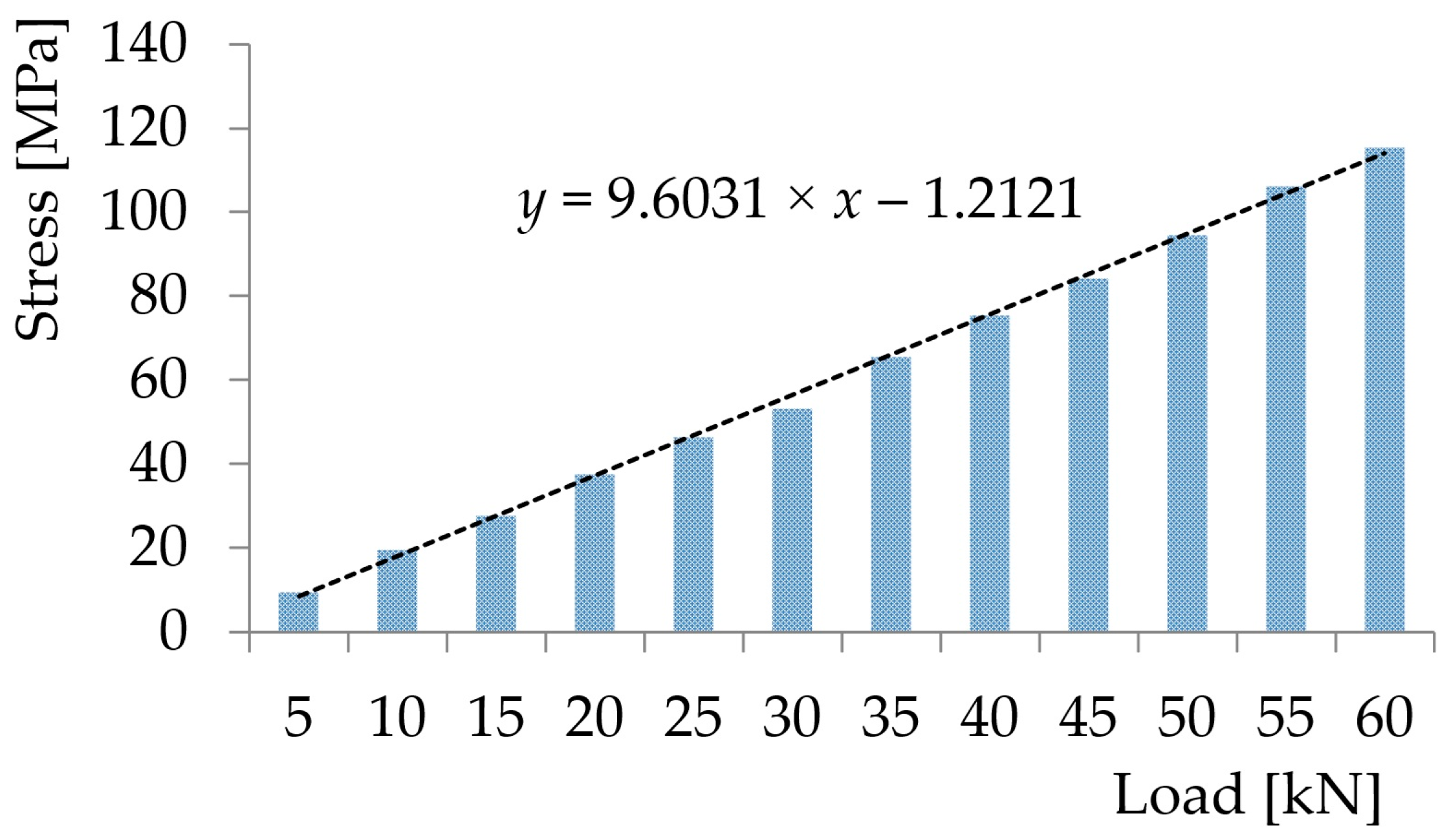
| Load [kN] | Stress [MPa] |
|---|---|
| 5 | 9.4 |
| 10 | 19.5 |
| 15 | 27.6 |
| 20 | 37.5 |
| 25 | 46.4 |
| 30 | 53.2 |
| 35 | 65.4 |
| 40 | 75.3 |
| 45 | 84.1 |
| 50 | 94.5 |
| 55 | 106.2 |
| 60 | 115.4 |
Disclaimer/Publisher’s Note: The statements, opinions and data contained in all publications are solely those of the individual author(s) and contributor(s) and not of MDPI and/or the editor(s). MDPI and/or the editor(s) disclaim responsibility for any injury to people or property resulting from any ideas, methods, instructions or products referred to in the content. |
© 2025 by the authors. Licensee MDPI, Basel, Switzerland. This article is an open access article distributed under the terms and conditions of the Creative Commons Attribution (CC BY) license (https://creativecommons.org/licenses/by/4.0/).
Share and Cite
Lovska, A.; Gerlici, J.; Dižo, J.; Pavliuchenkov, M.; Rukavishnikov, P. Design Features of a Removable Module Intended for Securing Containers When Transported in an Open Wagon. Appl. Sci. 2025, 15, 6268. https://doi.org/10.3390/app15116268
Lovska A, Gerlici J, Dižo J, Pavliuchenkov M, Rukavishnikov P. Design Features of a Removable Module Intended for Securing Containers When Transported in an Open Wagon. Applied Sciences. 2025; 15(11):6268. https://doi.org/10.3390/app15116268
Chicago/Turabian StyleLovska, Alyona, Juraj Gerlici, Ján Dižo, Mykhailo Pavliuchenkov, and Pavlo Rukavishnikov. 2025. "Design Features of a Removable Module Intended for Securing Containers When Transported in an Open Wagon" Applied Sciences 15, no. 11: 6268. https://doi.org/10.3390/app15116268
APA StyleLovska, A., Gerlici, J., Dižo, J., Pavliuchenkov, M., & Rukavishnikov, P. (2025). Design Features of a Removable Module Intended for Securing Containers When Transported in an Open Wagon. Applied Sciences, 15(11), 6268. https://doi.org/10.3390/app15116268