Abstract
In this paper, we report a sequential-phase fed broadband circularly polarized array antenna loaded with an artificial magnetic conductor-reflecting surface. Our proposed antenna is a two-part group. The upper structure is a sequential-phase fed circular wide-slot antenna. The lower part is an artificial magnetic conductor structured reflective surface. The overall antenna size is 106 × 106 × 14.9 mm3, both adopting 1.6 mm thick FR4 material. The thickness of the air layer sandwiched between the antenna and the artificial magnetic conductor reflective surface is 14 mm. The antenna consists of four circular wide-slot antenna units with a sequential rotation technique. To broaden the axial ratio bandwidth, three L-shaped branches and four metal plates are attached to the circular wide-slot antenna unit and around the artificial magnetic conductor-reflecting surface, respectively. To verify the accuracy of the simulation, we fabricated the sample and then tested it in an anechoic chamber. The measured results demonstrate that the proposed broadband circularly polarized array antenna realizes an impedance bandwidth of 77.67% (2.74–6.22 GHz) and an axial ratio bandwidth of 65.16% (3.00–5.90 GHz) with a peak gain of 11.1 dBi. The design can be used in space-constrained environments, such as indoor and dense building areas.
1. Introduction
With the continuous progress of society, all kinds of electronic products are emerging, and the communication equipment in the complex electromagnetic environment is facing significant challenges. The signals are intermingled, especially in limited space or dense building areas, and the interference phenomenon is grave [1]. At the same time, the circularly polarized (CP) antenna can reduce the influence of the multipath effect and no polarization matching is needed, so it can meet the above scenario to achieve the demanding performance requirements.
Researchers favor microstrip antennas because they are easy to integrate and fabricate [2]. The sequential rotation technique (SRT) [3] has been generally applied in CP microstrip antennas. The array antennas with sequential phase feed networks (SPFN) have significantly improved bandwidth compared with traditional antennas with series-parallel feeds [4]. The same antenna units were employed in a number of studies [5,6,7,8], using different structures of SPFN. Including a microstrip line width constant monopole transmission [5], H gap coupling feed [5], sequential phase (SP) feed with circular metal wall [5], and SP feed with 270° sector [5], the above antenna axial ratio bandwidth (ARBW) is not more than 16%, or there is a complex structure of the problem. The use of stacked structures [9], parasitic patches [10], and defective ground structures [11] is also a class of ways to expand the bandwidth, achieving 20.6%, 11.8%, and 20.6% of 3 dB ARBW, respectively, while microstrip antennas with square slots [12]—as antenna units using cost-per-wear (CPW) feeds to reduce cross-polarization—have a CP bandwidth of 31.4%, and produce axisymmetric backward radiation. The same backward radiation is produced in a number of studies [13,14,15,16], and this problem can be well solved by using the back cavity structure [17,18]. Bisharat et al. [19] use an L-shaped antenna and couple it with a vertically fed probe to the SP-fed network, achieving 55% ARBW, but the vertically fed design is more complex [20]. The SP feed with non-uniformly bent transmission lines in Maddio’s work [21] minimizes the overall antenna size, but the bandwidth is only 15.5%.
In recent years, artificial magnetic conductor (AMC), electromagnetic bandgap structure (EBG), and frequency selective surface (FSS) based on the metasurface structure have been poured into the field of array antenna design owing to their unique electromagnetic characters [22,23]. The aspects of metasurface performance enhancement mainly include improving impedance bandwidth [24], enhancing gain [25], increasing AR bandwidth [26,27], suppressing surface waves [28], reducing radar Cross Section (RCS) [29], and polarization conversion [30]. In two studies [24,25], the operating bandwidth of the CP antennas loaded with the metasurface structure can reach 41.67% and 23.16%, respectively. In another study [26], two SP-fed networks are designed to achieve RHCP and LHCP polarization forms, but the bandwidth still does not meet the operating requirements. The dipole antenna and wide slot antenna are relatively easy to achieve broadband performance, but the above antennas produce bidirectional radiation and low gain. When the communication equipment is in a restricted environment, it is evident that the backward radiation is unnecessary, and the antenna loaded with the AMC structure [31,32] can effectively reduce the backward radiation and profile compared with the antenna [33,34,35,36] using a PEC reflector plate. The combination of metasurface and antenna also makes design optimization more complex and, in recent years, characteristic modal analysis (CMA) has been increasingly used in antenna design, making the overall design optimization process more controllable [37,38,39,40].
In this paper, an SP-fed broadband circular slot array antenna loaded with an AMC is proposed. The circular slot serves as an antenna radiation unit, and the L-shaped branches are introduced into it to improve the bandwidth. The antenna itself has broadband performance and comes with bi-directional radiation. The antenna gain is not high; considering the use of the antenna in the actual scenario, an AMC structure is designed to reduce the backward radiation to increase the forward radiation by introducing the same phase reflection property of the AMC structure, avoiding the increase of antenna profile brought by using PEC plates. Finally, we process and test the sample, and the experimental result indicates that the design has a more stable gain in the working band and that the maximum gain is 11.3 dBi. The measured impedance bandwidth and AR bandwidth can realize 77.76% (2.74–6.22 GHz) and 65.16% (3.0–5.9 GHz), respectively. The antenna has certain application values in space-limited environments.
2. Antenna Design and Analysis
2.1. Antenna Structure
Figure 1 displays the detailed configuration of the designed 2 × 2 broadband CP array antenna. The structure of the antenna is composed of two parts, of which the top structure is an SP-fed circular wide-slot antenna, and the lower part is the reflecting surface of the AMC structure, surrounded by a vertical metal plate. The three-dimensional view of the design is demonstrated in Figure 1a. The overall antenna size is 106 × 106 × 14.9 mm3, both employing 1.6 mm thick FR4 material. The thickness of the air layer between the antenna and the AMC reflective surface is 14 mm. The antenna consists of four circular wide-slit antenna cells rotated sequentially. Figure 1b,c present the top and side views of the design, respectively. Three L-shaped branches are added to the circular wide-slot antenna unit to improve the AR bandwidth. The radiating layer of the antenna employs a sequential phase-shifted feed network that maintains a 90° phase difference at the four output ports, as shown in Figure 1d. The optimal parameters are L11 = 15.9 mm, L12 = 92 mm, L13 = 106 mm, L14 = 15.6 mm R3 = 6.5 mm, w6 = 1.1 mm, w7 = 0.7 mm, w8 = 0.64 mm, w9 = 0.62 mm, w10 = 0.81 mm, and w11 = 14.9 mm.
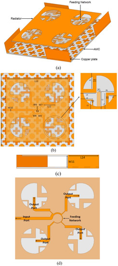
Figure 1.
Configuration of the presented antenna. (a) 3D view. (b) Top view and detail. (c) Side view. (d) Feeding network.
2.2. Design of CP Antenna Unit
Figure 2 gives the evolution process of the antenna design, which can be divided into four stages. Antenna 1 is a straightforward microstrip line-fed circular wide-slot antenna, and the simulation results are in Figure 3 show that antenna 1 has good impedance matching. However, the antenna has only line polarization radiation. As the L-shaped branch increases, antenna 2 and antenna 3 have CP radiation characteristics. The AR bandwidth also spreads with the increase of L-shaped branches. However, the impedance bandwidth decreases instead due to poor impedance matching. The structure proposed in this paper is shown as antenna 4, which has good impedance matching. The AR bandwidth and impedance bandwidth of the antenna are better than those of the first three antennas. The current distribution of antenna 4 is exhibited in Figure 4. The right-hand polarized radiation will appear along the +z direction, while the left-hand polarized radiation will travel in the −z direction.
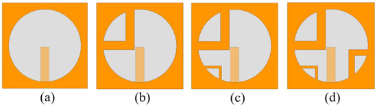
Figure 2.
Four reference prototypes in the design process of circular slot antenna. (a) Ant.1. (b) Ant.2. (c) Ant.3. (d) Ant.4.
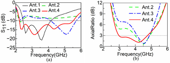
Figure 3.
S11 and AR curves for different antennas. (a) S11. (b) AR curves.
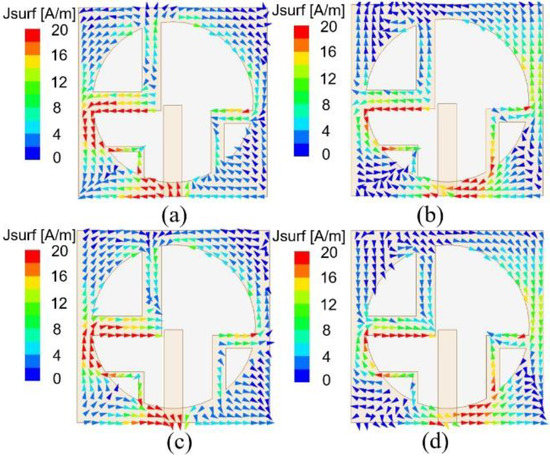
Figure 4.
Distribution of the surface current on the antenna at 4 GHz in the phases of (a) 0°, (b) 90°, (c) 180° and (d) 270°.
2.3. AMC Structure Design and Analysis
The antenna works in the indoor environment, so it is indispensable to increase the radiation of the antenna in the +z direction to reduce the backward radiation. The AMC structure is used as the reflector plate to increase the radiation in the +z direction by using its characteristic of in-phase reflection. Both the PEC plate and the AMC structure can reflect −z direction radiation and enhance +z direction radiation, while the in-phase reflection characteristics of the AMC structure can significantly reduce the antenna profile and miniaturize the antenna. Figure 5a,b describe the corresponding impedance bandwidth and AR bandwidth with and without the AMC structure loaded. We can understand intuitively that the introduction of the AMC structure has little influence on the bandwidth, as only a certain frequency shift occurs. The reflected phase bandwidth of the AMC unit can be seen in Figure 5c, and we define the frequency band in the interval [−90°, 90°] as the in-phase bandwidth, centered on the reflected phase at 0 degrees. The air layer height, H3, has a large effect on the in-phase reflection bandwidth of the AMC structure, and a red shift occurs with the gradual increase of H3. The in-phase reflection bandwidth of the AMC covers the working bandwidth of the antenna. The antenna gain is significantly improved, as depicted in Figure 5d. The antenna has a good broadband performance but deteriorates in the 3.18–3.76 GHz range. In view of the above situation, four metal plates are added around the AMC structure. In the actual processing, copper plates are used. Vertical metal plates have no obvious influence on impedance bandwidth and gain performance. The surface current distribution of the metal plate is shown in Figure 6. By observing the current distribution, it can be seen that part of the electromagnetic wave radiated by the SP-fed wide-slit antenna above is coupled to the edge of the vertical metal plate and the ground floor, which increases the current path and achieves the purpose of widening the antenna axis ratio bandwidth.
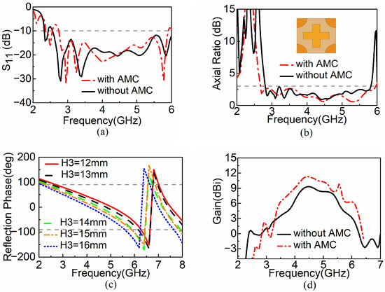
Figure 5.
Influence of AMC structure on antenna performance and parameter scanning of air layer height. (a) S11. (b) AR curves. (c) Air layer height H3. (d) Gain curves.
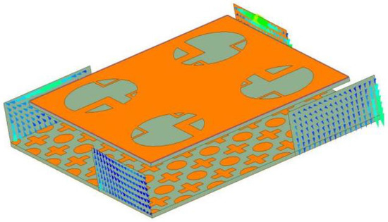
Figure 6.
Surface current distribution diagram of a metal plate.
3. Results’ Comparisons
To verify the rationality of the design, we fabricated and tested the SP-fed broadband CP circular slot array antenna loaded with an AMC. The field test environment is shown in Figure 7. The fabricated antenna sample is shown in Figure 8. As we can see, the air layer between the antenna and the AMC is supported by plastic posts; both are fixed with insulating tape and sideloaded with SMA connectors.
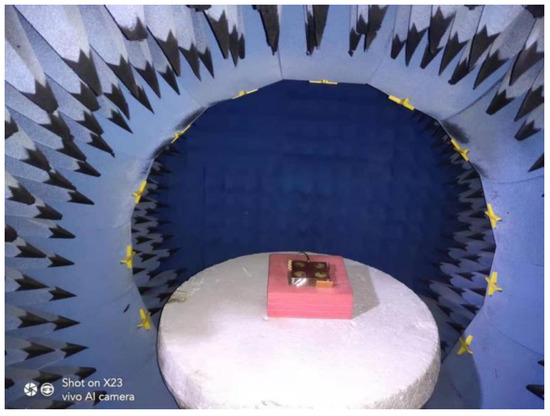
Figure 7.
Field test environment.
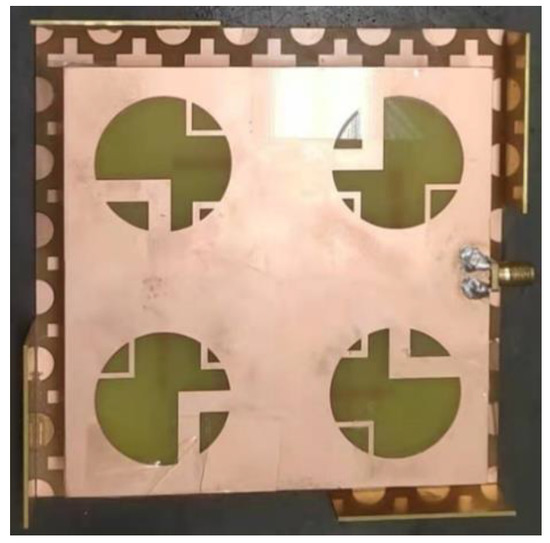
Figure 8.
The fabricated antenna sample.
Figure 9 presents the simulated and measured results of the design. Figure 9a depicts that the impedance bandwidth of the measurement is 77.7% (2.74–6.22 GHz), while the simulation is from 2.74 GHz to 5.91 GHz. The simulated and measured AR bandwidths (AR < 3 dB) is in Figure 9b are 2.82–5.82 GHz and 3.00–5.90 GHz, respectively. From the simulated results, the CP operating bandwidth has 94.63% coverage for the whole operating band in our design. Figure 9c displays the in-band gain, where the measured gain peak is 11.1 dBi at 4.4 GHz. From the comparison of the above measurement, there is a small difference compared with the simulated result; the first reason for the difference is the unstable positioning of the antenna air layer; the second reason is the processing error and the deviation of the FR4 substrate dielectric constant. Figure 10 displays the radiation direction of the antenna at three frequency points. The performance comparisons between the designed antenna and others are listed in Table 1. Part of the antennas proposed have simple structure and low profile, and obtain good broadband performance at the same time [9,18,21]. For backward radiation, most of the designs use the AMC structure or PEC as the reflecting surface [31,33,34,36]. In [37,38,39,40], CMA was used to design and optimize the working mode of the antenna, so that the bandwidth and directivity of the antenna were significantly improved, and the antenna sidelobe was extremely suppressed. The radiation direction pattern of the designed antenna was very symmetrical. In [39,40] both use multiple linear polarization (LP) modes to improve antenna CP bandwidth. Compared with [39], the performance of [40] is further improved. The antenna unit adopts the stack structure to obtain up to 5 LP modes. Finally, SRT is used to form the 2 × 2 array antenna, and the circular polarization bandwidth reaches 74%. The antenna bandwidth performance designed in this paper is better than in [37,38,39] and slightly less than in [40]. At the same time, compared with the above literature, the antenna design for sidelobe suppression and direction pattern optimization need to be improved. CMA needs to be used to further analyze the antenna working mode to optimize the antenna structure.
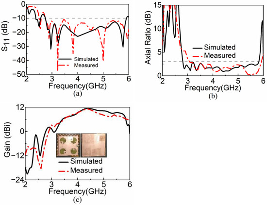
Figure 9.
Simulated and measured results of (a) S11. (b) AR curves. (c) Gain curves.
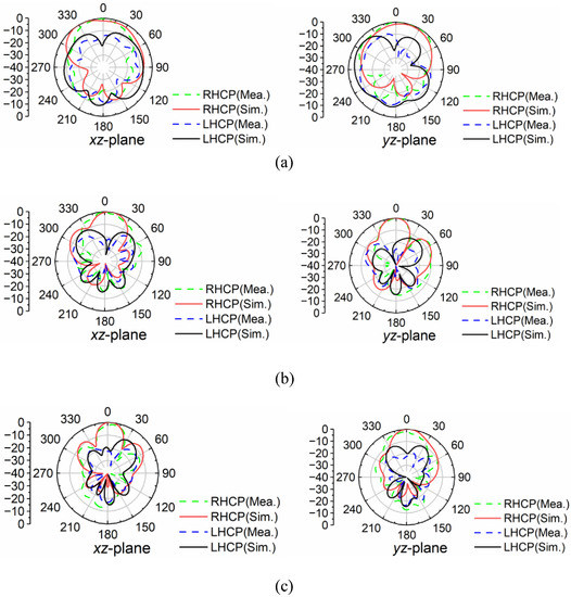
Figure 10.
The simulated and measured radiation patterns of the proposed antenna at (a) 3.0 GHz, (b) 4.0 GHz, and (c) 5.0 GHz.

Table 1.
Comparison of the proposed antenna to previous antennas.
4. Conclusions
In this work, an SP-fed broadband CP circular slot array antenna loaded with an AMC structure was presented. The design method of the antenna and the principle of action of the AMC structure were analyzed and tested in a SATMO microwave anechoic chamber. First, the AR bandwidth is well widened by the introduction of the radiation unit, and the SP feed network is used to connect to form the array. Second, the AMC structure is applied to increase the radiation of the antenna in the +z direction and simultaneously reduce the antenna profile. The measurements prove that our designed antenna realizes impedance bandwidth (2.74–6.22 GHz) of 77.67% and AR bandwidth (3.00–5.90 GHz) of 65.16% with a low profile of 0.11λ0 (about 0.11λ0 at the center frequency of 4.5 GHz). Our designed SP-fed broadband CP circular slot array antenna with loaded AMC structure can be used in space-constrained environments such as indoor and dense building areas.
Author Contributions
Conceptualization, H.H.; methodology, H.H.; software, H.H.; validation, S.W.; formal analysis, H.G.; investigation, H.G.; data curation, X.M.; writing—original draft preparation, X.M.; writing—review and editing, X.H.; supervision, X.H. All authors have read and agreed to the published version of the manuscript.
Funding
This research received no external funding.
Institutional Review Board Statement
Not applicable.
Informed Consent Statement
Not applicable.
Data Availability Statement
All data are contained within the article.
Conflicts of Interest
The authors declare no conflict of interest.
References
- Wang, Z.; Liang, T.; Dong, Y. Metamaterial-Based, Compact, Wide Beam-Width Circularly Polarized Antenna for 5G Indoor Application. Microw. Opt. Technol. Lett. 2021, 63, 2171–2178. [Google Scholar] [CrossRef]
- Lee, K.F.; Tong, K.F. Microstrip Patch Antennasbasic Characteristics and Some Recent Advances. Proc. IEEE 2012, 100, 2169–2180. [Google Scholar]
- Hall, P.S. Application of Sequential Feeding to Wide Bandwidth, Circularly Polarised Microstrip Patch Arrays. IEE Proc. H Microw. Antennas Propag. 1989, 136, 390–398. [Google Scholar] [CrossRef]
- Jiang, Y.; Geyi, W.; Yang, L.; Sun, H. Circularly-Polarized Focused Microstrip Antenna Arrays. IEEE Antennas Wirel. Propag. Lett. 2016, 15, 52–55. [Google Scholar] [CrossRef]
- Lines, T.; Lin, S.; Lin, Y. A Compact Sequential-Phase Feed Using Uniform Transmission Lines for Circularly Polarized Sequential-Rotation Arrays. IEEE Trans. Antennas Propag. 2011, 59, 2721–2724. [Google Scholar]
- Li, Y.; Zhang, Z.; Feng, Z. A Sequential-Phase Feed Using a Circularly Polarized Shorted Loop Structure. IEEE Trans. Antennas Propag. 2013, 61, 1443–1447. [Google Scholar] [CrossRef]
- Yang, W.; Zhou, J.; Yu, Z.; Li, L. Bandwidth- and Gain-Enhanced Circularly Polarized Antenna Array Using Sequential Phase Feed. IEEE Antennas Wirel. Propag. Lett. 2014, 13, 1215–1218. [Google Scholar] [CrossRef]
- Deng, C.; Li, Y.; Zhang, Z.; Feng, Z. A Wideband Sequential-Phase Fed Circularly Polarized Patch Array. IEEE Trans. Antennas Propag. 2014, 62, 3890–3893. [Google Scholar] [CrossRef]
- Wang, L.; Zhu, Z.; En, Y. Performance Enhancement of Broadband Circularly Polarized Slot-Microstrip Antenna Using Parasitic Elements. IEEE Antennas Wirel. Propag. Lett. 2021, 20, 2255–2259. [Google Scholar] [CrossRef]
- Ding, K.; Gao, C.; Yu, T.; Qu, D.; Zhang, B. Gain-Improved Broadband Circularly Polarized Antenna Array with Parasitic Patches. IEEE Antennas Wirel. Propag. Lett. 2017, 16, 1468–1471. [Google Scholar] [CrossRef]
- Mohammadi-Asl, S.; Nourinia, J.; Ghobadi, C.; Majidzadeh, M. Targeting Wideband Circular Polarization: An Efficient 2 × 2 Sequentially-Phase-Fed Rotated Array Antenna. Radioengineering 2018, 27, 79–84. [Google Scholar] [CrossRef]
- Rafii, V.; Nourinia, J.; Ghobadi, C.; Pourahmadazar, J.; Virdee, B.S. Broadband Circularly Polarized Slot Antenna Array Using Sequentially Rotated Techniquefor C-Band Applications. IEEE Antennas Wirel. Propag. Lett. 2013, 12, 128–131. [Google Scholar] [CrossRef]
- Deng, C.; Li, Y.; Zhang, Z.; Feng, Z. A Wideband Isotropic Radiated Planar Antenna Using Sequential Rotated L-Shaped Monopoles. IEEE Trans. Antennas Propag. 2014, 62, 1461–1464. [Google Scholar] [CrossRef]
- Karamzadeh, S.; Rafii, V.; Kartal, M.; Ucan, O.N.; Virdee, B.S. Circularly Polarised Array Antenna with Cascade Feed Network for Broadband Application in C-Band. Electron. Lett. 2014, 50, 1184–1186. [Google Scholar] [CrossRef]
- Ta, S.X.; Park, I. Compact Wideband Sequential-Phase Feed for Sequentially Rotated Antenna Arrays. IEEE Antennas Wirel. Propag. Lett. 2017, 16, 661–664. [Google Scholar] [CrossRef]
- Eskandari, H.; Booket, M.R.; Kamyab, M.; Veysi, M. Investigations on a Class of Wideband Printed Slot Antenna. IEEE Antennas Wirel. Propag. Lett. 2011, 9, 1221–1224. [Google Scholar] [CrossRef]
- Karamzadeh, S.; Rafii, V.; Saygin, H.; Kartal, M. Polarisation Diversity Cavity Back ReconFigureurable Array Antenna for C-Band Application. IET Microw. Antennas Propag. 2016, 10, 955–960. [Google Scholar] [CrossRef]
- Siahcheshm, A.; Nourinia, J.; Ghobadi, C.; Karamirad, M.; Mohammadi, B. A Broadband Circularly Polarized Cavity-Backed Archimedean Spiral Array Antenna for C-Band Applications. AEU—Int. J. Electron. Commun. 2017, 81, 218–226. [Google Scholar] [CrossRef]
- Bisharat, D.J.; Liao, S.; Xue, Q. Wideband Unidirectional Circularly Polarized Antenna with L-Shaped Radiator Structure. IEEE Antennas Wirel. Propag. Lett. 2017, 16, 12–15. [Google Scholar] [CrossRef]
- Chung, K.L.; Li, Y.; Zhang, C. Broadband Artistic Antenna Array Composed of Circularly-Polarized Wang-Shaped Patch Elements. AEU—Int. J. Electron. Commun. 2017, 74, 116–122. [Google Scholar] [CrossRef]
- Maddio, S. A Compact Wideband Circularly Polarized Antenna Array for C-Band Applications. IEEE Antennas Wirel. Propag. Lett. 2015, 14, 1081–1084. [Google Scholar] [CrossRef]
- Dong, Y.; Itoh, T. Metamaterial-Based Antennas. Proc. IEEE 2012, 100, 2271–2285. [Google Scholar] [CrossRef]
- Technologies, W.; Ale, J.; Highway, A.; Atlasbaf, Z. New Ku-Band Reflectarray Antenna by Using Anisotropic Superstrate on an Artificial Magnetic Conductor. Int. J. Microw. Wirel. Technol. 2016, 9, 831–841. [Google Scholar]
- Ta, S.X.; Park, I. Compact Wideband Circularly Polarized Patch Antenna Array Using Metasurface. IEEE Antennas Wirel. Propag. Lett. 2017, 16, 1932–1936. [Google Scholar] [CrossRef]
- Chen, Q.; Zhang, G.; He, C.; Fan, Y.; Zhu, Z.; Zhang, D.; Li, J.; Zhao, Y. Wideband and High-Gain Circularly-Polarized L-Shaped Slot Antenna Array Using Metamaterial. Int. J. Microw. Wirel. Technol. 2021, 13, 359–364. [Google Scholar] [CrossRef]
- Yang, W.; Meng, Q.; Che, W.; Gu, L.; Xue, Q. Low-Profile Wideband Dual-Circularly Polarized Metasurface Antenna Array with Large Beamwidth. IEEE Antennas Wirel. Propag. Lett. 2018, 17, 1613–1616. [Google Scholar] [CrossRef]
- Ta, S.X.; Park, I. Planar Wideband Circularly Polarized Metasurface-Based Antenna Array. J. Electromagn. Waves Appl. 2016, 30, 1620–1630. [Google Scholar] [CrossRef]
- Zhao, Z.H.; Zhang, H.F. A Wide-Band Circularly Polarized Antenna Array Using a Sequential Phase Feed Structure Applied to 5G-Band. J. Electromagn. Waves Appl. 2021, 35, 2141–2152. [Google Scholar] [CrossRef]
- Polarized, L.C.; With, A.; Enhancement, G.; Zheng, Q.; Guo, C.; Vandenbosch, G.A.E.; Ding, J. Reduction Using Polarization Conversion EBG Structures. IEEE Trans. Antennas Propag. 2020, 68, 2440–2445. [Google Scholar]
- Li, K.; Liu, Y.; Jia, Y.; Guo, Y.J. A Circularly Polarized High-Gain Antenna with Low RCS over a Wideband Using Chessboard Polarization Conversion Metasurfaces. IEEE Trans. Antennas Propag. 2017, 65, 4288–4292. [Google Scholar] [CrossRef]
- Feng, D.; Zhai, H.; Xi, L.; Yang, S.; Zhang, K.; Yang, D. A Broadband Low-Profile Circular-Polarized Antenna on an AMC Reflector. IEEE Antennas Wirel. Propag. Lett. 2017, 16, 2840–2843. [Google Scholar] [CrossRef]
- Cao, Y.F.; Zhang, X.Y.; Mo, T. Low-Profile Conical-Pattern Slot Antenna with Wideband Performance Using Artificial Magnetic Conductors. IEEE Trans. Antennas Propag. 2018, 66, 2210–2218. [Google Scholar] [CrossRef]
- Jiang, X.; Zhang, Z.; Li, Y.; Feng, Z. A Low-Cost Wideband Circularly Polarized Slot Array with Integrated Feeding Network and Reduced Height. IEEE Antennas Wirel. Propag. Lett. 2016, 15, 222–225. [Google Scholar] [CrossRef]
- Xu, R.; Li, J.; Kun, W. A Broadband Circularly Polarized Crossed-Dipole Antenna. IEEE Trans. Antennas Propag. 2016, 64, 4509–4513. [Google Scholar] [CrossRef]
- Pan, C.Y.; Chen, H.Y. Circularly Polarized Sequentially Rotated Antenna Array for Dual-Band WLAN Applications. Int. J. RF Microw. Comput. Eng. 2021, 31, e22590. [Google Scholar] [CrossRef]
- Siahcheshm, A.; Nourinia, J.; Ghobadi, C. Circularly Polarized Antenna Array with a New Sequential Phase Feed Network Utilizing Directional Coupler. AEU—Int. J. Electron. Commun. 2018, 93, 75–82. [Google Scholar] [CrossRef]
- Gao, X.; Tian, G.; Shou, Z.; Li, S. A Low-Profile Broadband Circularly Polarized Patch. IEEE Antennas Wirel. Propag. Lett. 2021, 20, 214–218. [Google Scholar] [CrossRef]
- Lin, J.; Zhu, L. Low-Profile High-Directivity Circularly-Polarized Differential-Fed Patch Antenna with Characteristic Modes Analysis. IEEE Trans. Antennas Propag. 2020, 69, 723–733. [Google Scholar] [CrossRef]
- Zeng, J.; Member, G.S.; Liang, X.; Member, S.; He, L. Single-Fed Triple-Mode Wideband Circularly. IEEE Trans. Antennas Propag. 2022, 70, 846–855. [Google Scholar] [CrossRef]
- Zeng, J.; Member, G.S.; Zhang, Z. Penta-Mode Ultrawideband Circularly. IEEE Trans. Antennas Propag. 2022, 70, 9051–9060. [Google Scholar] [CrossRef]


Disclaimer/Publisher’s Note: The statements, opinions and data contained in all publications are solely those of the individual author(s) and contributor(s) and not of MDPI and/or the editor(s). MDPI and/or the editor(s) disclaim responsibility for any injury to people or property resulting from any ideas, methods, instructions or products referred to in the content. |
© 2023 by the authors. Licensee MDPI, Basel, Switzerland. This article is an open access article distributed under the terms and conditions of the Creative Commons Attribution (CC BY) license (https://creativecommons.org/licenses/by/4.0/).