Abstract
The main cable shape control confronts new challenges when a suspension bridge’s span exceeds two kilometers. As a suspension bridge’s primary load-bearing component, it is difficult to alter the alignment once the erection is completed. Hence, the accurate calculation and control of the main cable shape has significant scientific research value from various aspects. This paper systematically reviews the research progress of the suspension bridge’s main cable shape control technology. The current research progress is introduced from three aspects of main cable shape-finding, construction control technology, and control analysis, and both the current shortcomings and future research directions are summarized. This review paper is expected to be a solid reference for investigators and experts in this crucial field of structural engineering.
1. Introduction
Suspension bridges play a vital role in modern bridge structures, with their good structural performance, huge spanning capacity, and beautiful shape. The progress of modern calculation theory [1], high-strength materials [2], computer technology [3], and construction methods [4,5] has made the suspension bridge develop rapidly, and the maximum span record has been repeatedly updated. In 2022, the completion of the Canakkale 1915 Bridge [6] in Turkey marked that the suspension bridge’s span has entered the era of two kilometers. The Zhang Jinggao Yangtze River Bridge, now under construction in China, will continue to refresh the suspension bridge’s record for the longest span, with a main span of 2300 m. The bridge construction is gradually expanding to important sea-crossing channels and deep mountain canyons, where the construction conditions are more complex, and the span and scale of the bridge are larger. Undoubtedly, new challenges are put forward to the structural design method, construction method, and control technology, mainly manifested in (1) a large span and a more prominent structural nonlinearity [7,8], (2) a longer construction period and more complex construction method [9,10], and (3) greater sensitivity to environmental factors and construction errors [11]. The main cable’s shape has a direct bearing on a long-span suspension bridge’s safety and appearance. To guarantee that the finished bridge’s geometric alignment complies with design specifications and that the structure’s internal forces reach the optimal state, strict construction control must be applied in the construction process [12]. The suspension bridge’s cable shape control has always been the focus of attention due to the difficulty of constructional control. As a suspension bridge’s primary load-bearing component, it is difficult to alter the alignment once it has been erected. The erection error of the free cable shape will have a substantial impact on subsequent construction stages. Therefore, when erecting the main cable, it is essential to guarantee the shape’s precision to the greatest extent possible [13], and there should be a control and evaluation standard for its error. To match the ideal state to the maximum extent, the free cable shape needs to rely on reliable calculation parameters and accurate calculation methods, coupled with strict manufacturing and construction quality control. This paper reviews the current status of research on the control of the suspension bridge’s main cable shape from three aspects: main cable shape-finding, construction control technology, and control analysis. The current research’s shortcomings are summarized, and the future development directions of this field are discussed.
2. The Development of the Shape-Finding Calculation Theory for Main Cables
The process of determining the main cable’s initial shape in accordance with the requirements of the internal and external force balance is commonly known as shape-finding [14,15,16], which is the prerequisite for controlling the main cable shape. Since the main cable has prominent nonlinear characteristics, determining its shape becomes a key and difficult aspect of its structural analysis. The calculating theory for the suspension bridge’s main cable shape has undergone a protracted development phase. Many investigators have devoted their studies to this hot topic and have accumulated many calculation methods. Generally speaking, the calculation methods of the suspension bridge’s cable shape can be divided into the analytical approach and the finite element method [17]. The current related research mainly focuses on the optimization of calculation methods and refined analysis.
2.1. Analytical Methods
If the weight of the cable is uniformly distributed across its span, the cable will align parabolically and will have a constant horizontal component force [18] (i.e., the parabolic theory of shape-finding of the main cable). The aforementioned theory ignores the cable’s weight distribution along the cable curve, which is only applicable to bridges with a small span. To overcome the limitations of the parabolic theory, several studies were carried out by numerous academics, and then the segmental linear method [19], the segmental parabolic method [20], and the segmental catenary method (SCM) [21] were proposed. Additionally, the above methods have been summarized in Ref. [21], and the comparison accuracy and application scope of the above calculation methods for the bridge completion state of the main cable were presented through examples.
- (1)
- The optimization of calculation methods
The spatial cable suspension bridge and three-tower suspension bridge make the traditional calculation method face new challenges. Therefore, some scholars have proposed a new calculation method based on the traditional SCM to analyze the shape-finding problem of space cables and multi-span main cables. Consider the problem where the coupling effect between the space cable and the boom makes the main cable form-finding complex and difficult to converge. Zheng et al. [22] employed the least-squares method with Marquardt correction to solve the linear calculation of spatial cable plane suspension bridges. This method was easy to converge and had high precision, but it was only applicable to the case where the hanger is only inclined in the transverse direction of the bridge. To solve the above problem, Wu et al. [23] also derived the bridge alignment analytical formula of the spatial special-shaped main cable, considering the coupling effect of the spatial main cable and hanger, which can consider the case where the hanger is inclined in both the longitudinal and transverse directions. In addition, considering the particularity of the main cable form finding of the three-tower suspension bridge, a three-tower space cable shape-finding algorithm with an unequal main span on the basis of the SCM was developed by Zhang et al. [17]. As shown in the calculation flowchart of Figure 1, the main span, secondary main span, side span, and anchor span were solved and analyzed in turn. The control equations equal to the number of basic unknowns were established using the equilibrium conditions of geometric compatibility and force, and the appropriate values of basic unknowns were evaluated.
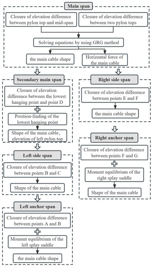
Figure 1.
The main cable’s shape-finding flowchart.
It can be concluded from the above literature that the current analysis objects of main cable shape-finding were mainly concentrated on unconventional spatial cables and multi-tower suspension bridges, but the analysis method was still based on the traditional SCM. Additionally, based on the SCM method, an analytical calculation method that captured the coupling effect of the main cable-hanger-stiffening beam system was established by Wang et al., [7] which can calculate the mechanical properties of the whole structure and the correlation of each component. Due to the poor convergence performance and the low computational efficiency of the SCM, some scholars have proposed a new method for the main cable shape-finding. The suspension bridge’s main cable shape was analyzed by Deng et al. [24] by implementing a slope climbing method. The position and slope of the main cable’s lowest point were then determined using the unified linear equations for each cable section. The deformation compatibility condition was employed to construct the corresponding equations, and the variation law of the main cable force’s horizontal component force was then employed to solve them. Liu et al. [25] developed a novel coordinate system approach based on the overall mechanical analysis to assess the self-anchored suspension bridge’s cable shape, which had a good convergence speed and calculation accuracy. This methodology took the main cable as a whole for stress analysis. It was assumed that the original cable shape would be a straight line; the reaction forces were calculated, and then the iteration process calculations were carried out. After that, a modified force density method [26] was suggested for determining the main cable’s shape, and the structural balancing equation was exploited to evaluate the coordinates of the main cable nodes. The method had stable convergence and a high computational efficiency.
At present, the shape-finding calculation has high calculation accuracy, which can meet the engineering requirements, and the calculation efficiency attracted more and more attention. Therefore, some scholars have greatly improved on the computational efficiency by introducing intelligent optimization algorithms with the help of the powerful computing power of computers. An improved particle swarm optimization (IPSO) algorithm proposed by Chen et al. [27] can be exploited for the calculation of the main cable shape subjected to various initial values, complex boundaries, and load conditions. The developed methodology was able to solve the difficulty of the initial value setting and the calculation convergence of the traditional Newton-Raphson method. The computational efficiencies of four different methods, namely, genetic algorithm (GA), particle swarm optimization (PSO), GA-PSO, and IPSO, were also compared. Figure 2 presents that IPSO has a higher computational accuracy and efficiency than other ones. Cao et al. [28,29] also established two efficient shape-finding methods, namely, the explicit analytical iteration method and the enhanced particle swarm optimization (EPSO). The harmony search (HS), GA, PSO, and the proposed EPSO are the four approaches that are being compared in Figure 3 for their computational effectiveness. Commonly, the EPSO is the most effective strategy, saving more than 60% in computing time when compared to the other three approaches.
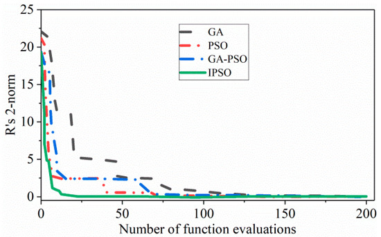
Figure 2.
Comparison of the four methods’ convergence rates.
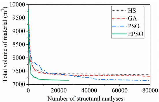
Figure 3.
Comparison of different optimization approaches.
- (2)
- The refined analysis
However, most of the above studies did not consider the influence of the geometric relationship between the saddle and the main cable on the main cable shape. An accurate analysis of the tangent relationship between the saddle and the main cable is necessary for shape-finding. Therefore, a novel approach for computing the suspension bridge’s saddle pre-deviation was proposed by Wang et al. [30]. This method modified the stress-free cable length by taking into account the influence of various tangent points, non-contact segments, and cable-saddle friction. Finally, the method’s reliability was verified via the model test. By considering the saddle’s impact on the length of the main cable, the main cable curve correction algorithm at the saddle was derived by Gao et al. [31] from the perspective of the geometric relationship. To this end, the obtained binary nonlinear equations were analyzed via the Newton-Raphson method. Luo et al. [32] developed a high-precision calculation method for the finished bridge alignment of the pinned cable clip suspension bridge. The main cable and hanger’s stress-free length were precisely analyzed using this approach, which considered the tangent contact condition and the friction impact between the main cable and the saddle, as well as the influence of the clamp on the main cable and hanger. By utilizing the dichotomy method, Deng et al. [33] proposed an enhanced algorithm that had great convergence for locating the saddle position of a composite curve. Additionally, a methodology [34] was established for addressing the suspension bridge’s target configuration while taking the saddle effect into account. The method introduced the geometric equations of the main cable and the saddle into the SCM to solve the shape of the main cable, and the flow chart of the calculation method is shown in Figure 4.
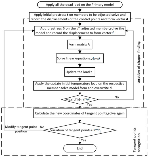
Figure 4.
Flow chart for shape-finding, considering saddles.
In summary, the special mechanical properties made the spatial cable suspension bridge and the multi-tower suspension bridge become the hot research objects of the main cable shape-finding. The SCM and its derivative methods are the mainstream methods for shape-finding. In order to derive the recursive relationship between linear parameters, specific prerequisites, such as mechanical balance and geometric compatibility, are essential. At the same time, there are also some new methods different from the SCM, which enrich the means of main cable shape-finding. The introduction of an intelligent optimization algorithm in the shape-finding process can greatly improve computational efficiency. By introducing the geometric relationship and the physical relationship between the saddle and the main cable into the piecewise catenary equation, the main cable shape-finding calculation system was more accurate and perfect.
2.2. Finite Element Method (FEM)
With the continuous development of computer applications in engineering calculations, a nonlinear FEM based on the strict mathematical formula derivation and finite displacement theory was produced. The cable element and tangent stiffness matrix are the basis of the FEM. At present, there are three main approaches to simulate cable elements: rod element [35], multi-node curved cable element [36], and two-node catenary element [37,38]. The rod element method divides the cable into many hinged rod elements to simulate the curvy shape of the cable. This approach not only has a low calculation accuracy, but it also cannot capture the actual cable shape well. Due to a large number of nodes, the program processing of the multi-node curved element method is multifaceted, and obtaining the explicit stiffness matrix is challenging. The catenary element approach, which has few nodes and can simulate any stress level and length of the suspension cable with high accuracy, can be utilized to assess the explicit stiffness matrix. As a result, this element has emerged as the top option for the shape-finding calculations of the main cable of suspension bridges [39]. Since the catenary element was first used to simulate the suspension cable catenary, many investigators have improved and refined the catenary approach, and have exploited that in the analysis of the suspension bridge’s cable.
- (1)
- The optimization of calculation methods
The tangential stiffness matrix of the catenary cable element was derived from the exact analytical formula to obtain the cable shape and node force. The geometric state and internal force state of the whole cable could be determined using the known stress-free length and node coordinates, thus simplifying the shape-finding analysis of the cable structure.
The target configurations under dead loads (TCUD) methodology originally defined by Kim et al. [40] is a classical method for shape-finding of the main cable of a suspension bridge, which uses the target configuration of the structure under dead loads to solve the linear equilibrium equation of the cable element, with the node coordinates and the length of the strain-free element as unknown quantities. Some scholars have solved the problem where the determination of the main cable shape of the self-anchored suspension bridge is affected by the axial deformation of the bridge tower and the beam by improving the TCUD method [16,41], and later it has been extended to solve the main cable shape of the 3D suspension bridge [42].
Sun et al. [43] established the equilibrium equation of each segment force of the main cable and comprehended the 3D cable’s shape-finding by employing the coordinate and matrix iteration approach. Furthermore, formulations of geometrically nonlinear total Lagrangian-based FEM [44] that can be applied to 3D and 2D cables were displayed. A representative application revealed that this approach was successful in both static and transient analyses.
Some scholars have also conducted a series of investigations to enhance computational efficiency. A nonlinear FEM and interaction matrix-based analysis methodology was developed by Wang et al. [45], which was able to reasonably predict suspension bridge shapes conveniently and efficiently. For the main cable system’s nonlinear analysis under the static action, Li et al. [46] established a catenary element. Based on the accurate analytical expression of the elastic catenary, the element’s internal forces in each direction, as well as the tangent stiffness matrix, were explicitly determined. The penalty factor search algorithm was also introduced to improve on the calculation accuracy and the convergence rate. Based on the elastic catenary theory, a novel method for determining the main cable’s shape of a suspension bridge was developed by Zhou et al. [47]. Through the application of this approach, the whole bridge structure was nonlinearly analyzed, avoiding the complexities and mistakes of the traditional method’s assumptions on boundary conditions, virtual restrictions, and the creation of equilibrium equations for a single cable system. Zhu et al. [48] established a shape-finding approach for a suspension bridge main cable based on a nonlinear FEM in the context of the Eulerian description. Firstly, the control differential equation of the main cable in 3D space was constructed by analyzing the cable as a whole, and then following the introduction of the 1D linear form function, the Newton iteration approach was implemented to evaluate the main cable shape.
It can be seen that the optimization of the FEM based on the catenary element mostly focuses on the shape-finding of the space cable. Even though complex nonlinear equations are transformed into linearized equations in shape-finding calculations, iterative calculations are still required in the process of solving the element stiffness matrix, due to the coupling of equations between the elements. Some new computational methods were proposed to improve the efficiency of iterative computation, such as the penalty factor search algorithm and whole mechanical analysis method.
- (2)
- The refined analysis
It is worth mentioning that in all cases, the main cable should be tangential to the saddle, and the tangent point is continually varying. The saddle directly restricts the deformation of the main cable. The above research did not consider this problem. A flexible iterative approach taking into account the slip effect between the main cable and the saddle was developed by Chen et al. [49]. Firstly, the nonlinear equation was linearized by the first-order Taylor expansion, and the numerical approach was exploited to derive the catenary element’s tangent stiffness matrix. The Newton-Raphson method was implemented to evaluate the finished main cable shape, free cable shape, and saddle pre-deviation under dead load. It is crucial to realistically simulate the saddle in the process of solving the main cable shape via FEM. The simplified approach exploited by the majority of researchers involved simulating the tangent point and eccentricity of the saddle with multiple rod units and rigid arms. Fan et al. [50] constructed a multi-node saddle element composed of five-rod elements to consider the movement of the saddle and the change of the tangent position. As demonstrated in Figure 5a, the saddle is composed of rod elements ①~⑤; ⑥ and ⑦ are the tower top, and the main cable’s tangent points on the saddle are nodes 1 and 2. The saddle pushing process is simulated by translating the coordinates of nodes 1~6. Xu [51] employed four beam elements to simulate the saddle and pushing process. According to Figure 5b, the vertical and horizontal forces produced by the main cable’s tension are transmitted to the tower top by employing the straight bar elements with large axial stiffness between points 1 and 6 and between points 6 and 7, respectively. The main cable’s tangent points on the saddle are 2 and 3. The simulation approach is the same as that provided in Ref. [50], and the calculation’s precision is not particularly good. The main cable’s stress-free length in the suspension section cannot be modified according to changes in the tangent point’s position in relation to the saddle.
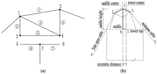
Figure 5.
The saddle’s finite element simulation. (a) The saddle consists of five-rod elements. (b) Four beam elements simulate the saddle and pushing process.
To solve the above problem, a more accurate simulation methodology [52] for the saddle was developed, as demonstrated in Figure 6. To simulate the saddle body, the rigid beam elements were radially arranged along the saddle’s upper surface. A changing range for the tangent point between the main saddle and the main cable was established in the encryption area. The saddle top in the encryption area was linked to the main cable using compression-only connections, which can simulate the separating state and how their tangent point positions vary at each stage. Since the middle position of the saddle was not separated from the cable at any time, a rigid connection was adopted. However, this simulation method is too complicated.
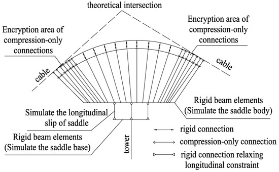
Figure 6.
Finite element simulation of the saddle.
Because the method of simulating the saddle by combining multiple rod elements suffers from low calculation accuracy, some investigators proposed new element forms to simulate the saddle. Luo et al. [53] first developed a saddle-cable element that can automatically satisfy the two crucial conditions, namely, that the main cable is tangent to the saddle and that the main cable’s stress-free length remains unchanged. The element can easily simulate various saddles and pushing processes, and it had a high computational efficiency and accuracy. However, it is only applicable to plane cable analysis. Qi [54] proposed the saddle element, which can be implemented for the finite element calculations of the plane or space cable suspension bridges.
From the above literature analysis, although the principle of simulating a cable saddle structure via a rod element is simple, the modeling process is complex and the accuracy is insufficient. The cable saddle element can efficiently analyze the influence of the cable saddle on the main cable, and the calculation accuracy is better than that of the rod element.
2.3. The Combined Method
The analytical method is simple and has a high computational efficiency and accuracy, but it is only used to analyze the cable structure; while FEM can analyze the whole suspension bridge, the computational amount is large and the accuracy is low. Considering the respective characteristics of the analytical method and FEM, some academics have suggested merging the two approaches to create an effective methodology for evaluating the main cable’s shape [55,56]. The calculation principles of Refs. [55,56] are the same. Firstly, the initial value of the hanger tension was given, and then the cable alignment was solved through the analytical method. Then, the obtained cable alignment was input into the finite element model of the whole bridge, together with the hanger tensions for nonlinear analysis. The optimal hanger tensions were used as the convergence criterion to determine the reasonable bridge state. The calculation process is shown in Figure 7.
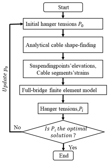
Figure 7.
Flow chart of the calculation process.
3. Construction Control Technology of the Main Cable
3.1. Construction Methods
The main cable construction approaches of a suspension bridge are the air spinning (AS) and prefabricated parallel wire strand (PPWS) methods. The AS method takes the steel wire as the traction unit, multiple wires are made into a strand in the catwalk, and then multiple strands are bound to form the main cable. Different from the AS method, the PPWS method takes the cable strand as the traction unit, and then strands are bound to the main cable. The AS approach has been broadly utilized in the United States and Europe, and the PPWS method has been extensively employed in Japan [57,58]. China has mastered the PPWS erection technology [4] by referring to Japan.
- (1)
- AS method
The study of the AS approach has had a long history in Europe and America, but there are few practical engineering cases built in recent years, which leads to little relevant information being available. Most suspension bridges in China are built on the basis of the PPWS approach for the main cable erection, and there are few investigations on the AS method. The Yang Baoshan Bridge completed in 2022 is the first bridge constructed by China independently using the AS method, which is of great significance. The main cable’s construction principle and the technology of the AS method for the Yang Baoshan Bridge were reported by Liu et al. [59]. It was pointed out that as the main cable was erected, the wire was released by the unreeling machine, and the constant tension of the wire was adjusted by the tension tower. The steel wire was driven back and forth between the two banks by a spinning wheel, thus carrying out wire erection operations. When the spinning wheel reaches the strand shoe position on both sides, the workers pull the steel wire out of the spinning wheel and hang it on the strand shoe, repeating the above operation until the single strand was erected. The basic principle of erection has been demonstrated in Figure 8. Since the 21st century, suspension bridges have been also rapidly developed in Republic of Korea. Moon et al. [60] introduced some improvement measures in the process of erecting the main cable using the AS method at the Yi Sun-Shin Bridge in Republic of Korea, focusing on the improvement of the spinning wheel to effectively avoid wire derailment during the erection process. To efficiently erect the main cable for long-span suspension bridges, the AS and PPWS technologies and associated equipment were currently being developed in Republic of Korea, based on a report by Kim et al. [5]. Kim et al. [61] briefly reported the erection methods and technical characteristics of five types of suspension bridges in Republic of Korea.
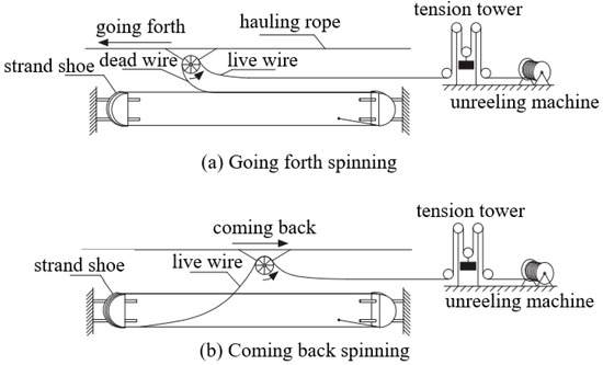
Figure 8.
Construction principle of the AS method.
- (2)
- PPWS method
PPWS is an approach of transporting prefabricated parallel high-strength steel wire strands to the site for installation. The main procedures of the PPWS method have been presented in Figure 9. Yoo et al. [62] reported the latest development and application of high-strength prefabricated parallel steel wire in Republic of Korea. The development and application process of high-strength PPWS strand were mainly introduced, including the test results of the strand performance test. The production system of the PPWS was also introduced, and the key points of its production equipment and production process were expounded. Recently, a 1960 MPa grade steel wire cable strand [2] was created in China, and it was successfully used on the Nansha Bridge. The excellent mechanical properties of the strand were investigated through tests and numerical analysis.
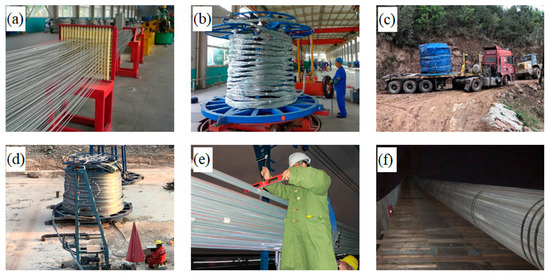
Figure 9.
The main procedures of the PPWS method: (a) arrangement and binding of the steel wire, (b) the strand forming, (c) transportation of the strand, (d) the traction of the strand, (e) adjustment of the strand, (f) main cable forming.
The AS and PPWS approaches have different characteristics. The suitable main cable erection method should be selected based on the needs of the features of the construction conditions, the main cable quality, construction period, and cost requirements. The characteristics of these two main methods based on the analysis given in the literature have been summarized in Table 1.

Table 1.
Summary of characteristics of two methods.
3.2. Sag Control of Cable Strands
An important step in building the main cable is adjusting the strands’ sag. Controlling the sag of the cable strand, regardless of the type of erection technique used, is essential for maintaining control over the main cable shape. Particularly, China is experiencing a period of tremendous development for suspension bridges, where many of the recent works on this subject have been carried out. Through literature surveys [57,64,65,66], the general principles for the current adjustment of the sag of cable strands are summarized in the following.
- (1)
- Sag adjustment method
In installing the main cable, the first strand is usually exploited as the reference strand, whose mid-span sag is controlled through absolute elevation. A strand other than the reference strand is called a general strand, whose mid-span sag is controlled by the height difference from the reference strand. The adjustment of each cable strand is carried out in accordance with the principle of the main span first, then the side span, and finally, the anchor span.
The core of sag adjustment calculation is aimed at determining the relationship equation between the adjustment of the unstressed cable length and the deviation of the sag, which is called the cable adjustment formula here. Although the cable adjustment formula [67,68] derived from the parabolic theory is easy to calculate, there are differences between the parabola and the actual shape of the cable. Tan et al. [69] used catenary theory to derive the cable adjustment formula and obtained accurate results. However, the calculation is cumbersome and requires repeated iterations. Unlike the above derivation, Wang [70] utilized the strand adjustment formula obtained via data fitting to adjust the reference strand of the Ying Wuzhou Yangtze River Bridge in China. An improved approach for reference strand adjustment calculation was also proposed by Deng et al. [71]. The main cable shape equation was expanded using the Taylor formula at the targetfree cable state. The relationship between the cable length adjustment and the mid-span vector height variation was then obtained by solving the expanded equation. The method is easy to calculate and is highly accurate.
The key to sag adjustment is to ensure the accuracy of the reference strand alignment. In order to prevent the reference strand from being squeezed and become drooping by the general strand in the later stage, some scholars have made special treatment of the reference strand, such as the use of relative reference strands [72,73], adding strands that are not part of the main cable as a reference [74], and canceling the sag adjustment step [75]. To reduce the error accumulation in the main cable erection of the Run Yang Bridge, Li et al. [72] reported that when adjusting the general strands, the three rows of strands at the bottom took the No. 1 strand as the reference, and when adjusting the sag of the remaining strands, a strand that had been adjusted at the same row or at the outermost of the next row was chosen as the reference. Then, the same approach was also exploited on Xi Houmen Bridge [73]. This was conducted to solve the problem where the reference strand was pressed by general strands in the later stage and could not be employed as a reference for general strand erection. A ruler strand [74] in Figure 10, separated from the main strand, was proposed as a reference for the alignment control of the main strand. Tang et al. [75] invented a strands erection methodology based on multi-standard wires, which can locate strands according to their marking points. Since the production accuracy of cable strands was enhanced by setting multiple standard wires, it was only necessary to align the cable strand mark points with the corresponding marks on the saddle during erection, and the strand sag did not need to be adjusted.
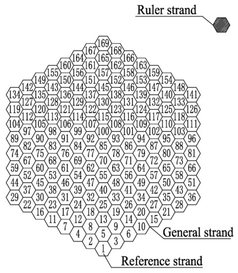
Figure 10.
Space position of strands.
- (2)
- Environmental conditions for the sag adjustment
The precision of the main cable erection is greatly influenced by temperature [76]. According to the construction specifications [66] in China, the sag adjustment of cable strand alignment should be carried out when the temperature becomes stable at night, and when the wind force is less than level 5. The temperature stability condition is that the temperature differences in the length direction and cross-section should not be greater than 2 °C and 1 °C, respectively.
In the sag measurement process of the cable strand, environmental factors such as temperature, wind, and rain lessen the measurement accuracy and efficiency, which directly affect the erection quality of the cable strand. Although a variety of advanced measurement techniques have been developed to enhance the measurement efficacy and accuracy, most of them were first proposed for the structural health monitoring of the finished bridges [77,78]. Although advanced measurement techniques in the construction process are not common, Huang et al. [74] proposed a general strands alignment measurement approach based on the vision, and developed a vision-based sag measurement system, as demonstrated in Figure 11. The actual height difference between the general strand and the reference strand was obtained by collecting and analyzing the image data, and the field experiment verified that the measurement error of this methodology is lower than 3 mm. However, the method solved the problem where the elevation of the cable strand cannot be measured, or where the accuracy is too poor in the strong wind environment [79], it is still affected by the complex temperature field.

Figure 11.
Vision-based system for relative sag measurement.
- (3)
- Allowable deviation of the sag adjustment
The adjustment quality of the cable strand sag directly affects the free cable shape. In China, the construction specifications [66] require that the strand shape should be controlled by the allowable deviation of mid-span elevation. The specific requirements have been presented in Table 2.
Table 2.
Precision requirements of strands erection.
The adjusting tolerance of the relative sag difference between the reference strand and the general strands during the construction of the Minami Bisan-Seto Bridge in Japan was ±30 mm [57]. However, Birdsall suggested that this tolerance was too liberal, and perhaps 6 mm of deviation is acceptable [80]. Although the specification has clear requirements for the erection accuracy of general strands, due to the complex factors affecting the erection accuracy of strands, the accuracy control of many projects has not yet adopted a unified standard in China, and the specific statistics have been presented in Table 3.
Table 3.
Control standards for erection accuracy of various bridges.
As for the erection of general strands, it is generally required to achieve the ideal state of “half approaching, half separation” between adjacent strands. To reduce the mutual interference between the strands in the erection process, and to alter the fuzzy requirements of the above idea, some scholars have quantified the inter-strand distance.
The reference strand will be pressed by general strands, due to internal and external temperature differences. During the erection of the Minami Bisan-Seto Bridge’s reference strand in Japan [57], the height of the reference strand was raised compared with the theoretical position according to experience, but no specific basis or numerical value was given. When a suspension bridge was being built in Southwest China, the ideal state was not achieved when the strands were erected according to the principle of “half approaching, half separation”. To avoid the accumulation of errors, the second reference strand was exploited in time [85]. In the erection of the strands of the Miaozui Yangtze River Bridge [86], all the general strands were raised by 3 cm compared with the reference strand, to prevent the compression of the reference strand. The inter-strand distance was quantified while Jin Dong Bridge’s main cable was erected [65]. The inter-strand distance, denoted by d in Figure 12, represents the difference between a circle’s diameter having an area equal to a hexagon, and the vertical separation between the top and bottom borders of the hexagon. During the erection of the strands of the Wu Fengshan Yangtze River Bridge [84], the temperature difference of 0.5 °C determined how far the strands were spaced in the main span’s center; that is, to ensure that the strands would not collide with each other over a temperature range of 0.5 °C.
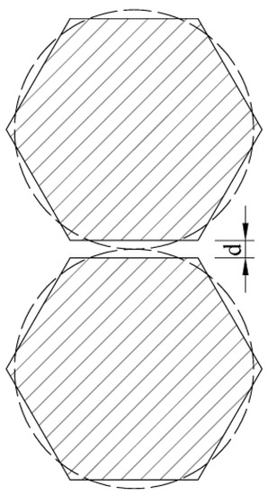
Figure 12.
Quantified inter-strand distance.
According to the literature analysis, currently, there are four methods for controlling the inter-strand distance in the main cable erection process, as shown in Figure 13. The first method is that the inter-strand distance is controlled according to the principle of “half approaching, half separation”. Nevertheless, it is difficult to achieve due to the existence of errors, and new reference strands must be added [85]. The second approach is to raise all the strands to a particular height [57]. The third method is to lift all the general strands as a whole to a specific height [86], and the fourth approach is to lift all the general strands to a specific height over the adjacent layer [65,84]. From the above, there is no unified control or evaluation standard for cable erection. The main reason is that the cable erection alignment is sensitive to error factors. Complex influencing factors and an irreversible erection process make it difficult to form a unified and accurate control method.
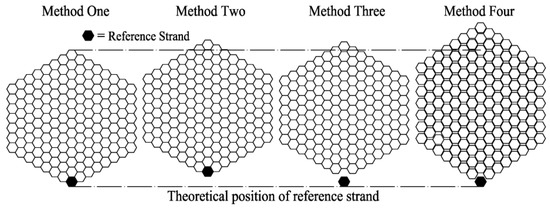
Figure 13.
Various control methods of the inter-strand distance.
3.3. Other Control Technologies
Although strand manufacturing accuracy and overall quality can meet the requirements of cable shape control, there are some studies and attempts to improve the accuracy of cable strand production and to simplify the manufacturing process. For this purpose, Zhao et al. [87] invented an approach to control the manufacturing accuracy of cable strands by using a ruler wire. This methodology exploited a ruler wire to measure the standard wire in cable strands, which reduced the discreteness of deviation in the traditional production process of standard wire between cable strands. However, this method is very dependent on the standard wire, and once the standard wire deviates, it leads to more serious consequences. Dan [88] developed a segmental suspension length measurement method to control the length of the cable, that is, when the cable strand was suspended freely, the length of the strand can be indirectly measured by controlling the alignment of the suspended strand. This approach can eliminate the influence of the elastic modulus and the steel wire diameter error on the stress-free cable length, and avoid the problem of artificial tension in traditional methods. However, this method has high requirements for manufacturing sites and is not used in practical engineering.
Additionally, Wang et al. [89] suggested a novel lateral bracing-based method (LBM), which solved the problem of 3D curved cable configuration transformation for spatial suspension bridges. This is also the embodiment of advanced construction methods in the main cable erection process.
To sum up, both the AS method and the PPWS method are focused on new technology, new equipment, and high-strength materials. Although the characteristics of the AS and PPWS methods are different, the adjustment of sag is the key to controlling the cable shape in these two approaches. The improved cable adjustment formula makes the cable strand erection calculation more efficient and accurate. The use of relative reference strands is the mainstream method to ensure the quality of erection, but there are also interesting methods such as the use of the ruler cable and mark method to erect cable strands, which enriches the means of cable strand erection. The measurement method based on machine vision undoubtedly provides a new idea for construction measurement. Although the relevant specifications stipulate the deviation range of cable erection, the error control standards of specific projects are still not uniform. However, quantifying the cable spacing to achieve cable pre-lifting is a commonly used method in current projects, but the quantitative values and control methods are different. In addition, the cable strand manufacturing and temporary construction equipment were studied to ensure erection accuracy. The above exploration undoubtedly promotes the development of the main cable shape control of suspension bridges.
4. Construction Control Analysis of the Main Cable Shape
Different from other bridge types, the main cable shape cannot realize the design alignment through the tracking adjustment of the construction stage. To ensure that the main cable shape finally reaches the expectation, reliable calculation parameters, accurate calculation methods, and strict construction quality control must be employed. The following is discussed from two aspects: parameter sensitivity analysis and the construction process analysis method.
- (1)
- Parameter sensitivity analysis
Parameter sensitivity analysis is a crucial approach to enhance construction control accuracy, which can help engineers to accurately grasp the main factors affecting the main cable shape and their influence degree. An analysis of the parameters influencing the main cable’s condition on a self-anchored suspension bridge was performed by Sun et al., using the finite element model [13]. The main cable configuration for various constructional conditions at any temperature was evaluated by Zhang et al. [76], using an engineering example. The average temperature sensitivity values for every hanging point elevation on the main span cable in different constructional conditions are compared in Figure 14. The obtained results reveal that the free cable’s temperature sensitivity value is higher than the reference strand’s, and that it is similar to the finished bridge state’s, but the former is marginally higher than the latter. Subsequently, the constructional factors of a three-tower double-cable suspension bridge with two asymmetric main spans were analyzed using the same method [90]. Further, Jia et al. [11] conducted parameter analysis on the triple-tower suspension bridge’s static performance using a finite element model. Li [91] investigated the effects of temperature, saddle location, and the main cable’s elastic modulus on the free cable shape on basis of a highway-railway suspension bridge. The results showed that the saddle mileage had a more significant influence than the saddle elevation on the elevation of the main cable, and the main cable’s elastic modulus had a much bigger impact on the middle span’s elevation compared with the side span. Additionally, under the condition of free cables, the relationship between temperature, and the mid-span and side span elevation was quite close.
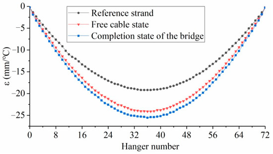
Figure 14.
Comparison of the average temperature sensitivity values for every hanging point elevation on the main span cable under various constructional conditions.
The parameter sensitivity analysis in the above literature is deterministic, that is, when an input parameter has a small perturbation, the quantitative relationship between the system output and the system input can be obtained. However, the randomness analysis can more properly reflect the fundamental traits of the structure. Using the quantitative findings from finite element analysis during the construction, Cho et al. [92] quantified and evaluated the uncertainty of main cable stress and girder deflection in the key construction stages of an illustrated suspension bridge, but did not analyze the main cable shape. The uncertainty analysis of the main cable shape during the construction period has not been reported. Most of the research focuses on the change law of the structure in the finished bridge state [93,94].
- (2)
- Construction process analysis method
The construction process analysis method can be divided into the FEM and analytical method. Based on the numerical iterations and FEM, a self-anchored suspension bridge interactive analysis framework (Figure 15) was constructed by Wang et al. [95]. The framework was based on the stress-free assembly format (Figure 16), which avoids reliance on the forward iteration calculation, and had a high computational efficiency and good convergence. Any specific construction phase can be efficiently analyzed. Li et al. [1] constructed a modified medium model to determine the suspension bridge performance based on the complementary energy principle and variational calculus, which can more thoroughly take into account the deformation of suspension bridges during construction. In terms of construction process analysis, by using data-driven design concepts and BIM authoring, Dang et al. [96] established a master digital model of a suspension bridge, which integrated both the geometric and mechanical models of the suspension bridge system. The geometric control and safety control of components in the construction process can be realized.
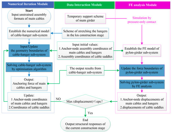
Figure 15.
Interactive framework.
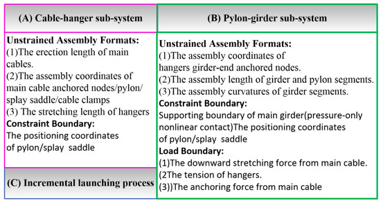
Figure 16.
The stress-free assembly formats, constraint boundaries, and loads.
In summary, compared with the traditional earth-anchored suspension bridge, the self-anchored suspension bridge, the three-tower suspension bridge, and the road-rail suspension bridge have special mechanical properties. At present, the parameter sensitivity analysis of the main cable shape is mainly based on the above three bridge types. However, the parameter sensitivity analysis for the main cable shape is essentially based on the deterministic analysis of a single variable. The formation process of the error during the main cable’s erection is basically the result of the combined action of multiple error factors, but there are few investigations on the multi-factor coupling random analysis of the main cable shape. The emergence of a new construction control analysis method can efficiently and accurately complete the construction stage analysis. The introduction of BIM technology in the construction control analysis process can control the construction process from three aspects: model interaction, data integration, and safety evaluation.
5. Conclusions
The main cable erection and alignment control are the key problems in the construction of the upper structure of the suspension bridge. The key points for controlling the main cable shape include calculation theory, erection technology, and shape control. This paper reviews the research progress in the main cable shape control, from the aspects of main cable shape-finding, construction control technology, and construction control analysis.
(1) Concerning the main cable shape-finding, both the analytical method and FEM focus on spatial cable suspension bridges and three-tower suspension bridges, which have special mechanical characteristics compared with traditional suspension bridges. Although the SCM and its derivative methods are the mainstream methods for shape-finding, there are also some new methods that are different from the SCM, which enrich the means of main cable shape-finding. The introduction of an intelligent optimization algorithm in the shape-finding process can greatly improve computational efficiency. By introducing the geometric relationship and physical relationship between the saddle and the main cable into the piecewise catenary equation, the main cable shape-finding calculation system was more accurate and perfect. This is despite the complex nonlinear equations being transformed into linearized equations in the shape-finding calculations via FEM, and iterative calculations still being required in the process of solving the element stiffness matrix due to the coupling of equations between the elements. The penalty factor search algorithm and the whole mechanical analysis method can improve the computational efficiency. Although the principle of simulating a cable saddle structure by a rod element is simple, the modeling process is complex and the accuracy is insufficient. The cable saddle element can efficiently analyze the influence of the cable saddle on the main cable, and the calculation accuracy is better than that of the rod element. It is a good idea to combine the analytical method with FEM to analyze the main cable shape, which can take advantage of the respective advantages of the two methods.
The future research attentions are still focused on the application and improvement of the existing calculation methods, particularly in the calculation efficiency and refined analysis. However, these specific algorithms and elements are not extensively embedded in analytical software that is commonly utilized in current engineering practice. A large number of advanced calculation methodologies should be effectively applied to practical engineering.
(2) Regarding the construction control technology, the constructional approaches of the main cable and the general principle of strand sag adjustment are summarized. Both the AS method and the PPWS method are focused on new technology, new equipment, and high-strength materials, which undoubtedly promote the rapid improvement of the suspension bridge construction level. The improved cable adjustment formula makes the cable strand erection calculation more efficient and accurate. The use of relative reference strands is the mainstream method for ensuring the quality of erection, but there are also interesting methods such as the use of the ruler cable and the mark method to erect cable strands, which enriches the means of cable strand erection. The measurement method based on machine vision undoubtedly provides a new idea for construction measurement. Although the relevant specifications stipulate the deviation range of cable erection, the error control standards of specific projects are still not uniform. However, quantifying the cable spacing to achieve cable pre-lifting is a commonly used method in current projects, but the quantitative values and control methods are different.
Exploring new approaches of cable strand erection with high efficiency, high precision, and good anti-interference capability still represent the crucial directions of the future research. Advanced measurement technology in the health monitoring of the operation stage can be introduced into the construction stage. The current main cable construction methodologies and control indexes are essentially empirical. The establishment of a unified shape control and evaluation standard can enhance the construction quality and standardize the construction.
(3) In terms of the construction control analysis, the parameter sensitivity analysis of the main cable shape is mainly aimed at the self-anchored suspension bridge, the three-tower suspension bridge, and the road-rail suspension bridge. However, the main cable shape’s parameter sensitivity analysis is primarily based on the deterministic analysis of a single factor, and then the research should focus on multi-factor coupling random analysis. The emergence of the new construction control analysis method can efficiently and accurately complete the construction stage analysis, and especially the introduction of BIM technology in the construction control analysis process, which can monitor the construction process from three aspects: model interaction, data integration, and safety evaluation. It is of great significance to develop an intelligent control analysis system involving multiple factors and the full process.
Author Contributions
Conceptualization, P.H. and C.L.; search and analysis, C.L.; writing—original draft preparation, C.L.; supervision, P.H. All authors have read and agreed to the published version of the manuscript.
Funding
This research was supported by the National Key R&D Program of China (Funded by P.H., grant number 2019YFB1600702).
Institutional Review Board Statement
The study did not require ethical approval.
Informed Consent Statement
Not applicable.
Data Availability Statement
The data are contained within the article.
Conflicts of Interest
The authors declare no conflict of interest.
References
- Li, T.; Liu, Z. An improved continuum model for determining the behavior of suspension bridges during construction. Autom. Constr. 2021, 127, 103715. [Google Scholar] [CrossRef]
- Wang, X.; Wang, Y.; Zhu, P.; Zhang, X.; Wang, H.; He, Y. Experimental and numerical investigations of uhss wire main cables for suspension bridges. Structures 2022, 38, 1582–1594. [Google Scholar] [CrossRef]
- Wang, Y.G. Virtual trial assembly of steel structure based on bim platform. Autom. Constr. 2022, 141, 104395. [Google Scholar] [CrossRef]
- Zhou, X.; Zhang, X. Thoughts on the development of bridge technology in china. Engineering 2019, 5, 1120–1130. [Google Scholar] [CrossRef]
- Kim, H.S.; Kim, Y.J.; Chin, W.J.; Yoon, H. Development of highly efficient construction technologies for super long span bridge. Engineering 2013, 5, 629–636. [Google Scholar] [CrossRef]
- Apaydin, N.M.; Bas, S. Long-span orthotropic steel deck bridges of turkey. IOP Conf. Ser. Mater. Sci. Eng. 2018, 419, 012023. [Google Scholar] [CrossRef]
- Wang, S.; Zhou, Z.; Gao, Y.; Huang, Y. Analytical calculation method for the preliminary analysis of self-anchored suspension bridges. Math. Probl. Eng. 2015, 2015, 918649. [Google Scholar] [CrossRef]
- Thai, H.T. Advanced analysis of multi-span suspension bridges. J. Constr. Steel Res. 2013, 90, 29–41. [Google Scholar] [CrossRef]
- Son, Y.; Lee, C.; Yoo, D.; Kim, J.; Choi, J. Cheon-sa bridge—The first sea crossing multi-span suspension bridge. Struct. Eng. Int. 2021, 31, 431–434. [Google Scholar] [CrossRef]
- Wang, R. Study of Key Construction scheme for long-span suspension bridge in harsh mountainous region of plateau. Bridge Constr. 2019, 49, 108–113. [Google Scholar]
- Jia, L.; Lin, Z.; Xiao, R.; Jiang, Y. Parameter effects on the mechanical performance of triple-tower four-span suspension bridges. Adv. Struct. Eng. 2018, 21, 256–269. [Google Scholar] [CrossRef]
- Sun, J.Y.; Yin, C.Z.; Ma, Z.B. Object-oriented computer-aided analysis for construction control of anchored suspension bridge. AMM 2014, 543–547, 3977–3981. [Google Scholar] [CrossRef]
- Sun, Y.M.; He, X.D.; Li, W.D. Influential parameter study on the main-cable state of self-anchored suspension bridge. KEM 2014, 619, 99–108. [Google Scholar] [CrossRef]
- Hanaor, A. Prestressed pin-jointed structures—Flexibility analysis and prestress design. Comput. Struct. 1988, 28, 757–769. [Google Scholar] [CrossRef]
- Kim, H.K.; Lee, M.J.; Chang, S.P. Non-linear shape-finding analysis of a self-anchored suspension bridge. Eng. Struct. 2002, 24, 1547–1559. [Google Scholar] [CrossRef]
- Jung, M.R.; Min, D.J.; Kim, M.Y. Nonlinear analysis methods based on the unstrained element length for determining initial shaping of suspension bridges under dead loads. Comput. Struct. 2013, 128, 272–285. [Google Scholar] [CrossRef]
- Zhang, W.; Yang, C.; Tian, G.; Liu, Z. Analytical assessment of main cable shape for three-pylon suspension bridge with unequal main-span lengths: Thermal effect consideration. J. Bridge Eng. 2020, 25, 04019136. [Google Scholar] [CrossRef]
- Buonopane, S.; Billington, D. Theory and history of suspension bridge design from 1823 to 1940. J. Struct. Eng. 1993, 119, 954–977. [Google Scholar] [CrossRef]
- Ahmadi-Kashani, K.; Bell, A.J. The analysis of cables subject to uniformly distributed loads. Eng. Struct. 1988, 10, 174–184. [Google Scholar] [CrossRef]
- Jung, M.R.; Min, D.J.; Kim, M.Y. Simplified analytical method for optimized initial shape analysis of self-anchored suspension bridges and its verification. Math. Probl. Eng. 2015, 2015, 923508. [Google Scholar] [CrossRef]
- Tang, M.L. 3D Geometric Nonlinear Analysis of Long-Span Suspension Bridge and Its Software Development. Ph.D. Thesis, Southwest Jiaotong University, Chengdu, China, 2003. [Google Scholar]
- Zheng, J.J.; Ding, S.; Zhou, H.B.; Zhang, J.L.; Piao, J.M. Least squares calculation with Marquardt correction for spatial cable shape of suspension bridge. J. Beijing Jiaotong Univ. 2016, 40, 26–30. [Google Scholar]
- Wu, Y.X.; Zhou, J.T.; Sun, M.; Tian, Z.S.; Wang, Z. Geometry calculation method for main cables of completed suspension bridge with irregular spatial cable planes. Bridge Constr. 2020, 50, 37–43. [Google Scholar]
- Deng, X.K.; Xu, G.Y. New method for calculating main cable of suspension bridge. J. China Railw. Soc. 2019, 41, 133–141. [Google Scholar]
- Liu, C.; Gao, Z. A method for determining cable shape of a self-anchored suspension bridge based on an overall mechanical analysis. J. Tongji Univ. (Nat. Sci.) 2020, 48, 1–6. [Google Scholar]
- Liu, Z.; Zhan, H.P.; Zhu, Y. Modified force density method for form-finding of main cable of suspension bridges. J. Tongji Univ. (Nat. Sci.) 2022, 50, 351–358. [Google Scholar]
- Chen, Z.; Cao, H.; Ye, K.; Zhu, H.; Li, S. Improved particle swarm optimization-based form-finding method for suspension bridge installation analysis. J. Comput. Civ. Eng. 2015, 29, 04014047. [Google Scholar] [CrossRef]
- Cao, H.; Zhou, Y.-L.; Chen, Z.; Wahab, M.A. Form-finding analysis of suspension bridges using an explicit iterative approach. Struct. Eng. Mech. 2017, 62, 85–95. [Google Scholar] [CrossRef]
- Cao, H.; Qian, X.; Chen, Z.; Zhu, H. Layout and size optimization of suspension bridges based on coupled modelling approach and enhanced particle swarm optimization. Eng. Struct. 2017, 146, 170–183. [Google Scholar] [CrossRef]
- Wang, S.; Zhou, Z.; Wen, D.; Huang, Y. New method for calculating the preoffsetting value of the saddle on suspension bridges considering the influence of more parameters. J. Bridge Eng. 2016, 21, 06016010. [Google Scholar] [CrossRef]
- Gao, Q.F.; Hong, N.D.; Guo, B.Q.; Liu, Y.; Ma, Q.L. Calculation method for length of main cable at saddle in long-span suspension bridge. J. Harbin Inst. Technol. 2020, 52, 57–62. [Google Scholar]
- Luo, L.F.; Shan, D.S.; Chen, F.M.; Chen, P.Y. High-precision calculation method for configuration of completed suspension bridges with pin-connected cable clamps. Eng. Mech. 2021, 38, 133–144. [Google Scholar]
- Deng, X.; Deng, H. Improved algorithm to determine the composite circular curve splay saddle position. Struct. Eng. Int. 2022, 33, 141–146. [Google Scholar] [CrossRef]
- Li, T.; Liu, Z.; Zhang, W. Analysis of suspension bridges in construction and completed status considering the pylon saddles. Eur. J. Environ. Civ. En. 2022, 26, 4280–4295. [Google Scholar] [CrossRef]
- Sun, Y.; Zhu, H.P.; Xu, D. A specific rod model based efficient analysis and design of hanger installation for self-anchored suspension bridges with 3d curved cables. Eng. Struct. 2016, 110, 184–208. [Google Scholar] [CrossRef]
- Ozdemir, H. A finite element approach for cable problems. Int. J. Solids Struct. 1979, 15, 427–437. [Google Scholar] [CrossRef]
- Yang, Y.B.; Tsay, J.Y. Two-node catenary cable element with rigid-end effect and cable shape analysis. Int. J. Str. Stab. Dyn. 2011, 11, 563–580. [Google Scholar] [CrossRef]
- Chung, K.S.; Cho, J.Y.; Park, J.I.; Chang, S.-P. Three-dimensional elastic catenary cable element considering sliding effect. J. Eng. Mech. 2011, 137, 276–283. [Google Scholar] [CrossRef]
- Editorial Department of China Journal of Highway and Transport. An academic research summary on china highway and transport: 2012. China J. Highw. Transp. 2012, 25, 2–50. [Google Scholar]
- Kim, K.S.; Lee, H.S. Analysis of target configurations under dead loads for cable-supported bridges. Comput. Struct. 2001, 79, 2681–2692. [Google Scholar] [CrossRef]
- Kim, H.K.; Kim, M.Y. Efficient combination of a tcud method and an initial force method for determining initial shapes of cable-supported bridges. Int. J. Steel Struct. 2012, 12, 157–174. [Google Scholar] [CrossRef]
- Kim, M.Y.; Jung, M.R.; Attard, M.M. Unstrained length-based methods determining an optimized initial shape of 3-dimensional self-anchored suspension bridges. Comput. Struct. 2019, 217, 18–35. [Google Scholar] [CrossRef]
- Sun, Y.; Zhu, H.P.; Xu, D. New method for shape finding of self-anchored suspension bridges with three-dimensionally curved cables. J. Bridge Eng. 2015, 20, 04014063. [Google Scholar] [CrossRef]
- Coda, H.B.; de Oliveira Silva, A.P.; Paccola, R.R. Alternative active nonlinear total lagrangian truss finite element applied to the analysis of cable nets and long span suspension bridges. Lat. Am. J. Solids Struct. 2020, 17, e268. [Google Scholar] [CrossRef]
- Wang, H.; Qin, S. Shape finding of suspension bridges with interacting matrix. Eur. J. Environ. Civ. Eng. 2016, 20, 831–840. [Google Scholar] [CrossRef]
- Li, C.; He, J.; Zhang, Z.; Liu, Y.; Ke, H.; Dong, C.; Li, H. An improved analytical algorithm on main cable system of suspension bridge. Appl. Sci. 2018, 8, 1358. [Google Scholar] [CrossRef]
- Zhou, Y.; Chen, S. Iterative nonlinear cable shape and force finding technique of suspension bridges using elastic catenary configuration. J. Eng. Mech. 2019, 145, 04019031. [Google Scholar] [CrossRef]
- Zhu, W.; Ge, Y.; Fang, G.; Cao, J. A novel shape finding method for the main cable of suspension bridge using nonlinear finite element approach. Appl. Sci. 2021, 11, 4644. [Google Scholar] [CrossRef]
- Chen, Z.; Cao, H.; Zhu, H. An iterative calculation method for suspension bridge’s cable system based on exact catenary theory. Balt. J. Road Bridge Eng. 2013, 8, 196–204. [Google Scholar] [CrossRef]
- Fan, L.C.; Pan, Y.R.; Du, G.H. Study on the fine method of calculating the erection-parameters of long-span suspension bridges. China Civil Eng. J. 1999, 32, 20–25. [Google Scholar]
- Xu, J.L. Construction Control of Long-Span Bridges; China Communications Press: Beijing, China, 2000. [Google Scholar]
- Zhou, G.; Li, A.; Li, J.; Duan, M.; Xia, Z.; Zhu, L. Determination and implementation of reasonable completion state for the self-anchored suspension bridge with extra-wide concrete girder. Appl. Sci. 2019, 9, 2576. [Google Scholar] [CrossRef]
- Luo, X.H.; Xiao, R.C.; Xiang, H.F. Saddle-cable elements for nonlinear analysis of suspension bridges. China Civil Eng. J. 2005, 38, 47–53. [Google Scholar]
- Qi, D.C. A Refined Analysis Method of Main Cable for Long-Span Suspension Bridge. Ph.D. Thesis, Southwest Jiaotong University, Chengdu, China, 2012. [Google Scholar]
- Li, J.; Feng, D.; Li, A.; Yuan, H. Determination of reasonable finished state of self-anchored suspension bridges. J. Cent. South Univ. 2016, 23, 209–219. [Google Scholar] [CrossRef]
- Zhang, W.; Li, T.; Shi, L.; Liu, Z.; Qian, K. An iterative calculation method for hanger tensions and the cable shape of a suspension bridge based on the catenary theory and finite element method. Adv. Struct. Eng. 2019, 22, 1566–1578. [Google Scholar] [CrossRef]
- Matsuzaki, M.; Uchikawa, C.; Mitamura, T. Advanced fabrication and erection techniques for long suspension bridge cables. J. Constr. Eng. M. 1990, 116, 112–129. [Google Scholar] [CrossRef]
- Konishi, I. Latest developments on prefabricated parallel wire strand in japan. Ann. Ny. Acad. Sci. 1980, 352, 55–70. [Google Scholar] [CrossRef]
- Liu, X.H.; Xian, J.P.; Jin, C.; Li, S.; Guo, R. Construction techniques for main cable erection of suspension bridge by air spinning method. Technol. Highw. Transp. 2021, 37, 94–99. [Google Scholar]
- Moon, J.; Jeong, S.; Choi, H. Yi sun-sin bridge: Several unique features on the cable erection procedure. In Proceedings of the 18th Congress of IABSE: Innovative Infrastructures—Towards Human Urbanism, Seoul, Republic of Korea, 19–21 September 2012. [Google Scholar]
- Kim, J.; Lee, M.; Kim, J.; Choi, J. The recent cable and deck erection methods applied in various types of suspension bridges in korea. In Proceedings of the IABSE Conference—Structural Engineering: Providing Solutions to Global Challenges, Geneva, Switzerland, 23–25 September 2015. [Google Scholar]
- Yoo, H.; Seo, J.W.; Lee, S.H.; Park, Y.H. High-strength prefabricated parallel wire strand for ulsan harbor bridge and its mass production system in Korea. Struct. Eng. Int. 2014, 24, 293–297. [Google Scholar] [CrossRef]
- Kim, J.; Chung, K.; Yoon, J.; Lee, S. Erection of catwalk rope and main cable of jeokgeum bridge. In Proceedings of the 37th IABSE Symposium: Engineering for Progress, Nature and People, Madrid, Spain, 3–5 September 2014. [Google Scholar]
- Chen, Y.; Wei, W.; Dai, J. The key quality control technology of main cable erection in long-span suspension bridge construction. IOP Conf. Ser. Earth Environ. Sci. 2017, 61, 012124. [Google Scholar] [CrossRef]
- Zhang, W.; Liu, Z.; Xu, S. Jindong bridge: Suspension bridge with steel truss girder and prefabricated RC deck slabs in China. Struct. Eng. Int. 2019, 29, 315–318. [Google Scholar] [CrossRef]
- JTG/T 3650-2020; Technical Specifications for Construction of Highway Bridges and Culverts. Standards Press of China: Beijing, China, 2020.
- Zhang, J.Q.; Xu, Y.; Xian, Z.H. Study on grey forecasting control for construction of suspension bridge cables. J. Xi’an Highw. Univ. 1997, 17, 51–55. [Google Scholar]
- He, J.; Li, C.; Ke, H.; Liu, Y.; Zhang, Y.; Dong, C.; Li, H.; Zhang, Z. A simplified calculation method of length adjustment of datum strand for the main cable with small sag. Adv. Civ. Eng. 2019, 2019, 6075893. [Google Scholar] [CrossRef]
- Tan, H.M.; Yuan, S.H.; Xiao, R.C. The adjustment of datum strand of long-span suspension bridges. China Railw. Sci. 2010, 31, 38–43. [Google Scholar]
- Wang, Z.B. Construction monitoring techniques for superstructure of Ying Wuzhou Yangtze River Bridge in Wuhan. Bridge Constr. 2018, 48, 100–105. [Google Scholar]
- Deng, X.K.; Sun, J. Improved method for calculation of datum strand adjustment of suspension bridge. J. Chongqing Jiaotong Univ. (Nat. Sci.) 2021, 40, 90–95. [Google Scholar]
- Li, H.; Xian, Z.Q.; Shen, L.C.; Wen, W.; Dong, T. Method of adjusting cable strand sagging for suspension bridge of Runyang Bridge. Bridge Constr. 2004, 4, 36–39. [Google Scholar]
- Lu, W.; Gan, H.; Yu, Y.Q.; Tang, M.L.; Li, R.Z.; Qian, J.N. The adjustment technique for strand of main cable of Xi Houmen Bridge. Steel Construction. 2010, 25, 74–78. [Google Scholar]
- Huang, C.; Wang, Y.; Xu, S.; Shou, W.; Peng, C.; Lv, D. Vision-based methods for relative sag measurement of suspension bridge cables. Buildings 2022, 12, 667. [Google Scholar] [CrossRef]
- Tang, M.L.; Xu, G.T.; Li, C.; Tan, F.L.; Tang, Z.B.; Tan, G.Y.; Chen, X.Y.; Dong, J.H.; Zhang, X.B.; Wang, H.L. A Method Erection Method of Main Cable Strand Mark of Suspension Bridge Based on Multi-Standard Wire; SIPO: Beijing, China, 2019. [Google Scholar]
- Zhang, W.; Tian, G.; Liu, Z. Analytical study of uniform thermal effects on cable configuration of a suspension bridge during construction. J. Bridge Eng. 2019, 24, 04019104. [Google Scholar] [CrossRef]
- Matsumoto, K.; Arturo Linan Panting, C.; Kitratporn, N.; Takeuchi, W.; Nagai, K.; Iwasaki, E. Performance assessment using structural analysis and spatial measurement of a damaged suspension bridge: Case study of twantay bridge, myanmar. J. Bridge Eng. 2018, 23, 05018008. [Google Scholar] [CrossRef]
- Wang, X.; Zhao, Q.; Xi, R.; Li, C.; Li, G.; Li, L. Review of bridge structural health monitoring based on gnss: From displacement monitoring to dynamic characteristic identification. IEEE Access 2021, 9, 80043–80065. [Google Scholar] [CrossRef]
- Wang, C.; Hua, X.; Huang, Z.; Tang, Y.; Chen, Z. Post-critical behavior of galloping for main cables of suspension bridges in construction phases. J. Fluid. Struct. 2021, 101, 103205. [Google Scholar] [CrossRef]
- Birdsall, B. Discussion of “Advanced fabrication and erection techniques for long suspension bridge cables” by minora matsuzaki, chihiko uchikawa, and takeshi mitamura (march, 1990, vol. 116, no. 1). J. Constr. Eng. Manag. 1992, 118, 200–205. [Google Scholar] [CrossRef]
- Bi, X.D.; Feng, Y.X.; Yang, M. Technical improvement and construction of main cable strand erection of Ma Anshan Bridge. J. Highw. Transp. Res. Dev. (Appl. Technol.) 2014, 10, 215–218. [Google Scholar]
- Li, H. The main cable erection technology for preventing the main cable of suspension bridge from bulging and twisting. Chin. Overseas Architect. 2015, 177–178. [Google Scholar] [CrossRef]
- Liao, C.; Zhang, N.L.; Yi, J.W. The main suspension cable erection technology of Aizhai Bridge. Constr. Technol. 2013, 42, 5–8. [Google Scholar]
- Feng, C.B. Control techniques for superstructure construction of Wu Fengshan Yangtze River Bridge. Bridge Constr. 2020, 50, 99–104. [Google Scholar]
- Xu, T.; Zhang, Y.S.; Zeng, X. Influence of construction error on suspender length of suspension bridges. J. Chongqing Jiaotong Univ. (Nat. Sci.) 2013, 32, 915–917. [Google Scholar]
- Zhao, Y. Research on Main Cable Control and Poisson Effect Involved in Suspension Bridge. Master’s Thesis, Chang’an University, Xi’an, China, 2016. [Google Scholar]
- Zhao, J.; Xue, H.J.; Zhou, Z.B.; Dai, Z.F.; Gao, M. A Method to Control the Manufacture of Cable Strands by Using a Ruler Wire; SIPO: Beijing, China, 2010. [Google Scholar]
- Dan, Q.L. Alignment Controlling Theory and Application of Bridge Structure Formed in Stages Based on Unstressed State Control Method. Ph.D. Thesis, Southwest Jiaotong University, Chengdu, China, 2017. [Google Scholar]
- Wang, X.; Frangopol, D.M.; Dong, Y.; Lei, X.; Zhang, Y. Novel technique for configuration transformation of 3d curved cables of suspension bridges: Application to the dongtiao river bridge. J. Perform. Constr. Facil. 2018, 32, 04018045. [Google Scholar] [CrossRef]
- Zhang, W.; Yang, C.; Chang, J. Cable shape and construction parameters of triple-tower double-cable suspension bridge with two asymmetrical main spans. J. Bridge Eng. 2021, 26, 04020127. [Google Scholar] [CrossRef]
- Li, B. Control techniques for cable system construction of Wu Fengshan Yangtze River Bridge. Bridge Constr. 2021, 51, 119–126. [Google Scholar]
- Cho, T.; Kim, T.S. Probabilistic risk assessment for the construction phases of a bridge construction based on finite element analysis. Finite Elem. Anal. Des. 2008, 44, 383–400. [Google Scholar] [CrossRef]
- Li, J.; Li, A.; Feng, M.Q. Sensitivity and reliability analysis of a self-anchored suspension bridge. J. Bridge Eng. 2013, 18, 703–711. [Google Scholar] [CrossRef]
- An, X.; Gosling, P.D.; Zhou, X. Analytical structural reliability analysis of a suspended cable. Struct. Saf. 2016, 58, 20–30. [Google Scholar] [CrossRef]
- Wang, X.; Wang, H.; Sun, Y.; Mao, X.; Tang, S. Process-independent construction stage analysis of self-anchored suspension bridges. Autom. Constr. 2020, 117, 103227. [Google Scholar] [CrossRef]
- Dang, N.S.; Rho, G.T.; Shim, C.S. A master digital model for suspension bridges. Appl. Sci. 2020, 10, 7666. [Google Scholar] [CrossRef]


Disclaimer/Publisher’s Note: The statements, opinions and data contained in all publications are solely those of the individual author(s) and contributor(s) and not of MDPI and/or the editor(s). MDPI and/or the editor(s) disclaim responsibility for any injury to people or property resulting from any ideas, methods, instructions or products referred to in the content. |
© 2023 by the authors. Licensee MDPI, Basel, Switzerland. This article is an open access article distributed under the terms and conditions of the Creative Commons Attribution (CC BY) license (https://creativecommons.org/licenses/by/4.0/).