


Insertion Torque (IT) and Implant Stability Quotient (ISQ) Assessment in Dental Implants with and without Healing Chambers: A Polyurethane In Vitro Study

 , ,
, , 
 ,
,  ,
, 

Abstract
:1. Introduction
2. Materials and Methods
2.1. Dental Implants
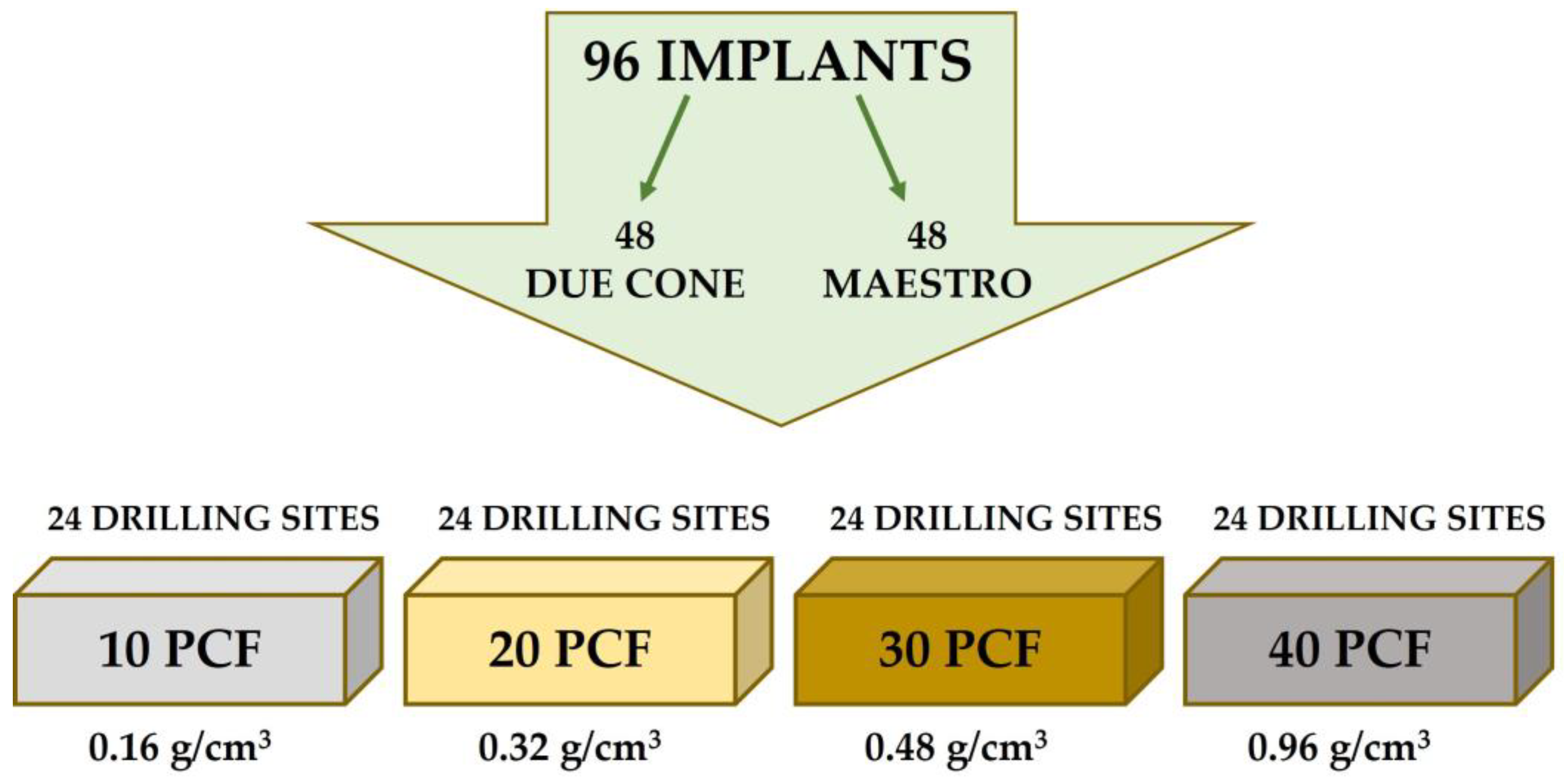
2.2. Experimental Study Design
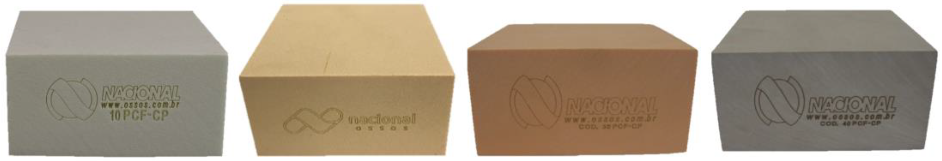
2.3. Polyurethane Block Simulator
2.4. Implant Drill
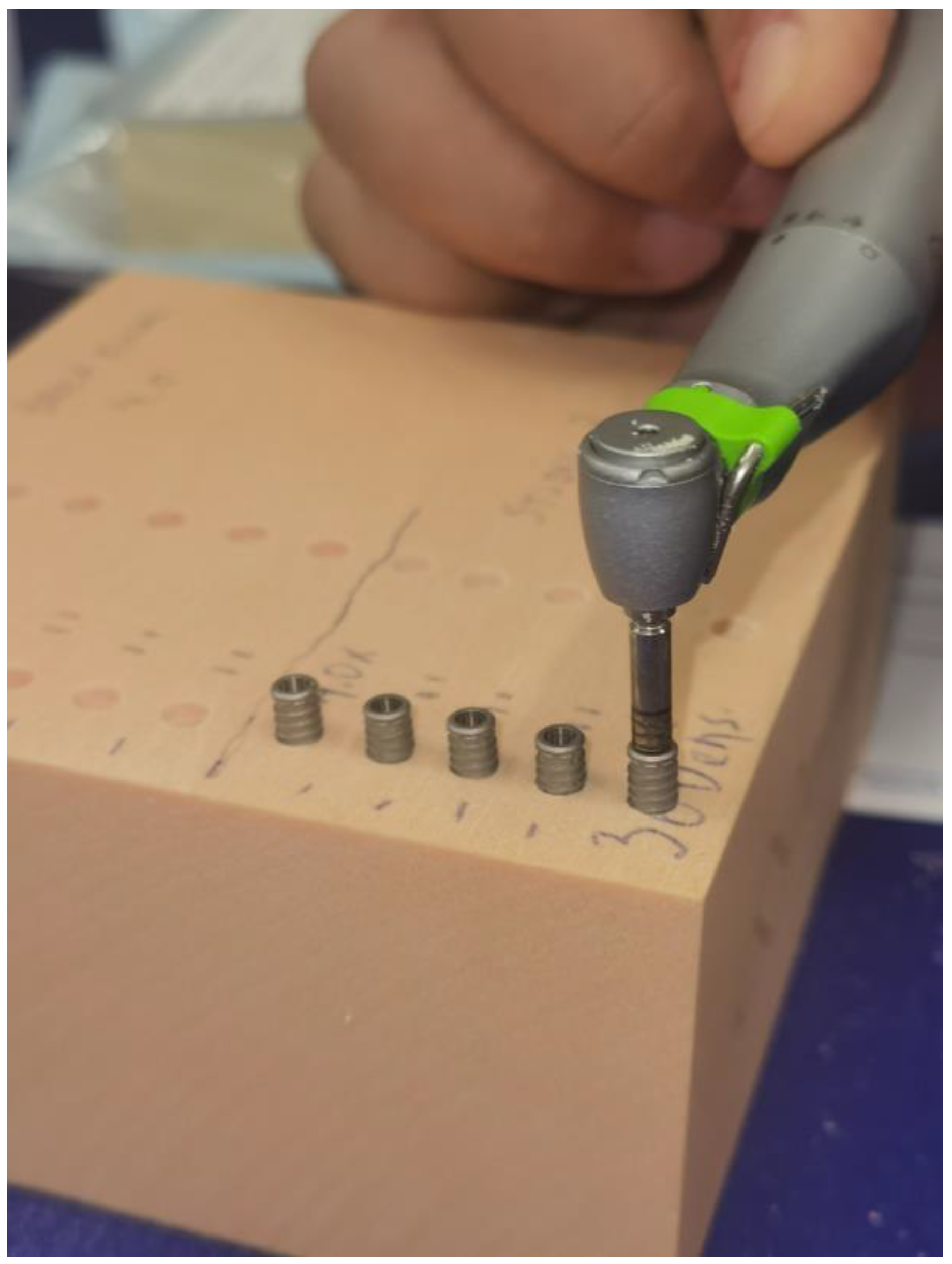
2.5. Insertion Torque (IT) and Removal Torque (RT)
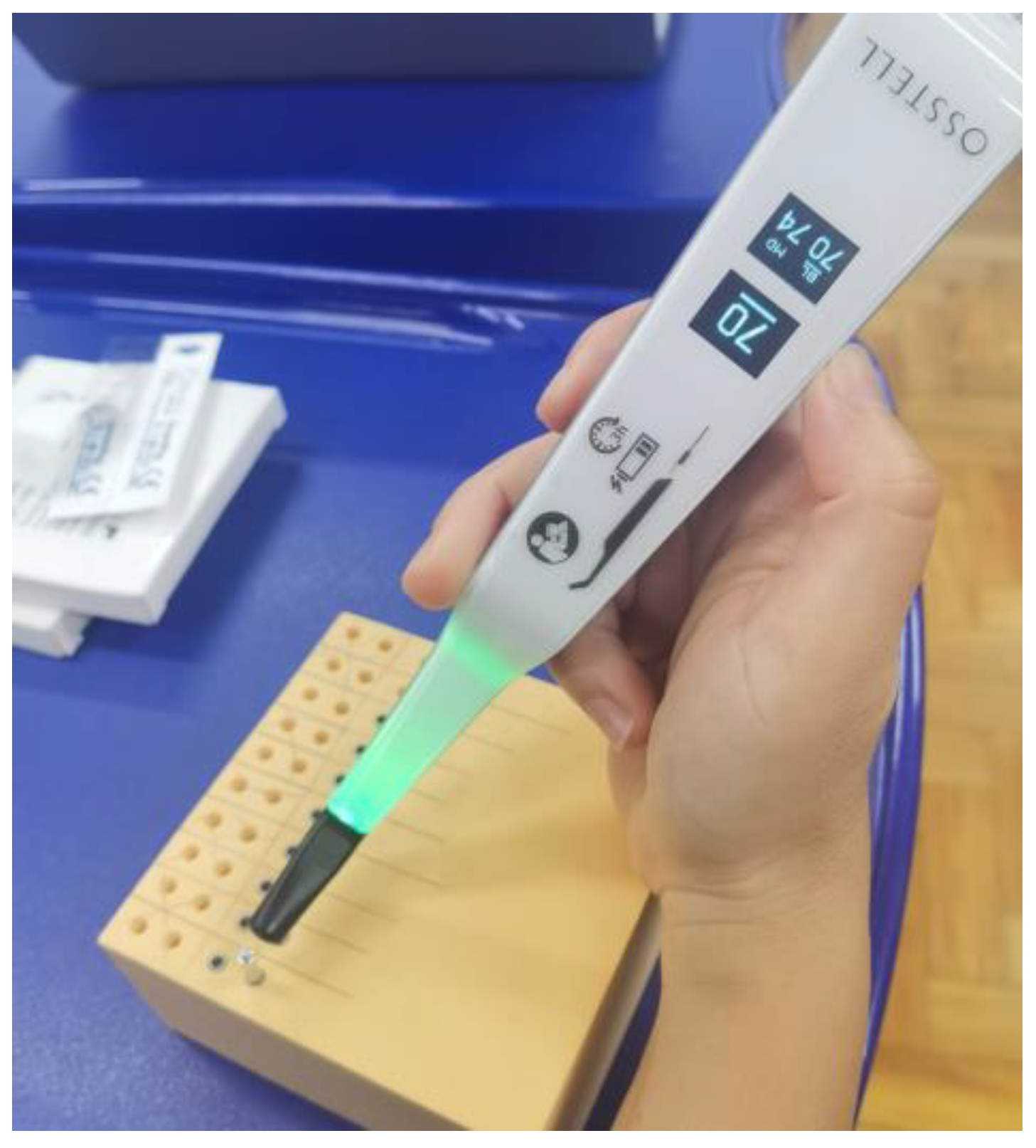
2.6. Resonance Frequency Analysis (RFA)
2.7. Calculation of the Sample Size
2.8. Statistical Analysis
3. Results
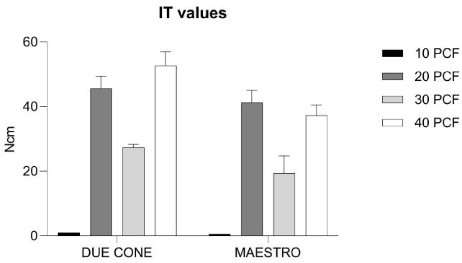
3.1. IT Values
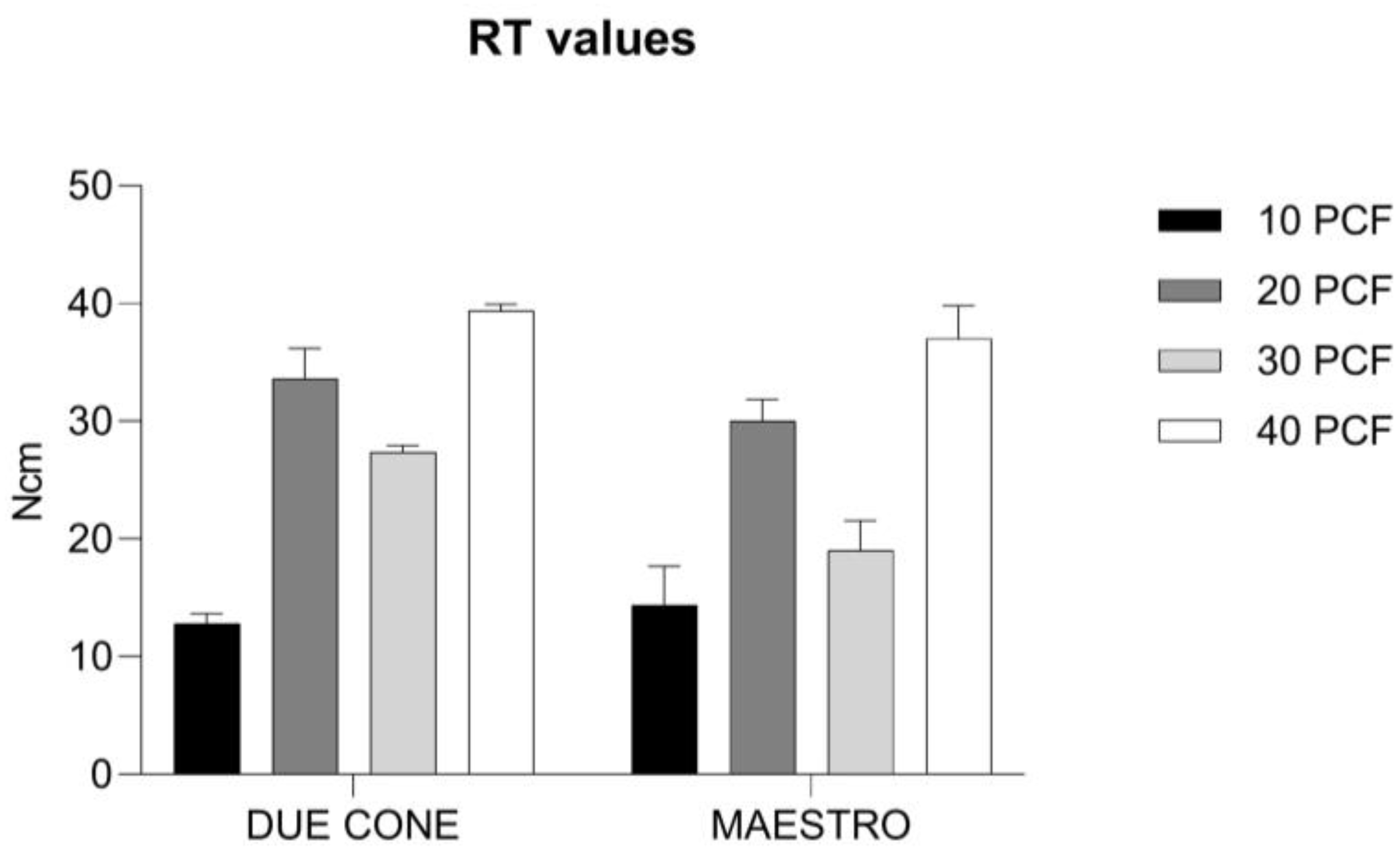
3.2. RT Values
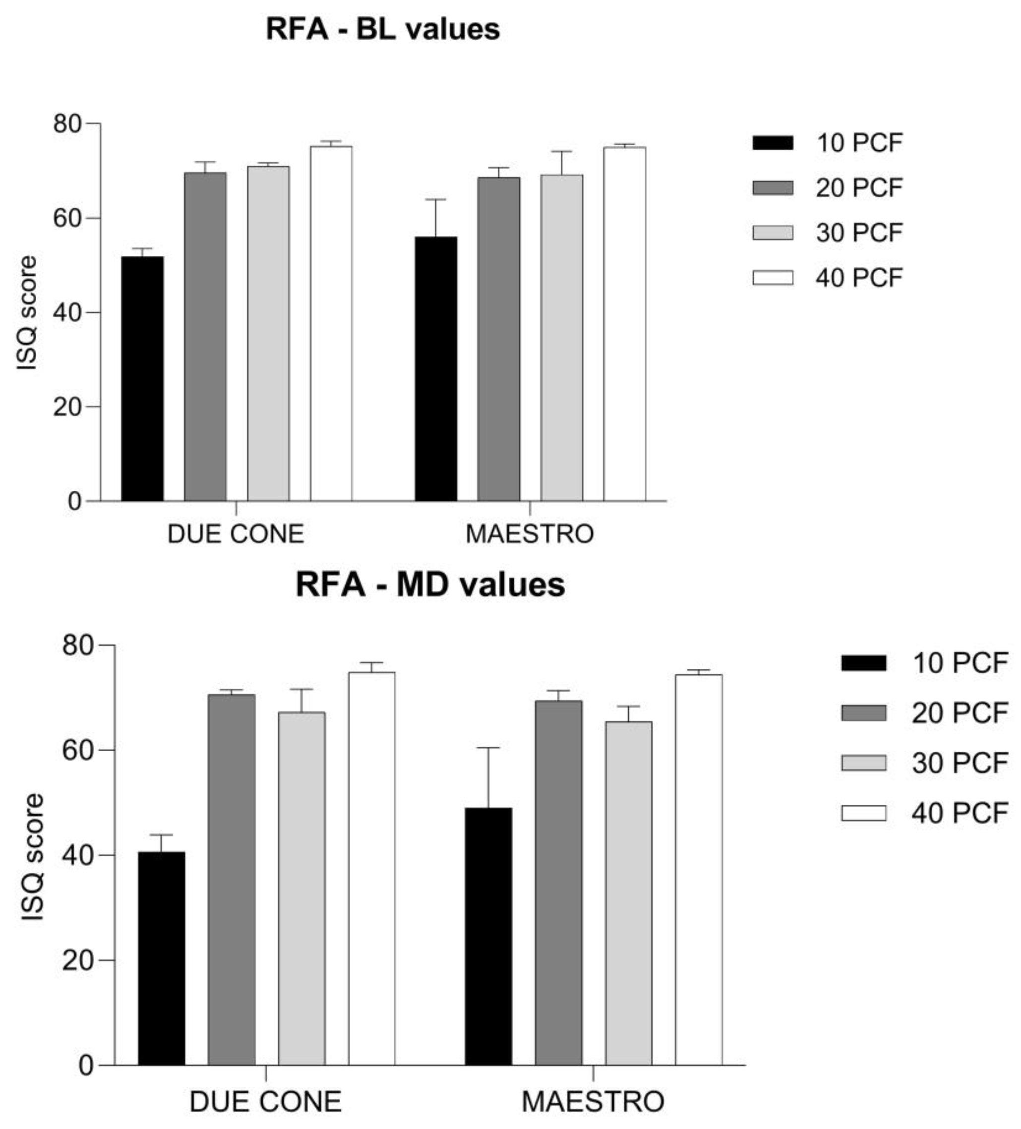
3.3. RFA Values
4. Discussion
5. Conclusions
Author Contributions
Funding
Institutional Review Board Statement
Informed Consent Statement
Data Availability Statement
Acknowledgments
Conflicts of Interest
References
- Gehrke, S.A.; Pérez-Díaz, L.; Mazón, P.; De Aza, P.N. Biomechanical Effects of a New Macrogeometry Design of Dental Implants: An In Vitro Experimental Analysis. J. Funct. Biomater. 2019, 10, 47. [Google Scholar] [CrossRef] [PubMed]
- Coelho, P.G.; Suzuki, M.; Marin, C.; Granato, R.; Gil, L.F.; Tovar, N.; Jimbo, R.; Neiva, R.; Bonfante, E.A. Osseointegration of Plateau Root Form Implants: Unique Healing Pathway Leading to Haversian-Like Long-Term Morphology. Adv. Exp. Med. Biol. 2015, 881, 111–128. [Google Scholar] [CrossRef] [PubMed]
- Gehrke, S.A.; Pereira, G.M.A.; Gehrke, A.F.; Junior, N.D.B.; Dedavid, B.A. Effects of Insertion Torque on the Structure of Dental Implants with Different Connections: Experimental Pilot Study in Vitro. PLoS ONE 2021, 16, e0251904. [Google Scholar] [CrossRef]
- Gehrke, S.A.; Scarano, A.; de Lima, J.H.C.; Bianchini, M.A.; Dedavid, B.A.; De Aza, P.N. Effects of the Healing Chambers in Implant Macrogeometry Design in a Low-Density Bone Using Conventional and Undersized Drilling. J. Int. Soc. Prev. Commun. Dent. 2021, 11, 437–447. [Google Scholar] [CrossRef] [PubMed]
- Scarano, A.; Carinci, F.; Lorusso, F.; Festa, F.; Bevilacqua, L.; Santos de Oliveira, P.; Maglione, M. Ultrasonic vs Drill Implant Site Preparation: Post-Operative Pain Measurement through VAS, Swelling and Crestal Bone Remodeling: A Randomized Clinical Study. Materials 2018, 11, 2516. [Google Scholar] [CrossRef]
- Maglione, M.; Bevilacqua, L.; Dotto, F.; Costantinides, F.; Lorusso, F.; Scarano, A. Observational Study on the Preparation of the Implant Site with Piezosurgery vs. Drill: Comparison between the Two Methods in Terms of Postoperative Pain, Surgical Times, and Operational Advantages. BioMed Res. Int. 2019, 2019, 8483658. [Google Scholar] [CrossRef]
- Romanos, G.E.; Delgado-Ruiz, R.A.; Sacks, D.; Calvo-Guirado, J.L. Influence of the implant diameter and bone quality on the primary stability of porous tantalum trabecular metal dental implants: An in vitro biomechanical study. Clin. Oral Implant. Res. 2018, 6, 649–655. [Google Scholar] [CrossRef]
- Cipollina, A.; Ceddia, M.; Di Pietro, N.; Inchingolo, F.; Tumedei, M.; Romasco, T.; Piattelli, A.; Specchiulli, A.; Trentadue, B. Finite Element Analysis (FEA) of a Premaxillary Device: A New Type of Subperiosteal Implant to Treat Severe Atrophy of the Maxilla. Biomimetics 2023, 8, 336. [Google Scholar] [CrossRef]
- ASTM F1839; Standard Specification for Rigid Polyurethane Foam for Use as a Standard Material for Testing Orthopaedic Devices and Instruments. American Society for Testing and Materials (ASTM): West Conshohocken, PA, USA, 2008. [CrossRef]
- Di Stefano, D.A.; Arosio, P.; Gastaldi, G.; Gherlone, E. The insertion torque-depth curve integral as a measure of implant primary stability: An in vitro study on polyurethane foam blocks. J. Prosthet. Dent. 2018, 5, 706–714. [Google Scholar] [CrossRef]
- Tsolaki, I.N.; Tonsekar, P.P.; Najafi, B.; Drew, H.J.; Sullivan, A.J.; Petrov, S.D. Comparison of osteotome and conventional drilling techniques for primary implant stability: An in vitro study. J. Oral Implant. 2016, 42, 321–325. [Google Scholar] [CrossRef]
- Comuzzi, L.; Tumedei, M.; Di Pietro, N.; Romasco, T.; Heydari Sheikh Hossein, H.; Montesani, L.; Inchingolo, F.; Piattelli, A.; Covani, U. A Comparison of Conical and Cylindrical Implants Inserted in an In Vitro Post-Extraction Model Using Low-Density Polyurethane Foam Blocks. Materials 2023, 16, 5064. [Google Scholar] [CrossRef] [PubMed]
- Misch, C.E. Bone Density: A Key Determinant for Treatment Planning. Contemporary Implant Dentistry, 3rd ed.; Mosby: St. Louis, MO, USA, 2007; pp. 130–146. [Google Scholar]
- Gehrke, S.A.; Cortellari, G.C.; De Oliveira Fernandes, G.V.; Scarano, A.; Martins, R.G.; Cançado, R.M.; Mesquita, A.M.M. Randomized Clinical Trial Comparing Insertion Torque and Implant Stability of Two Different Implant Macrogeometries in the Initial Periods of Osseointegration. Medicina 2023, 59, 168. [Google Scholar] [CrossRef] [PubMed]
- Gehrke, S.A.; Eliers Treichel, T.L.; Pérez-Díaz, L.; Calvo-Guirado, J.L.; Aramburú Júnior, J.; Mazón, P.; De Aza, P.N. Impact of Different Titanium Implant Thread Designs on Bone Healing: A Biomechanical and Histometric Study with an Animal Model. J. Clin. Med. 2019, 8, 777. [Google Scholar] [CrossRef]
- Calvert, K.L.; Trumble, K.P.; Webster, T.J.; Kirkpatrick, L.A. Characterization of commercial rigi d polyurethane foams used as bone analogs for implant testing. J. Mater. Sci. Mater. Med. 2010, 21, 1453–1461. [Google Scholar] [CrossRef]
- Nagaraja, S.; Palepu, V. Comparisons of Anterior Plate Screw Pullout Strength Between Polyurethane Foams and Thoracolum-bar Cadaveric Vertebrae. J. Biomech. Eng. 2016, 138, 104505. [Google Scholar] [CrossRef] [PubMed]
- Al-Tarawneh, S.; Thalji, G.; Cooper, L. Macrogeometric Differentiation of Dental Implant Primary Stability: An In Vitro Study. Int. J. Oral Maxillofac. Implant. 2022, 37, 1110–1118. [Google Scholar] [CrossRef] [PubMed]
- Comuzzi, L.; Tumedei, M.; Covani, U.; Romasco, T.; Petrini, M.; Montesani, L.; Piattelli, A.; Di Pietro, N. Primary Stability Assessment of Conical Implants in Under-Prepared Sites: An In Vitro Study in Low-Density Polyurethane Foams. Appl. Sci. 2023, 13, 6041. [Google Scholar] [CrossRef]
- Greenstein, G.; Cavallaro, J. Implant Insertion Torque: Its Role in Achieving Primary Stability of Restorable Dental Implants. Compend. Contin. Educ. Dent. 2017, 38, 88–96. [Google Scholar]
- Simeone, S.G.; Rios, M.; Simonpietri, J. “Reverse torque of 30 Ncm applied to dental implants as test for osseointegration”—Ahuman observational study. Int. J. Implant. Dent. 2016, 2, 26. [Google Scholar] [CrossRef]
- Meredith, N.; Alleyne, D.; Cawley, P. Quantitative determination of the stability of the implant-tissue interface using resonancefrequency analysis. Clin. Oral Implant. Res. 1996, 7, 261–267. [Google Scholar] [CrossRef]
- Gil, F.J.; Herrero-Climent, M.; Lázaro, P.; Rios, J.V. Implant–Abutment Connections: Influence of the Design on the Microgap and Their Fatigue and Fracture Behavior of Dental Implants. J. Mater. Sci. Mater. Med. 2014, 25, 1825–1830. [Google Scholar] [CrossRef] [PubMed]
- Gahlert, M.; Burtscher, D.; Grunert, I.; Kniha, H.; Steinhauser, E. Failure Analysis of Fractured Dental Zirconia Implants. Clin. Oral Implant. Res. 2012, 23, 287–293. [Google Scholar] [CrossRef] [PubMed]
- Buser, D.; Broggini, N.; Wieland, M.; Schenk, R.K.; Denzer, A.J.; Cochran, D.L.; Hoffmann, B.; Lussi, A.; Steinemann, S.G. Enhanced Bone Apposition to a Chemically Modified SLA Titanium Surface. J. Dent. Res. 2004, 83, 529–533. [Google Scholar] [CrossRef]
- Marin, C.; Granato, R.; Suzuki, M.; Gil, J.N.; Janal, M.N.; Coelho, P.G. Histomorphologic and Histomorphometric Evaluation of Various Endosseous Implant Healing Chamber Configurations at Early Implantation Times: A Study in Dogs: Healing of Various Healing Chambers Configurations. Clin. Oral Implant. Res. 2010, 21, 577–583. [Google Scholar] [CrossRef] [PubMed]
- Bonfante, E.A.; Granato, R.; Marin, C.; Suzuki, M.; Oliveira, S.R.; Giro, G.; Coelho, P.G. Early Bone Healing and Biomechanical Fixation of Dual Acid-Etched and as-Machined Implants with Healing Chambers: An Experimental Study in Dogs. Int. J. Oral Maxillofac. Implant. 2011, 26, 75–82. [Google Scholar]
- Baires-Campos, F.-E.; Jimbo, R.; Bonfante, E.-A.; Fonseca-Oliveira, M.-T.; Moura, C.; Zanetta-Barbosa, D.; Coelho, P.-G. Drilling Dimension Effects in Early Stages of Osseointegration and Implant Stability in a Canine Model. Med. Oral 2015, 20, e471–e479. [Google Scholar] [CrossRef] [PubMed]
- Meirelles, L.; Brånemark, P.-I.; Albrektsson, T.; Feng, C.; Johansson, C. Histological Evaluation of Bone Formation Adjacent to Dental Implants with a Novel Apical Chamber Design: Preliminary Data in the Rabbit Model: Novel Apical Chamber Design. Clin. Implant. Dent. Relat. Res. 2015, 17, 453–460. [Google Scholar] [CrossRef]
- Beutel, B.G.; Danna, N.R.; Granato, R.; Bonfante, E.A.; Marin, C.; Tovar, N.; Suzuki, M.; Coelho, P.G. Implant Design and Its Effects on Osseointegration over Time within Cortical and Trabecular Bone. J. Biomed. Mater. Res. 2016, 104, 1091–1097. [Google Scholar] [CrossRef]
- Parra, M.; Benalcázar Jalkh, E.B.; Tovar, N.; Torroni, A.; Badalov, R.M.; Bonfante, E.A.; Nayak, V.; Castellano, A.; Coelho, P.G.; Witek, L. The Influence of Surface Treatment on Osseointegration of Endosteal Implants Presenting Decompressing Vertical Chambers: An In Vivo Study in Sheep. Int. J. Oral Maxillofac. Implant. 2022, 37, 929–936. [Google Scholar] [CrossRef]
- Gehrke, S.A.; Júnior, J.A.; Eirles Treichel, T.L.; Dedavid, B.A. Biomechanical and Histological Evaluation of Four Different Implant Macrogeometries in the Early Osseointegration Process: An in Vivo Animal Study. J. Mech. Behav. Biomed. Mater. 2022, 125, 104935. [Google Scholar] [CrossRef]
- Gehrke, S.A.; Júnior, J.A.; Treichel, T.L.E.; do Prado, T.D.; Dedavid, B.A.; de Aza, P.N. Effects of Insertion Torque Values on the Marginal Bone Loss of Dental Implants Installed in Sheep Mandibles. Sci. Rep. 2022, 12, 538. [Google Scholar] [CrossRef] [PubMed]
- Gehrke, S.A.; Aramburú, J.; Pérez-Díaz, L.; Do Prado, T.D.; Dedavid, B.A.; Mazon, P.; De Aza, P.N. Can Changes in Implant Macrogeometry Accelerate the Osseointegration Process?: An in Vivo Experimental Biomechanical and Histological Evaluations. PLoS ONE 2020, 15, e0233304. [Google Scholar] [CrossRef] [PubMed]
- Gehrke, S.A.; Aramburú Júnior, J.; Pérez-Díaz, L.; Treichel, T.L.E.; Dedavid, B.A.; De Aza, P.N.; Prados-Frutos, J.C. New Implant Macrogeometry to Improve and Accelerate the Osseointegration: An In Vivo Experimental Study. Appl. Sci. 2019, 9, 3181. [Google Scholar] [CrossRef]


| Tukey’s Multiple Comparisons Test | 95.00% CI of Difference | Adjusted p-Value | Summary |
|---|---|---|---|
| A–B | −51.46 to −37.74 | <0.0001 | **** |
| A–C | −33.26 to −19.54 | <0.0001 | **** |
| A–D | −58.46 to −44.74 | <0.0001 | **** |
| A–E | −6.362 to 7.362 | >0.9999 | ns |
| A–F | −47.06 to −33.34 | <0.0001 | **** |
| A–G | −25.16 to −11.44 | <0.0001 | **** |
| A–H | −43.06 to −29.34 | <0.0001 | **** |
| B–C | 11.34 to 25.06 | <0.0001 | **** |
| B–D | −13.86 to −0.1380 | 0.0429 | * |
| B–E | 38.24 to 51.96 | <0.0001 | **** |
| B–F | −2.462 to 11.26 | 0.4500 | ns |
| B–G | 19.44 to 33.16 | <0.0001 | **** |
| B–H | 1.538 to 15.26 | 0.0082 | ** |
| C–D | −32.06 to −18.34 | <0.0001 | **** |
| C–E | 20.04 to 33.76 | <0.0001 | **** |
| C–F | −20.66 to −6.938 | <0.0001 | **** |
| C–G | 1.238 to 14.96 | 0.0118 | * |
| C–H | −16.66 to −2.938 | 0.0014 | ** |
| D–E | 45.24 to 58.96 | <0.0001 | **** |
| D–F | 4.538 to 18.26 | 0.0002 | *** |
| D–G | 26.44 to 40.16 | <0.0001 | **** |
| D–H | 8.538 to 22.26 | <0.0001 | **** |
| E–F | −47.56 to −33.84 | <0.0001 | **** |
| E–G | −25.66 to −11.94 | <0.0001 | **** |
| E–H | −43.56 to −29.84 | <0.0001 | **** |
| F–G | 15.04 to 28.76 | <0.0001 | **** |
| F–H | −2.862 to 10.86 | 0.5683 | ns |
| G–H | −24.76 to −11.04 | <0.0001 | **** |
| Tukey’s Multiple Comparisons Test | 95.00% CI of Difference | Adjusted p-Value | Summary |
|---|---|---|---|
| A–B | −25.20 to −16.40 | <0.0001 | **** |
| A–C | −19.00 to −10.20 | <0.0001 | **** |
| A–D | −31.00 to −22.20 | <0.0001 | **** |
| A–E | −6.000 to 2.800 | 0.9324 | ns |
| A–F | −21.60 to −12.80 | <0.0001 | **** |
| A–G | −10.60 to −1.800 | 0.0016 | ** |
| A–H | −28.60 to −19.80 | <0.0001 | **** |
| B–C | 1.800 to 10.60 | 0.0016 | ** |
| B–D | −10.20 to −1.400 | 0.0036 | ** |
| B–E | 14.80 to 23.60 | <0.0001 | **** |
| B–F | −0.8000 to 8.000 | 0.1754 | ns |
| B–G | 10.20 to 19.00 | <0.0001 | **** |
| B–H | −7.800 to 1.000 | 0.2304 | ns |
| C–D | −16.40 to −7.600 | <0.0001 | **** |
| C–E | 8.600 to 17.40 | <0.0001 | **** |
| C–F | −7.000 to 1.800 | 0.5517 | ns |
| C–G | 4.000 to 12.80 | <0.0001 | **** |
| C–H | −14.00 to −5.200 | <0.0001 | **** |
| D–E | 20.60 to 29.40 | <0.0001 | **** |
| D–F | 5.000 to 13.80 | <0.0001 | **** |
| D–G | 16.00 to 24.80 | <0.0001 | **** |
| D–H | −2.000 to 6.800 | 0.6455 | ns |
| E–F | −20.00 to −11.20 | <0.0001 | **** |
| E–G | −9.000 to −0.2000 | 0.0353 | * |
| E–H | −27.00 to −18.20 | <0.0001 | **** |
| F–G | 6.600 to 15.40 | <0.0001 | **** |
| F–H | −11.40 to −2.600 | 0.0003 | *** |
| G–H | −22.40 to −13.60 | <0.0001 | **** |
| RFA-BL | |||
|---|---|---|---|
| Tukey’s Multiple Comparisons Test | 95.00% CI of Difference | Adjusted p-Value | Summary |
| A–B | −25.16 to −10.44 | <0.0001 | **** |
| A–C | −26.56 to −11.84 | <0.0001 | **** |
| A–D | −30.76 to −16.04 | <0.0001 | **** |
| A–E | −11.56 to 3.158 | 0.5934 | ns |
| A–F | −24.16 to −9.442 | <0.0001 | **** |
| A–G | −24.76 to −10.04 | <0.0001 | **** |
| A–H | −30.56 to −15.84 | <0.0001 | **** |
| B–C | −8.758 to 5.958 | 0.9984 | ns |
| B–D | −12.96 to 1.758 | 0.2463 | ns |
| B–E | 6.242 to 20.96 | <0.0001 | **** |
| B–F | −6.358 to 8.358 | 0.9998 | ns |
| B–G | −6.958 to 7.758 | >0.9999 | ns |
| B–H | −12.76 to 1.958 | 0.2862 | ns |
| C–D | −11.56 to 3.158 | 0.5934 | ns |
| C–E | 7.642 to 22.36 | <0.0001 | **** |
| C–F | −4.958 to 9.758 | 0.9612 | ns |
| C–G | −5.558 to 9.158 | 0.9924 | ns |
| C–H | −11.36 to 3.358 | 0.6493 | ns |
| D–E | 11.84 to 26.56 | <0.0001 | **** |
| D–F | −0.7583 to 13.96 | 0.1049 | ns |
| D–G | −1.358 to 13.36 | 0.1785 | ns |
| D–H | −7.158 to 7.558 | >0.9999 | ns |
| E–F | −19.96 to −5.242 | 0.0001 | *** |
| E–G | −20.56 to −5.842 | <0.0001 | **** |
| E–H | −26.36 to −11.64 | <0.0001 | **** |
| F–G | −7.958 to 6.758 | >0.9999 | ns |
| F–H | −13.76 to 0.9583 | 0.1260 | ns |
| G–H | −13.16 to 1.558 | 0.2104 | ns |
| RFA-MD | |||
| Tukey’s multiple comparisons test | 95.00% CI of difference | Adjusted p-value | Summary |
| A–B | −39.74 to −20.26 | <0.0001 | **** |
| A–C | −36.34 to −16.86 | <0.0001 | **** |
| A–D | −43.94 to −24.46 | <0.0001 | **** |
| A–E | −18.14 to 1.342 | 0.1324 | ns |
| A–F | −38.54 to −19.06 | <0.0001 | **** |
| A–G | −34.54 to −15.06 | <0.0001 | **** |
| A–H | −43.54 to −24.06 | <0.0001 | **** |
| B–C | −6.342 to 13.14 | 0.9450 | ns |
| B–D | −13.94 to 5.542 | 0.8522 | ns |
| B–E | 11.86 to 31.34 | <0.0001 | **** |
| B–F | −8.542 to 10.94 | >0.9999 | ns |
| B–G | −4.542 to 14.94 | 0.6692 | ns |
| B–H | −13.54 to 5.942 | 0.9054 | ns |
| C–D | −17.34 to 2.142 | 0.2207 | ns |
| C–E | 8.458 to 27.94 | <0.0001 | **** |
| C–F | −11.94 to 7.542 | 0.9953 | ns |
| C–G | −7.942 to 11.54 | 0.9987 | ns |
| C–H | −16.94 to 2.542 | 0.2783 | ns |
| D–E | 16.06 to 35.54 | <0.0001 | **** |
| D–F | −4.342 to 15.14 | 0.6274 | ns |
| D–G | −0.3422 to 19.14 | 0.0649 | ns |
| D–H | −9.342 to 10.14 | >0.9999 | ns |
| E–F | −30.14 to −10.66 | <0.0001 | **** |
| E–G | −26.14 to −6.658 | 0.0001 | *** |
| E–H | −35.14 to −15.66 | <0.0001 | **** |
| F–G | −5.742 to 13.74 | 0.8805 | ns |
| F–H | −14.74 to 4.742 | 0.7100 | ns |
| G–H | −18.74 to 0.7422 | 0.0871 | ns |
Disclaimer/Publisher’s Note: The statements, opinions and data contained in all publications are solely those of the individual author(s) and contributor(s) and not of MDPI and/or the editor(s). MDPI and/or the editor(s) disclaim responsibility for any injury to people or property resulting from any ideas, methods, instructions or products referred to in the content. |
© 2023 by the authors. Licensee MDPI, Basel, Switzerland. This article is an open access article distributed under the terms and conditions of the Creative Commons Attribution (CC BY) license (https://creativecommons.org/licenses/by/4.0/).
Share and Cite
Mello, B.F.; De Carvalho Formiga, M.; Bianchini, M.A.; Borges, I., Jr.; Coura, G.; Tumedei, M.; Fuller, R.; Petrini, M.; Romasco, T.; Vaz, P.; et al. Insertion Torque (IT) and Implant Stability Quotient (ISQ) Assessment in Dental Implants with and without Healing Chambers: A Polyurethane In Vitro Study. Appl. Sci. 2023, 13, 10215. https://doi.org/10.3390/app131810215
Mello BF, De Carvalho Formiga M, Bianchini MA, Borges I Jr., Coura G, Tumedei M, Fuller R, Petrini M, Romasco T, Vaz P, et al. Insertion Torque (IT) and Implant Stability Quotient (ISQ) Assessment in Dental Implants with and without Healing Chambers: A Polyurethane In Vitro Study. Applied Sciences. 2023; 13(18):10215. https://doi.org/10.3390/app131810215
Chicago/Turabian StyleMello, Bruno Freitas, Marcio De Carvalho Formiga, Marco Aurélio Bianchini, Ivan Borges, Jr., Gustavo Coura, Margherita Tumedei, Renato Fuller, Morena Petrini, Tea Romasco, Paula Vaz, and et al. 2023. "Insertion Torque (IT) and Implant Stability Quotient (ISQ) Assessment in Dental Implants with and without Healing Chambers: A Polyurethane In Vitro Study" Applied Sciences 13, no. 18: 10215. https://doi.org/10.3390/app131810215
APA StyleMello, B. F., De Carvalho Formiga, M., Bianchini, M. A., Borges, I., Jr., Coura, G., Tumedei, M., Fuller, R., Petrini, M., Romasco, T., Vaz, P., Piattelli, A., & Di Pietro, N. (2023). Insertion Torque (IT) and Implant Stability Quotient (ISQ) Assessment in Dental Implants with and without Healing Chambers: A Polyurethane In Vitro Study. Applied Sciences, 13(18), 10215. https://doi.org/10.3390/app131810215