
Analytical Thermal Analysis of Radially Functionally Graded Circular Plates with Coating or Undercoating under Transverse and Radial Temperature Distributions

Abstract
1. Introduction
2. The Governing Equation and General Solution
2.1. Governing Equations
2.2. The General Solution
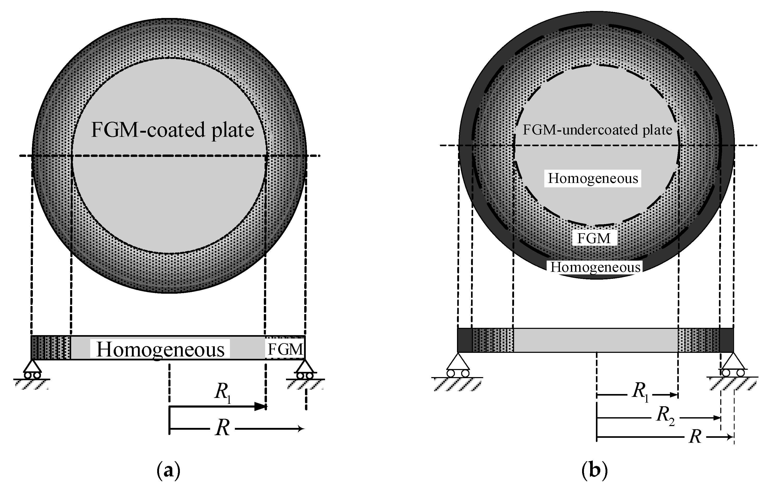
3. Circular Plate Coated with Radially FGM
3.1. The Homogeneous Portion of the FGM-Coated Circular Plate:
3.2. The FGM Annular Portion of the FGM-Coated Circular Plate:
3.3. The Analytical Solution of the FGM-Coated Circular Plate
- (1)
- For
- (2)
- For
- (3)
- For or
3.4. Numerical Solution
4. Circular Plate Undercoated with Radially FGM
4.1. The Homogeneous Circular Portion:
4.2. The FGM-Undercoated Annular Portion:
4.3. The Homogeneous Annular Portion:
4.4. The Analytical Solution of the FGM-Undercoated Circular Plate
- (1)
- For
- (2)
- For
- (3)
- For or
4.5. Numerical Solution
5. Conclusions
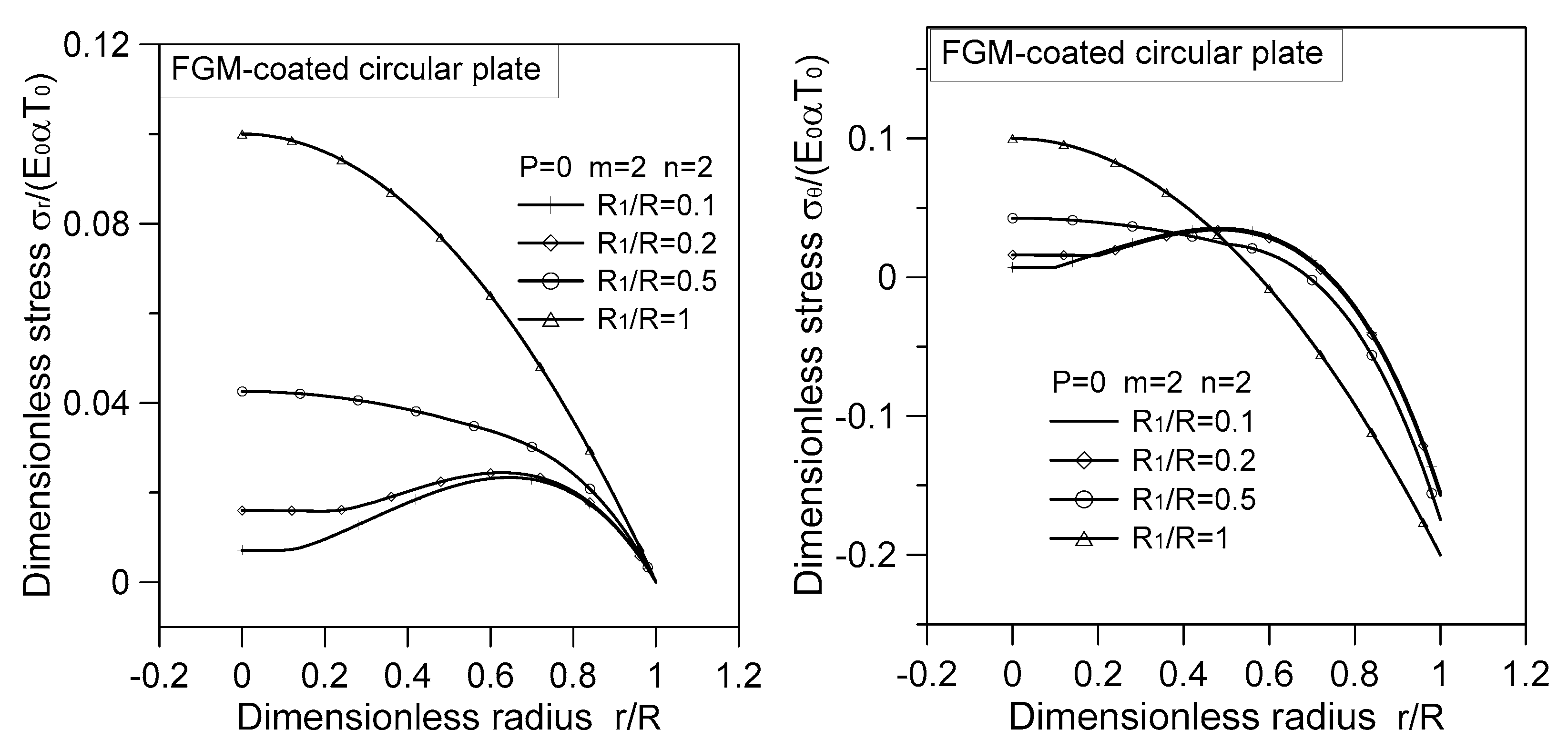
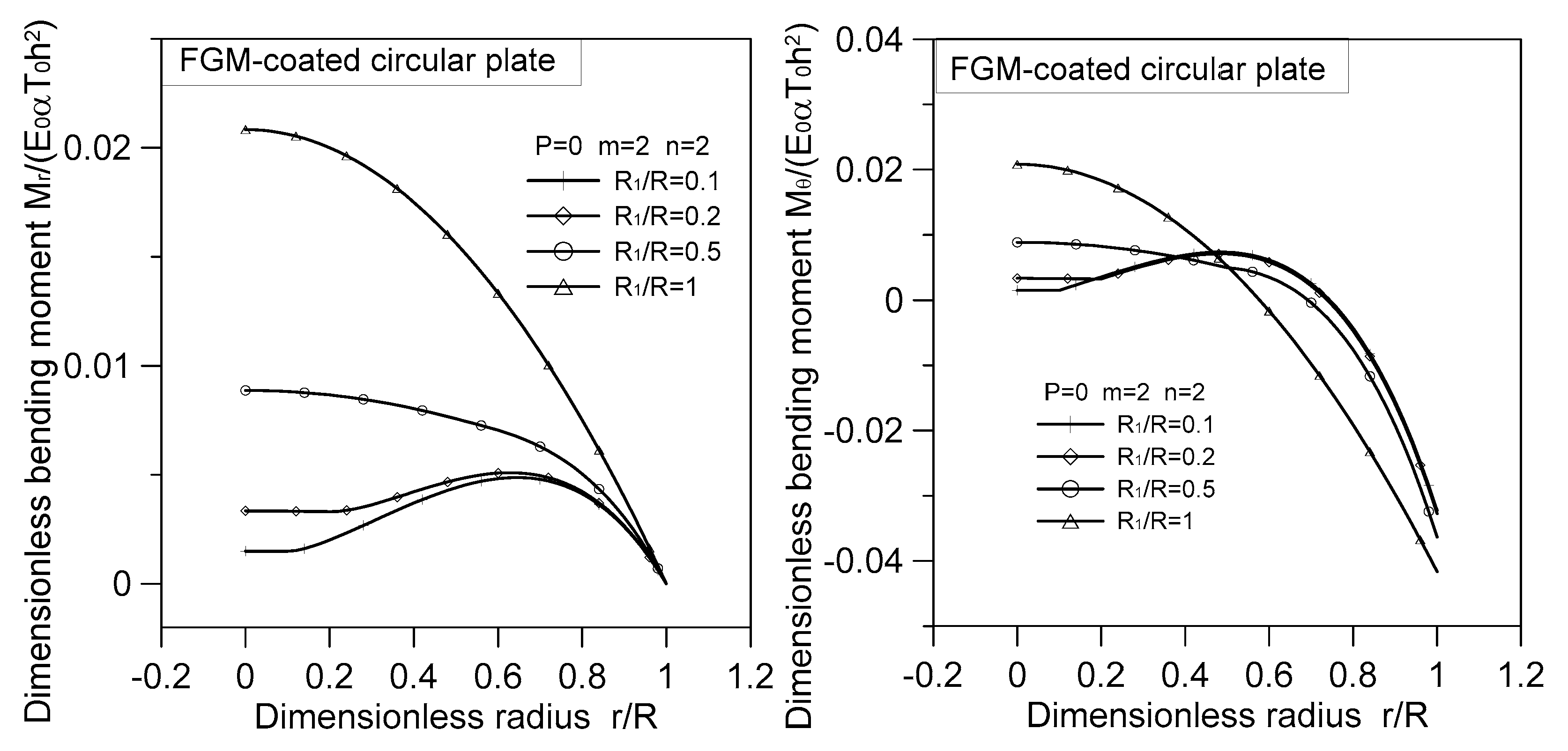
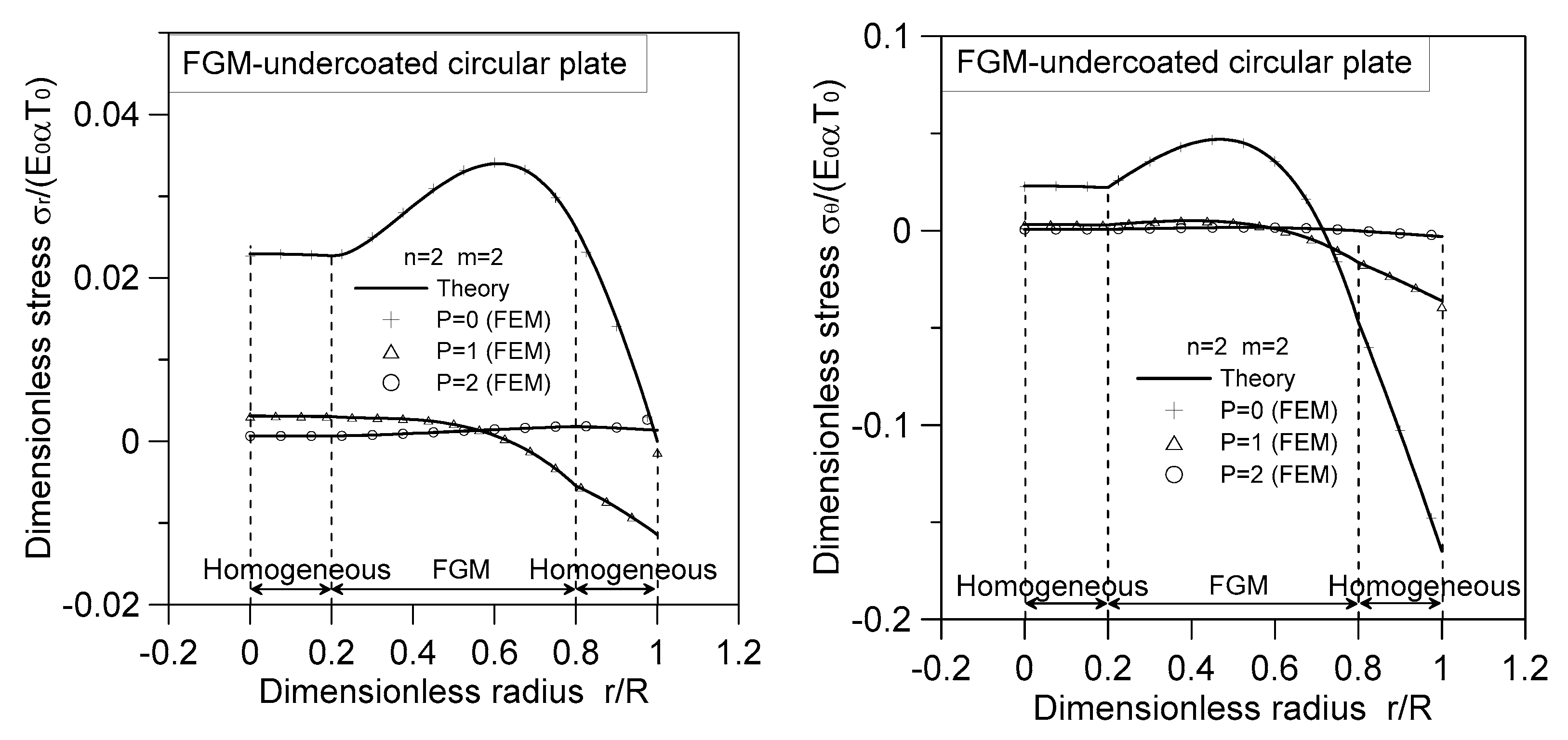
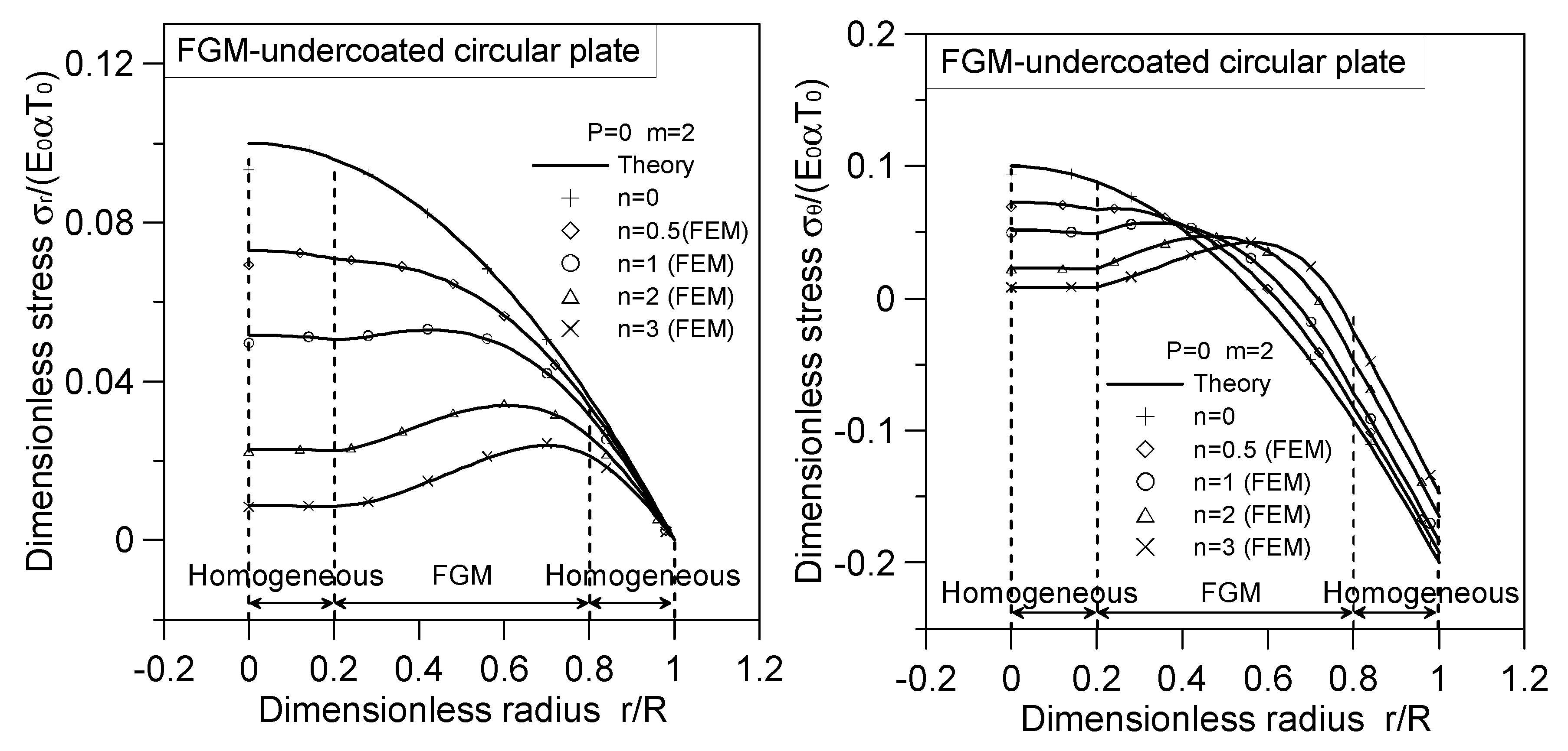
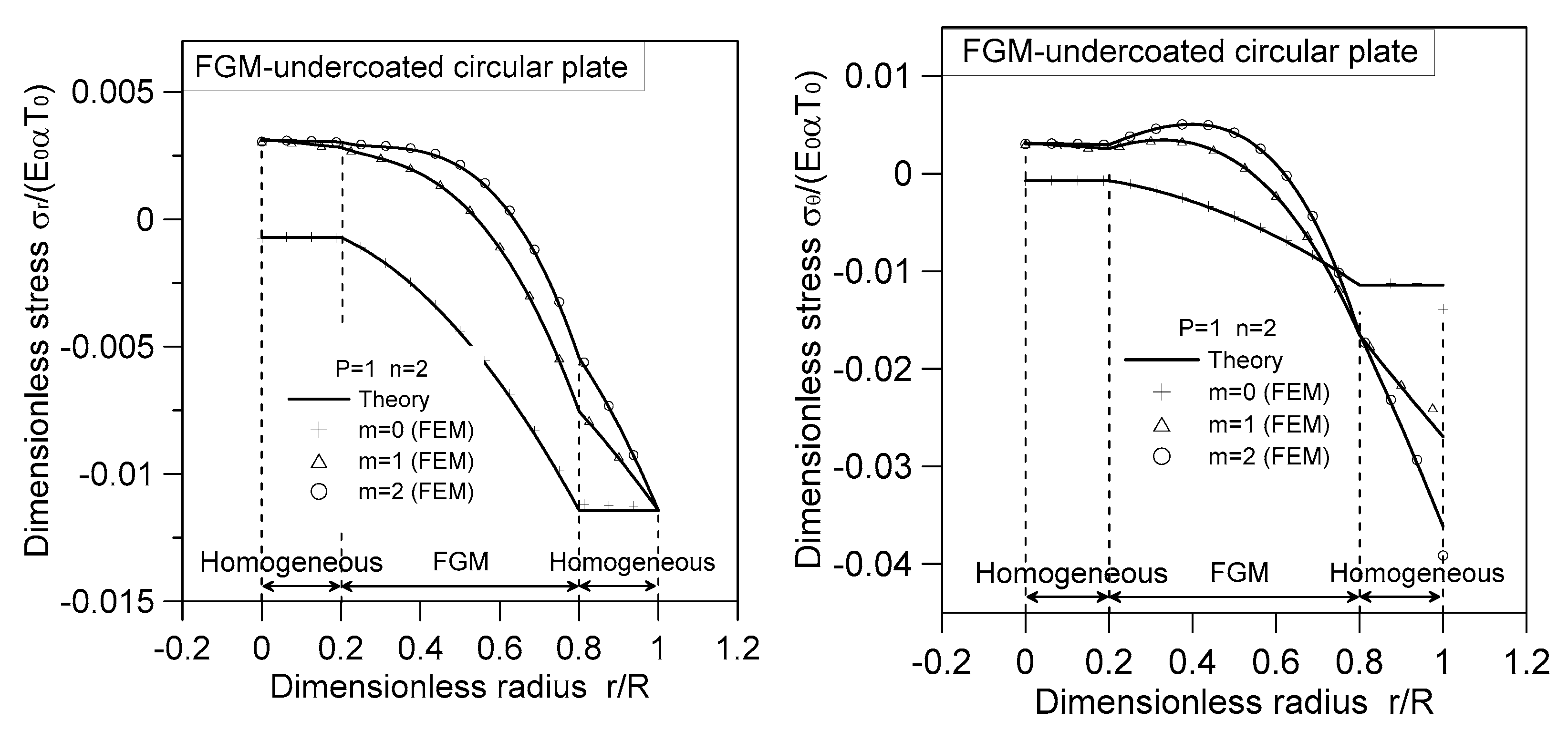
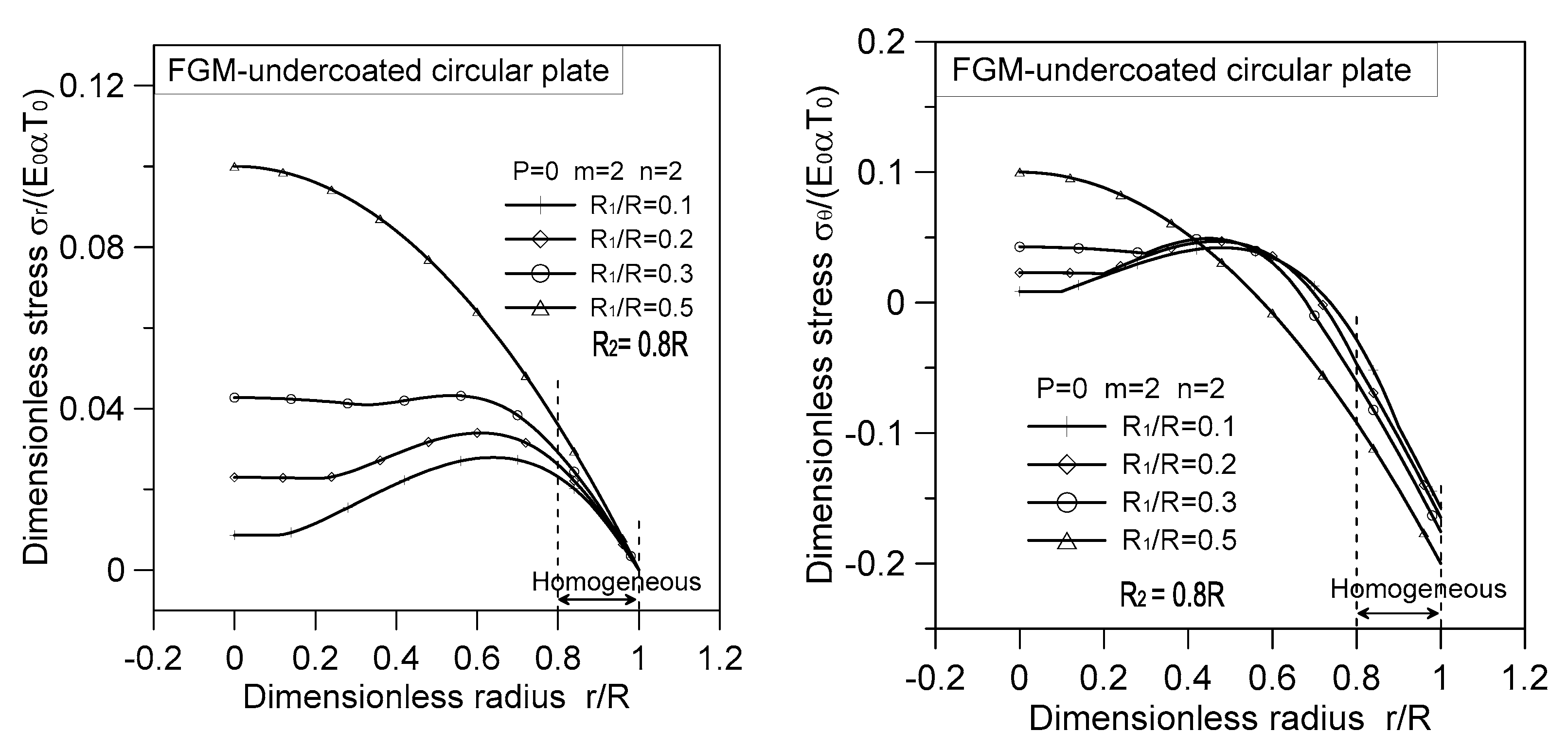
- Incorporating FGM as a coated or undercoated layer can effectively reduce the maximum thermal stress experienced by the circular plate. Notably, the maximum thermal stress in the FGM-coated or FGM-undercoated plate is located within the radius of the circular plate (), which differs from the behavior observed in homogeneous circular plates.
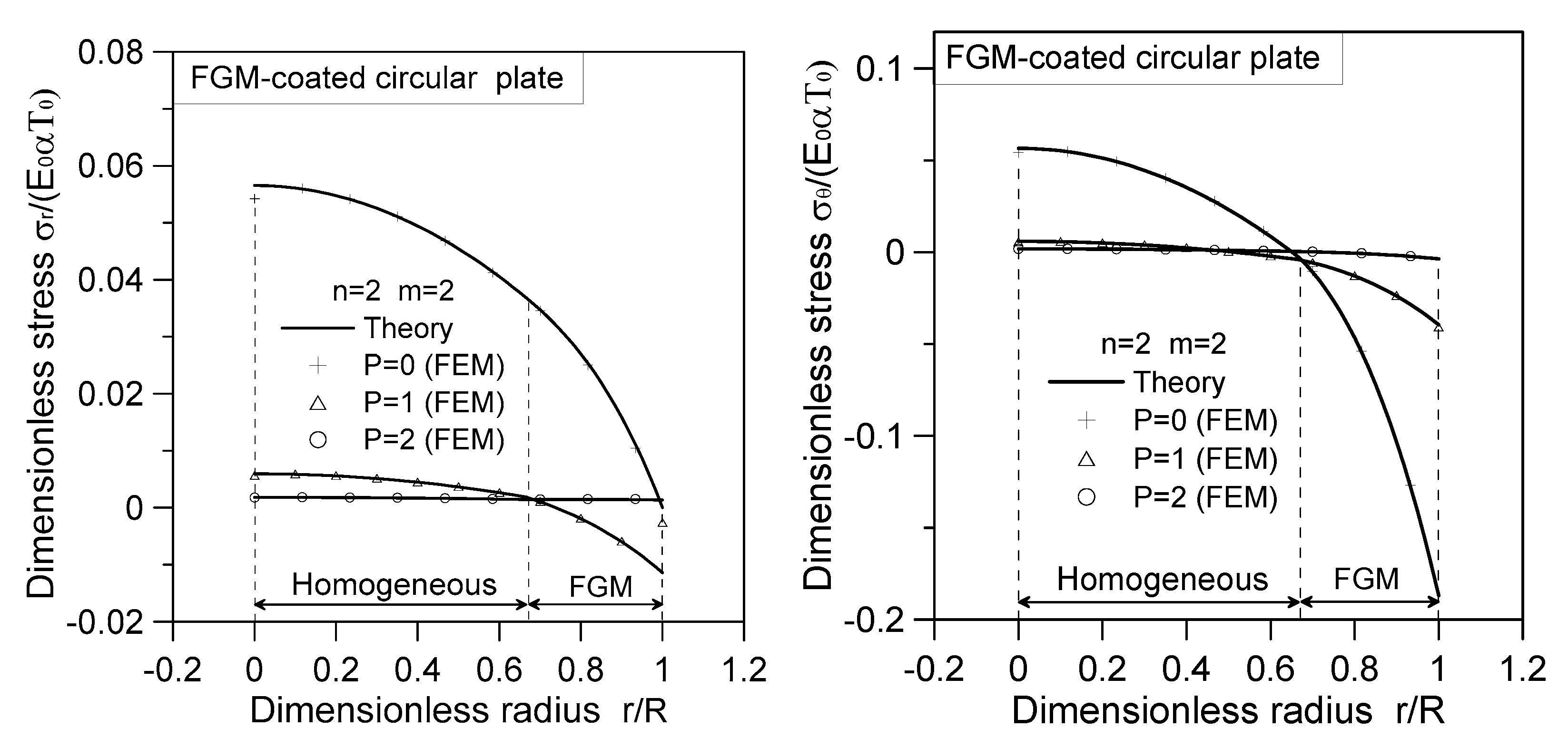
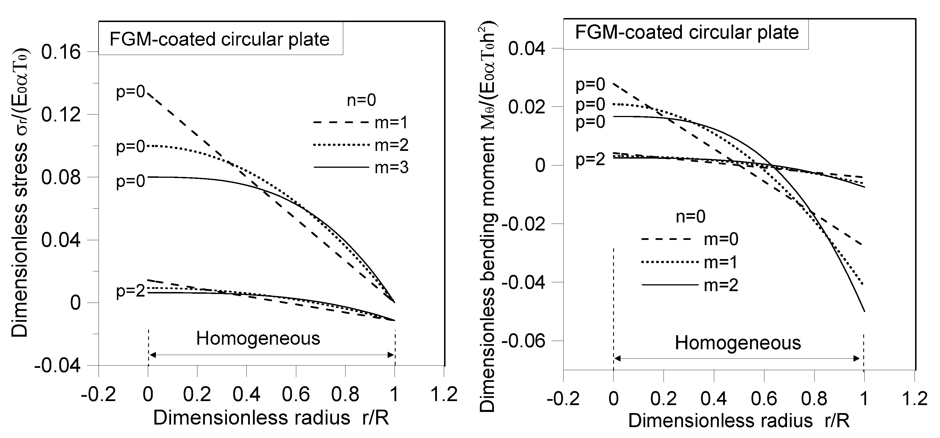
- For the case where the index , the thermal stresses and moments of the FGM-coated circular plate under the thermal load demonstrate the proportional relations of .
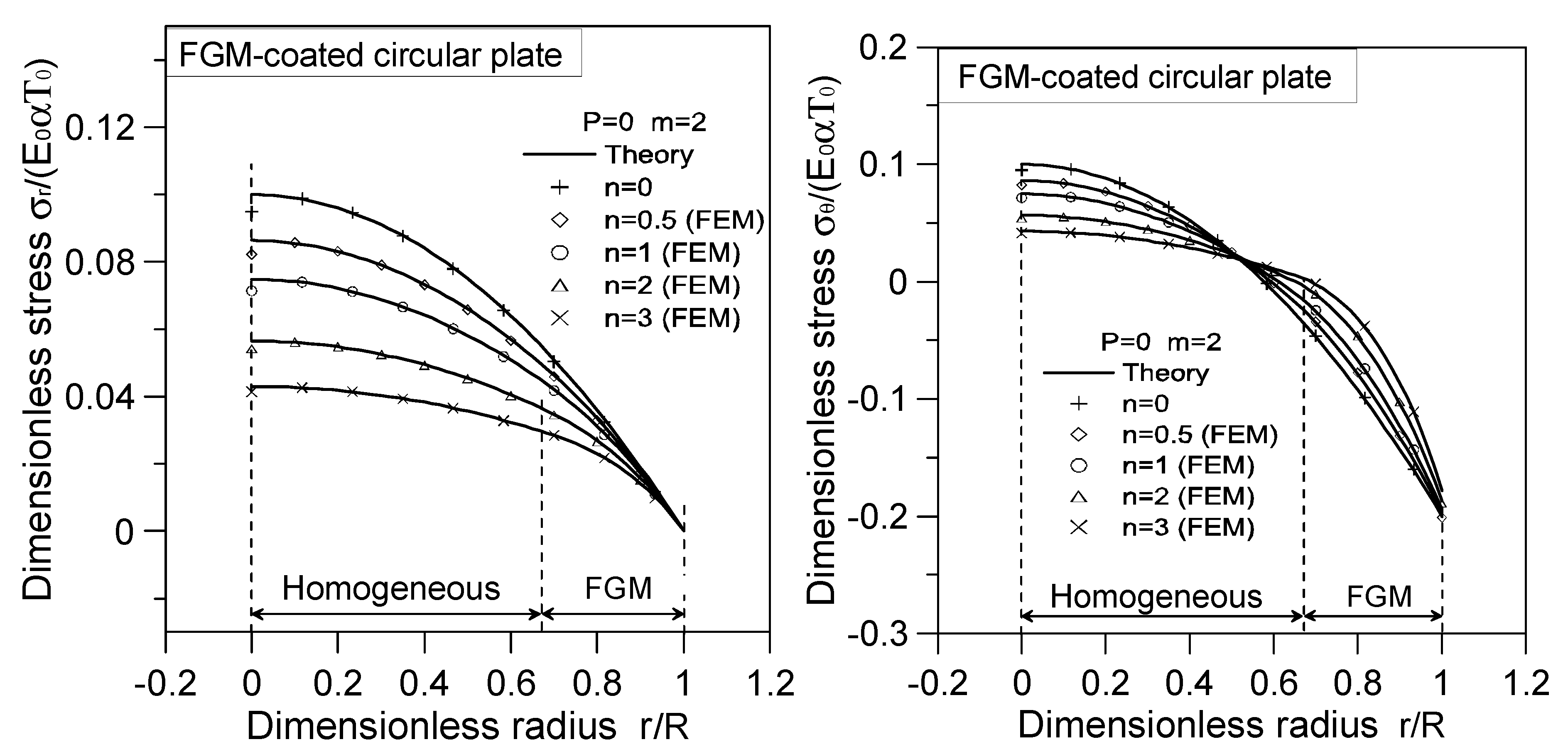
- Under transversely thermal loads (), the stresses at the homogeneous portion of the FGM-coated circular plate remain unaffected by the radius . However, the stresses at the FGM-ring portion vary depending on the radius, owing to the radially varying material properties of the FGM layer.
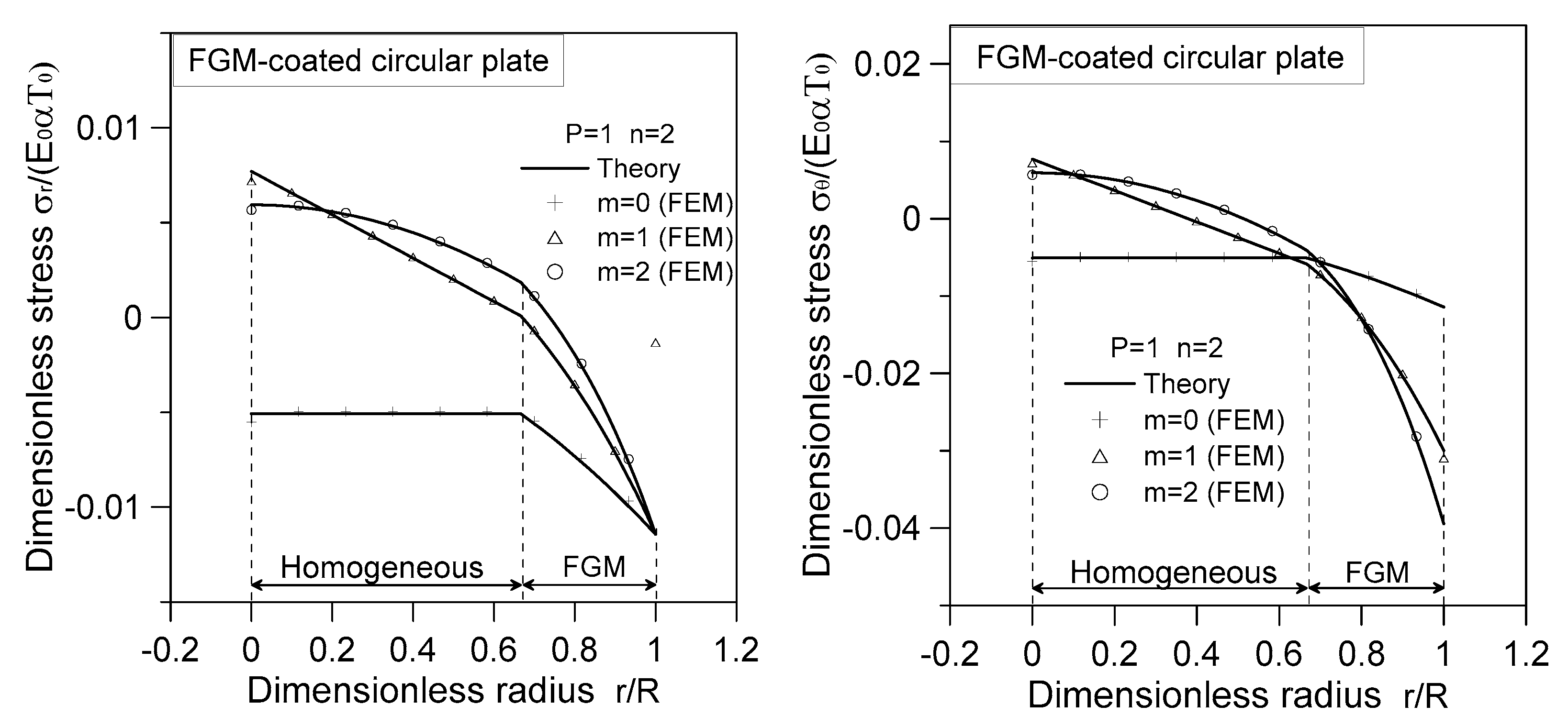
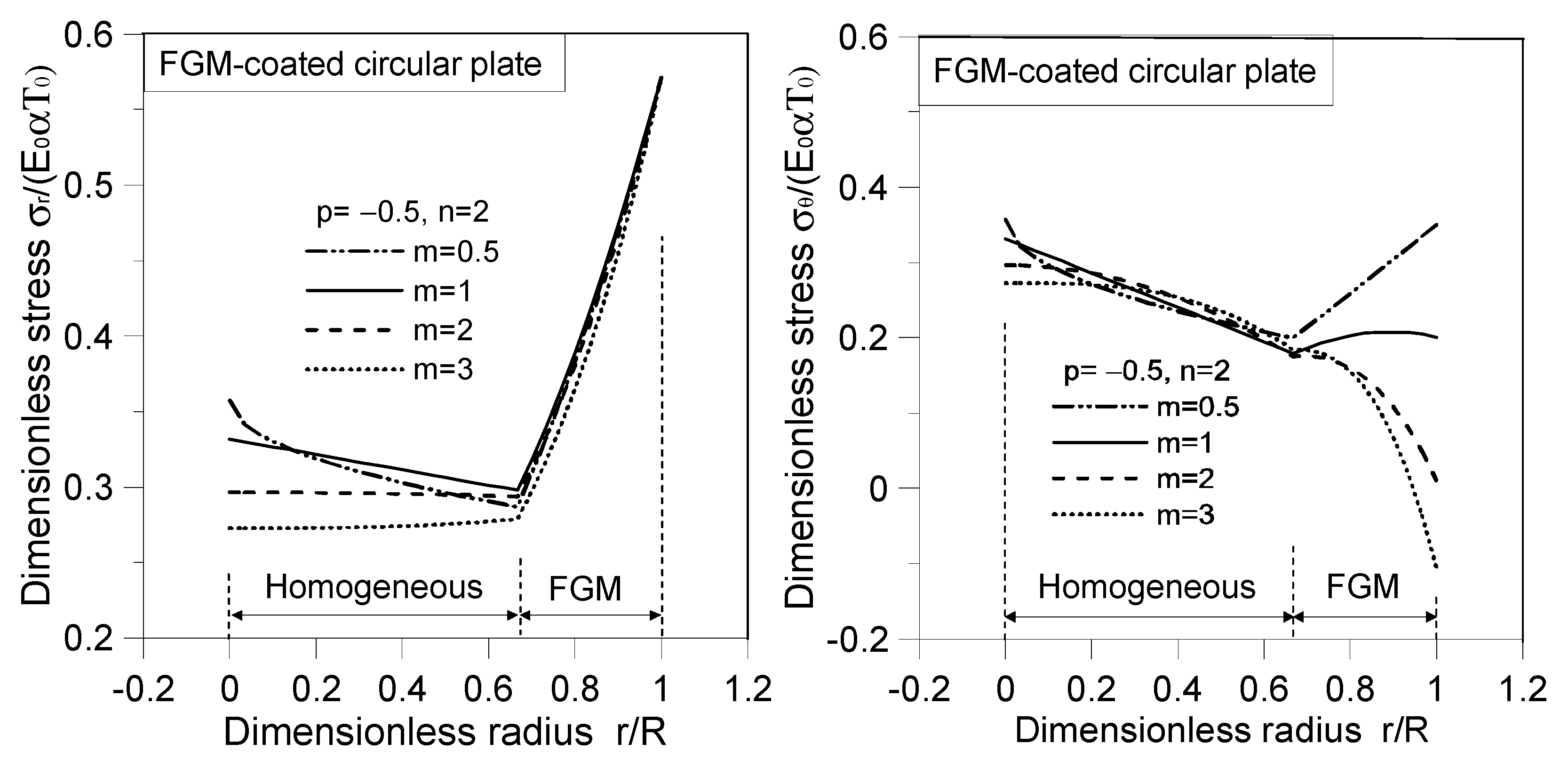
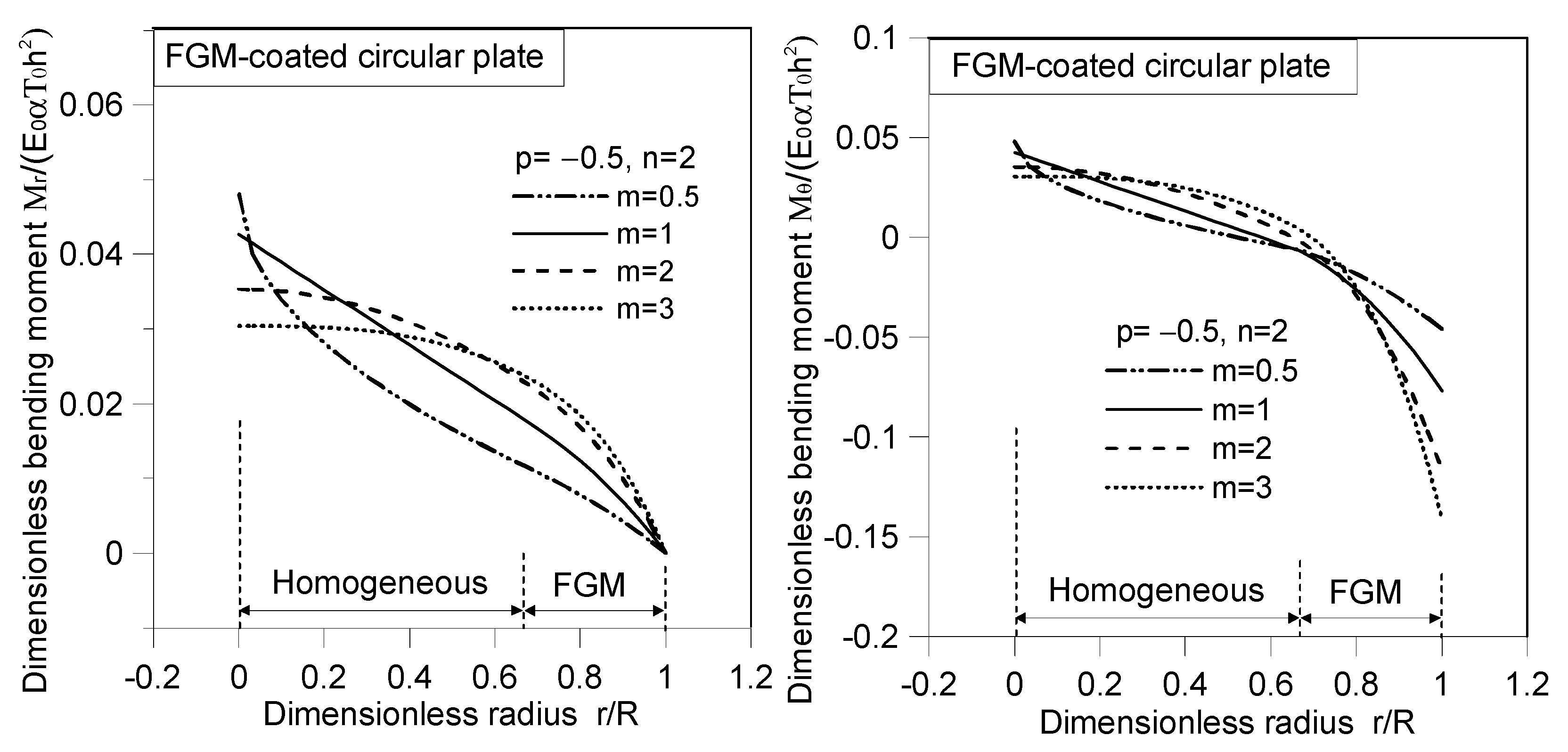
- When subjected to radially thermal loads only (), the stresses and moments of the homogeneous portion depend on the product of influenced by the radially thermal load. Conversely, the stresses and moments of the FGM layer are determined by the function , which takes into account both the thermal load and material gradation.
- The stresses and of the radially FGM-coated circular plate, whether subjected to transversely thermal load only () or radially thermal load only (), exhibit continuity with noticeable inflection points in slope at the interfaces.
- The numerical findings obtained from this study can serve as a benchmark for researchers in validating their numerical methods and results when analyzing similar problems involving FGM-coated and FGM-undercoated circular plates.
- The developed analytical solutions can be applied to analyze the mechanical behavior of various FGM-coated and FGM-undercoated circular plates subjected to different thermal loading conditions. Further investigations can explore their application in specific engineering problems.
Author Contributions
Funding
Institutional Review Board Statement
Informed Consent Statement
Data Availability Statement
Conflicts of Interest
References
- Chung, Y.L.; Chi, S.H. The Residual Stresses of Functionally Graded Materials. J. Chin. Inst. Civ. Hydraul. Eng. 2001, 13, 1–9. [Google Scholar]
- Chung, Y.L.; Chang, H.X. Mechanical behavior of rectangular plates with functionally graded coefficient of thermal expansion subjected to thermal loading. J. Therm. Stress. 2008, 31, 368–388. [Google Scholar] [CrossRef]
- Chung, Y.L. Thermoelastic closed-form solutions of FGM plates subjected to temperature change in longitudinal and thickness directions. Meccanica 2022, 57, 355–369. [Google Scholar] [CrossRef]
- Golmakani, M.E.; Kadkhodayan, M. Large deflection analysis of circular and annular FGM plates under thermo-mechanical loadings with temperature-dependent properties. Compos. Part B Eng. 2011, 42, 614–625. [Google Scholar] [CrossRef]
- Dai, H.L.; Yan, X.; Yang, L. Thermoelastic Transient Behavior for a Clamped FGM Circular Plate. Int. J. Struct. Stab. Dyn. 2014, 14, 1450005. [Google Scholar] [CrossRef]
- Parandvar, H.; Farid, M. Nonlinear reduced order modeling of functionally graded plates subjected to random load in thermal environment. Compos. Struct. 2015, 126, 174–183. [Google Scholar] [CrossRef]
- Alibeigloo, A. Thermo elasticity solution of sandwich circular plate with functionally graded core using generalized differential quadrature method. Compos. Struct. 2016, 136, 229–240. [Google Scholar] [CrossRef]
- Ding, S.; Wu, C.P. Optimization of material composition to minimize the thermal stresses induced in FGM plates with temperature-dependent material properties. Int. J. Mech. Mater. Des. 2018, 14, 527–549. [Google Scholar] [CrossRef]
- Zhang, J.H.; Pan, S.C.; Chen, L.K. Dynamic thermal buckling and postbuckling of clamped-clamped imperfect functionally graded annular plates. Nonlinear Dyn. 2019, 95, 565–577. [Google Scholar] [CrossRef]
- Zarga, D.; Tounsi, A.; Bousahla, A.A.; Bourada, F.; Mahmoud, S.R. Thermomechanical bending study for functionally graded sandwich plates using a simple quasi-3D shear deformation theory. Steel Compos. Struct. 2019, 32, 389–410. [Google Scholar] [CrossRef]
- Vaghefi, R. Thermo-elastoplastic analysis of functionally graded sandwich plates using a three-dimensional meshless model. Compos. Struct. 2020, 242, 112144. [Google Scholar] [CrossRef]
- Moleiro, F.; Madeira, J.F.A.; Carrera, E.; Reddy, J.N. Design optimization of functionally graded plates under thermo-mechanical loadings to minimize stress, deformation and mass. Compos. Struct. 2020, 245, 112360. [Google Scholar] [CrossRef]
- Bagheri, H.; Kiani, Y.; Eslami, M.R. Asymmetric thermal buckling of temperature dependent annular FGM plates on a partial elastic foundation. Comput. Math. Appl. 2018, 75, 1566–1581. [Google Scholar] [CrossRef]
- Ghiasian, S.E.; Kiani, Y.; Sadighi, M.; Eslami, M.R. Thermal buckling of shear deformable temperature dependent circular/annular FGM plates. Int. J. Mech. Sci. 2014, 81, 137–148. [Google Scholar] [CrossRef]
- Kiani, Y. Axisymmetric static and dynamics snap-through phenomena in a thermally postbuckled temperature-dependent FGM circular plate. Int. J. Non-Linear Mech. 2017, 89, 1–13. [Google Scholar] [CrossRef]
- Akgöz, B.; Civalek, Ö. Effects of thermal and shear deformation on vibration response of functionally graded thick composite microbeams. Compos. Part B Eng. 2017, 129, 77–87. [Google Scholar] [CrossRef]
- Javani, M.; Kiani, Y.; Eslami, M.R. Large amplitude thermally induced vibrations of temperature dependent annular FGM plates. Compos. Part B Eng. 2019, 163, 371–383. [Google Scholar] [CrossRef]
- Chung, Y.L.; Chen, W.T. Bending behavior of FGM-coated and FGM-undercoated plates with two simply supported opposite edges and two free edges. Compos. Struct. 2007, 81, 157–167. [Google Scholar] [CrossRef]
- Chi, S.H.; Chung, Y.L. Cracking in coating-substrate composites with multi-layered and FGM coatings. Eng. Fract. Mech. 2003, 70, 1227–1243. [Google Scholar] [CrossRef]
- Han, Q.F.; Wang, Z.W.; Nash, D.H.; Liu, P.Q. Thermal buckling analysis of cylindrical shell with functionally graded material coating. Compos. Struct. 2017, 181, 171–182. [Google Scholar] [CrossRef]
- Mao, J.J.; Ke, L.L.; Yang, J.; Kitipornchai, S.; Wang, Y.S. The coupled thermoelastic instability of FGM coatings with arbitrarily varying properties: In-plane sliding. Acta Mech. 2018, 229, 2979–2995. [Google Scholar] [CrossRef]
- Daikh, A.A.; Megueni, A. Thermal buckling analysis of functionally graded sandwich plates. J. Therm. Stress. 2018, 41, 139–159. [Google Scholar] [CrossRef]
- Dung, D.V.; Nga, N.T. Thermomechanical postbuckling analysis of eccentrically stiffened FGM sandwich plates with general Sigmoid and power laws based on TSDT. J. Sandw. Struct. Mater. 2018, 20, 907–945. [Google Scholar] [CrossRef]
- Daikh, A.A.; Drai, A.; Bensaid, I.; Houari, M.S.A.; Tounsi, A. On vibration of functionally graded sandwich nanoplates in the thermal environment. J. Sandw. Struct. Mater. 2021, 23, 2217–2244. [Google Scholar] [CrossRef]
- Nguyen, V.C.; Tran, H.Q.; Pham, V.V. Nonlinear static analysis of bi-directional functionally graded sandwich plates in thermal environments by a higher-order finite element model. Thin-Walled Struct. 2023, 188, 110819. [Google Scholar] [CrossRef]
- Sah, S.K.; Ghosh, A. Influence of porosity distribution on free vibration and buckling analysis of multi-directional functionally graded sandwich plates. Compos. Struct. 2022, 279, 114795. [Google Scholar] [CrossRef]
- Najafizadeh, M.M.; Heydari, H.R. An exact solution for buckling of functionally graded circular plates based on higher order shear deformation plate theory under uniform radial compression. Int. J. Mech. Sci. 2008, 50, 603–612. [Google Scholar] [CrossRef]
- Wan, Z.Q.; Li, S.R.; Li, Q.Q. Homogenized and classical expressions for bending solutions of functionally graded levinson circular plates. Gongcheng Lixue/Eng. Mech. 2015, 32, 10–16. [Google Scholar] [CrossRef]
- Dai, H.L.; Dai, T.; Cheng, S.K. Transient Response Analysis for a Circular Sandwich Plate with an FGM Central Disk. J. Mech. 2015, 31, 417–426. [Google Scholar] [CrossRef]
- Chung, Y.L.; Ou, Z.X. Exact bending solutions of circular sandwich plates with functionally graded material-undercoated layer subjected to axisymmetric distributed loads. J. Sandw. Struct. Mater. 2020, 23, 2856–2881. [Google Scholar] [CrossRef]
- Nie, G.; Zhong, Z. Axisymmetric bending of two-directional functionally graded circular and annular plates. Acta Mech. Solida Sin. 2007, 20, 289–295. [Google Scholar] [CrossRef]
- Sburlati, R. Stress concentration factor due to a functionally graded ring around a hole in an isotropic plate. Int. J. Solids Struct. 2013, 50, 3649–3658. [Google Scholar] [CrossRef]
- Goyat, V.; Verma, S.; Garg, R.K. On the reduction of stress concentration factor in an infinite panel using different radial functionally graded materials. Int. J. Mater. Prod. Technol. 2018, 57, 109–131. [Google Scholar] [CrossRef]
- Hetnarski, R.B. Thermal Stress I; Achenbach, J.D., Ed.; North-Holland: New York, NY, USA, 1986. [Google Scholar]


| r/R | |||||||||
|---|---|---|---|---|---|---|---|---|---|
| FEM | Analytical | Error (%) | FEM | Analytical | Error (%) | FEM | Analytical | Error (%) | |
| 0 | 0.0542001 | 0.056543 | 4.144 | 0.005665 | 0.005942 | 4.649 | 0.001792 | 0.001816 | 1.346 |
| 0.1 | 0.0561685 | 0.056099 | 0.125 | 0.005931 | 0.00585 | 1.366 | 0.001845 | 0.001807 | 2.093 |
| 0.2 | 0.0547974 | 0.054765 | 0.058 | 0.005651 | 0.005574 | 1.383 | 0.001819 | 0.00178 | 2.121 |
| 0.3 | 0.0525399 | 0.052543 | 0.006 | 0.005188 | 0.005113 | 1.464 | 0.001775 | 0.001736 | 2.211 |
| 0.4 | 0.0493821 | 0.049432 | 0.100 | 0.004541 | 0.004469 | 1.613 | 0.001714 | 0.001673 | 2.347 |
| 0.5 | 0.0453222 | 0.045432 | 0.242 | 0.003709 | 0.00364 | 1.884 | 0.001635 | 0.001593 | 2.538 |
| 0.6 | 0.0403602 | 0.040543 | 0.451 | 0.002691 | 0.002627 | 2.433 | 0.001538 | 0.001496 | 2.788 |
| 0.7 | 0.0345711 | 0.034722 | 0.434 | 0.001124 | 0.001036 | 8.500 | 0.001478 | 0.001425 | 3.610 |
| 0.8 | 0.0266747 | 0.026978 | 1.124 | −0.00184 | −0.00195 | 5.657 | 0.001507 | 0.001434 | 4.864 |
| 0.9 | 0.0152738 | 0.015857 | 3.679 | −0.00587 | −0.00600 | 2.081 | 0.001515 | 0.001418 | 6.377 |
| 1 | 0.000000 | 0.000000 | 0.000 | −0.01256 | −0.01143 | 9.891 | 0.001446 | 0.001355 | 6.289 |
Disclaimer/Publisher’s Note: The statements, opinions and data contained in all publications are solely those of the individual author(s) and contributor(s) and not of MDPI and/or the editor(s). MDPI and/or the editor(s) disclaim responsibility for any injury to people or property resulting from any ideas, methods, instructions or products referred to in the content. |
© 2023 by the authors. Licensee MDPI, Basel, Switzerland. This article is an open access article distributed under the terms and conditions of the Creative Commons Attribution (CC BY) license (https://creativecommons.org/licenses/by/4.0/).
Share and Cite
Chung, Y.-L.; Lin, Z.-H. Analytical Thermal Analysis of Radially Functionally Graded Circular Plates with Coating or Undercoating under Transverse and Radial Temperature Distributions. Appl. Sci. 2023, 13, 7061. https://doi.org/10.3390/app13127061
Chung Y-L, Lin Z-H. Analytical Thermal Analysis of Radially Functionally Graded Circular Plates with Coating or Undercoating under Transverse and Radial Temperature Distributions. Applied Sciences. 2023; 13(12):7061. https://doi.org/10.3390/app13127061
Chicago/Turabian StyleChung, Yen-Ling, and Zong-Han Lin. 2023. "Analytical Thermal Analysis of Radially Functionally Graded Circular Plates with Coating or Undercoating under Transverse and Radial Temperature Distributions" Applied Sciences 13, no. 12: 7061. https://doi.org/10.3390/app13127061
APA StyleChung, Y.-L., & Lin, Z.-H. (2023). Analytical Thermal Analysis of Radially Functionally Graded Circular Plates with Coating or Undercoating under Transverse and Radial Temperature Distributions. Applied Sciences, 13(12), 7061. https://doi.org/10.3390/app13127061