1. Introduction
The FGM structures presented in this work were obtained by mixing two different component materials, in this case, a metal and a ceramic, in such a way that a continuous variation over the thickness direction of the material properties was verified, in contrast with the laminated composite material structures. Metal–ceramic FGM plates and shells are widely used in engineering in aircraft, space vehicles, and other engineering applications.
Depending on the load level, structures can experience material nonlinearity known as elastoplasticity, which should be avoided because of large deformations resulting from elastoplastic behaviour in isotropic and FGM structures.
In recent years, many research studies on FGM structures were done. Here, we focused our attention on axisymmetric-shell-related studies: Reddy et al. [
1], Li et al. [
2], Tran et al. [
3] and Thai et al. [
4] studied circular plates in linear and geometrically nonlinear behaviour using different theories and to provide different analyses: static bending, dynamic and buckling.
Regarding the structural optimization involving FGM plates and shells of revolution, there is a lack of publications specifically devoted to elastoplastic behaviour.
Elastoplasticity analysis has been less investigated in FGM structures. Zhang and Zhou [
5] presented a model for FGM circular plates based on a physical neutral surface and higher-order shear deformation theory. Moita et al. [
6] presented a formulation for linear and nonlinear static bending and elastoplasticity analysis of functionally graded axisymmetric plate/shell-type structures under mechanical loading. Moita et al. [
7] presented structural and sensitivity analyses, allowing for the material distribution and sizing optimization of functionally graded material structures. The finite element model used in this work was the same as the one previously used by the authors in references [
6,
7]. Other studies that dealt with the optimization of FGM of different types of structures and objective functions are as follows: Cho et al. [
8], Chen and Tong. [
9], Xia and Wang [
10], Ashjari and Khoshravan [
11], Wang et al. [
12], Shabana et al. [
13] and Franco et al. [
14]. In what concerns the elastoplastic behaviour of axisymmetric shells, the work of Popov and Sharifi [
15] can be mentioned and was used here for comparison and validation purposes.
In this paper, we present the elastoplastic analysis and subsequent thickness optimization results of functionally graded axisymmetric structures subjected to axisymmetric loading. To avoid the elastoplastic behaviour of the structures, it was necessary to find the minimum thicknesses (which correspond to the minimum mass of the structure) that provide an elastic behaviour for a certain load level. This kind of optimization problem is not encountered in the literature, and therefore, it was the main objective of this work.
The solutions were obtained using a finite element model based on Zienckiewics et al. [
16]. The analyses of some illustrative optimization applications were performed, and the results are presented and discussed.
2. Formulation of the P-FGM Model
The FGM structures considered in the present work were made by mixing two distinct isotropic material phases, in this case, a ceramic and a metal. Using the volume fraction of the constituent materials, as proposed by the power law function in Bao and Wang [
17], the through-thickness material properties of an FGM plate–shell structure can be obtained, as in Moita et al. [
6,
7]. The volume fraction of the ceramic and metal phases for each virtual layer
k is defined according to the power law
where
is the thickness coordinate of the mid-surface of each virtual layer
k.
Knowing the volume fractions
and
and using the rule of mixtures, the material properties, such as Young’s modulus E or mass density ρ, of each virtual layer of an FGM can be determined:
These equations show that when p = 0, the plate is fully ceramic and when p = ∞, the plate is fully metal.
3. Displacement and Stress Fields
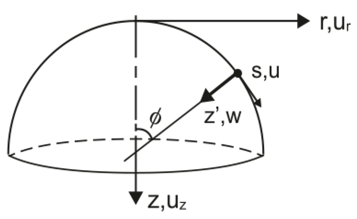
Figure 1 shows an axisymmetric shell that is subjected to axisymmetric loading. Considering Kirchhoff’s theory, the displacement field is given by
where u and
are displacements of a generic point in the middle plane with respect to the local axes.
Imposing a constraint , hence , where is the rotation of the normal to the middle plane, which can vary independently, one can obtain the transverse shear strain.
For the conical frustum finite element with straight elements, as in Zienckiewics et al. [
16], applied to axisymmetric shells under axisymmetric loading, we have
and
0. The linear strain components in the local curvilinear system are given as follows:
The relations between the local (s, z’) and global (r, z) coordinates, as well as the local–global displacements, can be found in Moita et al. [
7], and, after this transformation, the strain–displacement relations written in terms of global displacements are
Equation (3) is then written as
and the stress–strain relations for each virtual layer
k are given by
where
and
are the stress and strain vectors, respectively, and
is the elasticity matrix for a virtual layer
k:
where
and [0] are (2 × 2) sub-matrices and
is the middle surface z coordinate of a generic virtual layer
k.
The constitutive equation for a virtual layer
k is then given by
where
are the resultant forces and moments and
is the constitutive matrix.
The functionally graded materials have nonsymmetric properties through the thickness, and for this reason, the bending–stretching coupling exists, and thus, Equation (9) takes the form given in Moita et al. [
6]:
4. Elastoplastic Formulation for FGM Structures
As described in Moita et al. [
6], the present study used an extended Tamura–Tomota–Ozawa (TTO) model to describe the elastic–plastic behaviour of ceramic/metal FGM. This extended TTO model uses the stress–strain transfer parameter
, which depends on the constituent material properties and the microstructural interaction in the FG material, and is given by Jin et al. [
18]:
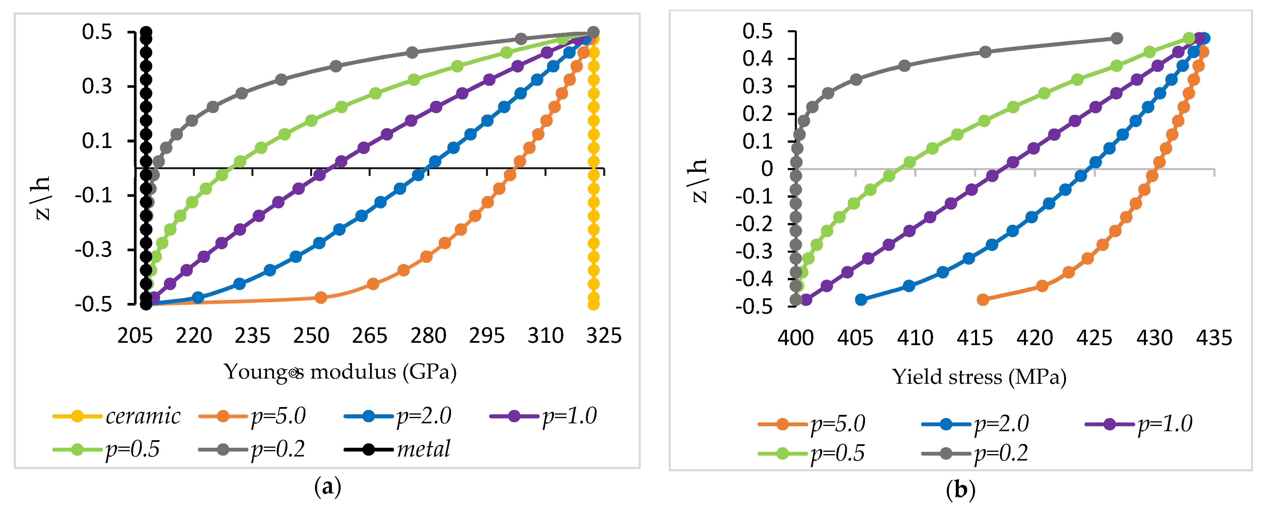
Using this parameter, the through-thickness variation in Young’s modulus and the yield stress
may be obtained as follows:
With these equations, the variations in Young´s modulus and the yield stress for the case of constituents Si
3N
4 and SUS304 are shown in
Figure 2a,b, respectively.
4.1. Elastoplastic Constitutive Relation
To conduct the elastoplastic analysis, the material was assumed to obey the von Mises yielding criterion, and the corresponding yield surface was assumed. The yield condition can be expressed as given in Nayak and Zienkiewicz [
19]:
where the yield level
can be a function of the hardening parameter
.
For the case of the virtual layer approach, for each layer of an FGM structure, and considering the present type of shell and type of loading, the effective stress f (σ,
) is given by
Furthermore, the effect of the shear stress can be neglected. In this case, we have
Thus, the yield surface for each virtual layer
k is given by
where
f () =
and
are the effective stress and the constant uniaxial yield stress of a virtual layer, respectively. It should be emphasized that for the FGM, the mechanical properties vary through the thickness because of the changes in
(or
through the thickness.
The previous equations were then modified by separating the membrane and bending stresses to consider the simplest yield condition proposed by Ilyushin [
20]:
4.2. Flow Rule
Following the development of Nayak and Zienckiewics [
19], the plastic strain increment is defined as being proportional to the stress gradient of a plastic potential
Q, which is taken to be equal to the yield surface condition for an associated flow rule. At the beginning of plasticity, the total increment of strains in elastoplasticity can be calculated by summing up the elastic and the plastic strain components:
Introducing the flow vector
, the following can be written:
For elastic behaviour given in Equation (8), the incremental constitutive elastoplastic relation is then given by
and the elastoplastic constitutive matrix is given by
where the hardening parameter
can be obtained from uniaxial testing.
In this study, ideal plasticity (i.e., with no hardening) was considered, leading to A = 0. To satisfy the yield criterion, the state of stress cannot move outside the yield surface. Following the procedure of Owen and Hinton [
21], this discrepancy can be practically eliminated by ensuring that after the beginning of elastoplasticity, the load increments considered in the solution are sufficiently small. Moreover, the state of stress can be reduced to the yield surface by scaling the strain vector.
5. Finite Element Approach
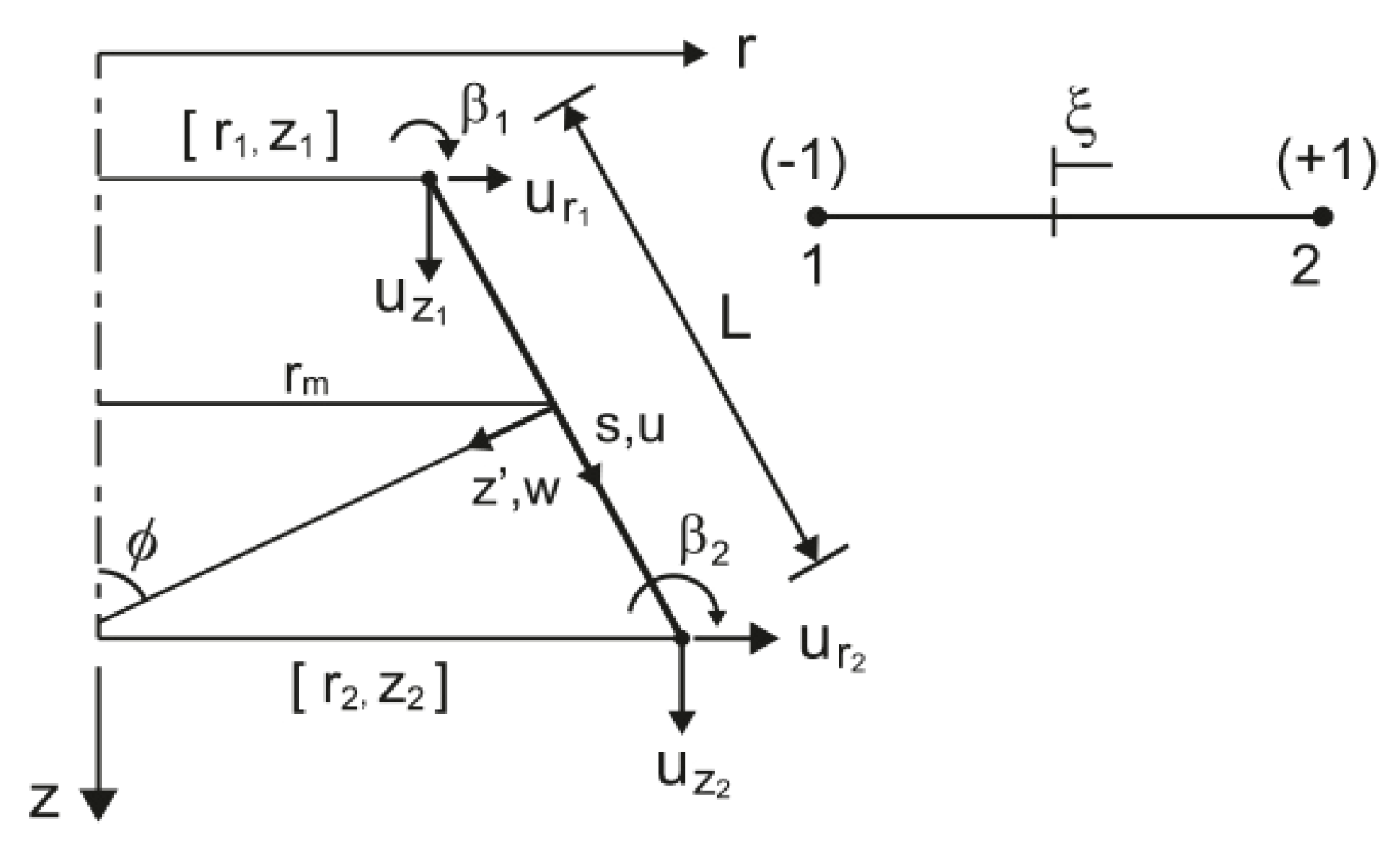
As mentioned before, for a conical frustum, which is a straight finite element, as shown in
Figure 3, with two nodes and three degrees of freedom per node, the displacements and rotation u
ri, u
ri and
were used in this work.
The simplest interpolations were given by Zienkiewics et al. [
8]:
, with
and
. Thus,
and
. For numerical integration, reduced integration with one Gauss point was used at the coordinate
, leading to accurate results for thin and thick structures, as validated elsewhere. From previous expressions,
,
,
and
.
The displacement field can be represented in matrix form as
where
ae is the element displacement vector,
is the displacement vector of node i and
are the shape functions. Thus, we have
From this displacement field, the linear strains are as given as follows:
where ϕ is the angle represented in
Figure 3.
Elastoplastic Analysis
The virtual work principle applied to elastoplasticity analysis is given by
Integrating through the thickness, Equation (26) can be written in the following form:
where
Considering all elements in the domain, a system of equilibrium equations is obtained, and by using the Newton–Raphson incremental/iterative (I;i) method, the incremental equilibrium path can be obtained as follows:
At any increment iteration
i, we have
At the end of each increment
I,
and the residual force vector is very small, i.e.,
where
is a predefined tolerance.
6. Optimization
In the present work, the objective of the optimization problem was to find the design variable h (shell thickness) that minimized an objective function Ω (mass of the structure), subjected to a set of constraints (here, the material yield stresses) for a specific applied load level and a specific gradient index
p:
subjected to
p = constant and the mass of the structure calculated using
For each virtual layer k, we have at any optimization iteration, where VL = 20 is the number of virtual layers used in this work. More details justifying the use of this value can be found in previous works from the first author.
The sensitivities of the objective function and constraint functions can be evaluated analytically, as was done in the work of Moita et al. [
7], or evaluated by using global finite differences. The optimization problem was solved by using a gradient-based algorithm, namely, the feasible arc interior point algorithm developed by Herskovits [
22] and Herskovits et al. [
23]. In this work, the sensitivities were obtained mainly using the global finite difference method, except otherwise stated.
7. Applications
From the work of Moita et al. [
6], where the analysis of elastoplasticity of shells of revolution was previously performed, it was observed that the results obtained using the present model when compared with results from other sources were in excellent agreement and, therefore, we assumed that the validation of the finite element model was previously done. Nevertheless, the accuracy comparison is presented here first for linear analysis in
Section 7.1 and later for elastoplasticity in
Section 7.4. The remaining subsections show several optimization problems conducted for some illustrative cases, which can be used for benchmarking purposes.
7.1. Linear Analysis of a Clamped Circular FGM Plate under a Uniform Pressure Load
The accuracy of the present finite element model (PM) is illustrated in this numerical application. An FGM clamped circular plate, with thickness h and radius R and made of titanium/zirconium was studied (
= 110.25 GPa,
= 0.288, Ec = 278.41 GPa,
= 0.288). Based on the rule of mixtures, the effective modulus was estimated following Reddy et al. [
1]:
with
;
.
Table 1 shows the normalized maximum deflections (at the centre of the plate) when the plate was subjected to a uniform pressure
q, calculated by
,
. An excellent agreement was observed between the results obtained with the present model and the results obtained using Mindlin theory (Reddy et al. [
1]), elasticity theory (Li et al. [
2]) and HSDT theory (Tran et al. [
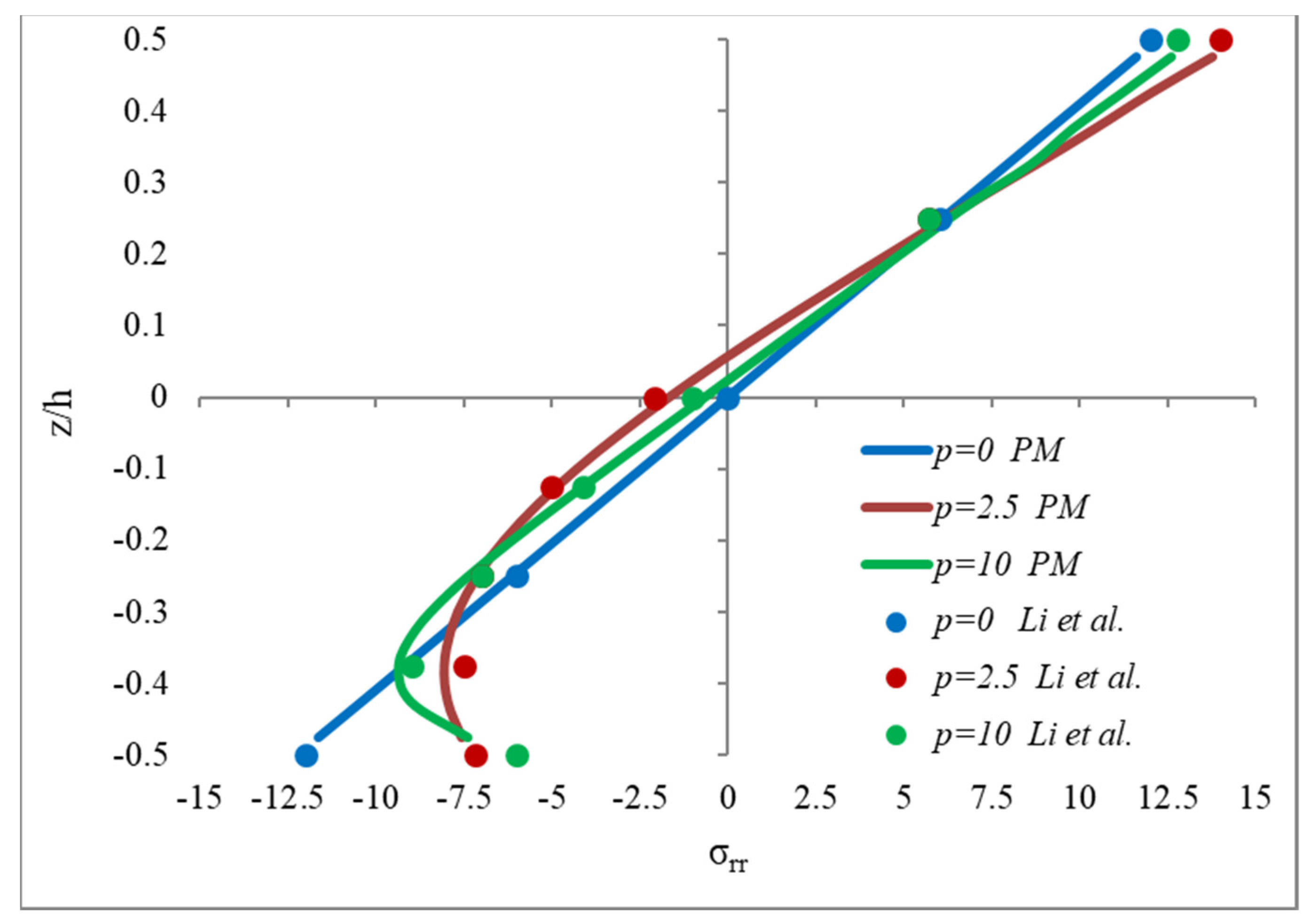
3]). The through-thickness distribution of the nondimensional radial stress is presented in
Figure 4. A comparison with the solution obtained by Li et al. [
2] revealed very good agreement.
7.2. Elastoplastic Optimization of a Circular FGM Plate under a Uniform Pressure Load
A clamped P-FGM circular plate with a radius-to-thickness ratio R/h = 40 was considered, and its geometry was modelled using 10 finite elements. The constituents of the FGM were Si3N4 as the ceramic and SUS304 as the metal, with the following material properties: = 322.27 GPa, = 207.79 GPa, = 0.24, = 0.318, ρc = 2370 kg/m3 and ρm = 8160 kg/m3. The yield stress for SUS304 was considered to be = 400 MPa. The radius of the circular plate was R = 0.5 m, and the initial thickness was h = 12.5 mm. In this numerical example, the gradient index was specified as p = 2.0, and the stress–strain transfer parameter was q* = 60 × 109 Pa. The non-dimensional loads and displacements were given by and wc/h, respectively.
Solving the optimization problem consisted of the minimization of the mass of the plate, subjected to a constraint of the effective stress:
min =
subjected to
. The solution obtained for each different index
p is shown in
Table 2, and
Figure 5 gives the load–displacement paths obtained for the case of
p = 2. Since the final design corresponds to higher thicknesses, this means that the elastic behaviour condition was not met in the initial design.
7.3. Elastoplastic Optimization of a Toroidal Shell under Internal Radial Pressure
A numerical example with an FGM toroidal shell, as represented in
Figure 6, was considered. The toroidal shell was modelled using 24 finite elements in a sequence, starting at the inner point and moving in a clockwise direction (where node 1 was located at the inner point of the circular section of the right side of
Figure 6 such that they were numbered in sequence from 1 to 24 in the clockwise direction). The geometry was defined by r = 254 mm, R = 381 mm and initial thickness h = 12.7 mm corresponding to a mass of m = 335.263 kg. The constituents were zirconia and stainless steel, i.e., ZrO
2/SUS304, with the following properties at 300 K:
= 207.79 GPa,
= 0.3176,
= 168.0 GPa,
= 0.2978,
= 8160 kg/m
3,
= 5700 kg/m
3 and q* = 90 × 10
9 Pa. The inner surface was ceramic and the outer surface was metal. The gradient index
p = 1 was considered, and the shell was subjected to an inner radial pressure load.
Figure 7 shows the original and deformed shapes in which the displacements were enlarged 100 times. In this analysis, a finite element mesh with 48 elements was used.
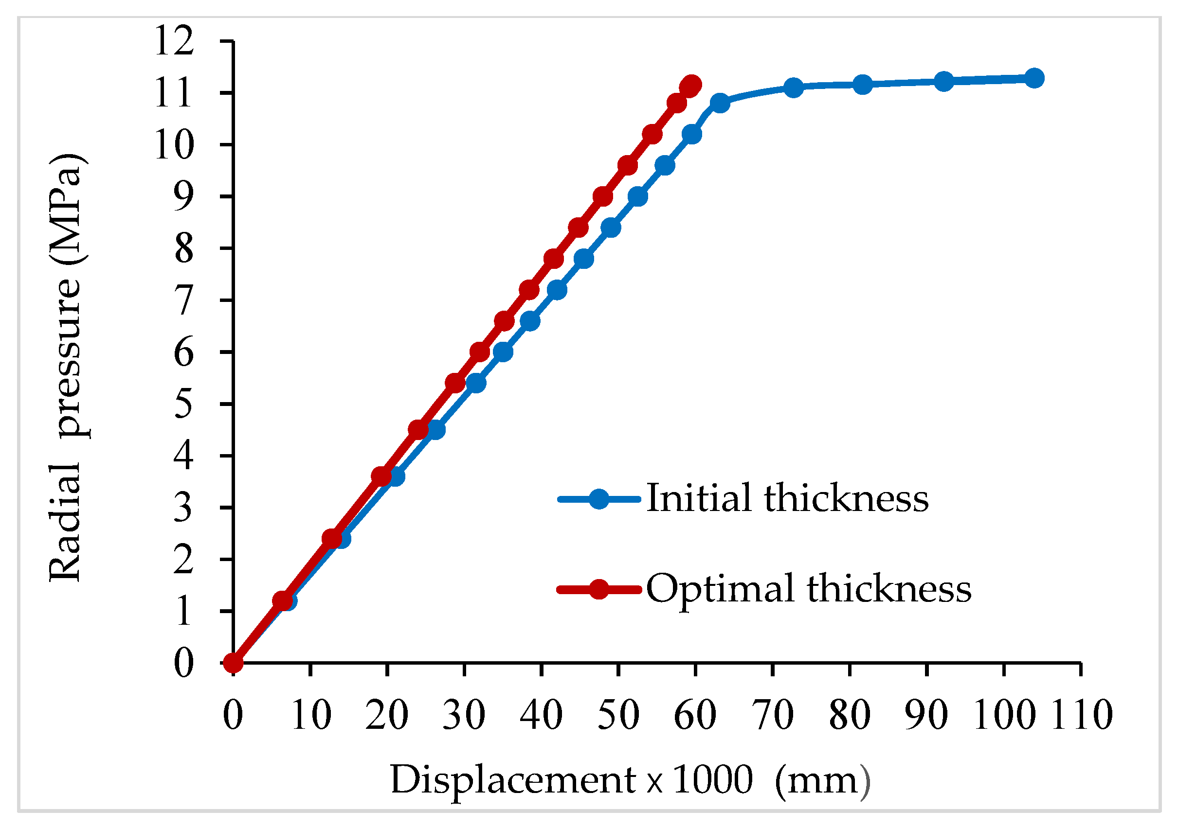
The optimization of the shell was performed with the objective of minimizing the mass of the vessel, with a constraint on the effective stress. It was required for the load level of 11.16 MPa that the structure should not display elastoplastic behaviour. The structure could be modelled using one or more groups of finite elements to allow for different thicknesses. For the optimization problem, a finite element mesh with 24 elements was used. Considering a uniform thickness, the results obtained were as follows: minimum thickness h = 13.8 mm, which corresponded to a mass of m = 364.301 kg, and a maximum effective stress equal to 395 MPa, which equalized the yield stress (395 MPa). The deformed shapes (enlarged 100 times), considering the initial thickness h = 12.7 mm and the optimized h = 13.8 mm, are shown in
Figure 8, with the plastic zone in yellow, and the load–displacement paths are presented in
Figure 9.
Considering two groups of elements, with one group formed by four elements, namely, the ones that plasticize (elements 1, 2, 23 and 24), and another group with 20 elements for the remaining structure, the results obtained were as follows: h
1 = 13.92 mm and h
2 =11.21 mm, resulting in a mass of m = 300.396 kg. Considering four groups of elements, each one with six elements, as described in
Table 3 (where, as described before, node 1 was located at the inner point of the circular section of the right side of
Figure 6), different results in the final mass were obtained, as shown in
Table 4.
7.4. Elastoplastic Analysis of a Pressure Vessel with a Torispherical End
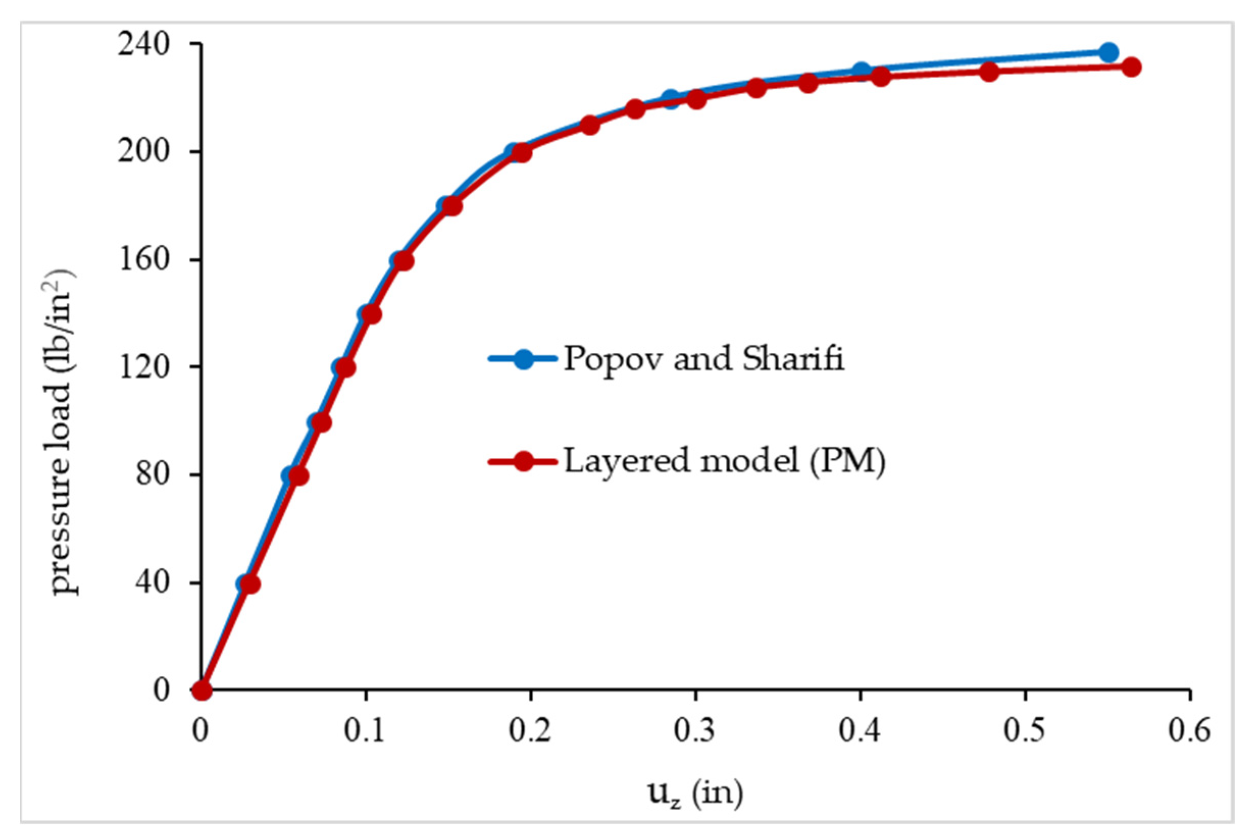
To compare the capability of the present model, the elastoplastic analysis was carried out by considering the proposed application of Popov and Sharifi [
15]: a pressure vessel with torispherical ends made of isotropic material, subjected to a radial pressure load. The dimensions were as follows: radius of curvature of the spherical crown R = 100 in, ϕ
0 = 27.89°, cylinder diameter D = 100 in, radius of the toroidal part r = 6 in and thickness t = 0.8 in. The material properties were as follows: E = 30 × 10
6 lb/in
2 and
σY = 30 × 10
3 lb/in
2. In
Figure 10, the results obtained with the present model and the results obtained by the authors mentioned before are shown. A very good agreement was observed.
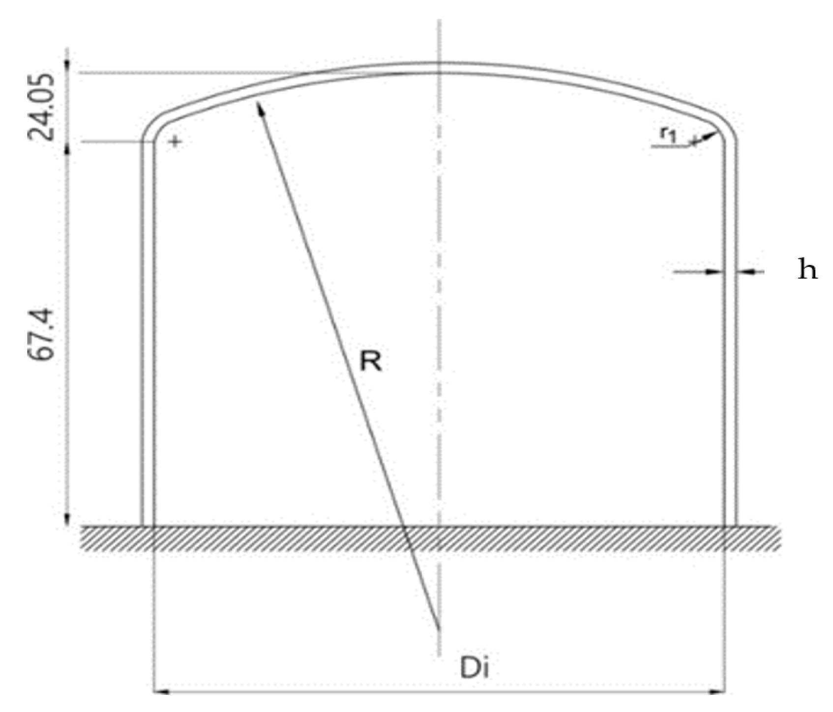
The static elastoplastic analysis of an FGM cylindrical pressure vessel with a torispherical end was performed. The constituents were zirconia and stainless steel, i.e., ZrO
2/SUS304, at a temperature of 300 K. This structure is represented in
Figure 11, where R = D
i = 135 mm, t = 1.27 mm, r
1 = 10.1 mm, and is subjected to an inner pressure load.
The material properties of the constituents were as follows:
= 207.7877 GPa,
= 0. 3175,
= 8160 kg/m
3,
= 168.0629 GPa,
= 0.2978 and
= 5700 kg/m
3. The yield stress for SUS304 was
= 400 MPa and the stress–strain transfer parameter was q* = 90 × 10
9 Pa. The gradient index considered was
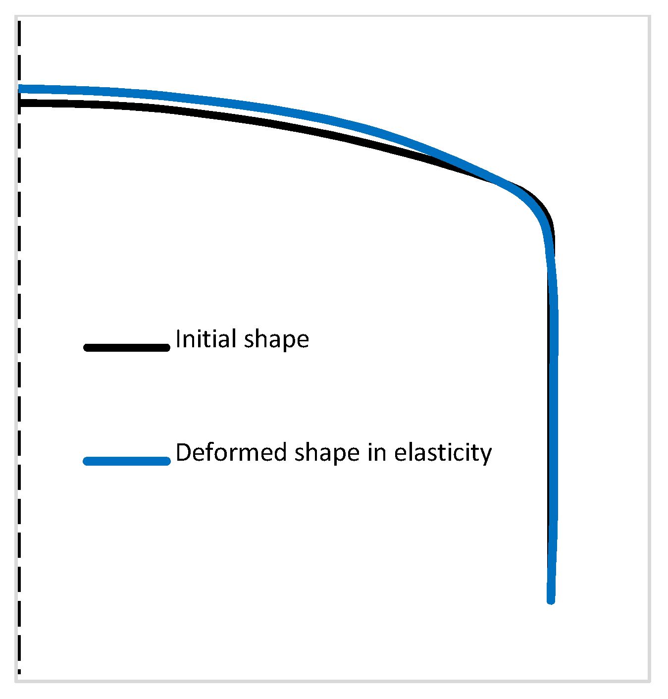
p = 0.5. The initial mass was m = 0.379 kg. The deformed shape (with u
z enlarged 10 times) of the toroidal shell, considering an internal pressure of 2 MPa, is presented in
Figure 12.
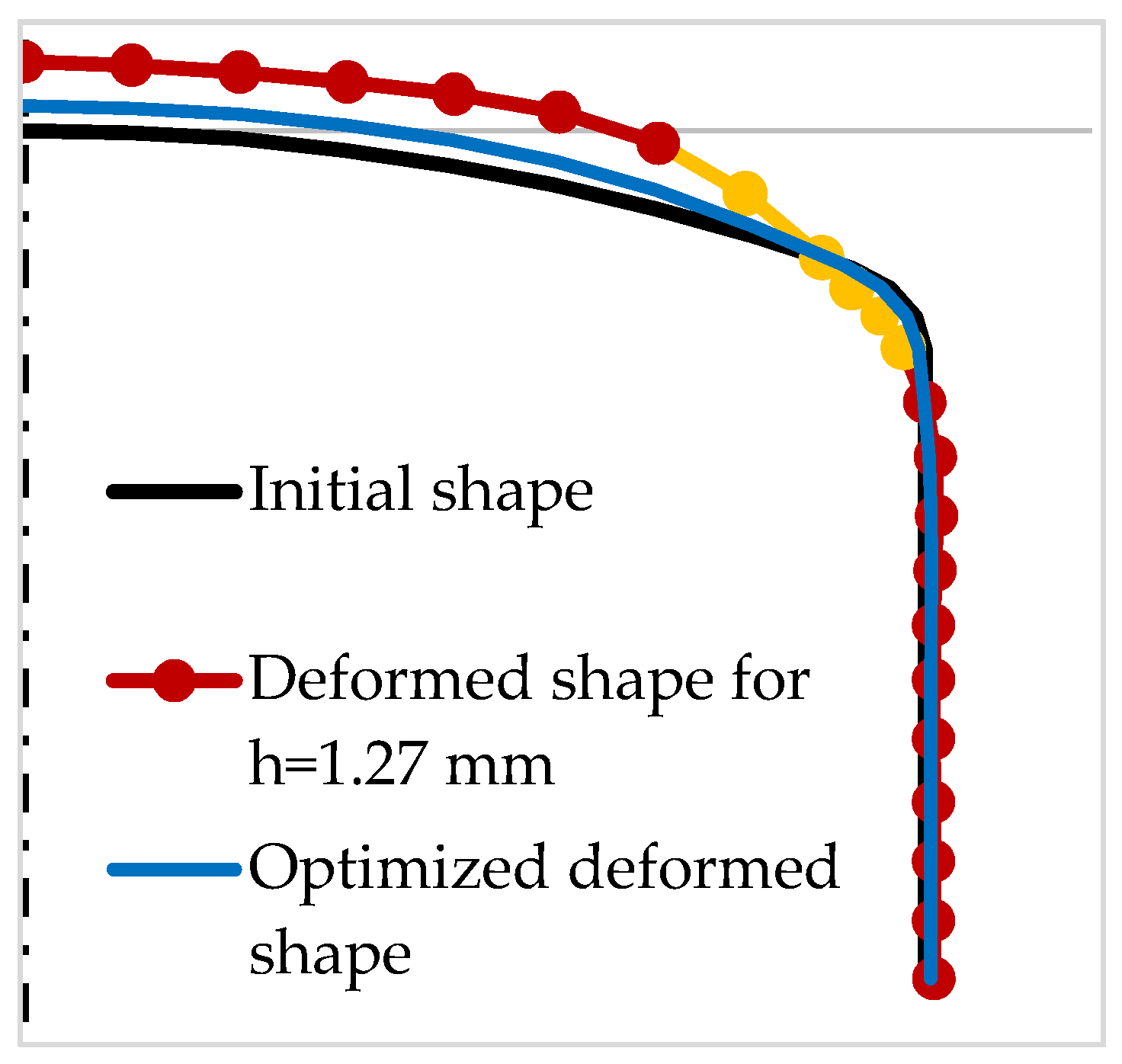
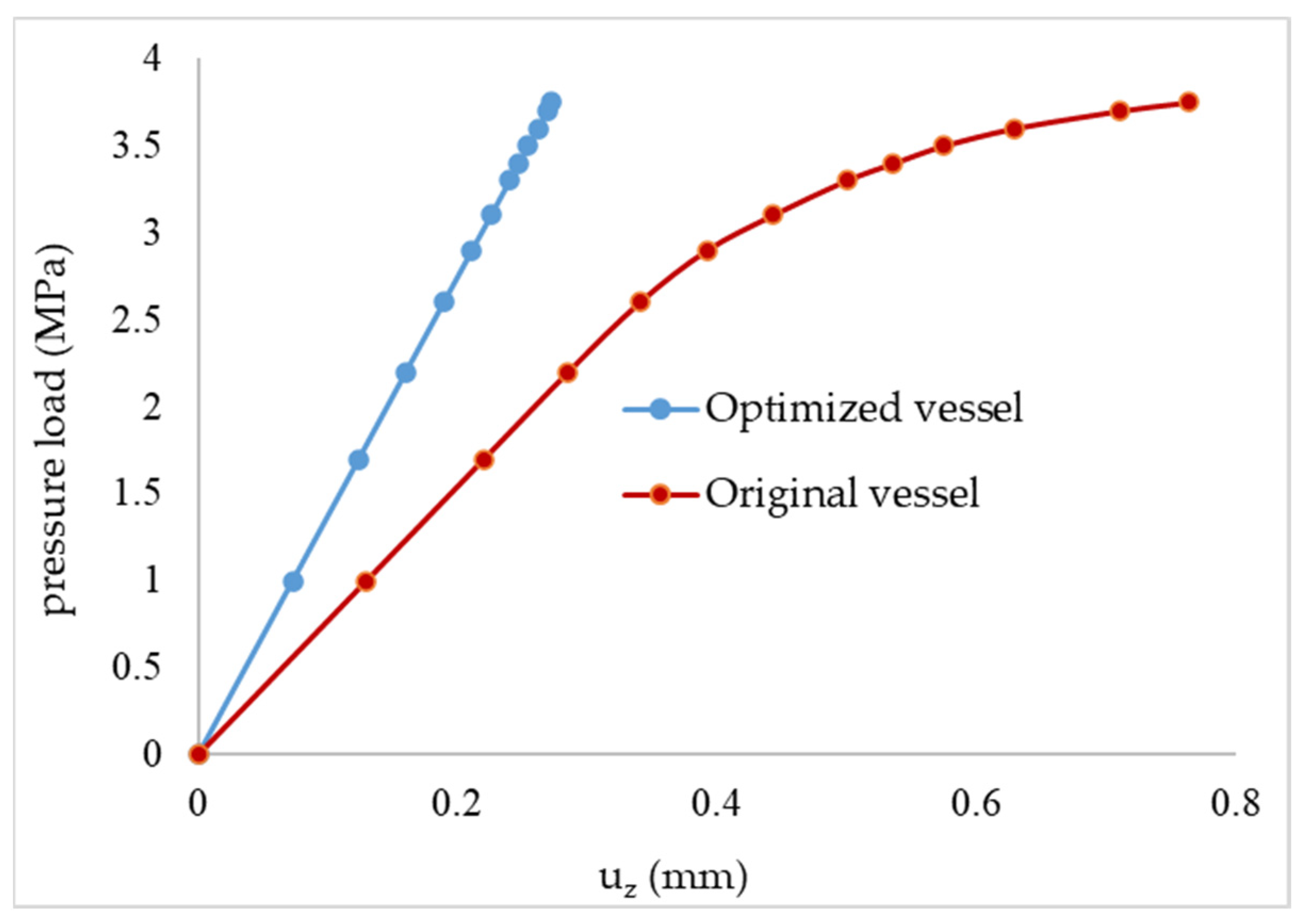
The optimization was performed once more by considering the objective function, i.e., the mass of the vessel, and the constraint, i.e., the effective stress. It was required that for the load level of 3.75 MPa, the structure should not display elastoplastic behaviour. The results obtained, as presented in
Table 5, were as follows: minimum thickness h = 2.0 mm, which corresponded to a mass m = 0.597 kg, and a maximum effective stress equal to 395.8 MPa and a yield stress equal to 395.8 MPa. For index
p = 0.5, the deformed shapes (enlarged 10 times), considering h = 1.27 mm and optimized h = 2.0 mm, are presented in
Figure 13, with the plastic zone in yellow. The respective load–displacement curves for the apex are shown in
Figure 14.
7.5. Elastoplastic Analysis of an FGM Spherical Cap under Radial Pressure
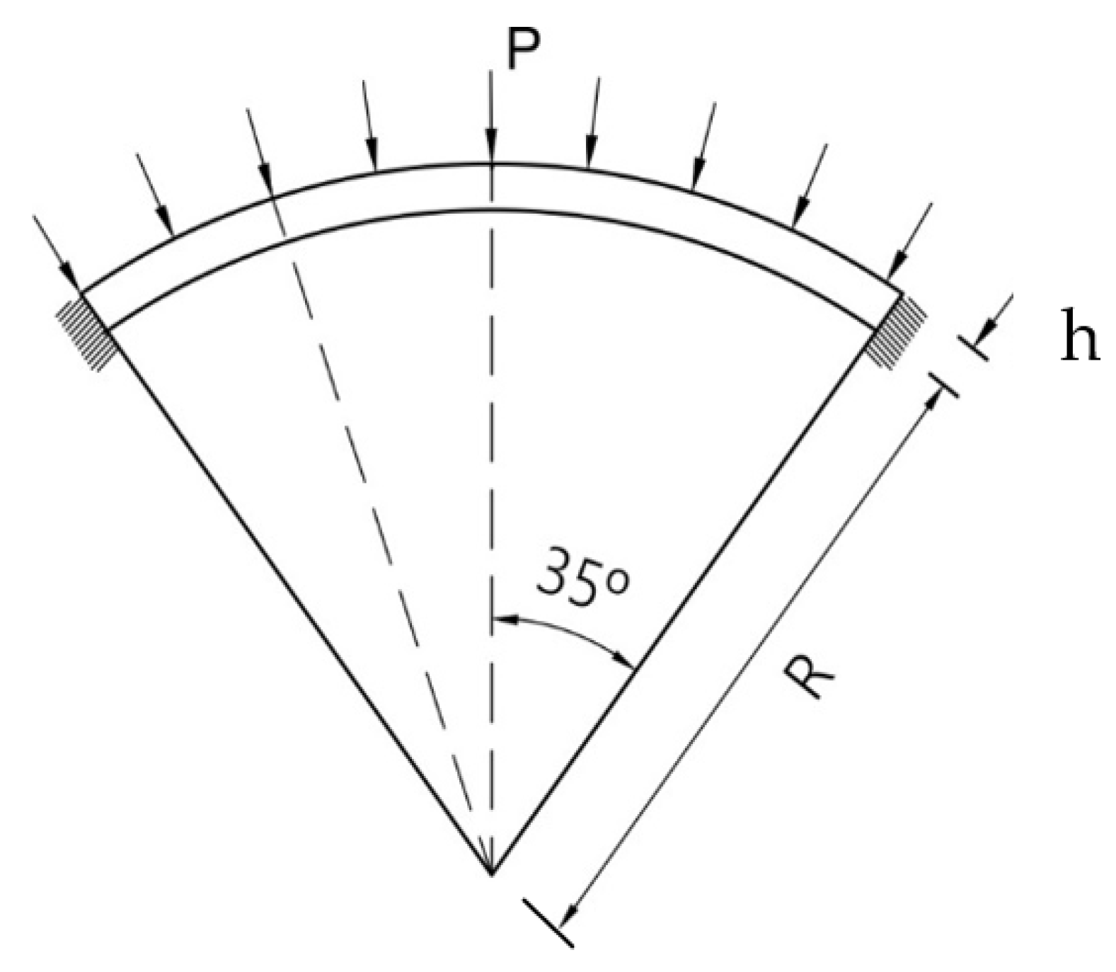
A clamped spherical cap (
Figure 15) with a radius of curvature R = 2.286 m, thickness h = 0.0762 m, half-opening angle
, made of constituents zirconia and aluminium (Em = 70.0 × 10⁹ N/m
2,
= 0.3, ρm = 3000 kg/m
3, Ec = 151.0 × 10⁹ N/m
2,
= 0.3, ρc = 2700 kg/m
3) and subjected to an outer radial pressure load was considered. The yield stress for aluminium was
= 250 MPa and q* = 80 × 10
9. First,
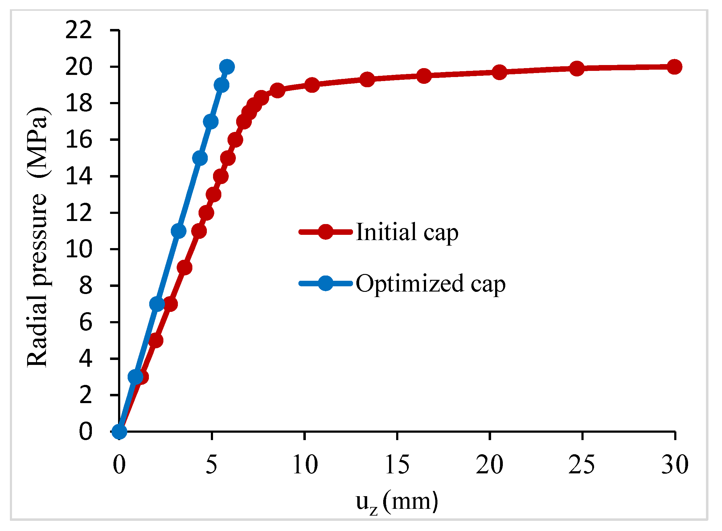
p = 1.0 was considered and the initial mass was m = 1288.34 kg. Next, the optimization was performed for the load level of 20 MPa, and the respective load–displacement curves are shown in
Figure 16. Afterwards, different gradient indexes were considered. For the spherical caps with exponent indexes
p = 2.0 and 5.0, this load level was not reached because they collapsed before the uniform radial external pressure of 20 MPa could be achieved, as summarized in
Table 6. The spherical cap for
p = 2.0 collapsed at 18.90 MPa and u
z = 30.2 mm, and for
p = 5.0, it collapsed at 17.20 MPa and u
z = 30.5 mm.
In addition, we considered the case of the spherical cap divided into two groups of elements to allow for different thicknesses in each group. Group 1 had the elements 1, 2 and 3, starting at the apex, and group 2 had the elements 4, 5, 6 and 7. The gradient index was taken as
p = 1.0.
Table 7 shows the results obtained, where it is observed that by allowing for different thicknesses in the structure, a better optimal design was reached.
8. Conclusions
The elastoplastic analysis and optimization of axisymmetric shells made of functionally graded material under axisymmetric loading were performed in this work.
The simple finite element model for axisymmetric shells used in this work required only a reduced number of finite elements to model even complex axisymmetric structures, and the discrete approach of virtual layers used to model the continuous variation of the mechanical properties through the thickness was shown to be sufficiently accurate and efficient. These are important requisites of a finite element model to be integrated into a gradient-based optimization procedure. Therefore, we concluded that the present numerical optimization package can be successfully applied for the elastoplastic design of FGM axisymmetric shell structures.
The simple numerical optimization problems for the elastoplastic design of axisymmetric shell structures can be used by researchers for comparison purposes, considering the scarcity of these studies in the literature.
The optimization examples shown in this paper showed that the gradient index had a great influence on the optimal solutions, which was due to the dependency of all the mechanical properties of this parameter (see
Table 2 and
Table 6). The presented optimization scheme demonstrated its ability to efficiently find a suitable design that avoided the elastoplastic behaviour of the FGM structure and calculate the appropriate thickness for a given
p-index value and loading condition.
Author Contributions
Conceptualization, J.S.M.; methodology, J.S.M.; software, J.S.M.; optimization software, J.H., validation, J.S.M. and A.L.A.; formal analysis, all authors; investigation, all authors; resources, all authors; data curation, J.S.M.; writing—original draft preparation, J.S.M.; writing—review and editing, V.F.C.; supervision, C.M.S.; project administration, C.M.S. All authors read and agreed to the published version of the manuscript.
Funding
This research was funded by FCT, Fundação para a Ciência e Tecnologia, through IDMEC under LAETA, project UIDB/50022/2020, and CNPq, CAPES AND FAPERJ, from Brazil.
Institutional Review Board Statement
Not applicable.
Informed Consent Statement
Not applicable.
Data Availability Statement
Data supporting the reported results can be obtained from the first author.
Acknowledgments
The authors dedicate this paper to the memory of José Herskovits Norman (1945–2022), who sadly passed away on 20 June 2022. He was a world-leading academic and distinguished expert in the fields of multidisciplinary optimization, non-linear programming, solid mechanics, finite element techniques, advanced composite materials, computational methods and characterization of material identification properties. We extend our condolences to his wife and family; his colleagues at COPPE-UFRJ Federal University of Rio de Janeiro, Brazil; and to all his friends and colleagues all over the world. He was a friend of the authors and influenced their professional careers through his research collaboration and advice.
Conflicts of Interest
The authors declare no conflict of interest.
References
- Reddy, J.N.; Wang, C.M.; Kitiporncha, S. Axisymmetric bending of functionally graded circular and annular plates. Eur. J. Mech. A/Solids 1999, 18, 185–199. [Google Scholar] [CrossRef]
- Li, X.Y.; Ding, H.J.; Chen, W.Q. Elasticity solutions for a transversely isotropic functionally graded circular plate subject to an axisymmetric transverse load qrk. Int. J. Solids Struct. 2008, 45, 191–210. [Google Scholar] [CrossRef]
- Tran, L.V.; Ferreira, A.J.M.; Nguyen-Xuan, H. Isogeometric analysis of functionally graded plates using higher-order shear deformation theory. Compos. Part B 2013, 51, 368–383. [Google Scholar] [CrossRef]
- Thai, C.H.; Kulasegaram, S.; Tran, L.V.; Nguyen-Xuan, H. Generalized shear deformation theory for functionally graded isotropic and sandwich plates based on isogeometric approach. Comput. Struct. 2014, 141, 94–112. [Google Scholar] [CrossRef]
- Zhang, D.G.; Zhou, H.M. Nonlinear bending analysis of FGM circular plates based on physical neutral surface and higher-order shear deformation theory. Aerosp. Sci. Technol. 2015, 41, 90–98. [Google Scholar] [CrossRef]
- Moita, J.S.; Mota Soares, C.M.; Mota Soares, C.A.; Ferreira, A.M. Elastoplastic and nonlinear analysis of Functionally Graded axisymmetric shell structures under thermal environment, using a conical frustum finite element model. Compos. Struct. 2019, 226, 111186. [Google Scholar] [CrossRef]
- Moita, J.S.; Araújo, A.L.; Correia, V.M.; Mota Soares, C.M.; Herskovits, J. Material Distribution and Sizing Optimization of Functionally Graded Plate-Shell Structures. Compos. Part B 2018, 142, 263–272. [Google Scholar] [CrossRef]
- Cho, J.R.; Shin, S.W. Material composition optimization for heat-resisting FGMs by artificial neural network. Compos. Appl. Sci. Manuf. 2004, 35, 585–594. [Google Scholar] [CrossRef]
- Chen, B.; Tong, L. Thermomechanically coupled sensitivity analysis and design optimization of functionally graded materials. Comput. Methods Appl. Mech. Eng. 2005, 194, 1891–1911. [Google Scholar] [CrossRef]
- Xia, Q.; Wang, M.Y. Simultaneous optimization of the material properties and the topology of functionally graded structures. Comput.-Aided Des. 2008, 40, 660–675. [Google Scholar] [CrossRef]
- Ashjari, M.; Khoshravan, M.R. Mass optimization of functionally graded plate for mechanical loading in the presence of deflection and stress constraints. Compos. Struct. 2014, 110, 118–132. [Google Scholar] [CrossRef]
- Wang, Z.W.; Zhang, Q.; Xia, L.Z.; Wu, J.T.; Liu, P.Q. Stress analysis and parameter optimization of an FGM pressure vessel subjected to thermo-mechanical loading. Proc. Eng. 2015, 130, 374–389. [Google Scholar] [CrossRef]
- Shabana, Y.M.; Elsawaf, A.; Khalaf, H.; Khalil, Y. Stresses minimization in functionally graded cylinders using particle swarm optimization technique. Int. J. Press. Vessel. Pip. 2017, 154, 1–10. [Google Scholar] [CrossRef]
- Franco Correia, V.M.; Aguilar Madeira, J.F.; Araújo, A.L.; Mota Soares, C.M. Multiobjective optimization of ceramic-metal functionally graded plates using a higher order model. Compos. Struct. 2018, 183, 146–160. [Google Scholar] [CrossRef]
- Popov, E.P.; Sharifi, P. A refined curved element for thin shells of revolution. Int. J. Numer. Methods Eng. 1971, 3, 495–508. [Google Scholar] [CrossRef]
- Zienkiewics, O.C.; Bauer, J.; Morgan, K.; Onate, E. A simple and efficient element for axisymmetric shells. Int. J. Numer. Methods Eng. 1977, 11, 1545–1558. [Google Scholar] [CrossRef]
- Bao, G.; Wang, L. Multiple cracking in functionally graded ceramic/metal coatings. Int. J. Solids Struct. 1995, 32, 2853–2871. [Google Scholar] [CrossRef]
- Jin, Z.H.; Paulino, G.H.; Dodds, R.H., Jr. Cohesive fracture modelling of elastic–plastic crack growth in functionally graded materials. Eng. Fract. Mech. 2003, 70, 1885–1912. [Google Scholar] [CrossRef]
- Nayak, G.C.; Zienckiewics, O.C. Elastoplastic stress analysis. A generalization for various constitutive relations including strain softening. Int. J. Numer. Methods Eng. 1972, 5, 113–135. [Google Scholar] [CrossRef]
- Ilyushin, A.A. Plasticité-Deformations Elasto-Plastic Stress Analysis; Eyrolles: Paris, France, 1956. [Google Scholar]
- Owen, D.R.J.; Hinton, E. Finite Element in Plasticity; Pineridge Press Ltd.: Swansea, Wales, 1980. [Google Scholar]
- Herskovits, J. Feasible Direction Interior-Point Technique for Nonlinear Optimization. J. Optim. Theory Appl. 1998, 99, 121–146. [Google Scholar] [CrossRef]
- Herskovits, J.; Mappa, P.; Goulart, E.; Mota Soares, C.M. Mathematical programming models, and algorithms for engineering design optmization. Comput. Methods Appl. Mech. Eng. 2005, 194, 3244–3268. [Google Scholar] [CrossRef]
Figure 1.
Axisymmetric shell.
Figure 1.
Axisymmetric shell.
Figure 2.
(a) Variation in Young’s modulus through the thickness; (b) variation of the yield stress through the thickness.
Figure 2.
(a) Variation in Young’s modulus through the thickness; (b) variation of the yield stress through the thickness.
Figure 3.
Conical frustum finite element.
Figure 3.
Conical frustum finite element.
Figure 4.
Through-thickness distribution of the nondimensional stress for different
p-indexes. Li et al. [
2].
Figure 4.
Through-thickness distribution of the nondimensional stress for different
p-indexes. Li et al. [
2].
Figure 5.
Load–displacement paths for the original and optimized clamped FGM plate.
Figure 5.
Load–displacement paths for the original and optimized clamped FGM plate.
Figure 6.
Toroidal shell with thickness h subjected to internal pressure p.
Figure 6.
Toroidal shell with thickness h subjected to internal pressure p.
Figure 7.
Deformed shapes of an FGM toroidal shell for index p = 1.
Figure 7.
Deformed shapes of an FGM toroidal shell for index p = 1.
Figure 8.
Deformed and optimized shapes of an FGM toroidal shell (index p = 1).
Figure 8.
Deformed and optimized shapes of an FGM toroidal shell (index p = 1).
Figure 9.
Load–displacement paths for the original and optimized toroidal shell.
Figure 9.
Load–displacement paths for the original and optimized toroidal shell.
Figure 10.
Load–displacement paths of an isotropic pressure vessel.
Figure 10.
Load–displacement paths of an isotropic pressure vessel.
Figure 11.
Pressure vessel with a torispherical end.
Figure 11.
Pressure vessel with a torispherical end.
Figure 12.
Initial and deformed shapes of the vessel.
Figure 12.
Initial and deformed shapes of the vessel.
Figure 13.
Initial and optimized deformed shapes of the vessel.
Figure 13.
Initial and optimized deformed shapes of the vessel.
Figure 14.
Load–displacement paths for the original and optimized vessel.
Figure 14.
Load–displacement paths for the original and optimized vessel.
Figure 15.
Spherical cap under radial pressure.
Figure 15.
Spherical cap under radial pressure.
Figure 16.
Load–displacement paths for the original and optimized cap.
Figure 16.
Load–displacement paths for the original and optimized cap.
Table 1.
Dimensionless central deflection of an FGM clamped circular plate.
Table 1.
Dimensionless central deflection of an FGM clamped circular plate.
| h/R | Source | Power Index p |
|---|
| 0 | 2 | 4 | 10 | 50 | 100 | Metal |
|---|
| 0.05 | Li et al. [2] | 2.561 | 1.405 | 1.284 | 1.157 | 1.049 | 1.032 | 1.015 |
| Reddy et al. [1] | 2.554 | 1.402 | 1.282 | 1.155 | 1.046 | 1.029 | 1.011 |
| Tran et al. [3] | 2.548 | 1.399 | 1.279 | 1.152 | 1.044 | 1.027 | 1.009 |
| PM | 2.560 | 1.404 | 1.283 | 1.155 | 1.043 | 1.024 | 1.015 |
| 0.1 | Li et al. [2] | 2.667 | 1.456 | 1.329 | 1.201 | 1.091 | 1.074 | 1.057 |
| Reddy et al. [1] | 2.639 | 1.444 | 1.320 | 1.190 | 1.080 | 1.063 | 1.045 |
| Tran et al. [3] | 2.630 | 1.439 | 1.314 | 1.186 | 1.076 | 1.059 | 1.042 |
| PM | 2.643 | 1.446 | 1.321 | 1.189 | 1.076 | 1.058 | 1.046 |
Table 2.
Optimization of a clamped plate.
Table 2.
Optimization of a clamped plate.
| | Initial Design | Final Design |
|---|
| p | Thickness (mm) | Mass (kg) | Thickness (mm) | Mass (kg) |
|---|
| 5.0 | h = 12.5 | 70.175 | h = 17.19 | 96.504 |
| 2.0 | h = 12.5 | 60.782 | h = 17.09 | 83.101 |
| 2.0 | h = 12.5 | 60.782 | h = 17.08 * | 83.052 |
| 1.0 | h = 12.5 | 51.394 | h = 16.83 | 69.198 |
| 0.5 | h = 12.5 | 41.983 | h = 16.45 | 55.250 |
| 0.2 | h = 12.5 | 32.574 | h = 15.93 | 41.513 |
Table 3.
Four groups of elements.
Table 3.
Four groups of elements.
| Group Number | Elements in the Group |
|---|
| 1 | 1 2 3 22 23 24 |
| 2 | 4 5 6 19 20 21 |
| 3 | 7 8 9 16 17 18 |
| 4 | 10 11 12 13 14 15 |
Table 4.
Optimization of a toroidal shell.
Table 4.
Optimization of a toroidal shell.
| | Initial Design | Final Design |
|---|
Number of
Groups | p Index and
Thickness (mm) | Mass (kg) | Thickness (mm) | Mass (kg) |
|---|
| 1 | p = 1; h = 12.70 | 335.263 | h = 13.80 | 364.301 |
| 1 | p = 1; h = 12.70 | 335.263 | h = 13.88 * | 366.402 |
| 2 | p = 1; h = 12.70 | 335.263 | h1 = 13.92
h2 = 11.21 | 300.396 |
| 4 | p = 1; h = 12.70 | 335.263 | h1 = 13.86
h2 = 9.37
h3 = 7.51
h4 = 7.32 | 222.418 |
Table 5.
Optimization of a pressure vessel with a torispherical end.
Table 5.
Optimization of a pressure vessel with a torispherical end.
| | Initial Design | Final Design |
|---|
| p | Thickness (mm) | Mass(kg) | Thickness (mm) | Mass (kg) |
|---|
| 0.5 | h = 1.27 | 0.379 | h = 2.0 | 0.597 |
Table 6.
Optimization of the spherical cap.
Table 6.
Optimization of the spherical cap.
| Initial Design | Final Design |
|---|
p Index and
Thickness (mm) | Mass(kg) | Thickness (mm) | Mass (kg) |
|---|
| p = 1.0; h = 76.2 | 1288.340 | h = 110.0 | 1859.808 |
| p = 1.0; h = 76.2 | 1288.340 | h = 110.7 * | 1871.643 |
| p = 0.5; h = 76.2 | 1311.028 | h = 97.6 | 1679.216 |
| p = 2.0; h = 76.2 | 1265.709 | h = 126 | 2092.905 |
| p = 5.0; h = 76.2 | 1243.065 | h = 140 | 2283.845 |
Table 7.
Optimization of a spherical cap (index p = 1.0).
Table 7.
Optimization of a spherical cap (index p = 1.0).
| | Initial Design | Final Design |
|---|
No. of
Groups | p Index and
Thickness (mm) | Mass(kg) | Thickness (mm) | Mass (kg) |
|---|
| 1 | p = 1.0; h = 76.2 | 1288.340 | h = 110 | 1859.808 |
| 2 | p = 1.0; h = 76.2 | 1288.340 | h1 = 110.6
h2 = 97.4 | 1688.825 |
| Disclaimer/Publisher’s Note: The statements, opinions and data contained in all publications are solely those of the individual author(s) and contributor(s) and not of MDPI and/or the editor(s). MDPI and/or the editor(s) disclaim responsibility for any injury to people or property resulting from any ideas, methods, instructions or products referred to in the content. |
© 2023 by the authors. Licensee MDPI, Basel, Switzerland. This article is an open access article distributed under the terms and conditions of the Creative Commons Attribution (CC BY) license (https://creativecommons.org/licenses/by/4.0/).


 ,
, 


