
Hydrodynamic Analysis of a Breakwater-Integrated Heaving-Buoy-Type Wave Energy Converter with an Optimal Artificial Damping Scheme


Abstract
1. Introduction
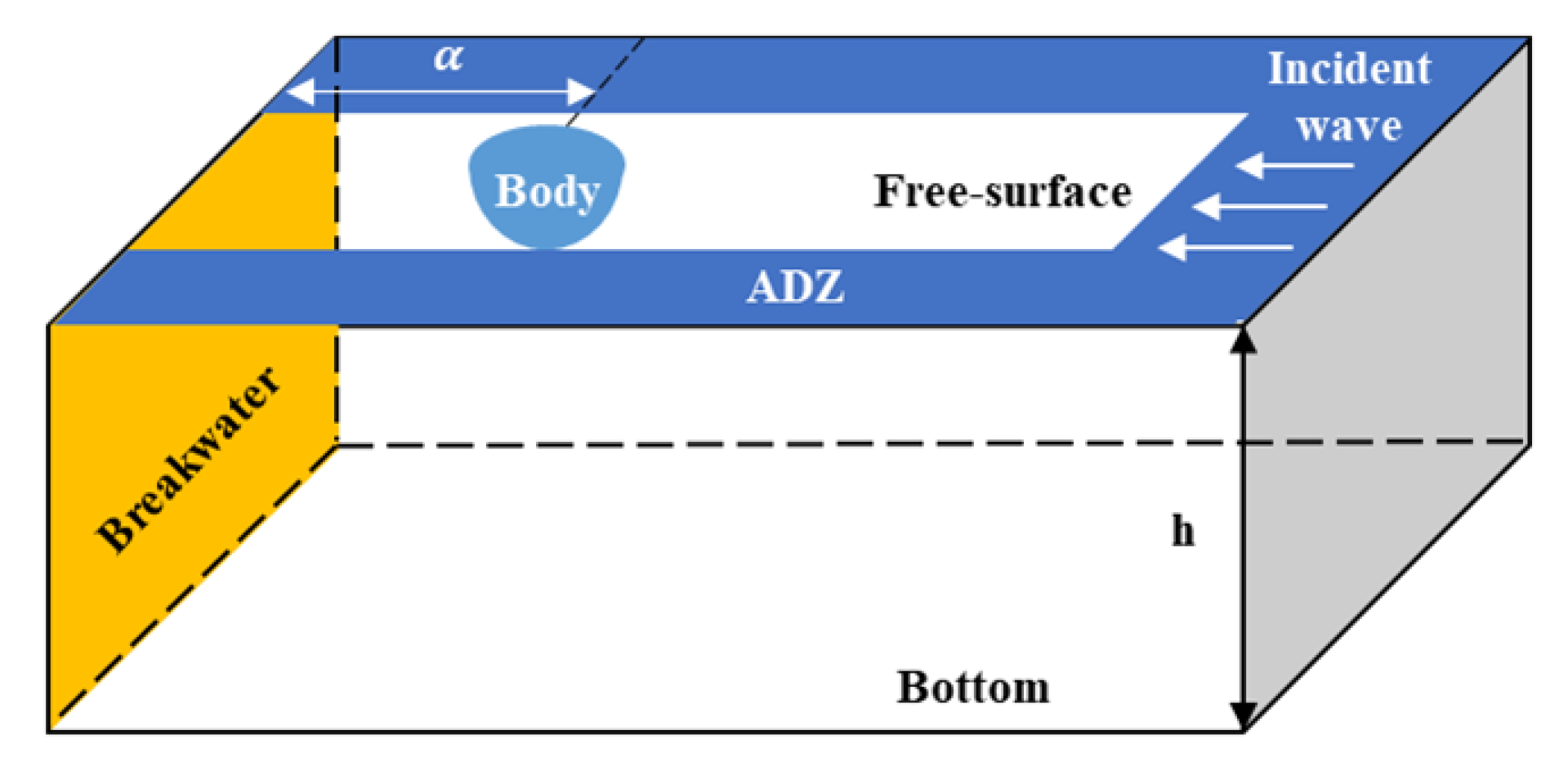
2. Numerical Model Development
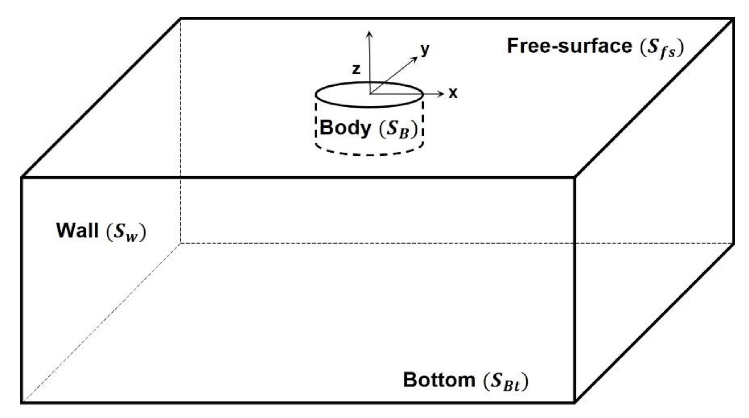
2.1. Boundary Value Problem
2.2. Boundary Condition
2.3. Equation of Motion
3. Numerical Results and Discussion
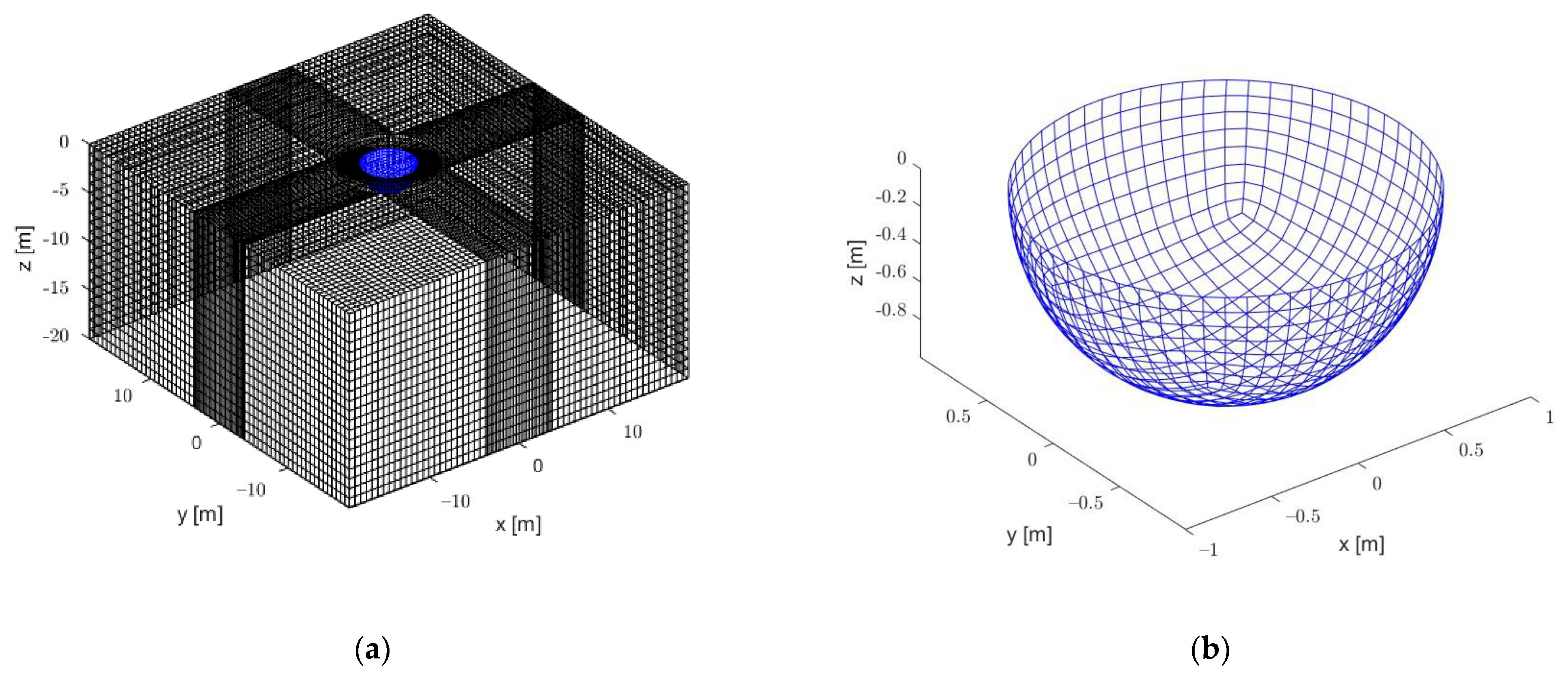
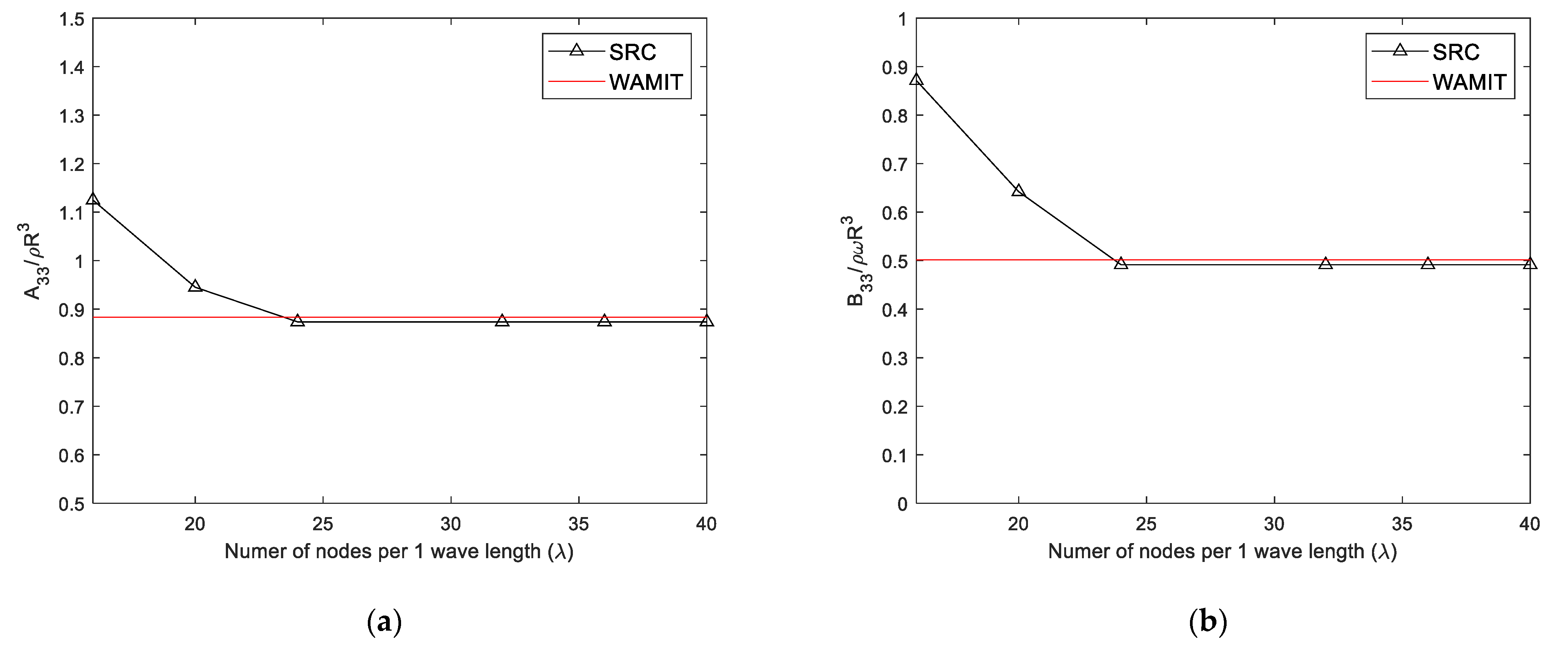
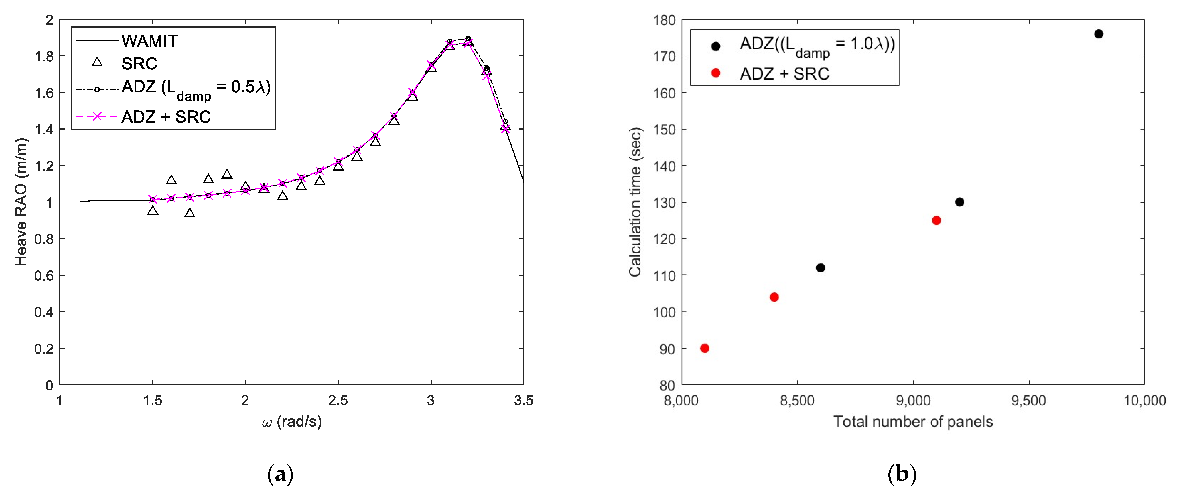
3.1. Numerical Model and Convergence Test
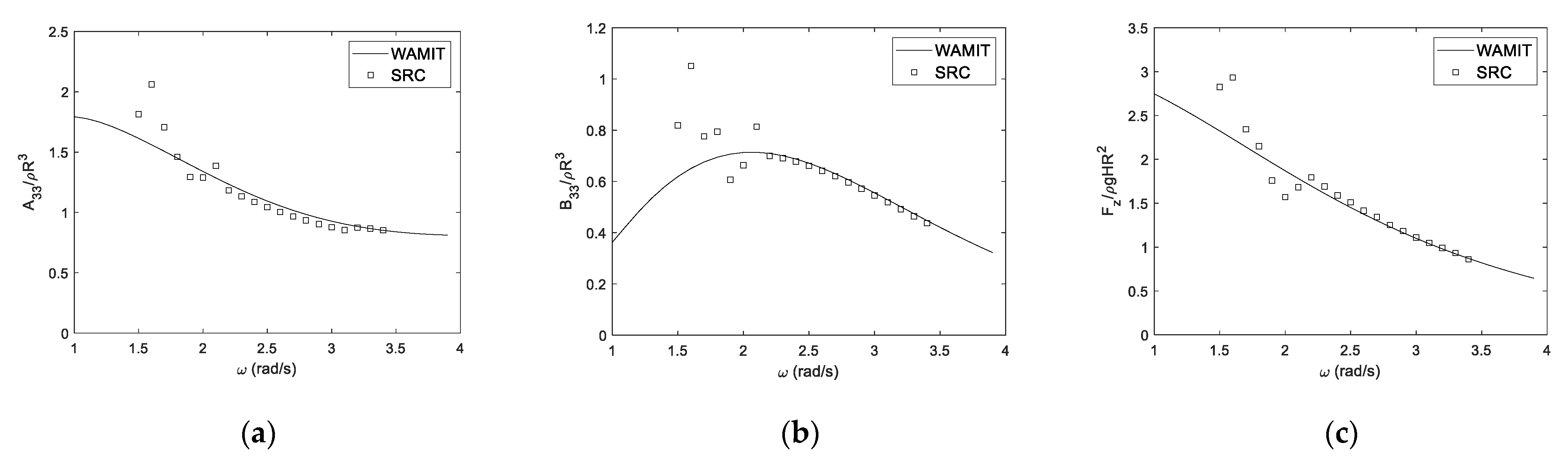
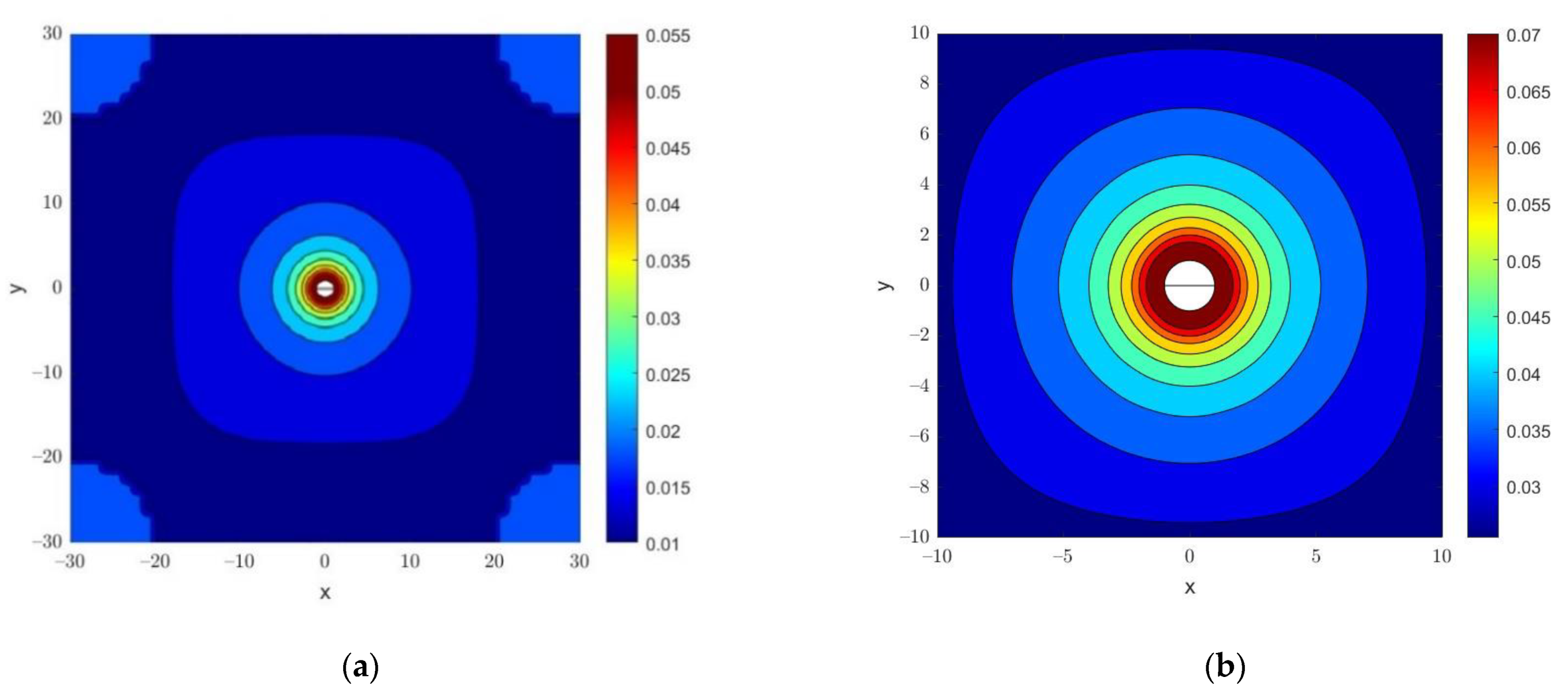
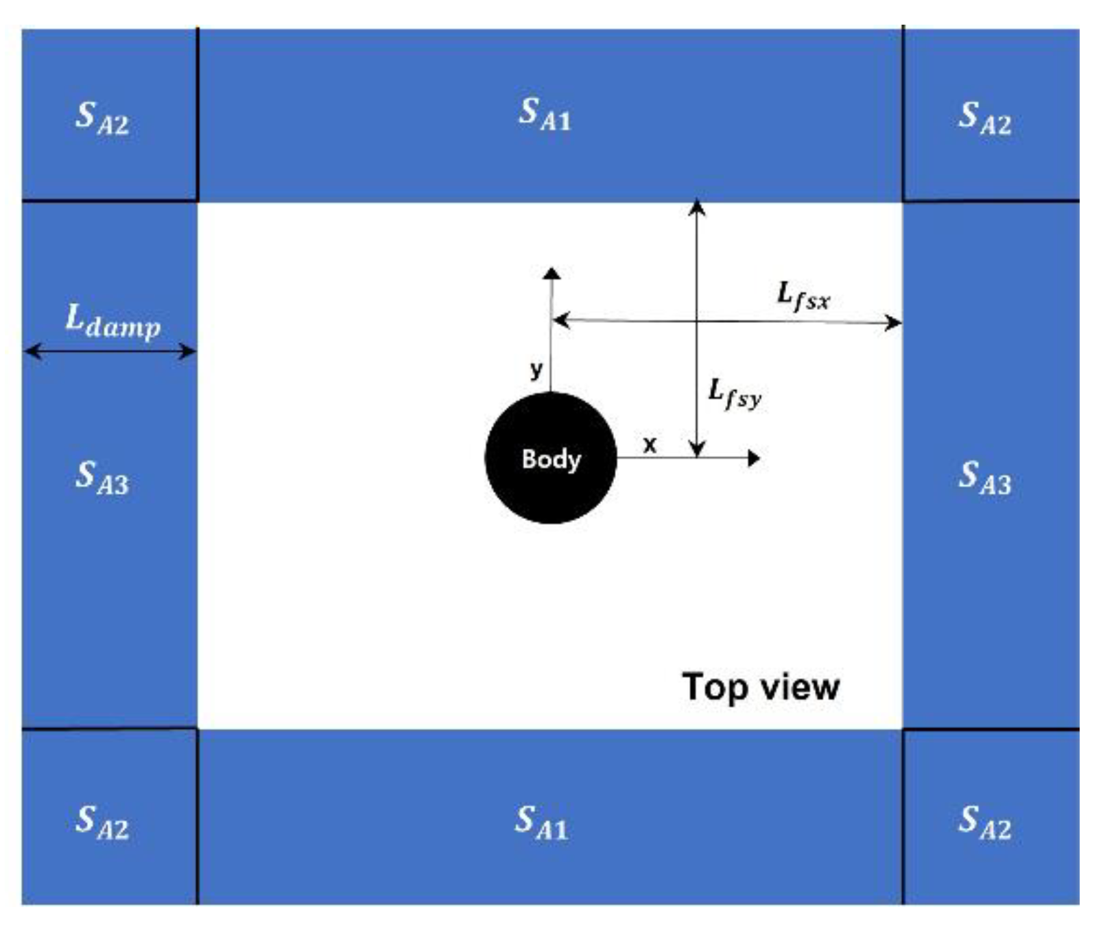
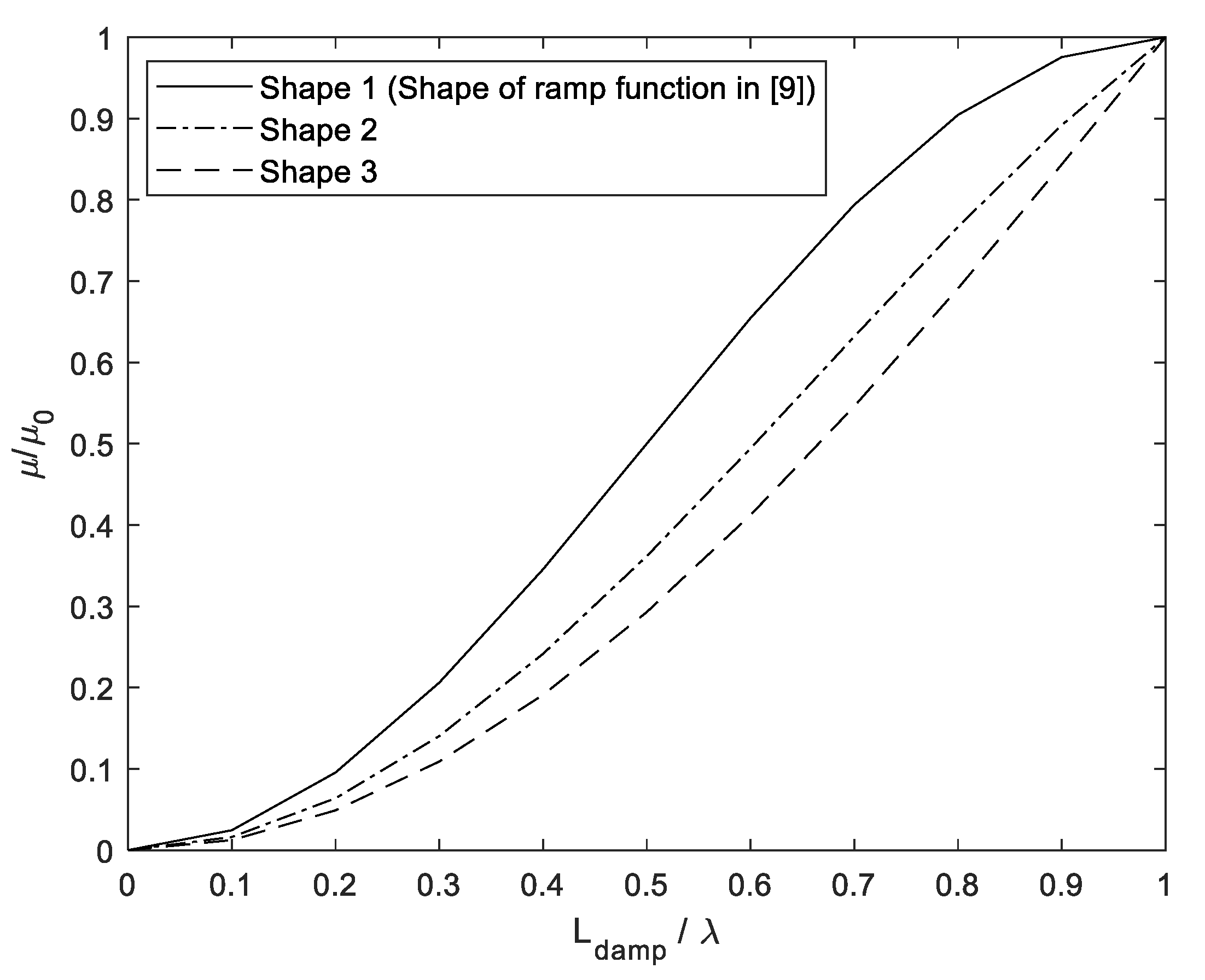
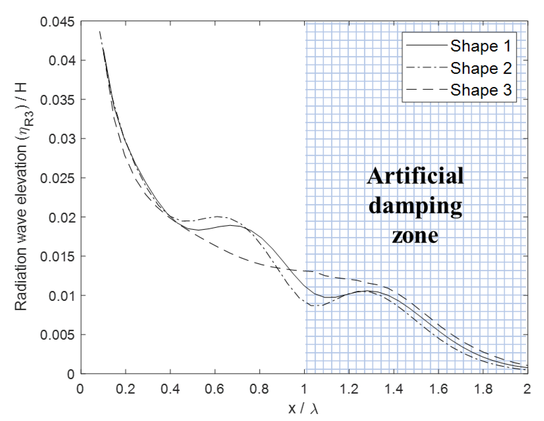
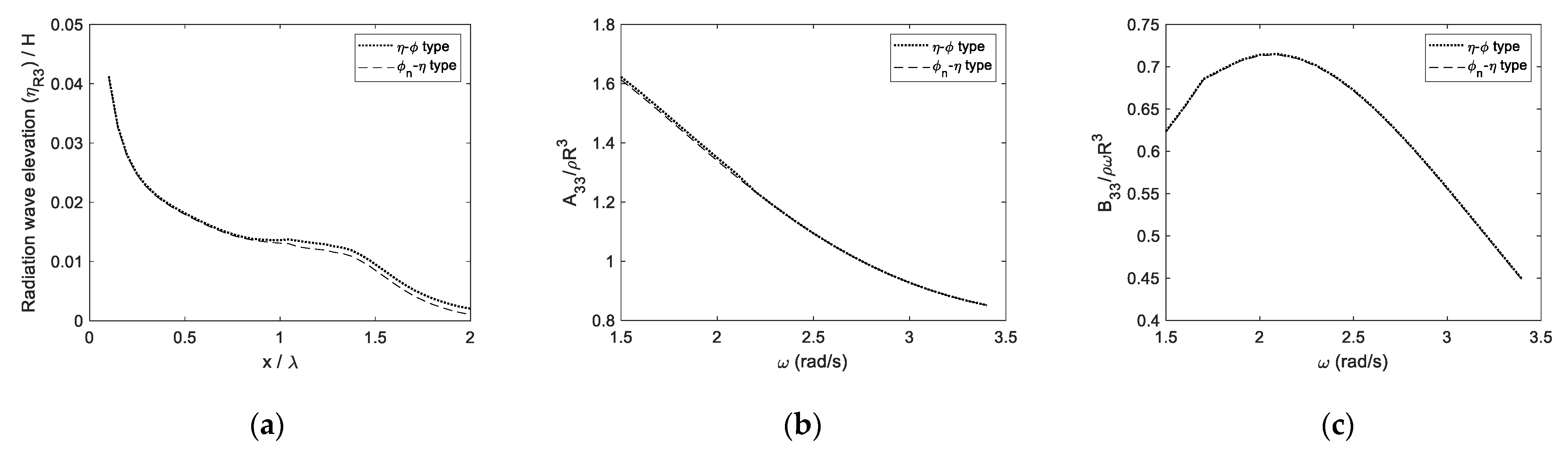
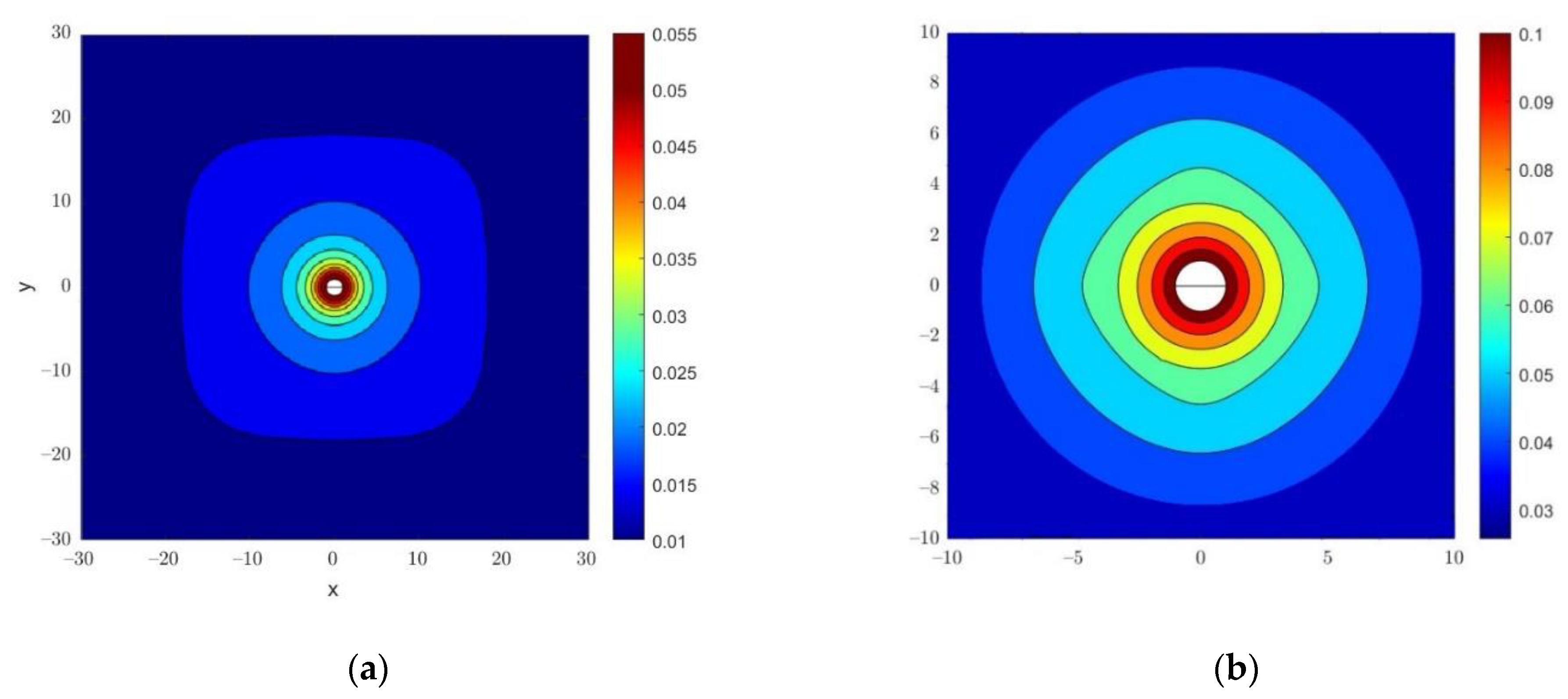
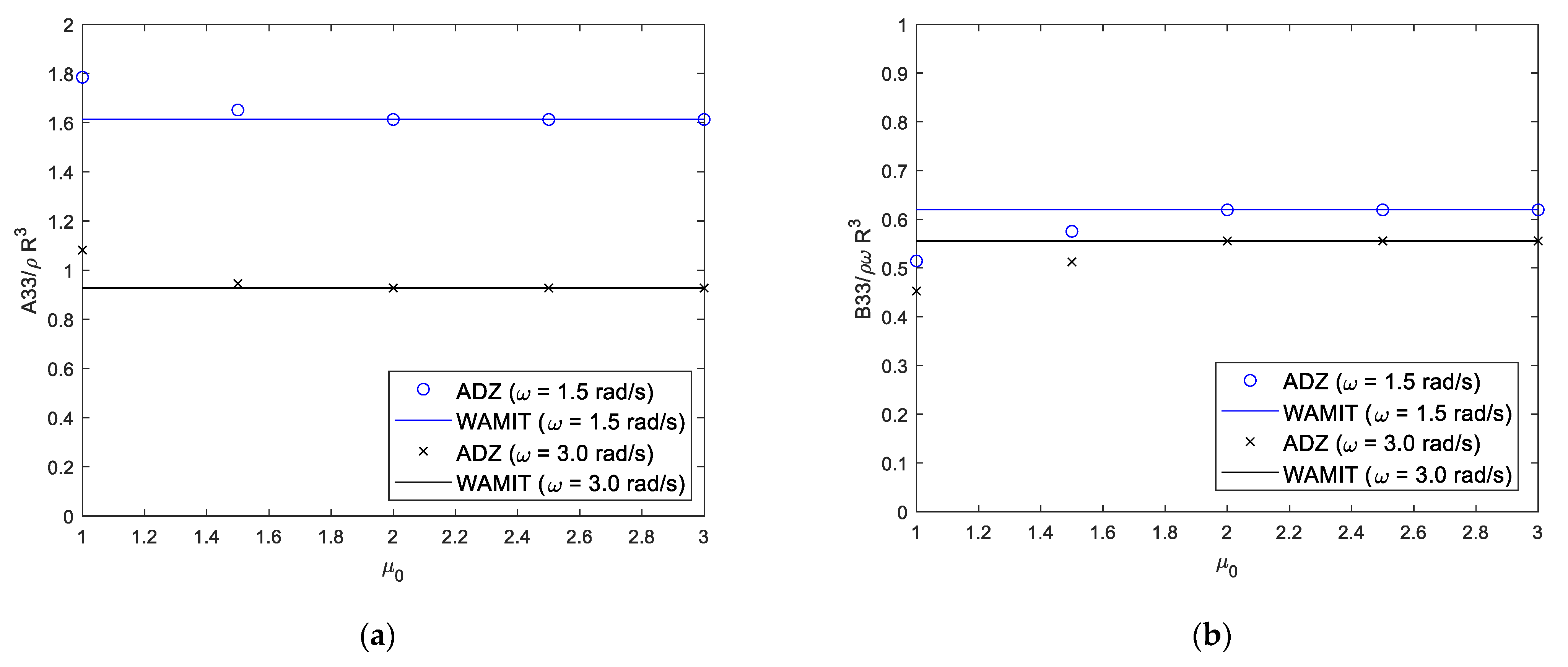
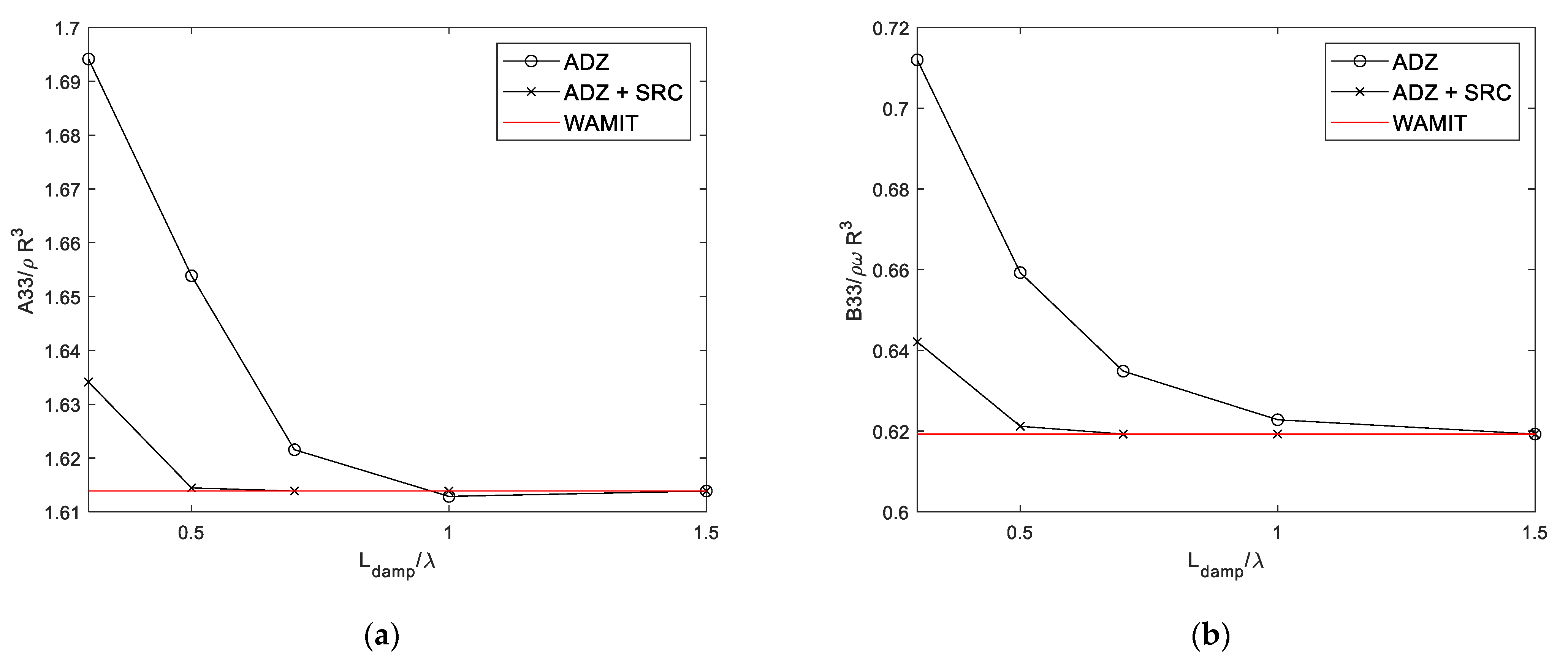
3.2. 3D-FR-NWT with Radiation Boundary Conditions
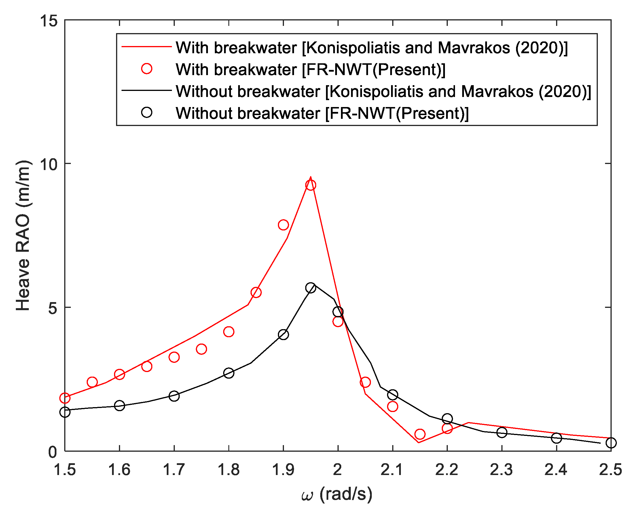
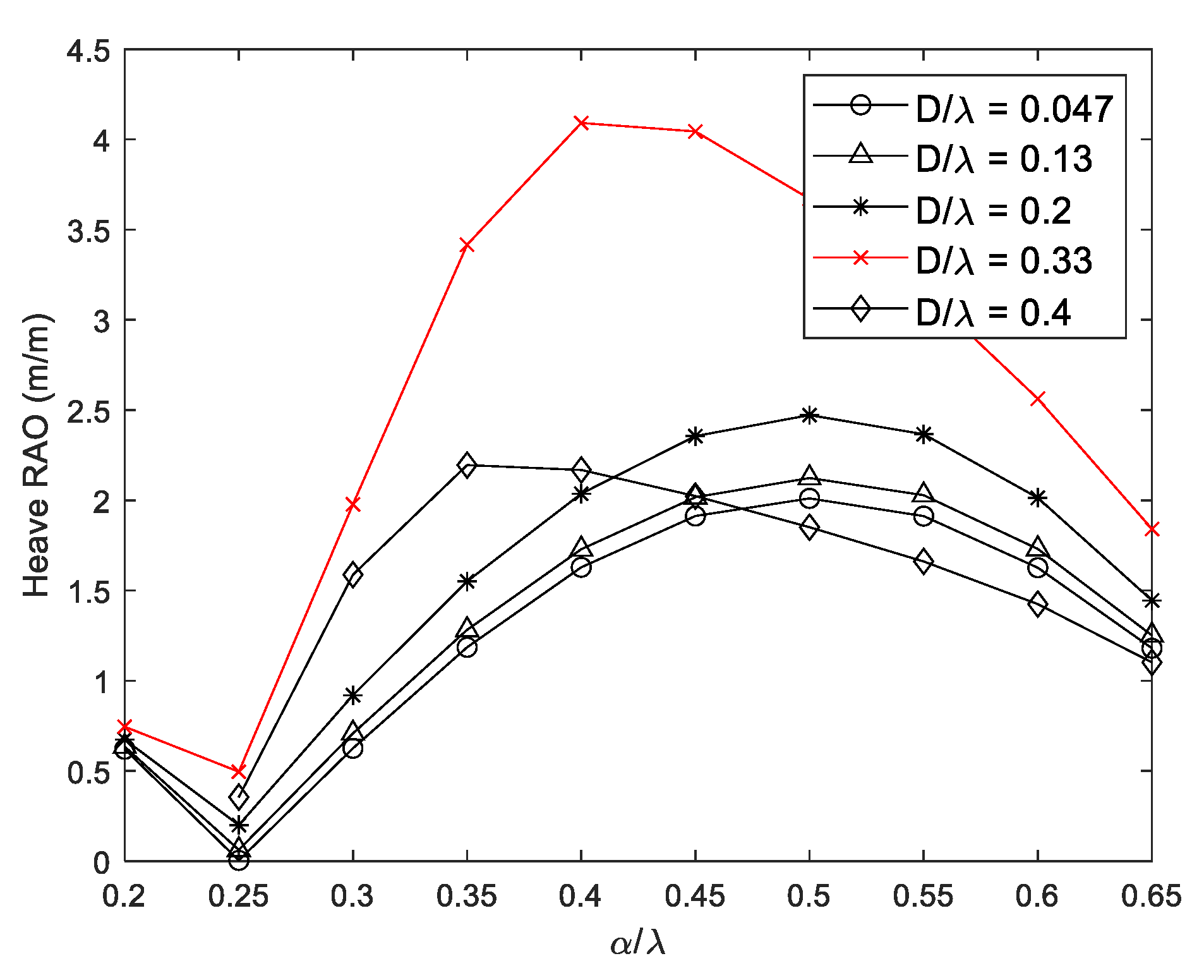
3.3. Wave Energy Converter Integrated with Breakwater
4. Conclusions
Author Contributions
Funding
Institutional Review Board Statement
Informed Consent Statement
Conflicts of Interest
Nomenclature
| Water depth | |
| Water density | |
| Length of artificial damping zone | |
| Artificial damping coefficient | |
| Wave height | |
| Wavelength | |
| Distance between wall and WEC | |
| Mass of the WEC | |
| Draft of the WEC | |
| Diameter of the WEC | |
| Wave frequency | |
| Velocity potential | |
| Gravitational acceleration | |
| Wave number at finite water depth | |
| Wave number at infinite water depth | |
| Heave-added mass | |
| Heave radiation coefficient | |
| PTO damping coefficient | |
| Radiation elevation of heave direction | |
| CW | Capture width |
| CWR | Capture width ratio |
| SRC | Sommerfeld radiation condition |
| ADZ | Artificial damping zone |
References
- Kim, S.J.; Koo, W.; Shin, M.J. Numerical and experimental study on a hemispheric point-absorber-type wave energy converter with a hydraulic power take-off system. Renew. Energy 2019, 135, 1260–1269. [Google Scholar] [CrossRef]
- Liu, H.X.; Zhang, W.C.; Zheng, X.B.; Zhang, L.; Zhang, X.W.; Cui, L. Wave energy conversion by cylinder array with a floating platform considering linear/nonlinear PTO damping. J. Mar. Sci. Technol. 2017, 22, 747–757. [Google Scholar] [CrossRef]
- Yang, H.; Min, E.H.; Koo, W. Numerical analysis of wave energy extraction performance according to the body shape and scale of the breakwater-integrated sloped OWC. J. Ocean Eng. Technol. 2021, 35, 296–304. [Google Scholar] [CrossRef]
- Poguluri, S.K.; Kim, D.; Ko, H.S.; Bae, Y.H. Performance analysis of multiple wave energy converters due to rotor spacing. J. Ocean Eng. Technol. 2021, 35, 229–237. [Google Scholar] [CrossRef]
- Cho, I.H. Effect of internal fluid resonance on the performance of a floating OWC device. J. Ocean Eng. Technol. 2021, 35, 216–228. [Google Scholar] [CrossRef]
- Ning, D.Z.; Zhao, X.L.; Chen, L.F.; Zhao, M. Hydrodynamic performance of an array of wave energy converters integrated with a pontoon-type breakwater. Energies 2018, 11, 685. [Google Scholar] [CrossRef]
- Dong, S.; Abolfathi, S.; Salauddin, D.; Tan, T.H.; Pearson, J. Enhancing climate resilience of vertical seawall with retrofitting—A physical modelling study. Appl. Ocean Res. 2020, 103, 102331. [Google Scholar] [CrossRef]
- Salauddin, D.; O’Sullivan, J.; Abolfathi, S.; Pearson, J. Eco-Engineering of Seawalls—An Opportunity for Enhanced Climate Resilience From Increased Topographic Complexity. Front. Mar. Sci. 2021, 8, 674630. [Google Scholar] [CrossRef]
- O’Sullivan, J.; Salauddin, D.; Abolfathi, S.; Pearson, J. Effectiveness of eco-retrofits in reducing wave overtopping on seawalls. Int. Conf. Coastal. Eng. 2020. [Google Scholar] [CrossRef]
- Salauddin, D.; O’Sullivan, J.; Abolfathi, S.; Dong, S.; Pearson, J. Distribution of individual wave overtopping volumes on a sloping structure with a permeable foreshore. Int. Conf. Coastal. Eng. 2020. [Google Scholar] [CrossRef]
- Dong, S.; Abolfathi, S.; Salauddin, M.; Pearson, J. Spatial distribution of wave-by-wave overtopping behind vertical seawall with recurve retrofitting. Ocean Eng. 2021, 237, 109674. [Google Scholar] [CrossRef]
- Feng, A.; You, Y.; Chi, H. An improved Rankine source panel method for three dimensional water wave problems. Int. J. Nav. Archit. 2019, 11, 70–81. [Google Scholar] [CrossRef]
- Tanizawa, K. Long time fully nonlinear simulation of floating body motions with artificial damping zone. J. Soc. Nav. Archit. Jpn. 1996, 180, 311–319. [Google Scholar] [CrossRef]
- Kim, M.W.; Koo, W.; Hong, S.Y. Numerical analysis of various artificial damping schemes in a three-dimensional numerical wave tank. Ocean Eng. 2014, 75, 165–173. [Google Scholar] [CrossRef]
- Tanizawa, K.; Naito, S. A study on parametric roll motions by fully nonlinear numerical wave tank. In Proceedings of the Seventh International Offshore and Polar Engineering Conference, Honolulu, HI, USA, 25–30 May 1997. [Google Scholar]
- Israeli, M.; Orszag, S.A. Approximation of radiation boundary conditions. J. Comput. Phys. 1981, 41, 115–135. [Google Scholar] [CrossRef]
- Cointe, R.G.P.; King, B.; Molin, B.; Tramoni, M. Nonlinear and linear motions of a rectangular barge in a perfect fluid. In Proceedings of the 18th Symposium on Naval Hydrodynamics, Ann Arbor, MI, USA, 19–24 August 1990; The National Academies Press: Washington, DC, USA, 1990. [Google Scholar]
- Clement, A.; Domgin, I.F. Wave absorption in a 2-D numerical wave basin by coupling two methods. In Proceedings of the International Workshop of Water Waves and Floating Bodies, Oxford, UK, 2–5 April 1995. [Google Scholar]
- Kim, Y. Artificial damping in water wave problems II: Application to wave absorption. Int. J. Offshore Polar Eng. 2003, 13, 94–98. [Google Scholar]
- Koo, W.; Kim, M.H. Freely floating-body simulation by a 2D fully nonlinear numerical wave tank. Ocean Eng. 2004, 31, 2011–2046. [Google Scholar] [CrossRef]
- Kim, S.J.; Koo, W. Development of a three-dimensional fully nonlinear potential numerical wave tank for a heaving buoy wave energy converter. Math. Probl. Eng. 2019, 2019, 5163597. [Google Scholar] [CrossRef]
- Kim, S.J.; Kim, M.H.; Koo, W. Nonlinear hydrodynamics of freely floating symmetric bodies in waves by three-dimensional fully nonlinear potential-flow numerical wave tank. Appl. Ocean Res. 2021, 113, 102727. [Google Scholar] [CrossRef]
- Mansour, A.M.; Williams, A.N. Numerical simulation of nonlinear wave diffraction by a vertical cylinder in a narrow flume, wide tank, and infinitely wide tank. In Proceedings of the ASME 2003 22nd International Conference on Offshore Mechanics and Arctic Engineering, Cancun, Mexico, 8–13 June 2003; pp. 653–662. [Google Scholar] [CrossRef]
- Mansour, A.M.; Williams, A.N. Simulation of outgoing waves at the boundaries of a three dimensional fully nonlinear numerical wave tank. In Proceedings of the ASME 2003 22nd International Conference on Offshore Mechanics and Arctic Engineering, Cancun, Mexico, 8–13 June 2003; pp. 643–652. [Google Scholar] [CrossRef]
- Min, E.H.; Koo, W. Radiation problem involving two-layer fluid in frequency-domain numerical wave tank using artificial damping scheme. J. Ocean Eng. Technol. 2017, 31, 1–7. [Google Scholar] [CrossRef][Green Version]
- Hess, J.L.; Smith, A.M.O. Calcualtion of nonlifting potential flow about arbitrary three-dimensional bodies. J. Ship Res. 1964, 8, 22–44. [Google Scholar] [CrossRef]
- Kim, S.J.; Koo, W. Numerical study on a multibuoy-type wave energy converter with hydraulic PTO system under real sea conditions. IEEE J. Ocean. Eng. 2020, 46, 573–582. [Google Scholar] [CrossRef]
- Kim, S.J.; Koo, W.; Kim, M.H. The effects of geometrical buoy shape with nonlinear Froude-Krylov force on a heaving buoy point absorber. Int. J. Nav. 2021, 13, 86–101. [Google Scholar] [CrossRef]
- Jin, C.; Kang, H.Y.; Kim, M.H.; Cho, I. Performance estimation of resonance-enhanced dual-buoy wave energy converter using coupled time-domain simulation. Renew. Energy 2020, 160, 1445–1457. [Google Scholar] [CrossRef]
- Lee, C.; Newman, J. WAMIT User Manual Version 7.0; WAMIT, Inc.: Chestnut Hill, MA, USA, 2013. [Google Scholar]
- Kim, S.J.; Kim, M.H.; Koo, W. Higher-order diffraction fores on vetical circular cylinders by using a three-dimensional fully-nonlinaer potential numerical wave tank. Ocean Eng. 2021, 232, 109065. [Google Scholar] [CrossRef]
- Kim, S.J.; Kim, M.H. The nonlinear wave and current effects on fixed and floating bodies by a three-dimensional fully-nonlinear numerical wave tank. Ocean Eng. 2022, 245, 110458. [Google Scholar] [CrossRef]
- Konispoliatis, D.N.; Mavrakis, S.A. Wave Power Absorption by Arrays of Wave Energy Converters in Front of a Vertical Breakwater: A Theoretical Study. Energies 2020, 13, 1985. [Google Scholar] [CrossRef]
- Kim, J.R.; Bae, Y.H.; Cho, I.H. Design of Wave Energy Extractor with a Linear Electric Generator Part I. Design of a Wave Power Buoy. J. Korean Soc. Mar. Environ. Energy. 2014, 17, 146–152. [Google Scholar] [CrossRef]
- Babarit, A. A database of capture width ratio of wave energy converters. Renew. Energy 2015, 80, 610–628. [Google Scholar] [CrossRef]
- Ulazia, A.; Penalba, M.; Ibarra-Berastegui, G.; Rinwood, J.; Sáenz, J. Reduction of the capture width of wave energy converters due to long-term seaoncal wave energy trends. Renew. Sust. Energ. Rew. 2019, 113, 109267. [Google Scholar] [CrossRef]
- Konispoliatis, D.N. Performance of an Array of Oscillating Water Column Devices in Front of a Fixed Vertical Breakwater. J. Mar. Sci. Eng. 2020, 8, 912. [Google Scholar] [CrossRef]
- Konispoliatis, D.N.; Mavrakis, S.A.; Katsaounis, G.M. Theoretical Evaluation of the Hydrodynamic Characteristics of Arrays of Vertical Axisymmetric Floaters of Arbitrary Shape in front of a Vertical Breakwater. Mar. Sci. Eng. 2020, 8, 62. [Google Scholar] [CrossRef]


| Characteristics | Value | Unit |
|---|---|---|
| Wave frequency () | 1.5–3.5 | rad/s |
| Wave height (H) | 1.0 | m |
| Radius of a floating body (R) | 1.0 | m |
| Draft of a floating body (d) | 1.0 | m |
| Water depth (h) | 20.0 | m |
| Damping Type | Free Surface Boundary Condition |
|---|---|
| type | |
| type |
| Characteristics | Value | Unit | |
|---|---|---|---|
| Body (Hemisphere) | Diameter (D) | 2.0 | m |
| Draft (d) | 1.0 | m | |
| Mass (m) | 2084 | kg | |
| Wave condition | Incident wave frequency () | 1.2–4.0 | rad/s |
| Wave height (H) | 1.0 | m | |
| Wall | Nondimensional distance between wall and body (α/λ) | 0.2–0.5 | - |
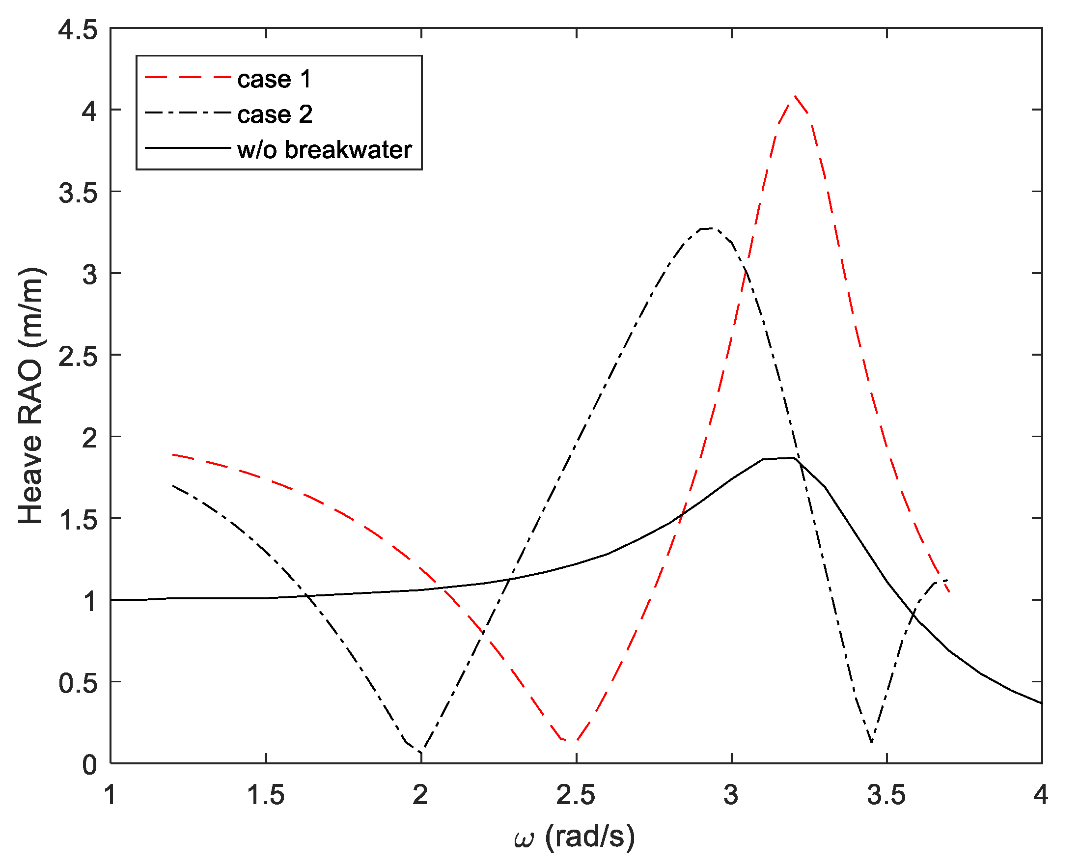
| Case Number | Motion Increment of WEC | |
|---|---|---|
| In Low-Frequency Range | In Resonance Range | |
| Case 1 | 1.87 | 2.24 |
| Case 2 | 1.70 | 2.04 |
Publisher’s Note: MDPI stays neutral with regard to jurisdictional claims in published maps and institutional affiliations. |
© 2022 by the authors. Licensee MDPI, Basel, Switzerland. This article is an open access article distributed under the terms and conditions of the Creative Commons Attribution (CC BY) license (https://creativecommons.org/licenses/by/4.0/).
Share and Cite
Jeong, H.-J.; Kim, S.-J.; Koo, W. Hydrodynamic Analysis of a Breakwater-Integrated Heaving-Buoy-Type Wave Energy Converter with an Optimal Artificial Damping Scheme. Appl. Sci. 2022, 12, 3401. https://doi.org/10.3390/app12073401
Jeong H-J, Kim S-J, Koo W. Hydrodynamic Analysis of a Breakwater-Integrated Heaving-Buoy-Type Wave Energy Converter with an Optimal Artificial Damping Scheme. Applied Sciences. 2022; 12(7):3401. https://doi.org/10.3390/app12073401
Chicago/Turabian StyleJeong, Ho-Jin, Sung-Jae Kim, and WeonCheol Koo. 2022. "Hydrodynamic Analysis of a Breakwater-Integrated Heaving-Buoy-Type Wave Energy Converter with an Optimal Artificial Damping Scheme" Applied Sciences 12, no. 7: 3401. https://doi.org/10.3390/app12073401
APA StyleJeong, H.-J., Kim, S.-J., & Koo, W. (2022). Hydrodynamic Analysis of a Breakwater-Integrated Heaving-Buoy-Type Wave Energy Converter with an Optimal Artificial Damping Scheme. Applied Sciences, 12(7), 3401. https://doi.org/10.3390/app12073401