Abstract
The thermal shock load has an important effect on the stability of thin-walled blades under high-speed operation of aircraft engines. According to the actual working conditions, the linear interpolation distribution of blade temperature is obtained by the numerical fitting method. A thermal buckling model is built to obtain the linear and nonlinear modal response of the blade through the finite element method. The results show that the blade stiffness changes under the influence of thermal buckling and the obvious torsional deformations are produced along the radial direction of the blade. Meanwhile, the largest deformation of about 1.3 mm and stress of 81 Mpa occurs on the blade tip for both the linear and nonlinear response. The buckling stress distribution and critical load factor of thermal buckling are also calculated, consistent with the rubbing part of blade. The changing radial length is the main reason for the distance reduction between the blade and casing, causing more probability of friction impact. Therefore, reasonable local thermal buckling technology is helpful to improve the design level of thermal-shock loaded blades.
1. Introduction
The rotating blades are widely used in aerospace fields owing to their lightweight, high specific strength properties, bending and reverse characteristics, and so on. When the aircraft engine operates in a high speed and temperature environment, the blades are prone to structural bending and thermal deformation and can even evolve into a rubbing fault between the blade and casing. In recent years, researchers have been investigating the enhancement of the stability of the rotor and blade system [1]. The rotating blade is a plate and shell structure. Although it has many advantages, it is easy to cause vibration, buckling instability and fatigue cracking [2]. Especially for this high-temperature plate and shell structure under a mechanical/thermal load environment, when the structural size and temperature load increases, only static analysis cannot meet the needs of engineering design. Therefore, it should be comprehensively considered from the dynamic design of plate and shell to determine the complete anti-fatigue fracture position of the blade under complex deformation. From the current research, it is agreed that the local thermal buckling deformation of high temperature plate and shell components has become one of the main failure modes under a large temperature gradient. Meanwhile, the complexity of itself and thermal shock load makes the local thermal buckling analysis process more complex and difficult. Therefore, it is necessary to study the mechanism of thermal buckling instability and establish a thermal buckling theoretical model, in line with structural characteristics and mechanical processes from the perspective of mode and stress. By obtaining the critical load and the form of instability of thermal buckling blades, it has great significance to reduce the damage from thermal–structural coupled vibration.
The engine blade is a typical thin-walled structure. In complex high temperature and high-speed environments, it is commonly regarded as a typical long elastic plate and shell structure. For the deformation of the titanium flat plate under combined thermal–acoustic load, both thermal–acoustic tests and numerical simulation were applied to obtain the more obvious effects of temperature distribution and vibration response [3]. Considering different temperature effects, Yang. [4] carried out the thermal-vibration of the thin-walled box, and dynamic strain responses were proposed to describe the vibration modals. Besides the change of modal deformations, a new question was raised regarding the kind of thermal buckling characteristics of different shells. Based on the theory of Donnell shells, the thermal buckling of thin-walled cylindrical shells is first studied to find the critical load and stress distribution [5]. Sabzikar [6] took the graded material shallow spherical shells as objects, and the thermal buckling characteristics were compared for uniform change, radial linear variation, and radial nonlinear variation, respectively. Based on the theory of pre-buckling consistency, a thin spherical shell subjected to external thermal loads was analyzed to describe its stability problem in detail [7]. For structural and mechanical characteristics of plate and shell, a Galerkin approach was adopted to obtain the deflection curve of critical load, and a local thermal buckling analysis method was established based on the initial post-buckling asymptotic theory [8]. However, the proposed method was only adapted to analyze four typical local thermal buckling models. In Ref. [9], a thermal buckling equilibrium equation of rectangular thin plates was derived using thin plate small deflection theory, which predicted the uniform temperature change from the influence of material, size parameters and critical load. Research in this area proved that, for the rotating suspension panel system, the effect of thermal shock on the axial/radial deformations and stress distribution is very important, and all these can provide an important basis for judging blade instability. Zhao et al. [10] proposed an analytical solution of dynamic characteristics to demonstrate that the thin plate was tended to produce low-frequency vibration under the combined action of thermal shock and rubbing contact. In fact, when the engine is running, the internal parts are subjected to a harsh environment, and in that case, the buckling state of structure is related to many factors [11], including the structure shape, motion state, and material properties. When the vibration modal and buckling characteristics were linked together, the changed features presented as the nonlinear response [12,13]. Through isogeometric analysis (IGA), the numerical responses of buckling were computed for laminated composite plates from thermal and mechanical loads, which illustrated that the first-order deformation did not produce a shear-locking effect [14,15]. Additionally, by incorporating with Von-Karman strains, Kabir et al. [16] developed a closed-form formulation to compare the thermomechanical buckling and post-buckling of perfect and imperfect Shape Memory Alloy (SMA) composite plates.
Over the years, the finite element method (FEM) and finite difference discretization technique (FDTD) [17] have been successfully implemented for calculating the dynamic response of thin-walled bending and torsion beams [18,19]. Meanwhile, Ramkumar et al. [20] pointed out that the free vibration and thermal buckling behavior of thick functionally graded structures could be solved effectively by FEM numerical study. Considering the processing and application characteristics of super-alloy thin-wall rectangular plates, Sha et al. [21] also put forward a coupled FEM/BEM method to improve the accuracy of simulation solution, which was more conducive to judge the dynamic responses with rising temperature. With the in-depth study of blade instability prediction during operation [22], the applicability of the existing coupling methods of buckling analysis, temperature field and FEM still need to be improved. In an actual rotational-thermal environment, the blade has more complex thermal buckling characteristics than other thin-walled structures only in a structural field. Hence, seeking an appropriate thermo-structural coupling analysis technology became very crucial for determining the stability and instability state of aeroengine blades.
In this paper, the thin-walled blades model of rotating state is first established according to the shell structure of a cantilever beam. Considering temperature effect, the equilibrium equation is deduced for different theoretical models of linear and nonlinear thermal buckling. According to the heating characteristics of engine blades, a fitting method of linear temperature distribution is proposed, simulated by the finite element method simultaneously. Furthermore, the characteristics of linear and non-linear modes are analyzed by the FEM technique, and the instability including deformations and stress distribution are determined by comparison. It could provide a feasible solution method to determine dynamics characteristics of blades under the influence of multiple fields, which has a wider effect on rubbing fault research and optimization design of high-speed rotating blades.
2. Materials and Methods
The buckling analysis is mainly used to study the structure stability under a specific load, such as a mechanical load or temperature load. Then, deformation characteristics of buckling modes are obtained to determine the critical load of structural instability. The analytical framework is presented in Figure 1.
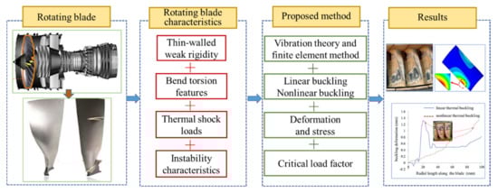
Figure 1.
The analytical framework of the paper.
2.1. Vibration Characteristics in a High Temperature Environment
In general, the high temperature environment can change the elastic properties of materials, generate thermal stress in the structure, and cause the buckling deformation of the structure. The engine blade structure works in a changing temperature environment, producing thermal stress to a varying degree. When the ambient temperature comes to a certain value, the structure is prone to experience a jumped deformation, even with rapid destruction. In that case, the changed structural stiffness matrix can be expressed as [23].
where KT is the structural stiffness matrix after the elastic properties of materials change under a high temperature environment; Kσ is an additional stiffness matrix considering the effect of high temperature thermal stress on structural stiffness; and KNL is the stiffness matrix of the cantilever plate considering geometric nonlinearity.
In Equation (1), the expression of KT is , where DT is the material elastic matrix related to a high temperature. Additionally, Kσ is expressed as , in which ST is the stress matrix related to temperature distribution.
The buckling problem caused by thermal load is a vibrational problem, bringing also structural and thermal deformation to change the stiffness of the structure at the same time. Considering the connection structure of the blades and wheel, the rotating blade can be treated as a cantilever beam of the thin-walled plate and shell structure. Distinguishing the thermal-shock load forms, the application environment of linear or nonlinear thermal buckling is clarified to judge the blade instability. Hence, the stress concentration point of the blade can be determined to obtain the critical load factor of blade.
2.2. Thermal Buckling Equilibrium Equation of a Thin-Walled Blade
When the engine is running, the rotating blades will produce uncertain bending and torsional deformation. Meanwhile, under thermal shock load, a certain section easily produces obvious pressure stress. Therefore, the profile becomes flat with a decrease of structural stiffness, which is prone to form buckling instability. In general, the bending characteristic of the blade conforms to the large disturbance bending theory of the thin-walled plate [24], as shown in Figure 2.
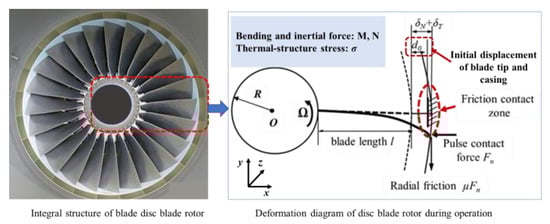
Figure 2.
The thermal deformation of a thin-walled blade [25].
Based on von Karman’s large deflection theory and plate shell theory [22], in-plane strain and curvature vectors are displayed as:
Here, µ and v are in-plane displacement, and w is the deflection of the thin plate at the equilibrium position. The ε0 represents the midplane strain vector, and κ is the midplane curvature vector. Based on the Kirchhoff hypothesis of classical plate and shell theory and Karman type geometric nonlinearity [26], the total strain is obtained in Equation (3).
In a thermal environment, the stress–strain elastoplastic relationship under uniform thermal load can be written in the following form as:
According to the deflection and deformation characteristics of plate, for the thin-blade structure, the internal force of per unit length are Nxx, Nyy, Nxy, respectively, and the three inner moments are Mxx, Myy, and Mxy. When the structure temperature rises, the internal force and internal force moment would generate the additional value. Considering the temperature rise function of , the is set as the added internal force and the is set as the added internal force moment. At this time, the Nxx, Nyy, Nxy and Mxx, Myy, Mxy can be expressed as Equations (6) and (7).
where, δ is the thickness of blades, F is the total stress function, and d is the bending strength. Meanwhile, D is equaled to be . When the thin shell assumption is adopted, the shear action is considered to obtain the midplane curvature vector κ.
Setting the blade as a cantilever structure, a specific structural equation of thermal buckling equilibrium is determined as Equation (9).
In Equation (9), the temperature bending moment is converted to , which can be also defined as . When the blades are moving, the inertia and damping forces can be produced, where f of Equation (9) is composed of three parts.
Here, is the temperature load of the blades. According to the deformation coordination equation from the literature [27], the motion equation of blade including indirect stiffness is expressed as Equation (11).
When the F is affected by transient deformation and the temperature field, the vibration mode of blade structure will change accordingly.
2.3. Modal Analysis of Thermal Buckling for the Blades
In finite elements, different from structural buckling analysis [28], the thermal buckling analysis is more prominent in the changes of displacement dT and strain εT [29]. Here, two variables are set as temperature-related variables, and the buckling equilibrium equation of unit element is given as the following:
where all parameters of Equation (12) refer to the vector representation of each element. In addition, is the node strain vector, and is the node displacement vector. Before the thermal buckling state occurs, the blade structure itself has produced the small displacement of ∆dT and internal stress of ∆σT. Thus, the buckling motion equilibrium equation in the temperature environment is converted to Equation (13).
Here, is the total stiffness matrix of thermal buckling structure. From linear thermal buckling theory, the stress stiffness matrix is directly proportional to the stress of thermal buckling film, with . Here, is the stress under the initial temperature rising load, and is the quasi-geometrical stiffness matrix. When the structure is just beginning to appear thermal buckling, multiplication of [K] and is approximately equal to zero. Therefore, Equation (13) is approximated as:
where is the thermal buckling mode. A series of λc values are set and correspond to different modes, and the minimum eigenvalue is defined as the critical buckling load factor.
2.4. Critical Load Factors of Thermal Buckling
The thin-walled structure in operation is subjected to the plane pressure of the plate. When the plane pressure of the plate reaches to a certain value, it will suddenly produce great transverse deformation, resulting in warpage and bulge of the thin-walled structure. The pressure load in this buckling or instability state is the buckling critical load of λc.
It is also divided into buckling of linear elastic instability and nonlinear instability. Due to the elastic-plastic characteristics of blade material, in the thermal buckling analysis of this paper, linear and nonlinear buckling are compared and analyzed to get the respective critical load. Combined with the boundary conditions of blade, the critical loads Pcr of multiple orders can be obtained. In practice, instability often occurs in the first order, and the instability phenomenon of the higher order is difficult to observe, so Pcr can be calculated as . The Pf and PL are defined as the critical loads, relative to two kinds of buckling, respectively, the specific change characteristics of which are presented in Figure 3.
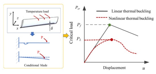
Figure 3.
The critical load of linear and nonlinear buckling analysis.
In the curve shown in Figure 3, linear and nonlinear buckling present the different load forms, with Pf > PL. Generally, the calculation of linear buckling is mainly used to solve the small displacement deformation of linear elastic materials. It is more used to determine the critical load Pf and buckling mode, but it cannot provide the situation after buckling. However, through the nonlinear buckling analysis, the instability judgment of structural models, including plastic behavior, crack, and large deformation effect, can be realized by the change curve of PL, which is of greater significance for actual structural evaluation. In this paper, the critical load factors Pf and PL of thermal buckling are calculated respectively. Combined with the blade wear characteristics, the instability characteristics of the blade are effectively determined from various aspects.
2.5. Blade Material Parameters and Temperature Distribution Interpolation
In the paper, a single rotating blade of an aero-engine is selected to perform the thermal buckling analysis. The blade material is a high-temperature alloy of K4002, with a density ρ of 8.5 × 10³ kg/m3, and other material parameters have the characteristics of changing with temperature, as displayed in Table 1.

Table 1.
Material parameters with different temperature [30].
The structural buckling mode under thermal shock load is described as the thermal buckling mode. For thermal buckling analysis of the blade, it is necessary to calculate the set T(x, y) of temperature at each point of the rotating blade. For temperature effect, the temperature boundary conditions T(x) of one dimension can be obtained by approximate interpolation [31]. A discrete interpolation method is proposed to fit the radial temperature field distribution of blades, as presented in Figure 4 and Equation (15).
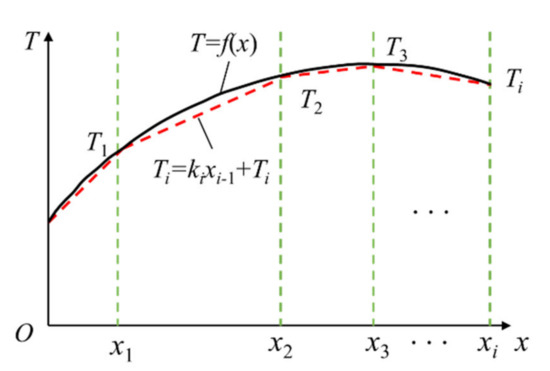
Figure 4.
The piecewise linear interpolation graph.
Set ki as the interpolation of piecewise function in any small segment, and it is presented as Equation (15).
The limit can be obtained by solving the expression of interpolation function, shown as Equation (16).
Figure 5 shows the distribution law of gas temperature and blade working temperature along blade height in the actual engine [31].
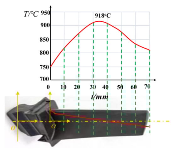
Figure 5.
Piecewise interpolation of temperature distribution along the blade [31].
From Figure 5, the temperature at both ends of the rotor blade is low, and the highest temperature occurs in the middle. It is assumed that when the turbine engine runs at the rated speed, the temperature is evenly distributed along the circumference, and the ambient temperature of each part of the blade is basically stable. Hence, linear temperature distribution is adopted and loaded on the blades, as presented in Table 2 and Figure 6.
Table 2.
Temperature interpolation data at key locations.
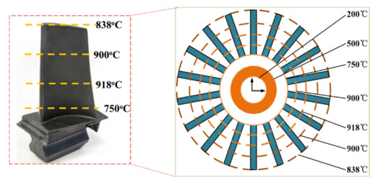
Figure 6.
Temperature distribution on the blade.
3. Results
3.1. The Linear Thermal Analysis of Blade
In order to carry out thermal buckling analysis, the thermal distribution needs to be loaded first to solve the thermal stress. According to the link mode between blade and impeller, all nodes at the bottom of the blade are rigidly coupled to limit the influence of impeller stiffness on blade structure. When the blade is rotating at high speed, the centrifugal action produces internal stress in the whole blade. Based on the definition of temperature boundary conditions, the SHELL131 hot shell element is selected for the blade body, and the solid70 hot solid element is selected for the wheel disc. Ignoring the effects of heat convection and heat radiation, the steady-state thermal analysis of the blade is carried out to obtain the temperature distribution of the blade in the stable working state, displayed in Figure 7.
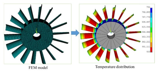
Figure 7.
Temperature distribution on the blade obtained from FEM.
From the finite element analysis in Figure 7, the disc temperature gradually increases along the radius direction from the central axis, and the blade body temperature is relatively low at the blade root and tip, and the highest temperature occurs in the middle of the blade, which is consistent with the theoretical calculation results.
3.2. The Linear Thermal Buckling Modal Response
In terms of axisymmetry of rotating structures, it is set that each constrained blade is basically affected in high-temperature operation, and a single constrained blade can be selected for thermal buckling analysis. The finite element model is established, with the 1479 elements of SHELL131 and the nodes of 3120, as shown in Figure 8 [1].
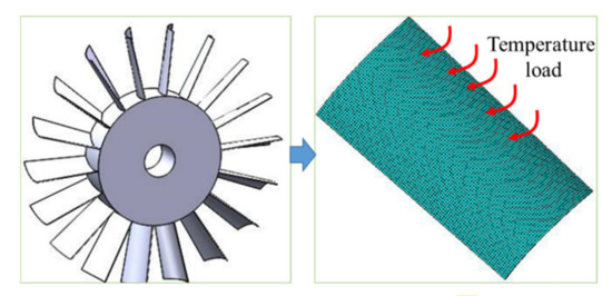
Figure 8.
The finite element model of the single blade [1].
Therefore, the unit temperature load is applied to all nodes, and the internal stress caused by multi-field action can be obtained by linear static analysis. The linear buckling analysis is carried out firstly to determine the concentration point deformation. The finite element method is adapted to calculate thermal buckling mode, where the first four orders are presented in Figure 9 [1].
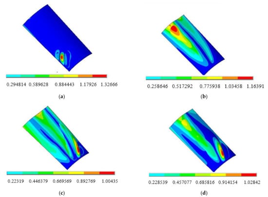
Figure 9.
The linear buckling modes of blades [1]. (a) The first-order mode; (b) the second-order mode; (c) the third-order mode; and (d) the fourth-order mode.
As can be seen in Figure 9, the effect of thermal shock on buckling modes is obvious. For the first mode buckling, the buckling response mainly occurs at the edge of the blade root, presenting the concentric ring deformation. The maximum deformation is located at the center of the concentric ring, and the displacement gradually decreases from the center to the outside. Meanwhile, for the whole blade, the slight bending only appears at the blade tip, and the deformation of other parts is basically close to zero.
Different from the first mode, the second mode is characterized by the deformation of the concentric ring, appearing in the middle of the blade tip. The maximum displacement is still in the center of concentric ring. Currently, the blade has obvious folding, which is the bending torsion coupling deformation. By the third-order and fourth-order modal buckling, the deformations are very similar. The folds are alternately distributed in the middle of the root and blade tip, while the number and area increase accordingly. Therefore, the blade root and tip are most prone to deformation and instability under thermal shock load. The occurrence of such buckling modes is related to the characteristics of blade mounting structure. Practically, the blade root is constrained by the wheel disc with longer chord length of the blade tip, and then there is insufficient support in the length direction, relatively. The internal force of the structure will accumulate rapidly, and structural stiffness reduces correspondingly. Therefore, the blade root and tip are most prone to emerging deformation and instability under thermal shock load.
3.3. The Stress Distribution of Linear Thermal Buckling
Under the action of thermal shock load, the buckling deformation of the restrained blade will also produce large local stress accumulation. By analyzing the local stress distribution, we can find the parts where the blade is prone to deformation, failure and even fracture under the influence of thermal impact load, which is of great significance to the optimal design of blade structure. Through FEM calculation, the first four orders of linear thermal buckling stress distribution are obtained, as show in Figure 10.
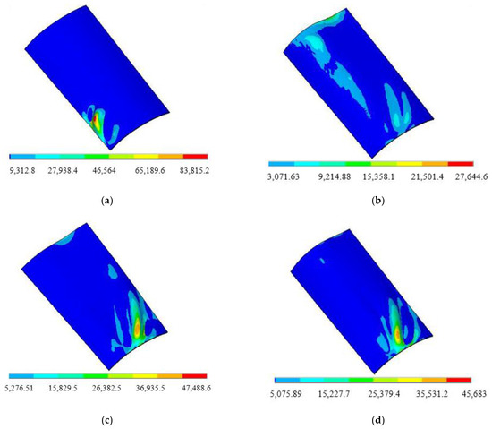
Figure 10.
The linear buckling stress distribution of blades. (a) The first-order mode; (b) the second-order mode; (c) the third-order mode; and (d) the fourth-order mode.
Under thermal shock load, the first four orders of buckling stress distribution of the blade is consistent with the corresponding buckling mode distribution, and the maximum stress position corresponds to the maximum buckling deformation. The first-order buckling stress is mainly concentrated at the edge of blade root, which is a concentric ring. The maximum stress appears in the center of the concentric ring, and the stress gradually decreases from the center to the outside, and there is no stress accumulation in other parts of the blade. The second-order buckling stress is concentrated in the middle of the blade tip and blade root, and the stress distribution is slightly folded and discontinuous. The third and fourth order buckling stresses mainly occur in the middle of the blade root, showing an obvious concentric ring, and a small increase in stress occurs at the blade tip. Therefore, the maximum buckling stress mainly occurs at the blade root and tip, which indicates that the blade root and tip are most prone to failure, or even fracture, under thermal shock load.
3.4. The Non-Linear Thermal Buckling Modal Response
To simulate the initial disturbance of the blade, the first order linear buckling deformation is reduced 500 times to small deformation. The geometric position of blade nodes are updated as the initial state of iteration. Meanwhile, the maximum deformation of linear buckling is set as the critical displacement of blade instability, which is beneficial to control the termination of calculation. In the solution, the effects of initial defects and large deformation response are considered. Then, the step-by-step iteration method is implemented to calculate the non-linear thermal buckling modal response, with deformations of first four orders shown in Figure 11 [1].
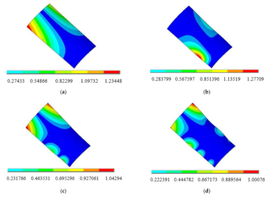
Figure 11.
The nonlinear buckling modes of the blades [1]. (a) The first-order; (b) the second-order; (c) the third-order mode; and (d) the fourth-order mode.
As exhibited in Figure 11, the first mode buckling mainly occurs at the edge of the blade tip, presenting as a twill. At the same time, there is large bending and torsional deformation, with the largest displacement change. Meanwhile, compared with the experimental analysis in Ref. [32], it is clearly found that the characteristics of nonlinear thermal buckling modes are consistent with blade tip cracking in a thermal power plant, given in Figure 12 [1].
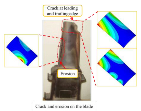
Figure 12.
The results comparison of thermal buckling analysis and Ref. [32].
For the second mode buckling, the deformation of the blade is a semi concentric ring with slight bending, mainly appearing at the edge of the blade root. Different from the above modes, in the third and fourth order modal buckling, buckling surface area gradually become larger, with the significant deformations appearing at the top edge. It is worth noticing that the range of buckling response is directly proportional to the increase of modal order, majorly distributed at the edge and tip of the blade, with a variety of deformation forms.
3.5. The Stress Distribution of Non-Linear Thermal Buckling
From nonlinear buckling analysis, the stress distributions of the first four orders are extracted to further explore the weak parts of the constrained blade under thermal shock load, as shown in Figure 13.
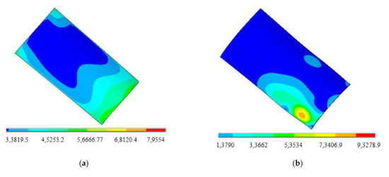
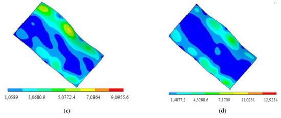
Figure 13.
The non-linear buckling stress distribution of blades. (a) The first-order, (b) the second-order, (c) the third-order mode, and (d) the fourth-order mode.
It can be seen from Figure 13 that the first-order nonlinear buckling stress is mainly distributed at the blade root and blade tip edge. The maximum stress appears at the blade edge and gradually weakens from the edge to the center. The second-order nonlinear buckling stress mainly appears at the edge of the blade root, showing a concentric ring from the center of the concentric ring. The third and fourth-order nonlinear buckling stress distribution are continuous and wide, which is connected by multiple concentric rings.
4. Discussion
4.1. The Deformation Comparison between the Linear and Non-Linear Thermal Buckling Response
In thermal buckling analysis, the first-order buckling mode is the critical state, in which buckling mode distribution can best reflect the initial state of buckling, becoming the key basis to judge the thermal instability of structures. In the paper, for the linear and non-linear thermal buckling, their first-order modal deformations along the blade are compared in Figure 14 [1].
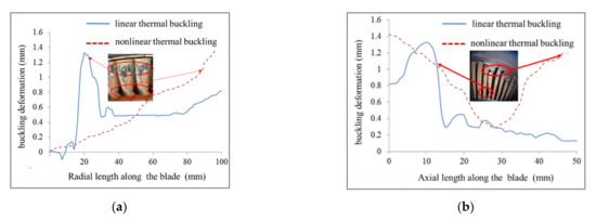
Figure 14.
The radial distribution buckling deformation along the blade. (a) The radial distribution along the blade; (b) the axial distribution along the blade.
In Figure 14a, for linear thermal buckling, the critical buckling deformation of the blade mainly occurred in the range of 15~30 mm away from the blade root and about 20 mm from the blade tip. In addition, at the leaf roots, the buckling deformation shows a peak shape. The deformation at 15 mm from the blade root will suddenly increase and reach the maximum value of 1.327 mm at 20 mm from the blade root, and then gradually decrease along radial direction from 20 mm to 50 mm. Meanwhile, the buckling deformation of the tip is an upturned shape with the maximum deformation of 0.819 mm. In nonlinear buckling, the critical buckling deformation of the blade is the warpage of the overall structure, and the deformation becomes larger gradually along the radial direction. The maximum deformation appears at the blade tip with 1.424 mm, which was 7.3% larger than maximum deformation of linear thermal buckling.
It is clearly found in Figure 14b that, along the axial direction, the range of 5~15 mm from the blade edge is the main occurrence area for critical linear thermal buckling deformation. Meanwhile, the maximum deformation is at the same position by comparison of the maximum deformation along the radial direction of Figure 14a. This also points out that the linear critical thermal buckling deformation can happen only on one side of the blade. However, critical nonlinear thermal buckling deformation is approximately symmetrical along the axial direction, and both blade tips are bent to the middle part.
4.2. The Stress Comparison between the Linear and Non-Linear Thermal Buckling Response
In order to better obtain the weak part of the blade under thermal shock load, the first-order linear and nonlinear thermal buckling competing and axial stress distribution are compared, as shown in the Figure 15.
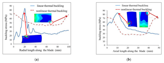
Figure 15.
The radial distribution buckling deformation along the blade. (a) The radial distribution along the blade; (b) the axial distribution along the blade.
From Figure 15, the radial distribution of linear thermal buckling stress of the blade is corresponding to the distribution of thermal buckling deformation of Figure 14. The stress at 15–30 mm away from the blade root is in the shape of a peak, with a relatively concentrated distribution. The maximum stress at 20 mm from the blade root is 83.81 MPa. In the range of about 20 mm at the blade tip, the stress decreases slightly to 32.31 MPa at the blade tip, and the stress is small relative to the blade root. The nonlinear buckling stress of the blade is approximately symmetrically distributed along the radial direction, and the maximum stress at the blade root and tip is 72.59 MPa, which is 13.39% lower than the maximum stress of linear buckling.
From the comparison of axial stress distribution, the linear buckling stress mainly occurs in the range of 5–15 mm from the blade edge along the axial direction, and is concentrated on one side of the blade. The nonlinear buckling stress distribution is still symmetrical, and reaches the maximum at both blade tips. In other words, the nonlinear buckling results show that the blade tips on both sides bear large stress and are prone to failure.
Meanwhile, the buckling instability of the blade calculated in this paper has the same distribution characteristics as the thermal fracture of the existing thin-walled blade. It is noteworthy that the blade tip is the most vulnerable part to generate buckling instability in both linear and nonlinear analysis. Therefore, more attention should be paid to the structural design and verification of the blade.
4.3. The Critical Load Factor of Linear and Nonlinear Thermal Buckling
In eigenvalue buckling analysis, the Nth-order buckling load factors are extracted. The equation is concretely expressed as:
Here, Pcr is represented as the thermal buckling load, is set as the load factor and PC is the calculated load. For linear and nonlinear buckling analysis, the first four different load factors are extracted and defined as , and , . The load factors of the first four orders of blades are shown in Table 3.
Table 3.
The critical load factor of the first four orders.
In the first order response, either linear buckling (~1.6067) or nonlinear buckling (~1.3316), are both larger than 1, which is a direct illustration of Pf > Pcr-linar and PL > Pcr-nonlinear. It is also verified that critical temperature-rise load will be greater than the maximum calculating load. Therefore, in linear thermal bucking, the blade does not lose stability under thermal shock load, and the structure also meets the stability requirements. Meanwhile, it is confirmed that the critical thermal buckling load is greater than the maximum load borne by the blades. Overall, the load factor at each order are different, as depicted in Figure 16.
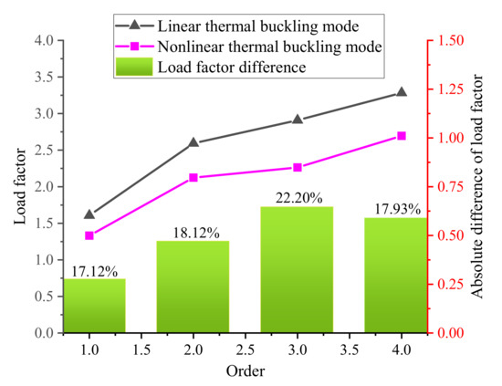
Figure 16.
The load factors of two kinds of thermal buckling.
Hence, the results of linear buckling are often used as critical reference values, while nonlinear buckling is more suitable for accurate results. Compared with the conclusions in Ref. [15], under thermal shock load, obvious torsional deformation and large radial deformation of the blade will increase the probability of thermal buckling instability, resulting in an important impact on the rub-impact response of blade-casing structure.
5. Conclusions
Based on the thin-walled buckling theory and FEM, the linear and nonlinear thermal buckling characteristics of thin-walled blades were compared in this paper. By fitting the actual blade temperature distribution, an effective method for load buckling thermal analysis is deducted and applied. Through theoretical and simulation analysis, its deformation characteristics and stress distribution were also calculated, and the critical buckling load determined the upper limit of theoretical buckling strength for the restrained blade.
Using linear buckling results, the effects of initial imperfections and large deformations were introduced to effectively simulate the nonlinear buckling characteristics of blades. In terms of the non-linear buckling analysis, the modal deformation mainly presented as the overall warpage, and the maximum torsional deformation was up to 1.424 mm. Moreover, the maximum deformation along the radial and axial directions exceeded 1 mm and the largest stress reached to 80 MPa. In addition, the comparative analysis of critical load factors also proves the instability state of the blade. The critical load factors became larger with the modal order increase from 1.6067 to 3.28331 of linear bucking, and from 3316 to 2.6947 of nonlinear bucking.
It was demonstrated that the linear and nonlinear buckling modes and stress distributions were different, especially in the shape of blade deformation and the position where the maximum deformation occurred. Furthermore, the obtained results are expected to guide the feasible and optimized design of thin-walled blades, which will be an important way to reduce rub-impact accidents.
Author Contributions
Conceptualization, X.M.; methodology, X.M.; software, X.M.; validation, Y.P.; temperature distribution, Y.P.; investigation, Z.J.; data curation, T.Z.; formal analysis and software, H.Z.; writing—review and editing, X.M. and X.F.; supervision, Y.P.; project administration, X.M., Y.P. and X.F.; funding acquisition, X.M., Y.P. and X.F. All authors have read and agreed to the published version of the manuscript.
Funding
This research was funded by the general project of Shandong Natural Science Foundation (ZR2021ME179, ZR2021ME183), key projects of Shandong Natural Science Foundation (ZR2020KE022), and the Jinan scientific research leader studio project (2019GXRC054).
Institutional Review Board Statement
Not applicable.
Informed Consent Statement
Not applicable.
Data Availability Statement
There are no relevant statements for this research.
Acknowledgments
Thanks to all the participants who promoted the successful completion of this article, which was funded by the general project of Shandong Natural Science Foundation (ZR2021ME179, ZR2021ME183), key projects of Shandong Natural Science Foundation (ZR2020KE022), and the Jinan scientific research leader studio project (2019GXRC054).
Conflicts of Interest
The authors declare no conflict of interest.
References
- Men, X.H.; Zhang, T.Y.; Pan, Y.Z. Investigation on linear and nonlinear thermal buckling mode for high-speed thin-walled blade. In Proceedings of the 12th IEEE Global Reliability & Prognostics and Health Management Conference, Nanjing, China, 15–17 October 2021. [Google Scholar]
- Sahraei, A.; Mohareb, M. Lateral torsional buckling analysis of moment resisting plane frames. Thin-Walled Struct. 2018, 134, 233–254. [Google Scholar] [CrossRef]
- Li, P.; Xu, Y.T. Effect of boundary condition on dynamic response during thermal–Acoustic test. J. Vib. Eng. Technol. 2019, 7, 33–42. [Google Scholar] [CrossRef]
- Yang, Y.; Wu, C.W. Coupling analysis for the thermo-acoustic-vibration response of a thin-walled box with acoustic excitations. J. Vib. Eng. Technol. 2016, 4, 423–429. [Google Scholar]
- Abir, D.; Nardo, S.V. Thermal buckling of circular cylindrical shells under circumferential temperature gradients. J. Aerosp. Sci. 2012, 26, 803–808. [Google Scholar] [CrossRef]
- Sabzikar, B.M.; Slami, M.R. Thermal buckling of piezo-FGM shallow spherical shells. Meccanica 2013, 48, 887–899. [Google Scholar] [CrossRef]
- Anh, V.T.T.; Bich, D.H.; Duc, N.D. Nonlinear stability analysis of thin FGM annular spherical shells on elastic foundations under external pressure and thermal loads. Eur. J. Mech.—A/Solids 2014, 50, 28–38. [Google Scholar] [CrossRef]
- Gao, J.H.; Liu, S.G.; Feng, X.N.; Heng, J. Theoretical investigation of local buckling of plate-shell structures at elevated temperatures. Tuijin Jishu/J. Propuls. Technol. 2015, 36, 285–291. [Google Scholar]
- Wang, Y.L. Nonlinear random responses and fatigue prediction of elastically restrained laminated composite panels in thermo-acoustic environments. Compos. Struct. 2019, 229, 111391. [Google Scholar] [CrossRef]
- Zhao, T.Y.; Yuan, H.Q.; Li, B.B.; Li, Z.J.; Liu, L.M. Analytical solution for rotational rubbing plate under thermal shock. Appl. Math. Model. 2021, 89, 268–284. [Google Scholar]
- Chang, T.; Dai, T. Analysis of thermal buckling and secondary instability of post-buckled S-FGM plates with porosities based on a meshfree method. Compos. Struct. 2004, 64, 211–218. [Google Scholar]
- Liu, L.; Li, J.M.; Kardomateas, G.A. Nonlinear vibration of a composite plate to harmonic excitation with initial geometric imperfection in thermal environments. Compos. Struct 2019, 209, 401–423. [Google Scholar] [CrossRef]
- Spottswood, S.M.; Hollkamp, J.J.; Eason, T.G. Reduced-Order models for a shallow curved beam under combined loading. AIAA J. 2010, 48, 47–55. [Google Scholar] [CrossRef]
- Yu, T.T. Buckling isogeometric analysis of functionally graded plates under combined thermal and mechanical loads. Compos. Struct. 2017, 162, 54–69. [Google Scholar] [CrossRef]
- Yu, T.T. NURBS-based isogeometric analysis of buckling and free vibration problems for laminated composites plates with complicated cutouts using a new simple FSDT theory and level set method. Thin-Walled Struct. 2016, 101, 141–156. [Google Scholar] [CrossRef]
- Kabir, M.Z.; Tehrani, B.T. Closed-form solution for thermal, mechanical, and thermo-mechanical buckling and post-buckling of sma composite plates. Compos. Struct. 2017, 168, 535–548. [Google Scholar] [CrossRef]
- Golmakani, M.E.; Moravej, M. Dynamic relaxation method for nonlinear buckling analysis of moderately thick FG cylindrical panels with various boundary conditions. J. Mech. Sci. Technol. 2016, 30, 5565–5575. [Google Scholar] [CrossRef]
- Chen, R.X.; Mei, C. Finite element nonlinear random response of beams to acoustic and thermal loads applied simultaneously. In Proceedings of the 34th Structures, Structural Dynamics and Materials Conference, La Jolla, CA, USA, 19–22 April 1993. [Google Scholar]
- Kamarian, S.; Shakeri, M. Thermal buckling analysis and stacking sequence optimization of rectangular and skew shape memory alloy hybrid composite plates. Compos. Part B Eng. 2017, 116, 137–152. [Google Scholar] [CrossRef]
- Kandasamy, R.; Dimitri, R.; Tornabene, F. Numerical study on the free vibration and thermal buckling behavior of moderately thick functionally graded structures in thermal environments. Compos. Struct. 2016, 157, 207–221. [Google Scholar] [CrossRef]
- Sha, Y.D.; Wang, J. Vibration responses analysis and experimental verification of metallic thin-walled structures to thermal-acoustic loadings. Chin. J. Aeronaut. 2017, 30, 1919–1930. [Google Scholar] [CrossRef]
- Reddy, J.N. Nonlocal theories for bending, buckling and vibration of beams. Int. J. Eng. Sci. 2007, 45, 288–307. [Google Scholar] [CrossRef]
- Wu, D.F.; Wang, Y.W.; Shang, L.; Pu, Y.; Wang, H.T. Test research and numerical simulation on thermal modal of plate structure in 1200 °C high-temperature environments. Acta Aeronaut. Astronaut. Sin. 2016, 37, 1861–1875. [Google Scholar]
- Wang, G.F.; Feng, X.Q. Timoshenko beam model for buckling and vibration of nanowires with surface effects. J. Phys. D Appl. Phys. 2009, 42, 155411. [Google Scholar] [CrossRef]
- Zhao, Y.; Hua, Y.X.; Zhang, Z.N.; Chai, X.H. A new blade-casing rubbing modal based on hertz contact theory. J. Shanghai Jiao Tong Univ. 2019, 53, 660–664. [Google Scholar]
- Sha, Y.D.; Bai, W.J.; Zhao, F.T. Analysis of nonlinear vibration response characteristic of thermal buckling carbon/Silicon Carbide (C/SiC) Thin-walled Structure under Thermal-acoustic Loadings. Sci. Technol. Eng. 2016, 16, 109–115. [Google Scholar]
- Cheng, X.S. Thermal bending of Rectangular Thin Plate with two opposite edges clamped, one edge simply supported and one edge free. KSCE J. Civ. Eng. 2016, 20, 333–342. [Google Scholar] [CrossRef]
- Przekop, A.; Rizzi, S.A. Dynamic snap-through response of thin-walled structures by a reduced order method. AIAA J. 2006, 45, 68–75. [Google Scholar]
- Liu, W.; Su, X.Y.; An, Y.R.; Huang, K.F. Local buckling prediction for large wind turbine blades. Tech. Sci. Press 2011, 25, 177–193. [Google Scholar]
- Li, C.W.; Li, H.Y.; Wang, C.; Zhang, Z.P.; Sun, Q. A study of influencing factors on frequencies and mode shapes of aeroengine turbine blades. J. Air Force Eng. Univ. (Nat. Sci. Ed.) 2014, 15, 5–9. [Google Scholar]
- Ai, S.M. Study of Effects of Temperature Field on Aero engine Rotor System Dynamic Characteristics. Master’s thesis, Shen Yang Aerospace University, Shenyang, China, 2012. [Google Scholar]
- Sushila, R.; Agrawal, A.K.; Rastogi, V. Failure analysis of a first stage IN738 gas turbine blade tip cracking in a thermal power plant. Case Stud. Eng. Fail. Anal. 2017, 26, 1–10. [Google Scholar]
Publisher’s Note: MDPI stays neutral with regard to jurisdictional claims in published maps and institutional affiliations. |
© 2022 by the authors. Licensee MDPI, Basel, Switzerland. This article is an open access article distributed under the terms and conditions of the Creative Commons Attribution (CC BY) license (https://creativecommons.org/licenses/by/4.0/).