Article

Numerical Performance Investigation of a Hybrid eCVT Specialized Agricultural Tractor

by
Francesco Mocera
*,† and
Valerio Martini
Department of Mechanical and Aerospace Engineering, Politecnico di Torino, Corso Duca degli Abruzzi 24, 10129 Torino, Italy
*
Author to whom correspondence should be addressed.
These authors contributed equally to this work.
Appl. Sci. 2022, 12(5), 2438; https://doi.org/10.3390/app12052438
Submission received: 27 January 2022 / Revised: 22 February 2022 / Accepted: 24 February 2022 / Published: 25 February 2022
(This article belongs to the Special Issue Frontiers in Hybrid Vehicles Powertrain)

Abstract

:
The need for highly efficient agricultural machineries is increasing the interest of the research community and of industrial manufacturers towards the use of integrated electric systems in combination with traditional powertrain elements. In this work, a hybrid electric tractor with electric continuously variable transmission (eCVT) capabilities was studied to investigate their performance in comparison with that of traditional diesel-powered tractor designs. This hybrid electric configuration can be classified as a power-split architecture that aims to combine the best characteristics of both the simpler parallel and the series hybrid layout while minimizing their main drawbacks. An eCVT configuration can allow for optimizing the diesel operating point with respect to the current working conditions, and achieving peak power performance and energy saving with relatively small electric machines. The proposed hybrid eCVT (HeCVT) tractor architecture was studied using a numerical model that allowed for developing two different control strategies: a charge depleting mode enabling the driver to use full power for the most power-intensive scenarios and a charge sustaining mode developed to optimize efficiency and battery use along an entire work day. To test the proposed architecture, several tasks derived from experimental field measurements on a specialized agricultural tractor were used. HeCVT results were compared with a numerical model of the traditional tractor validated by these experimental data. The HeCVT tractor showed good performance in terms of peak power capabilities using a downsized diesel engine, and consistent fuel savings were obtained according to typical daily working scenarios.

1. Introduction

The growing need for food to sustain population growth requires a high level of productivity from the agricultural field, which is responsible for raw material supply. To maintain the rhythm with the entire chain, agricultural mechanization plays a crucial role in increasing farm productivity [1]. However, everything comes with a price. It is estimated that only the agricultural field is responsible for almost 20% of the annual global production of CO2 emissions [2]. In particular, self-propelled agricultural machineries are responsible for the production of CO2, CO, NOx, particulate matter (PM), and hydrocarbons (HC) as side products deriving from fuel combustion within their diesel engines [3,4]. These machines are characterized by medium–high power demand and may need to run for 8–12 h per day in certain periods of the year to meet harvesting schedules. To mitigate their impact on pollutant emissions, strict regulations are progressively introduced [5] providing specifications for diesel engines emissions for all non-road mobile machineries (NRMMs) as a function of the power rating of their engines. OEM diesel engine manufacturers have focused their efforts on the development of exhaust gas aftertreatment systems [4] as a solution to comply with emissions regulations. As a matter of fact, not being able to meet those limit values would prevent their customers from sell their machines. However, those systems require increasingly more dedicated space with the increasing level of restrictions. Aftertreatment systems both do not solve the emissions problem due to side products they produce, and have introduced an increasing level of complexity when it comes to vehicle integration of such devices. Agricultural, in particular specialized, tractors, are well-known for the compactness of their powertrain, which helps in improving stability, visibility, and manoeuvrability. This is the reason why researchers and manufacturers involved in the agricultural field are investing time and money to explore new technologies to reduce emissions production, improving the overall machine efficiency for a given working task.
Thanks to the achievements in the transportation field, electrification is now one of the most promising strategy to improve machine efficiency in agricultural applications [6,7,8]. Electrification of an agricultural powertrain can take place at different levels depending on the specific use. Somà et al. [9] proposed a Hybridization Factor (HF) for NRMMs with the aim of defining the correct weight between the thermal engine and the electric machines in the powertrain. The authors suggest that the HF should derive from the knowledge of the work cycles the machines are expected to accomplish [10]. Although several attempts from different associations and companies [11], today the lack of standard work cycles forces researchers and manufacturers to the adoption of an experience-based design approach related to statistical features of historical and experimental data [12]. For some machines, a good understanding of the daily work cycle can bring to full electric (FE) architectures [13] where the internal combustion engine can be totally replaced by a battery-pack-based storage system, achieving an HF = 1. This, with the use of green technology for clean electricity [14], would achieve zero emissions at least in the use phase of agricultural machines’ life cycle. However, in most cases, knowledge of the work cycle is not so straightforward because of the multi-purpose nature of agricultural machinery. This is very typical for agricultural tractors, which can be considered to be mobile propulsion systems to propel externally attached implements and tools [15]. Full electric tractors (FETs) are explored in the literature for small-medium sized machines. Liu et al. [16] proposed an FET powered by a low-voltage battery pack for small-farm low-power applications. Li et al. [17] proposed optimizing a dual-motor FET architecture to improve overall efficiency. In this case, the authors also considered a small–medium sized power tractor as reference for their analysis. The main reason was related to the objective difficulty in the design of a proper battery pack in heavy work-vehicle applications in terms of the trade-off in performance [18] and costs [19].
As shown in [6,20], hybrid electric tractors (HETs) represent the most feasible solution for medium-high size machines in the upcoming decade. Dalboni et al. [21] proposed an HET with parallel architecture powered by a downsized diesel engine and a 25 kWh battery pack. The authors numerically investigated the architecture against several field working scenarios with a charge-sustaining energy management strategy showing promising fuel savings. A similar parallel architecture was investigated by Mocera et al. [22,23], testing the HET model against test cases derived from field measurements on a traditional diesel-powered orchard tractor. The authors demonstrated that the proposed architecture was able to perform as well as the traditional tractor in terms of peak performance despite the downsized diesel engine, and to achieve 18% fuel saving in daily working cycles on average thanks to the proposed load observer strategy. Baek et al. [24] proposed a HET with series configuration with four dedicated wheel motors receiving power from both the battery pack and the four gasoline engine-based commercial generators. However, the range extender configuration of the architecture, a limited range of 2.5 h, was estimated for heavy plough tillage and 6 h for low-speed drive. Jia et al. [25,26] proposed a numerical investigation to optimize the use of a series architecture for agricultural tractors. Using dynamic programming to approach optimal control, the authors were able to improve fuel efficiency by about 5% with respect to results of the same architecture managed with rule-based strategies. Parallel and series configurations have advantages and disadvantages. Parallel HETs are the most promising configurations because of their relatively easy implementation on existing vehicles. However, the main limitation of parallel configuration is the mechanical coupling between ICE and mechanical load (wheels and power take off (PTO)), which prevents it from achieving the best results in terms of efficiency and emissions optimization. These problems would be solved in a series HET configuration that would instead require large electric machines to have full power on both PTO and drivetrain. This is the reason why the combined power-split configuration was recently investigated in the literature for agricultural tractors. Rossi et al. [27] explored a hybrid eCVT (HeCVT)-based tractor architecture for performance evaluation. The proposed layout consisted of an eCVT transmission inspired by the Toyota Prius layout for the driveline [28] and a direct connection of the sun gear/ICE to the PTO allowing for direct power path from ICE to attached implement. The authors defined three different operating modes for this powertrain architecture: full hybrid mode to approach full speed and heavy load; parallel hybrid mode for heavy load at low-medium speed; and EV mode for low-power application. Despite the higher complexity of the architecture and its control algorithm, the power-split configuration allowed for the engine to work at the optimal rotational speed for a given instantaneous load but at the same time gave the possibility of a joint cooperation in parallel with the electric system when needed. This is crucial to keep electric motors small and in compliance with space requirements for agricultural tractors. Tebaldi et al. [29] proposed investigating a similar eCVT powertrain applied on an agricultural tool, demonstrating ICE efficiency improvements thanks to the degree of freedom introduced with the use of the power-split configuration.
In this work, an alternative hybrid eCVT (HeCVT) configuration, such as the one proposed in [30], was investigated, and its performance was compared to that of a traditional specialized orchard tractor. The proposed numerical model was used to test the architectural characteristics according to several testing scenarios proposed by the authors in previous works [22,23], derived from experimental field tests. Two energy management strategies were defined to meet the need for daily working scenarios [31]. Thanks to the energy management strategy proposed by the authors in this paper, the HeCVT architecture for specialized orchard tractor under investigation was able to achieve the following results:
  • Peak power performance comparable with those of a conventional tractor but with a downsized diesel engine and a simplified gearbox. The last point is not something that was considered in other works that wanted to keep the same tractor gearbox.
  • Increased overall efficiency with fuel saving ranging from 10% in the most heavy PTO loading scenarios up to 20% in heavy trailer transportation.
  • Capability for full electric operations decoupling the ICE and using the two electric machines in a dual-input-motor configuration using the energy stored in the battery pack.

2. Case Study

In this work, analysis focused on an a specialized orchard tractor, a category where compactness is crucial. These vehicles must be able to work nimbly among narrow rows and to have good curving capabilities to increase productivity. Table 1 shows the relevant characteristics of the conventional diesel-powered orchard tractor considered for this analysis.
Traditionally, these working vehicles adopt high-power diesel units to cover the widest possible range of applied loads. However, considering the most common working scenarios for these tractors, their powertrains usually work at medium–low loads far from the optimal efficiency condition, leading to unnecessary fuel consumption. In order to simulate the behavior of the conventional tractor, its main subsystems were numerically modelled with MATLAB/Simulink using a modular and multiphysics power-based approach described in previous works [22]. The main subsystems covered in this work were:
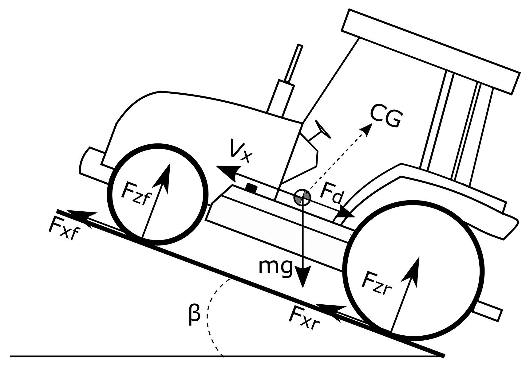
  • vehicle and trailer dynamics;
  • engine;
  • gearbox and clutches;
  • PTO loads.
The longitudinal dynamic behaviour of the tractor was modelled using a 1D model as shown in Figure 1.
Figure 1. 1D longitudinal tractor model.
Applsci 12 02438 g001
m V x ˙ = 2 F x f + F x r F d m g · s i n β
F z f = h F d + m g · s i n β + b · m g · c o s β 2 ( a + b )
F z r = + h F d + m g · s i n β + a · m g · c o s β 2 ( a + b )
where:
  • a, b, and h represent the relative position of the centre of gravity of the vehicle with respect to the front and rear axles;
  • m is the tractor mass; g the acceleration of gravity;
  • β is the road slope angle;
  • V x is the vehicle longitudinal speed;
  • F d is the aerodynamic drag force as
    F d = 0.5 ρ C d A V x 2 · s i g n ( V x ) ,
    ρ , air density; and C d , drag coefficient, a frontal cross-sectional area of the vehicle. However, this contribution is almost negligible for this specific application.
  • F x f and F x r are contact forces between wheels and ground on the longitudinal direction (front and rear axle).
  • F z f and F z r are normal contact forces between wheels and ground (front and rear axle).
When modelling the presence of a trailer attached to the tractor, the connection between them was considered to be rigid. As a consequence, they shared the same longitudinal speed. During simulations, different payloads were considered for the trailer by changing its body mass. The engine’s power output, as a combination of torque and speed, was numerically modelled using a tabulated torque data approach. Figure 2 shows the torque and power curves of the thermal unit considered in this work for the conventional powertrain. The proposed torque and power curves were derived from data available online for commercial diesel-engine units having nominal characteristics as close as possible to the ones of the reference conventional tractor studied in this and previous works by the authors.
In order to compare the traditional powertrain and the proposed hybrid architecture, the engine subsystem included a multiparameter fuel consumption model that could consider both the ICE operating point characteristics and its nominal power rating. This model was developed by the Nebraska Tractor Test Laboratory and proposed by Grisso et al. [32]. This model was derived from fuel consumption measurements by the previously mentioned laboratory on more than 500 diesel engines designed for tractors. Although it gives an approximation for fuel consumption, it was considered to be sufficient since the main purpose of this work is not to evaluate the real fuel consumptions, but to make a comparison between the fuel consumptions of the conventional powertrain and the proposed hybrid architecture when facing the same tasks. This model was chosen since it correlated the rated power of the engine and its fuel consumption. The model consisted of the following equations:
Q F = ( 0.0434 · X + 0.019 ) · P n o m
Q R = Q F · 1 ( N 1 ) · ( 0.45 · X + 0.877 )
where:
  • Q F is diesel fuel consumption at partial load and full throttle (gal/h);
  • Q R is diesel fuel consumption at partial load and reduced throttle (gal/h);
  • X is the actual engine load expressed as the ratio of the actual engine output power over the maximal power available at the same speed (-);
  • P n o m is the nominal engine power (hp);
  • N is the ratio between actual engine speed and nominal speed at which P n o m is evaluated.
In the gearbox, tractors usually have a high number of transmission ratios. The conventional powertrain considered in this work had a total number of 32 possible gear ratios (Figure 3): two speed ranges (low–high) with four gears, a gear pair for further reduction of all previous combinations (creeper gear), a reverse gear to allow for the use of all 16 gear ratios in backward and forward motion. This complex gearbox architecture is not uncommon in agricultural tractors and allows for having engine power available as much as possible, from very-low-speed field operations up to their max speed for road transportation. The gearbox in this work was modelled using groups of simple gears connected in series or in parallel with the help of disengaging friction clutches to achieve the overall desired vehicle speed. Lastly, PTO loads representing the power required by the implements connected to the tractor were modelled through a resistive torque applied to the tractor PTO. The powers required by the implements were obtained in previous experimental field tests (Mocera et al. [22]) with the angular speed of the PTO fixed at 540 rpm. Table 2 shows a summary of these three working scenarios.

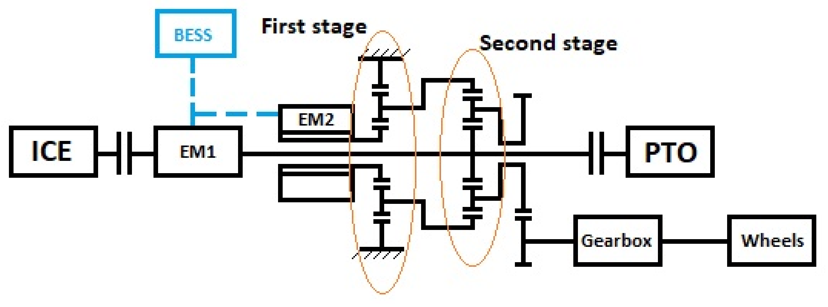
3. Hybrid eCVT Powetrain

3.1. Architecture and Components

The proposed hybrid architecture consisted of a downsized thermal unit and two reversible electric machines. The main component of the transmission was a two-stage planetary gear that allowed for achieving a power-split hybrid configuration, and thereby electronic continuously variable transmission (eCVT). In detail, the ICE was mechanically connected through a clutch to the first electric machine (EM1). The drive shaft was also linked to the sun gear of the second planetary gear stage and, with a clutch, to the power take off (PTO). The rotor of the second electric machine (EM2) was mechanically connected to the sun gear of the first planetary gear stage, whose ring gear was fixed to the chassis. The carrier of this first stage was connected to the crown of the second planetary gear stage. Finally, the carrier of the second stage was connected to the drive shaft of a two speed gearbox which output were the rear and front axles differentials. Figure 4 shows the proposed powertrain layout. This configuration allowed for having no direct connection between ICE and wheels. However, with a proper control, it could allow for the joint cooperation with the electric machines to have full power at different vehicle speed levels. Through the disengagement of the clutch between ICE and EM1, the powertrain was able to operate in full electric mode using the two electric machines together for the best use of the electric energy stored in the battery pack. Lastly, the position of EM2 in this architecture enabled regenerative braking, although the impact was negligible if not for very special work scenarios.
The use of a downsized ICE for this HeCVT tractor was motivated by the following considerations:
  • Specialized tractors are usually equipped with high power diesel engines but, for a large part of their operative life, they work at medium–low load, which translates into suboptimal overall efficiency, and thus excessive fuel consumption. Instead, a downsized ICE working at higher percentage loads that are closer to the nominal design value can achieve better fuel efficiency.
  • Tractors’ emission limits are imposed by the NRMM regulation, which classifies engines according to their application and nominal rated power. The larger the engine, the higher the pollutant production per unit of work. Therefore, an oversized diesel engine has stricter restrictions about the pollutants that it is allowed to produce; thus, it would require large volumes for exhaust gas aftertreatment systems. This is not compatible with compact specialized tractors.
The power and torque curves of the downsized engine considered for the HeCVT tractor are shown in Figure 5. In this case, the proposed torque and power curves were also derived from data available online for commercial diesel engine units having nominal characteristics as close as possible to the desired ones.
The properties of the two electric machines are reported in Table 3. The numerical model of the EMs defines electrical losses as the sum of the following terms: fixed converter losses, ohmic losses (torque-dependent), and iron losses (speed-dependent) due to eddy currents. In some difficult situations, electric machines can count on a temporary boost function. It consisted of an increase in available torque due to the use of a higher level of current. However, this capability had the following constraints to preserve motor functionalities:
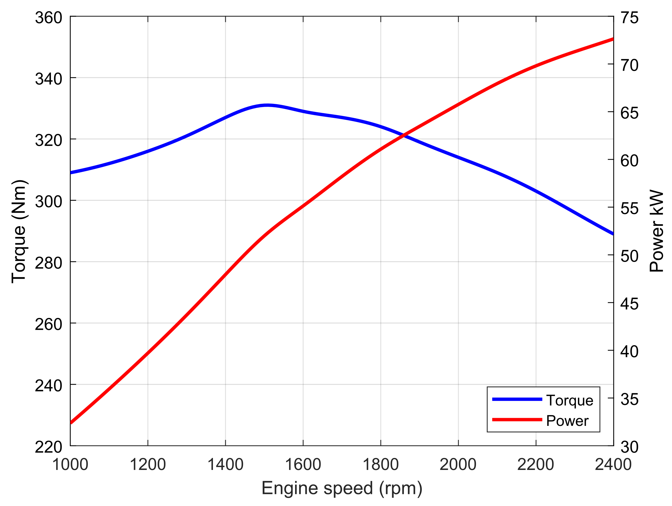
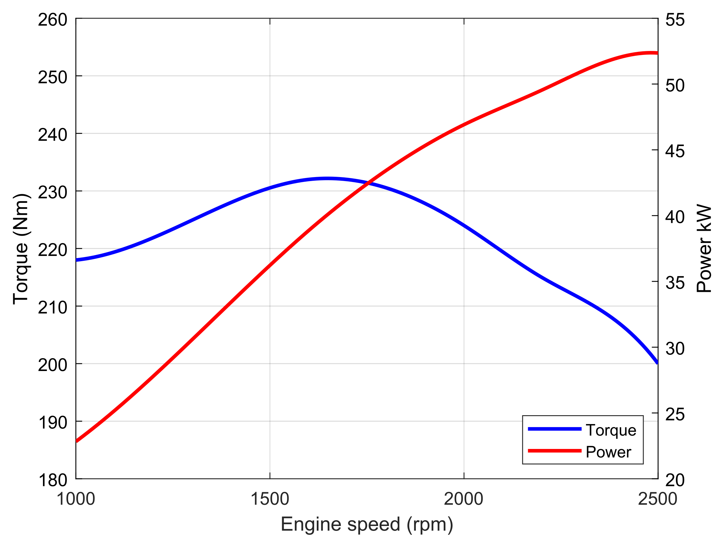
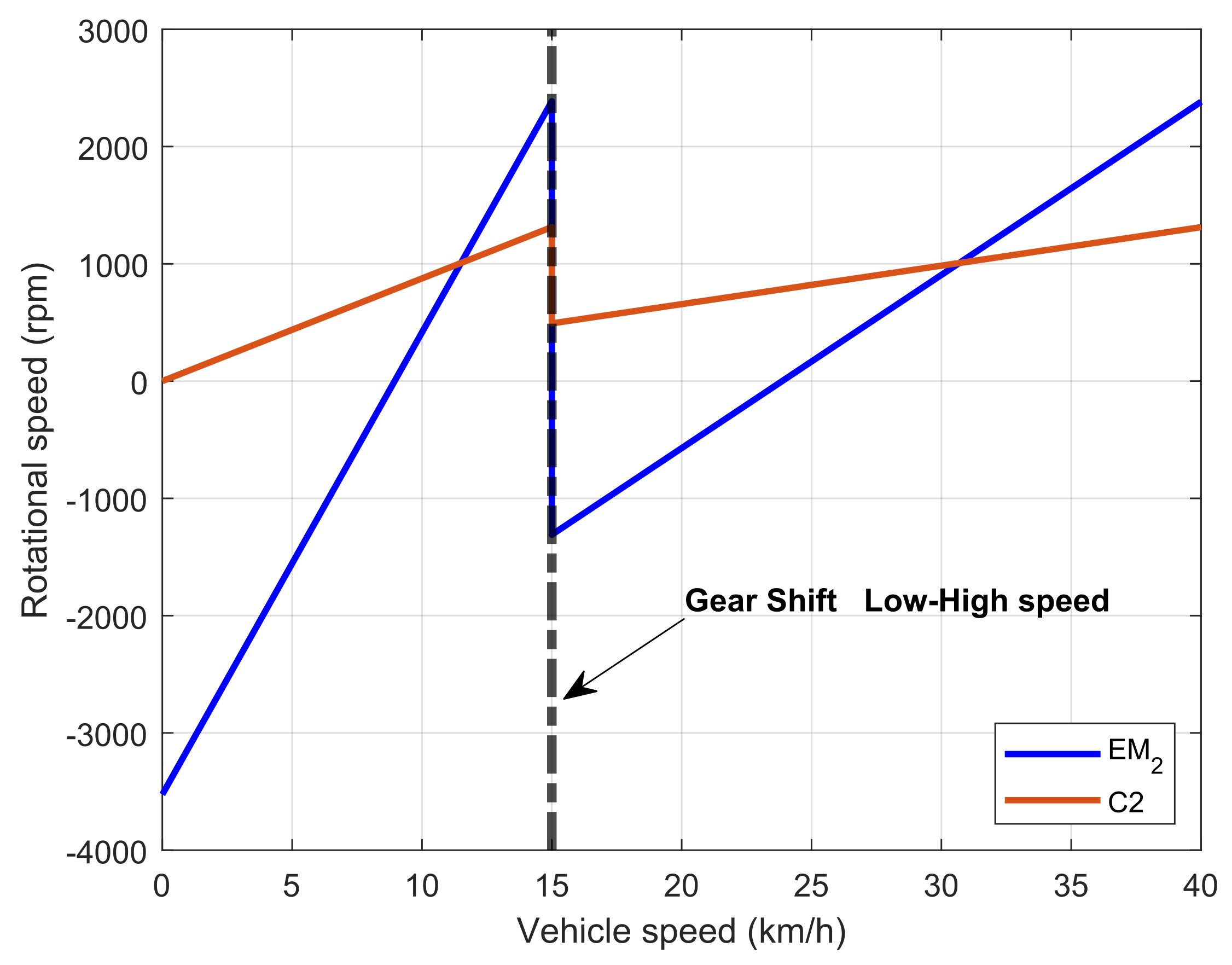
  • at low speed below 1100 rpm, torque could be amplified up to twice the nominal value;
  • above 1100 rpm, torque amplification should be limited by the rated power value for the machine.
Table 3. Main properties of proposed electric units.
EM1 nominal power35 kW
EM1 maximal torque145 Nm
EM1 nominal efficiency93%
EM2 nominal power30 kW
EM2 maximal torque130 Nm
EM2 nominal efficiency93%
The main purpose of EM2 was to control the vehicle speed, while the EM1:
  • helps the ICE in providing power to the PTO;
  • is turned by the ICE in order to provide electric power to EM2 for an electric power split;
  • recirculates power when EM2 acts as a brake for low vehicle speed, helping the ICE in parallel.
As mentioned before, the two-stage planetary gear allowed for considering a simplified two-speed gearbox with only two speed ranges to increase torque availability at low vehicle speed. The gear ratios were chosen so that the base speed of EM2 reached approximately 15 km/h in a low-speed regime, and 40 km/h in a high-speed regime, with the ICE rotating at 2350 rpm. Table 4 shows the transmission ratios of the driveline.
Along with the electric machines and drives, an energy storage system consisting of a battery pack (BP) was introduced. To meet the typical compactness needs of specialized orchard tractors, the sizing of the BP capacity was chosen as a compromise between fuel consumption optimization and required volume. As in previous work [22], the proposed BP in this work had a nominal voltage of 600 V and a nominal capacity of 16 kWh. To meet the needs for a compact battery pack, lithium-ion technology was considered because of the higher energy density with respect to other chemistries available on the market. From a numerical point of view, the BP was modelled with an equivalent circuit model consisting of a voltage source and an internal resistance. The instantaneous electric power provided by the BESS was evaluated considering the power required by the EMs in accordance with a physical network (PN) modelling approach. The PN is a modular modelling approach where each element is considered to be a physical entity capable of exchanging energy with all the other subsystems to which it is connected, with the constraint that the solutions of the system must satisfy the power balance equations for each component. To evaluate the actual state of charge of the battery pack, the authors opted for a simple Coulomb counting strategy, neglecting more detailed models available in the literature. The following equations were used.
C u s e d = t 1 t 2 i b a t t d t
S O C = C n o m C u s e d C n o m
where:
  • C u s e d is the used capacity;
  • C n o m is the nominal capacity;
  • S O C is the state of charge of the battery pack.

3.2. Hybrid eCVT Control

3.2.1. Kinematics

In order to properly control the powertrain, kinematic relations between different components and wheels must be explored. The notation used in the equations was based on the following principles:
  • Subscripts S, C and R refer to sun, carrier, and ring gears, respectively.
  • Subscripts 1 and 2 refer to first- and second-stage planetary gear, respectively.
In accordance to these premises, the following equations could be obtained:
i S R = ω S ω C ω R ω C
If ω R = 0 , it is possible to assert:
i S C = z S + z R z S
Therefore,
ω C 1 = ω S 1 i S C 1 = ω E M 2 1 + z R 1 z S 1 = ω R 2
Regarding the second-stage planetary gear, it is possible to write:
ω C 2 = ω S 2 i S R 2 · ω R 2 1 i S R 2
Since ω S 2 = ω I C E , it is valid that:
ω E M 2 = ω C 2 1 + z R 2 z S 2 ω I C E z S 2 z R 2 1 + z R 1 z S 1
where ω C 2 is kinematically linked to the wheels through the gearbox. Equation (12) enabled to control the EM2 decoupling the rotational speed of the diesel engine from the actual vehicle speed. Figure 6 shows the values of EM2 rotational speed and the second-stage carrier along the vehicle speed range of 0–40 km/h. At 15 km/h, the vehicle changed the speed range from low to high speed. Below a certain threshold speed for each regime, EM2 is required to behave as a brake, while EM1 can be used to recirculate power helping the ICE in this work range. Both electric machines could be used to charge the BP in the case of low SOC and low external load.

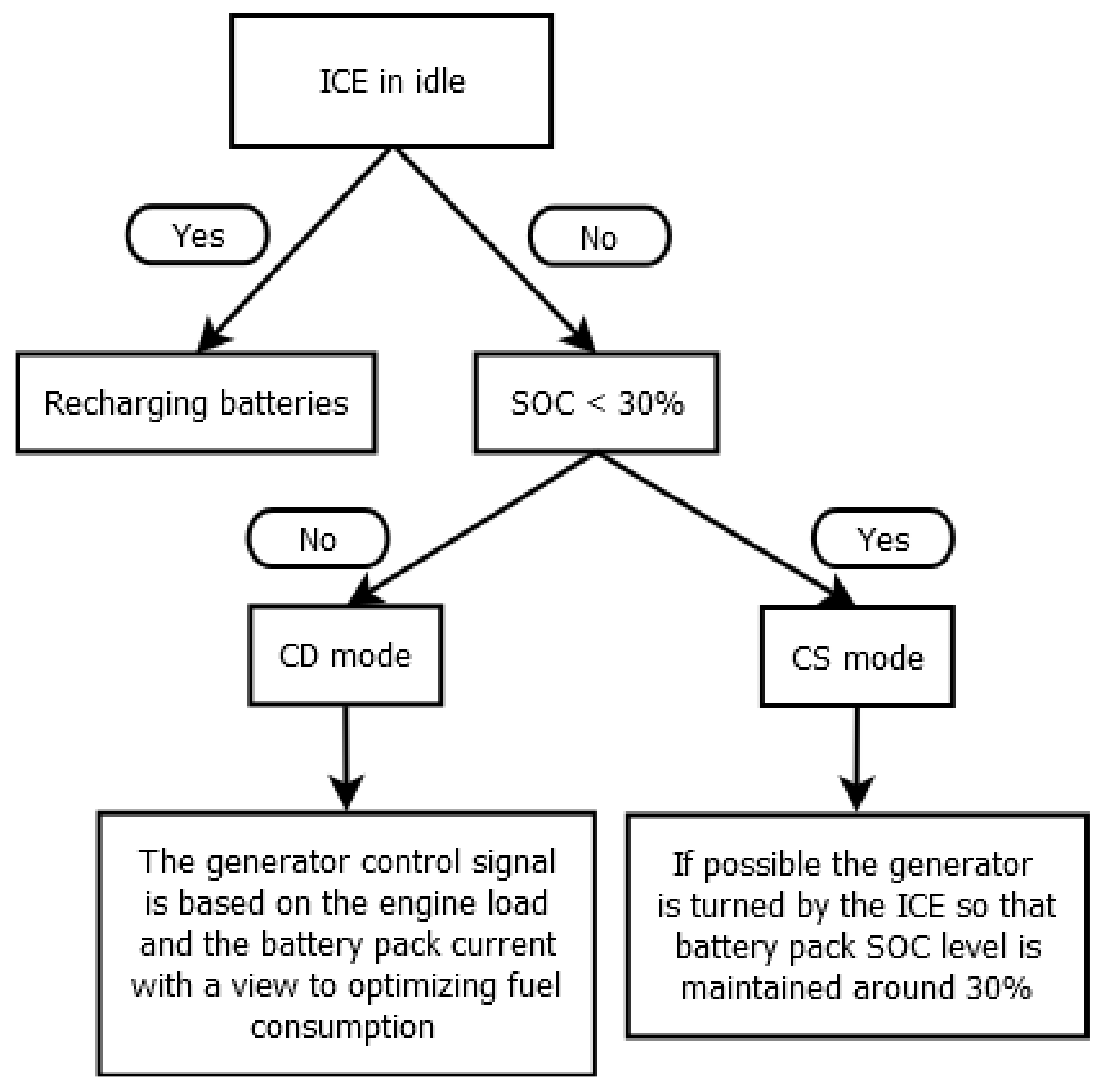
3.2.2. Energy Management

For this preliminary performance analysis, the proposed energy management strategy was based on two operating modes depending on the actual SOC of the battery pack: charge depleting (CD) mode and charge sustaining (CS) mode. When the battery SOC was above a certain threshold value, namely, 30% for this work, the powertrain operated in CD mode, optimizing fuel consumption; below, it operated in CS mode aiming to maintain the current state of charge value. Existing studies suggested that this threshold value should be around 55% to preserve battery life. However, other recent studies that considered a degradation model based on solid electrolyte interphase growth in a Li-ion battery cell showed that the optimal value for the charge sustaining mode is in the range of 36–38%. However, ccording to the same studies, 30% of SOC is a good value for CS mode [31]. In CD mode, the EM1 torque control signal was obtained as the sum of two contributions deriving from the engine actual load and the battery current value. The first contribution was based on a function of the actual engine load (load observer [22]), and it depended on the sign and value of EM2 rotational speed. When EM2 speed was positive, EM1 was mainly actuated for high values of the engine load (load observer), providing additional power to the sun gear drive shaft if necessary; when EM2 speed was negative, acting as a brake or generator, EM1 exploited the recirculation of power deriving from EM2. As a consequence, EM1 helped the ICE with a greater contribution. The second contribution that determined the EM1 torque control signal was calculated as a function of the battery discharge current index, defined as the ratio between battery discharge current and maximal instantaneous acceptable discharge current, fixed at 5C (or five times the BP rated current). This contribution was equal to zero if the system needed to charge the BP. The main goal of the powertrain in CS mode was, if allowed by a low external load, to maintain the SOC level around 30%. When the requested power was too high, the powertrain preferred to accomplish the required task, for example, an occasional peak of power at the PTO and, as soon as possible, it recharged the batteries in order to bring the SOC level back to the threshold value. The EM2 was instead controlled in accordance with the speed requested at the wheels. Lastly, the ICE, since it was not kinematically linked to the vehicle speed, was controlled setting a reference rotational speed depending on the specific work the tractor was tested against. As for regenerative braking, the control system operated using the EM2 to reduce vehicle speed by applying a negative torque. While braking with EM2, EM1 was controlled to maintain its rotational speed and, as a consequence, that of the thermal unit at the reference value. During regenerative braking, the EM2 first acted as a brake, since its angular speed was positive, and it was applying a negative torque. Then, it acted as a motor when its angular speed became negative. In this second case, the recirculation of power came from EM1 acting as a brake to maintain the reference rotational speed constant. During regenerative braking, the torque of the two electric machines was controlled to not exceed the battery pack charge current limit, fixed at 1C. Figure 7 shows a schematic representation of the control strategy of the HeCVT architecture.

4. Numerical Investigation

For a comparison between the conventional powertrain and the proposed HeCVT, numerical simulations focused on performance and fuel consumption. As mentioned before, some constraints regarding maximal discharge and charge current at the battery pack were applied:
  • Maximum battery pack current during continuous discharging equal to 3 C n o m .
  • Maximum battery pack current during instantaneous discharging equal to 5 C n o m (max 10 s).
  • Maximum battery pack current during continuous charging equal to 0.5 C n o m .
  • Maximum battery pack current during instantaneous charging equal to 1 C n o m .
These constraints, derived from previous numerical and experimental activities available in the literature [18], were introduced to consider a hypothetical precautionary approach to preserve the state of health of the BP.

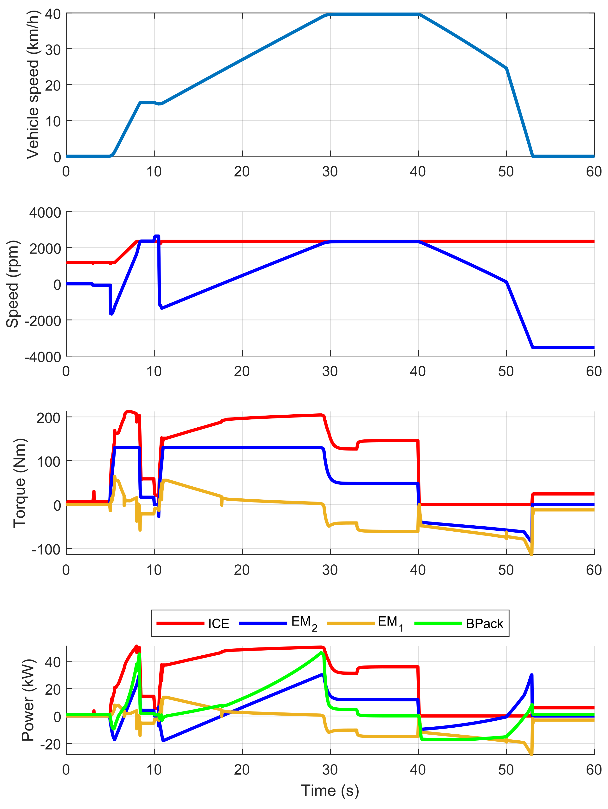
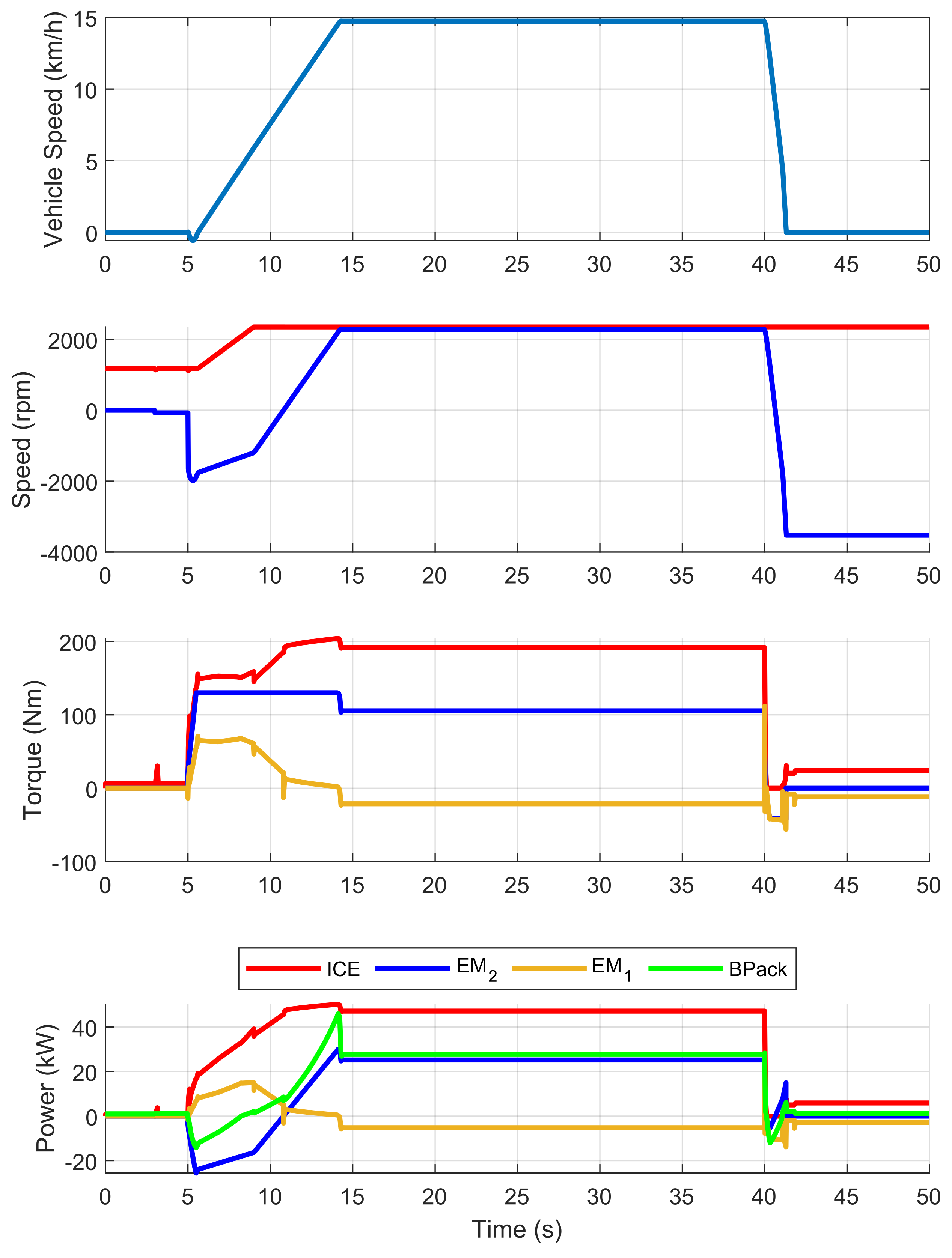
4.1. Acceleration Tests

The proposed acceleration tests aimed to evaluate the performance of the vehicle in the two most representative speed ranges with different payloads on the trailer. Therefore, the following tests were performed:
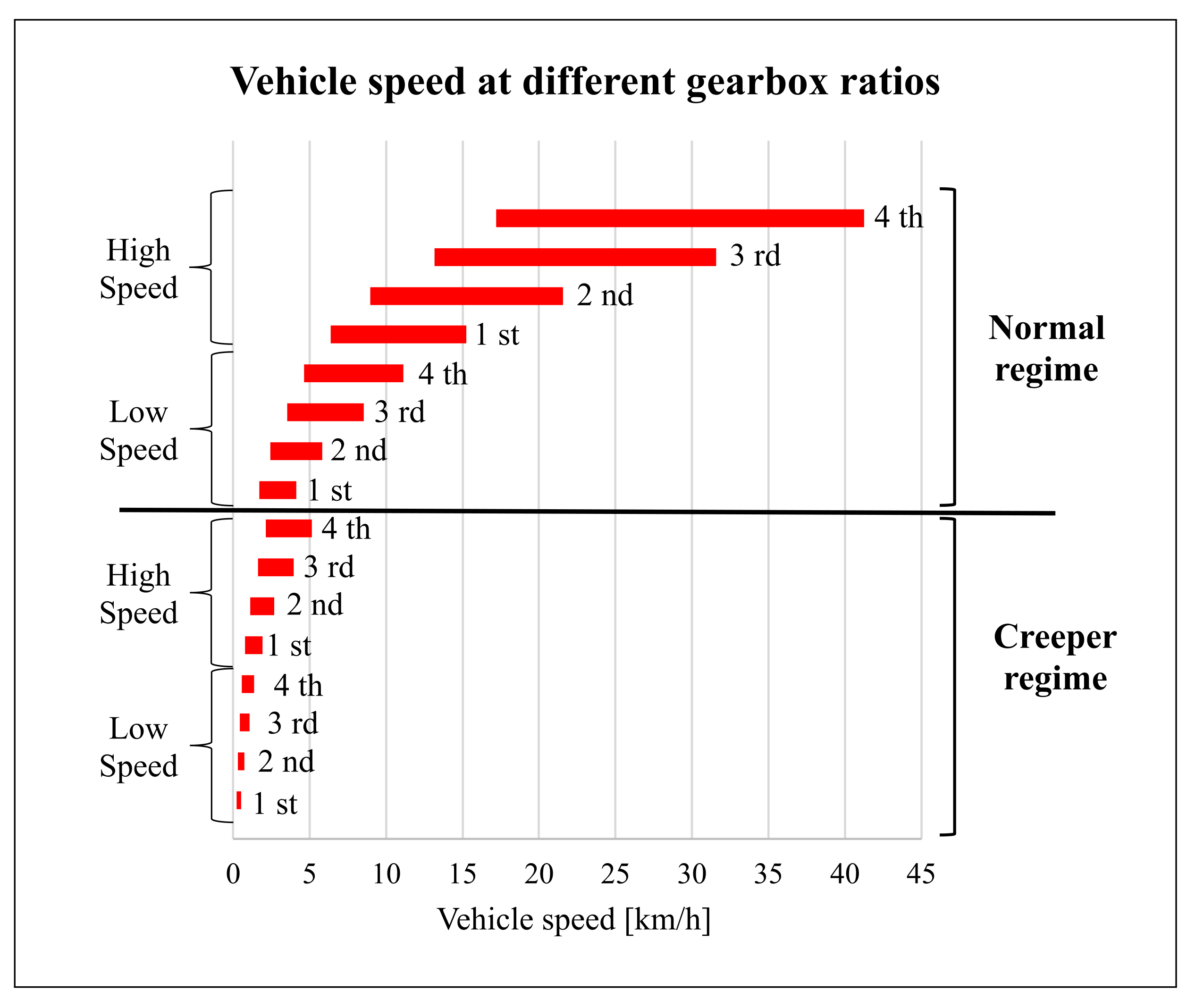
  • 0–15 km/h with no trailer, with a trailer with 6000 kg and 10,000 kg of payloads.
  • 0–40 km/h with no trailer, with a trailer with 6000 kg and 10,000 kg of payloads.
Table 5 shows the results of the acceleration tests, and highlights two different behaviors for the HeCVT in the test performed with a gear shift (GS) between the low and high speed ranges or in the case of a test started directly with the high speed range gear ratios (thus no GS). During the test with GS, the vehicle started in the low-speed regime and changed to a high-speed regime at 15 km/h. This comparison was proposed to show that, if the tractor did not have to pull a heavy trailer, it was possible to use directly the high speed regime without a consistent difference in performance. This would save clutches and other mechanical elements from unnecessary wear and would simplify the driving experience. Results for the conventional powertrain were obtained with gearshifts at 5, 10, and 20 km/h. The conventional powertrain model results were validated by the authors in a previous work using experimental data recorded during tractor field tests in different work scenarios [22,23]. In this work, the HeCVT architecture model was compared with the validated model of the conventional architecture with the same characteristics.
The downsized diesel engine results showed comparable acceleration performance between the HeCVT and conventional tractors. The reason of this was in the possibility of the electric machines, in particular EM2, to cooperate with the ICE through the two-stage planetary gear, providing traction power for the wheels. As an example, Figure 8 shows the simulation results of the 0–40 km/h acceleration test pulling a trailer of 10,000 kg (tare mass + payload). The first diagram shows the vehicle speed, the second the kinematic link between the ICE and the EM2 rotational speed, the third the torque applied by each machine, and the last one their instantaneous power. In this test, it was possible to appreciate the transition from CD mode to CS mode at t = 33 s, when the power generated by EM1 (negative sign) except for conversion losses was directly used by EM2 to maintain the vehicle speed.

4.2. Slope Test

Another important test to evaluate the HeCVT tractor performance in terms of peak power capabilities is the slope test. In this case, different work scenarios were considered to explore different critical work conditions for the powertrain:
  • Maximum approachable slope at 40 km/h with no trailer.
  • Maximum approachable slope at 5 and 15 km/h with 10,000 and 5000 kg of payload, respectively.
  • Maximum reachable speed with no trailer and 45% of slope.
These tests aimed to verify the capability to provide full power at those different speed conditions under the constant load of the road slope. Moreover, each test was performed with a standing start at the prescribed slope to test the tractor capability to also start moving on the proposed slope condition (Italian traffic laws prescribe that the tractor should at least be able to stand start at 14% with the prescribed trailer load). Results are reported in Table 6. In almost all the work conditions, the HeCVT tractor slightly outperformed the conventional one except for the 5 km/h and 10,000 kg trailer test. In that case, the greater number of possible gear configurations given by a traditional gearbox configuration allowed for greater tractive effort at that specific speed, enabling the conventional ICE to work closer to its max power condition. Only in this special work scenario, the HeCVT system required the use of the boost function of the electric system in order to achieve the prescribed slope. The HeCVT tractor recorded good results at 40 and 15 km/h since its two speed regimes were dimensioned for those vehicle speeds.
By way of example, Figure 9 shows the simulations results of the HeCVT architecture 0–15 km/h acceleration test with 5000 kg of payloads and 20% of slope.

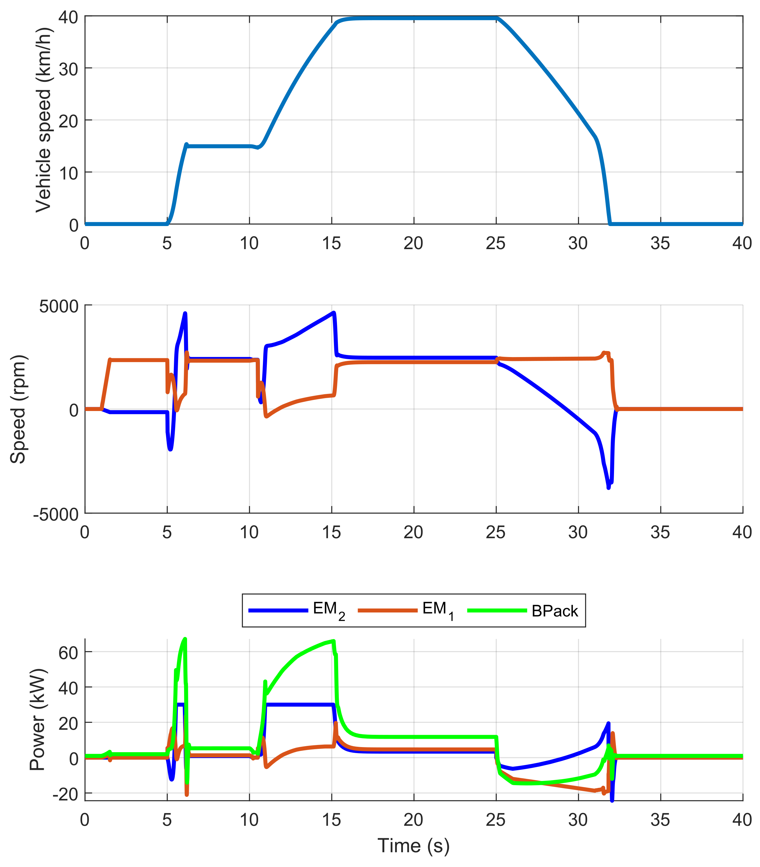
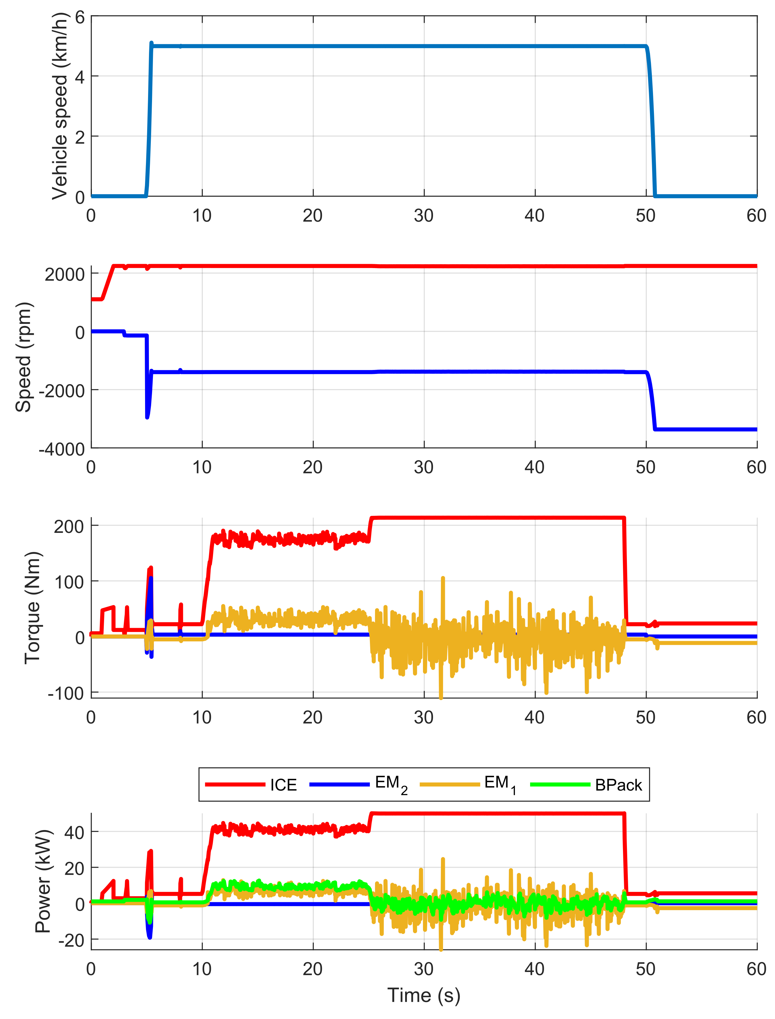
4.3. Work Cycles—Fuel Consumption

In this section, the fuel consumption of the conventional and HeCVT powertrain is compared. Numerical simulations were performed to evaluate the overall energy efficiency of the powertrains during work activities, in particular while pulling trailers and using attached implements powered by the PTO. In particular, the following aspects were investigated:
  • Fuel and energy consumptions per hour in CD mode.
  • Fuel consumption per hour in CS mode.
  • Fuel consumption in proposed working cycles of 8 h.
The main parameters of PTO work activities are described in Table 2. Regarding CD mode, Table 7 shows the energy consumption, defined as the sum of the fuel equivalent energy content and the electric energy used from the battery pack. This value was compared in relative terms to the equivalent energy consumption of the conventional powertrain during the same tasks. For a fair comparison between the conventional and hybrid architecture, the equivalent energy approach was chosen to take into account the use of electric energy in the hybrid powertrain. Given the same mechanical work for the two case studies, the fuel consumption of the diesel engine alone would not be sufficient to demonstrate efficiency improvement because part of the requested energy would be satisfied by the electric reservoir. In this way, both sources were considered together in comparison with the only internal combustion engine of the conventional tractor. The HeCVT architecture recorded great energy saving during the trailer handling thanks to the possibility of optimizing the ICE working point, since the thermal unit was kinematically free from the wheels. Regarding CS mode, Table 7 shows the fuel consumption of the HeCVT architecture compared to the fuel consumption of the conventional powertrain of reference while performing the same tasks.
Lastly, two different types of work cycles were considered: PTO cycles and trailer handling. PTO cycles consisted of an 8 h work day: 90% of the time using the PTO powered implements and 10% of idling for accessory activities, where the tractor is left on to maintain the machine ready to be used. The trailer handling cycle consisted of an 8 h work day: for 45% of the time, handling was performed at 40 km/h pulling the full payload of the trailer (10,000 kg); for 45% of the time, handling was performed at 40 km/h with an empty trailer (1400 kg); for the remaining 10% of the time, the tractor was left idling. During tractor idling, the powertrain was controlled to recharge the batteries if necessary. Table 8 shows the results of these tests. In this case, daily fuel consumption was considered, comparing the HeCVT fuel consumption with that of the conventional tractor in the same test.
Results of these tests showed good improvement in energy and fuel consumption for the HeCVT architecture compared to that of the conventional powertrain. In particular, the hybrid powertrain achieved more than 20% of fuel saving in the handling trailer cycle, and an average of 10% of fuel saving in the PTO cycles. Figure 10 shows the results of a rotary harrow test, given as an example of the HeCVT powertrain behavior. Since the main purpose of this implement is to break up and smooth out the surface of the soil, the power requested at the PTO was simulated through the sum of a mean value and a ripple. In Figure 10, at t = 25 s the powertrain starts to operate in CS mode. In this mode, there is an increase in the EM2 power output irregularities. This is mainly due to the fact that, in CS mode, the powertrain has a stronger proportional controller, since it struggles to both preserve the BP SOC level if possible and to actuate the implements at 540 rpm.

4.4. Full Electric Mode

The proposed HeCVT architecture allows for operating in full electric mode. This mode is available through the disengagement of the clutch between thermal unit and the drive shaft to which the generator is coupled. Full electric mode can be used in light work situation, since at high loads, the instantaneous discharging current of the battery pack would exceed the safety limit of 5C or endurance may be too low. To explore full electric capabilities, some of the work scenarios shown in previous sections were considered. Table 9 shows the powertrain performance in full electric mode, while Table 10 reports the endurance at different vehicle speed levels. Endurance means the time to discharge the battery SOC from 100% to 20%. Figure 11 shows the results of the 0–40 km/h acceleration in full electric mode with no trailer. When the vehicle reached speed of 15 and 40 km/h, the two electric machines had approximately the same rotational speed corresponding to their base speed. In addition, the power coming from the battery pack did not exceed either instantaneous or continuative previously imposed safety limits.

5. Conclusions

In this work, a HeCVT tractor architecture was studied to investigate its performance in terms of peak power capabilities in field-derived work tasks and fuel saving in daily work cycles against a traditional orchard tractor taken as the case study. The HeCVT was equipped with a downsized diesel engine of 56 kW and two electric motors of 30 kW, whose capabilities were mechanically combined with a two-stage planetary gear. This layout allowed for both for ICE operating point optimization and to use the BP power reservoir as a booster thanks to the proper control of the two electric machines. The proposed HeCVT architecture showed promising results in almost all the test cases, achieving the best improvements in trailer handling where the conventional architecture is obliged to continuously change the engine rotational speed to follow the desired travel speed of the driver. Performance tests with several combinations of slopes and trailer payload were considered to see how the HeCVT powertrain was able transfer power to the wheels in different combinations of travel speed and resistive load. Results showed that the HeCVT was able to perform in the acceleration and overcoming of slopes as much as the conventional powertrain in almost all the performed tests. Therefore, the proposed hybrid architecture is a valid alternative to the traditional one since it achieved at least the same performance in terms of peak power capabilities, but is also able to accomplish typical daily work activities with a significant reduction in fuel consumption. Moreover, the compact longitudinal design of the transmission and the size of the proposed battery pack are suitable for the required compactness in orchard tractors. Future works will explore further optimization techniques for ICE operating points and in-depth design optimization of powertrain elements without compromising the good results achieved with this preliminary solution.

Author Contributions

Conceptualization, F.M. and V.M.; methodology, F.M. and V.M.; software, F.M. and V.M.; validation, F.M. and V.M.; formal analysis, F.M. and V.M.; investigation, F.M. and V.M.; resources, F.M.; data curation, F.M. and V.M.; writing—original draft preparation, F.M. and V.M.; writing—review and editing, F.M. and V.M.; visualization, F.M. and V.M.; supervision, F.M.; project administration, F.M.; funding acquisition, F.M. All authors have read and agreed to the published version of the manuscript.

Funding

This work was supported in part by the Italian MISE project Brevetti+—Ecothea (C65F20000290008).

Institutional Review Board Statement

Not applicable.

Informed Consent Statement

Not applicable.

Data Availability Statement

Not applicable.

Acknowledgments

The authors would like to thank Ecothea Srl for the possibility to explore the full capabilities of the patented eCVT architecture thanks to funds from Italian MISE project Brevetti+.

Conflicts of Interest

The authors declare no conflict of interest.

References

  1. Gorjian, S.; Ebadi, H.; Trommsdorff, M.; Sharon, H.; Demant, M.; Schindele, S. The advent of modern solar-powered electric agricultural machinery: A solution for sustainable farm operations. J. Clean. Prod. 2021, 292, 126030. [Google Scholar] [CrossRef]
  2. Platis, D.P.; Anagnostopoulos, C.D.; Tsaboula, A.D.; Menexes, G.C.; Kalburtji, K.L.; Mamolos, A.P. Energy Analysis, and Carbon and Water Footprint for Environmentally Friendly Farming Practices in Agroecosystems and Agroforestry. Sustainability 2019, 11, 1664. [Google Scholar] [CrossRef] [Green Version]
  3. Lovarelli, D.; Bacenetti, J. Exhaust gases emissions from agricultural tractors: State of the art and future perspectives for machinery operators. Biosyst. Eng. 2019, 186, 204–213. [Google Scholar] [CrossRef]
  4. Bacenetti, J.; Lovarelli, D.; Facchinetti, D.; Pessina, D. An environmental comparison of techniques to reduce pollutants emissions related to agricultural tractors. Biosyst. Eng. 2018, 171, 30–40. [Google Scholar] [CrossRef]
  5. European Parliament—Council of the European Union. Regulation (EU). 2016/1628 of the European Parliament and of the Council of 14 September 2016 on requirements relating to gaseous and particulate pollutant emission limits and type-approval for internal combustion engines for non-road mobile machinery, amending Regulations (EU) No 1024/2012 and (EU) No 167/2013, and amending and repealing Directive 97/68/EC. Off. J. Eur. Union 2016, 252, 53–117. [Google Scholar]
  6. Scolaro, E.; Beligoj, M.; Estevez, M.P.; Alberti, L.; Renzi, M.; Mattetti, M. Electrification of Agricultural Machinery: A Review. IEEE Access 2021, 9, 164520–164541. [Google Scholar] [CrossRef]
  7. Beltrami, D.; Iora, P.; Tribioli, L.; Uberti, S. Electrification of compact off-highway vehicles—Overview of the current state of the art and trends. Energies 2021, 14, 5565. [Google Scholar] [CrossRef]
  8. Moreda, G.; Muñoz-García, M.; Barreiro, P. High voltage electrification of tractor and agricultural machinery—A review. Energy Convers. Manag. 2016, 115, 117–131. [Google Scholar] [CrossRef]
  9. Somà, A. Trends and Hybridization Factor for Heavy-Duty Working Vehicles; IntechOpen: Rijeka, Croatia, 2017; Chapter 1. [Google Scholar] [CrossRef] [Green Version]
  10. Somà, A.; Bruzzese, F.; Mocera, F.; Viglietti, E. Hybridization Factor and Performance of Hybrid Electric Telehandler Vehicle. IEEE Trans. Ind. Appl. 2016, 52, 5130–5138. [Google Scholar] [CrossRef]
  11. DLG-PowerMix: Tractor Output, Efficiency and Fuel Consumption. Available online: www.dlg.org/en/agriculture/tests/dlg-powermix (accessed on 26 January 2022).
  12. Somà, A.; Mocera, F.; Bruzzese, F.; Viglietti, E. Simulation of dynamic performances of electric-hybrid heavy working vehicles. In Proceedings of the 2016 Eleventh International Conference on Ecological Vehicles and Renewable Energies (EVER), Monte Carlo, Monaco, 6–8 April 2016; pp. 1–8. [Google Scholar] [CrossRef]
  13. Mocera, F.; Somà, A. Working Cycle requirements for an electrified architecture of a vertical feed mixer vehicle. Procedia Struct. Integr. 2018, 12, 213–223. [Google Scholar] [CrossRef]
  14. Lombardi, G.V.; Berni, R. Renewable energy in agriculture: Farmers willingness-to-pay for a photovoltaic electric farm tractor. J. Clean. Prod. 2021, 313, 127520. [Google Scholar] [CrossRef]
  15. Renius, K.T. Fundamentals of Tractor Design; Springer International Publishing: Cham, Switzerland, 2020. [Google Scholar] [CrossRef]
  16. Liu, M.; Xu, L.; Zhou, Z. Design of a Load Torque Based Control Strategy for Improving Electric Tractor Motor Energy Conversion Efficiency. Math. Probl. Eng. 2016, 2016, 1–14. [Google Scholar] [CrossRef] [Green Version]
  17. Li, T.; Xie, B.; Li, Z.; Li, J. Design and Optimization of a Dual-Input Coupling Powertrain System: A Case Study for Electric Tractors. Appl. Sci. 2020, 10, 1608. [Google Scholar] [CrossRef] [Green Version]
  18. Mocera, F.; Vergori, E.; Soma, A. Battery Performance Analysis for Working Vehicle Applications. IEEE Trans. Ind. Appl. 2020, 56, 644–653. [Google Scholar] [CrossRef]
  19. Lagnelöv, O.; Dhillon, S.; Larsson, G.; Nilsson, D.; Larsolle, A.; Hansson, P.A. Cost analysis of autonomous battery electric field tractors in agriculture. Biosyst. Eng. 2021, 204, 358–376. [Google Scholar] [CrossRef]
  20. Mocera, F.; Somà, A. A Review of Hybrid Electric Architectures in Construction, Handling and Agriculture Machines. In New Perspectives on Electric Vehicles; IntechOpen: London, UK, 2021. [Google Scholar] [CrossRef]
  21. Dalboni, M.; Santarelli, P.; Patroncini, P.; Soldati, A.; Concari, C.; Lusignani, D. Electrification of a Compact Agricultural Tractor: A Successful Case Study. In Proceedings of the 2019 IEEE Transportation Electrification Conference and Expo (ITEC), Novi, MI, USA, 19–21 June 2019; IEEE: Piscataway, NJ, USA, 2019; pp. 1–6. [Google Scholar] [CrossRef]
  22. Mocera, F.; Somà, A. Analysis of a Parallel Hybrid Electric Tractor for Agricultural Applications. Energies 2020, 13, 3055. [Google Scholar] [CrossRef]
  23. Mocera, F. A Model-Based Design Approach for a Parallel Hybrid Electric Tractor Energy Management Strategy Using Hardware in the Loop Technique. Vehicles 2020, 3, 1. [Google Scholar] [CrossRef]
  24. Baek, S.Y.; Kim, Y.S.; Kim, W.S.; Baek, S.M.; Kim, Y.J. Development and Verification of a Simulation Model for 120 kW Class Electric AWD (All-Wheel-Drive) Tractor during Driving Operation. Energies 2020, 13, 2422. [Google Scholar] [CrossRef]
  25. Jia, C.; Qiao, W.; Qu, L. Numerical Methods for Optimal Control of Hybrid Electric Agricultural Tractors. In Proceedings of the 2019 IEEE Transportation Electrification Conference and Expo (ITEC), Novi, MI, USA, 19–21 June 2019; IEEE: Piscataway, NJ, USA, 2019; pp. 1–6. [Google Scholar] [CrossRef]
  26. Jia, C.; Qiao, W.; Qu, L. Modeling and Control of Hybrid Electric Vehicles: A Case Study for Agricultural Tractors. In Proceedings of the 2018 IEEE Vehicle Power and Propulsion Conference (VPPC), Chicago, IL, USA, 27–30 August 2018; IEEE: Piscataway, NJ, USA, 2018; pp. 1–6. [Google Scholar] [CrossRef]
  27. Rossi, C.; Pontara, D.; Falcomer, C.; Bertoldi, M.; Mandrioli, R. A Hybrid–Electric Driveline for Agricultural Tractors Based on an e-CVT Power-Split Transmission. Energies 2021, 14, 6912. [Google Scholar] [CrossRef]
  28. Miller, J.M. Hybrid Electric Vehicle Propulsion System Architectures of the e-CVT Type. IEEE Trans. Power Electron. 2006, 21, 756–767. [Google Scholar] [CrossRef] [Green Version]
  29. Tebaldi, D.; Zanasi, R. Modeling control and simulation of a parallel hybrid agricultural tractor. In Proceedings of the 2021 29th Mediterranean Conference on Control and Automation, MED 2021, Bari, Italy, 22–25 June 2021; pp. 317–323. [Google Scholar] [CrossRef]
  30. Somà, A. Hybrid Transmission Unit for a Tractor and Tractor Comprising the Same. WO2021234758A1, 18 May 2020. [Google Scholar]
  31. Zhang, S.; Zhang, J. Optimal State-of-Charge Value for Charge-Sustaining Mode of Plug-In Hybrid Electric Vehicles. IEEE Access 2020, 8, 187959–187964. [Google Scholar] [CrossRef]
  32. Grisso, R.B. Predicting Tractor Diesel Fuel Consumption; Publication 442-073; Virginia Cooperative Extension: Blacksburg, VA, USA, 2014. [Google Scholar]
Figure 2. Torque and power characteristics for the diesel engine of a conventional tractor.
Applsci 12 02438 g002
Figure 3. Typical agricultural gearbox configuration for maximal travel speed coverage.
Applsci 12 02438 g003
Figure 4. Schematic representation of HeCVT tractor architecture.
Applsci 12 02438 g004
Figure 5. Torque and power characteristics for diesel engine of HeCVT tractor.
Applsci 12 02438 g005
Figure 6. Kinematic relations between vehicle speed and EM2 angular speed at fixed ICE rotational speed of 2350 rpm.
Applsci 12 02438 g006
Figure 7. Energy management strategy for HeCVT tractor.
Applsci 12 02438 g007
Figure 8. HeCVT 0–40 km/h acceleration test with 10,000 kg trailer and 0% of slope.
Applsci 12 02438 g008
Figure 9. HeCVT 0–15 km/h acceleration test with 5000 kg trailer and 20% slope.
Applsci 12 02438 g009
Figure 10. HeCVT rotary harrow test.
Applsci 12 02438 g010
Figure 11. HeCVT 0–40 km/h acceleration test without trailer and 0% of slope in full electric mode.
Applsci 12 02438 g011
Table 1. Main orchard-tractor characteristics.
Mass2570 kg
Vehicle wheelbase1900 mm
Track width1850 mm
Rolling radius680 mm
Nominal power73 kW @ 2400 rpm
Max engine rotational speed2400 rpm
Max vehicle speed40 km/h
Minimal speed0.4 km/h
Table 2. Relevant characteristics of proposed implement-related activities [22].
ShredderAtomizerRotart Harrow
Min power (kW)123236
Mean power (kW)193644
Max power (kW)264052
Vehicle speed (km/h)555
ICE angular speed (rpm)224422442244
Table 4. Transmission ratios of HeCVT powertrain.
Low speed ratio at gearbox22.56
High speed ratio at gearbox8.45
First-stage ring to sun teeth ratio2
Second-stage ring to sun teeth ratio2
Table 5. HeCVT acceleration performance with different trailer payloads.
HeCVTHeCVTConventional
with GSHigh Speed
0–15 km/h
No trailer1.2 s2.1 s2.2 s
6000 kg trailer2.5 s6.7 s3.4 s
10,000 kg trailer3.6 s11.3 s4.3 s
0–40 km/h
No trailer4.8 s4.9 s5.6 s
6000 kg trailer14.5 s17.8 s14.7 s
10,000 kg trailer23.1 s30.3 s24.4 s
Table 6. HeCVT performance in different slope tests. * Boost function activation required.
HeCVTConventional
40 km/h, no trailer25%22%
5 km/h, 10,000 kg trailer18% *40%
15 km/h, 5000 kg trailer20%15%
Max speed 45% slope, no trailer19.4 km/h20.3 km/h
Table 7. Equivalent energy saving of the HeCVT architecture in CD and CS modes compared to the reference values of the conventional powertrain for the same tasks.
CD ModeCS Mode
[%][%]
Shredder1413
Atomizer109
Rotary harrow108
Handling at 40 km/h a 1400 kg trailer3025
Handling at 40 km/h a 6000 kg trailer2116
Handling at 40 km/h a 10,000 kg trailer1914
Table 8. Diesel fuel saving of the HeCVT architecture in the proposed 8 h work cycles compared to conventional diesel tractor consumption.
HeCVT
[%]
Shredder cycle13
Atomizer cycle10
Rotary harrow cycle9
Handling trailer cycle21
Table 9. HeCVT performance in full electric mode.
0–15 km/h no trailer1.2 s
0–40 km/h no trailer7 s
0–15 km/h 6000 kg trailer3.7 s
0–40 km/h 6000 kg trailer28.9 s
0-15 km/h 10,000 kg trailer5.6 s
0–40 km/h 10,000 kg trailer63.2 s
Max slope at 40 km/h no trailer36%
Max slope at 15 km/h no trailer10%
Table 10. HeCVT endurance in full electric mode: constant speed 40 km/h with different trailer payloads.
No trailer66 min
6000 kg trailer28 min
10,000 kg trailer19 min
Publisher’s Note: MDPI stays neutral with regard to jurisdictional claims in published maps and institutional affiliations.

