1. Introduction
Acoustic metamaterials [
1,
2,
3,
4,
5,
6,
7,
8,
9,
10], composed of subwavelength structural units with specific designs, can exhibit almost arbitrary effective mass density and bulk compressibility, which not only greatly expand the variety of materials, but also enable the effective regulation of acoustic waves. In order to break through the limitations of conventional materials, acoustic metamaterials with negative and zero parameters have been studied extensively. Usually, negative acoustic parameters are attributed to specific resonances. For example, a cubic unit composed of a lead ball coated with silicone rubber can realize negative density when dipole resonances occur [
1], while Helmholtz resonators can realize negative bulk compressibility when monopole resonances occur [
4]. A negative effective density or bulk compressibility constitutes a single negative material [
11,
12,
13,
14,
15], which can be used for acoustic insulation and noise reduction [
16]. Acoustic waves cannot penetrate a single negative material but travel only along its surface due to the pure imaginary property of the refractive index. Combined with the negative density and bulk compressibility, a double negative material is formed [
17,
18,
19], which can realize planar focusing, subwavelength imaging [
20,
21], and so on. Double negative materials can be realized, for example, by a system comprising two coupled membranes with two resonance modes (monopole and dipole) [
22]. In addition, zero index materials have also been extensively studied [
23,
24,
25,
26,
27], by which superreflection, total transmission, and cloaking can be realized. However, previous studies of acoustic metamaterials have focused on the real parts of acoustic parameters. It is also important to take the imaginary parts (indicating loss and gain of the materials) into account [
28]. For example, a topological gallery insulator based on a gain medium enables the out-coupling of topological acoustic equivalent lasing (AEL) modes with the desired handedness [
28], and nonreciprocity energy transmission can be realized by lossy materials [
29,
30,
31,
32].
A conjugate metamaterial, whose effective relative permittivity and permeability are complex conjugates of each other, was proposed in the field of electromagnetism more than a decade ago [
33]. Based on the electromagnetic conjugate metamaterials, many excellent phenomena were realized, such as perfect absorption and amplification [
34,
35,
36]. Inspired by this, acoustic conjugate metamaterials (ACMs) have recently been proposed, where the phases of the effective mass density and bulk compressibility are complex conjugates [
37]. The ACMs possess a real refractive index, indicating the existence of undecaying propagating waves in the ACMs, although the materials exhibit the elements of gain and loss simultaneously. Based on an ACM slab, AEL and coherent perfect absorption (CPA) modes were realized for plane wave incidence. However, research on spherical ACMs has seldom been reported. In this paper, we explore the extraordinary scattering properties of a three-dimensional (3D) ACM sphere under spherical wave incidence with different topological orders. Analytical derivations with rigorous scattering theory and consistent simulations demonstrate that the AEL mode or (and) CPA mode, where incident spherical waves with specific topological orders are extremely scattered or (and) totally absorbed, could be realized with a small (huge) monolayer ACM sphere. Meanwhile, a multilayered ACM sphere is proposed to realize the AEL and/or CPA modes for spherical wave incidence with multiple orders.
This paper is organized as follows. In
Section 2, we first propose an ACM sphere and build its scattering model. In
Section 3 and
Section 4, we demonstrate the AEL and CPA modes, respectively, based on a small monolayer ACM sphere. In
Section 5, we demonstrate the simultaneous realization of AEL and CPA modes based on a huge monolayer ACM sphere. In
Section 6, a multilayered ACM sphere is proposed to realize the AEL and/or CPA modes with multiple orders.
Section 7 contains a conclusion.
2. Scattering Model of an ACM Sphere
For an acoustic scattering system, where a scatterer couples to a discrete set of scattering channels (denoted as
l), the harmonic pressure field outside the scatterer can be expressed as
Here,
ω is the angular frequency,
and
indicate the acoustic input and output
l-th channel mode with proper analytic form. For a plane scatterer, the channel modes are plane waves, while for a cylindrical scatterer, they are cylindrical waves. The coefficients
and
are the complex amplitudes of the incoming and outgoing channel waves, which are further related by the scattering matrix
S as
where
l and
m denote scattering channels. It is noted that the scattering matrix
S is symmetric, namely,
. The scattering matrix could describe the acoustic response of the scatterer under incidence. For example, by fine tailoring the acoustic parameters (including gain) and geometry of the scatterer, an eigenvalue of the scattering matrix could diverge at a real frequency, and the corresponding eigenstate indicates a solution with only outgoing waves, namely, a lasing mode [
37]. Thus, the scattering system works as an acoustic equivalent laser at this frequency, which produces coherent outgoing waves with extensive intensities. The time-reversed counterpart to this lasing mode is a CPA mode [
38,
39,
40,
41,
42,
43,
44,
45,
46], where the acoustic and geometric parameters of the scatterer are the same as those in the lasing mode, except that the gain is replaced with loss with equal magnitude. Here, an eigenvalue of the scattering matrix tends to zero at the same frequency for the lasing mode, and the corresponding eigenstate indicates a solution without outgoing waves. Now, the scattering system works as an acoustic coherent perfect absorber at this frequency, which could totally absorb a specific coherent incident wave pattern determined by the eigenstate. An acoustic system with effective loss (gain) could realize only the CPA (AEL) effect [
38], while the simultaneous realization of AEL and CPA effects requires a system consisting of both gain and loss, which has been proposed based on an acoustic parity-time symmetric system [
39] and an anti-parity-time symmetric system [
40]. Besides, previous studies focused on one-dimensional (1D) and two-dimensional (2D) systems. In 1D systems, the AEL and CPA effects were demonstrated for plane normal incidence [
39,
40]. In a 2D panel system, such effects could be realized for plane oblique incidence [
37]. In a 2D cylindrical system, the CPA effect was realized for cylindrical incidence with angular momentum [
38]. In this work, we propose a multilayered ACM sphere to realize the AEL and CPA effects individually/simultaneously for spherical incidence.
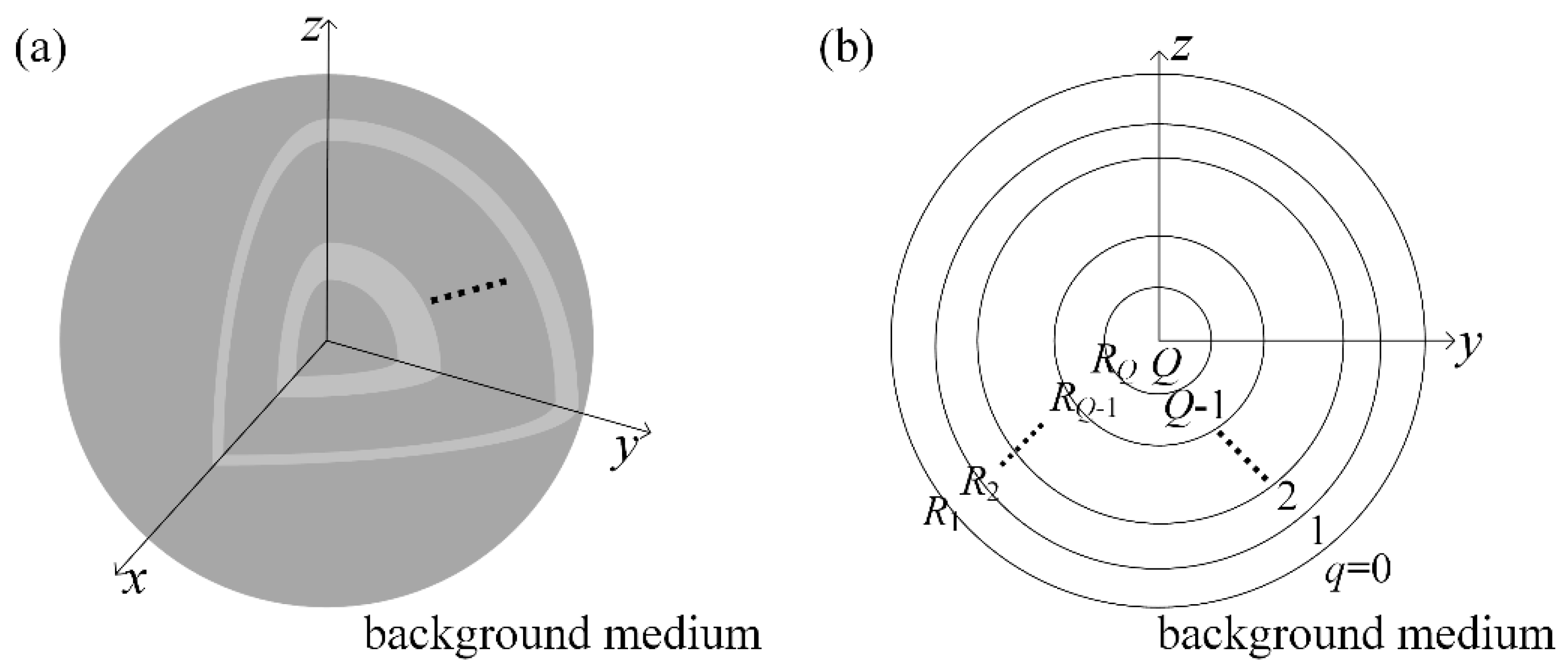
Figure 1a,b show the diagram of the proposed multilayered ACM sphere in a 3D view and a cross section in the
yz-plane, respectively. The multilayered ACM sphere is immersed in a conventional background medium (labeled as the zeroth region), whose mass density
ρ0 and bulk compressibility
β0 are both real and positive. The outer radius of the
q-th layer (
q = 1, 2, …,
Q) of the ACM sphere is
Rq, and each layer is characterized by the refractive index
nq and effective mass density
ρq. The effective mass density
ρq and bulk compressibility
βq for the
q-th ACM layer are expressed as
and
, respectively, whose phases are complex conjugates of each other. Here,
(
) denotes the amplitude of the effective mass density (bulk compressibility),
denotes a phase angle, and
is the refractive index of the
q-th ACM layer. For
and
, the sign “
” is taken, and the ACM features right-handedness (positive refractive index), while for
, the sign “
” is taken, and the ACM features left-handedness (negative refractive index). In particular, when
and
, the ACM is called a pure imaginary metamaterial, and the material exhibits ambiguous handedness. When
and
, the ACM degenerates into double-positive and double-negative materials, respectively.
Due to the spherical symmetry of the proposed ACM sphere, the channel modes used to describe the acoustic field distribution (see Equation (1)) are naturally spherical waves, which are a set of orthogonal separate variable solutions of the acoustic Helmholtz equation in spherical coordinates (
r,
θ,
φ). Here,
r,
θ and
φ denote the radius, angular and azimuthal angles in spherical coordinates, respectively. The case of axial symmetry is considered here, where the acoustic field is independent of coordinate
φ. Therefore, for
, the total acoustic pressure in the
q-th region can be expressed as
Here, and are the spherical Hankel functions of the first and second kinds with the order l, and is the Legendre polynomial of order l, respectively. The parameter kq = nqk0 denotes the wavenumber for the q-th region, in which is the wavenumber for the background medium and is the wavelength in the background medium. The expressions and represent the incoming and outgoing channel spherical waves of order l in the q-th region, with and being the corresponding complex amplitudes. Here, the time variant item is omitted for simplicity. The radial evolution of the spherical waves is given by the spherical Hankel functions, and the field evolution over θ is given by .
Because of the orthogonality of the spherical waves, the continuity of acoustic pressure at the interface
reads
while the continuity of radial acoustic velocity at
leads to
Here,
denotes the acoustic impedance of the
q-th region relative to the background medium, the scattering coefficient
is the ratio between the complex amplitudes of the outgoing and incoming spherical waves in the (
q-1)-th region,
and
are the first-order derivatives of the corresponding spherical functions,
, and
, respectively. According to Equations (4) and (5), the scattering coefficient for the (
q-1)-th region of order
l can be obtained as
Then, Equation (6) is a recursive formula that could apply to all .
Since the spherical Hankel functions diverge at the origin, the acoustic pressure field in the
Q-th region should be expressed as
where
is the complex amplitude of the penetrated channel spherical wave of order
l, and
is the spherical Bessel function of the first kind with order
l. By applying the continuous pressure and radial velocity boundary conditions at
, the scattering coefficient in the (
Q − 1)-th region, i.e.,
, can be expressed as
Here, is the first-order derivative of .
By iterating Equations (6) and (8), all scattering coefficients (q = 0, 1, …, Q − 1) can be obtained. Similar to the process for solving the scattering coefficients, the transmission coefficient in the q-th region, i.e., (q = 1, 2, …, Q), can be obtained accordingly by applying continuous boundary conditions. Then, the total acoustic field in the whole domain can be completely reconstructed from Equations (3) and (7) for a given incident pattern. Due to the orthogonality of the spherical channel waves, there is no interchannel scattering. According to Equation (2), therefore, the scattering matrix of the proposed ACM sphere system is diagonal with on-diagonal elements , and the scattering coefficient is also an eigenvalue of the scattering matrix for the proposed system. In the following, we focus on the extraordinary scattering properties of the ACM sphere by analyzing the scattering coefficient .
3. AEL Based on a Small Monolayer Sphere
Let us start with the simplest case of a small monolayer ACM sphere, i.e.,
Q = 1. Then, the scattering coefficient of the monolayer ACM sphere can be obtained by taking
Q = 1 into Equation (8), i.e.,
The AEL mode corresponds to a divergent eigenvalue of the scattering matrix, namely, a divergence scattering coefficient
for the proposed system. Therefore, the condition for the AEL mode, which could generate a strong spherical wave with the order
l, can be concluded from the zero of the denominator of Equation (9), namely
For simplicity, we define
and
, so Equation (10) can be simplified to
The function
is the ratio of the spherical Bessel function of the first kind to its derivative and therefore is real, while
is the ratio of the spherical Hankel function of the first kind to its derivative, which is complex. Thus, Equation (11) can be further expressed as
where
and
are the amplitude and phase of
, respectively. There are two kinds of solutions for Equation (12), denoted as:
If the amplitude of the mass density
is taken for the ACM sphere, the acoustic parameters of the ACM sphere are simply determined by the phase angle
and
, and Equations (13) and (14) can be rewritten as
Here, and satisfying Equations (15) and (16) represent the particular phase angle and refractive index of the monolayer ACM sphere, respectively, leading to the AEL mode, where the ACM sphere could generate a strong spherical wave with the order l at a given working frequency.
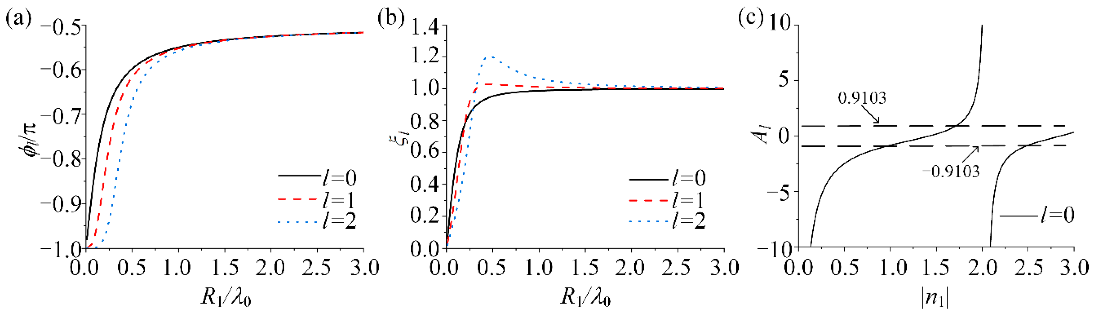
Figure 2a,b show the phase
and amplitude
of
(see Equation (12)) versus
, in which black solid, red dashed, and blue dotted curves correspond to
l = 0, 1, and 2, respectively. For
,
,
, and
(see
Figure 2a);
,
, and
(see
Figure 2b). Therefore, some values of
and
can be found to realize the AEL mode when
. Taking
l = 0 as an example,
Figure 2c shows the
for
l = 0 versus the refractive index
. The values of
that lead to the AEL mode for
l = 0 can be found to search the intersections of
(or
) (black dashed lines) and
(black solid curves). For example, for
l = 0,
and
satisfy Equation (15);
and
satisfy Equation (16). Similarly, when
l = 1,
and
for Equation (15);
and
for Equation (16). When
l = 2,
and
for Equation (15);
and
for Equation (16). It is worth noting that Equations (15) and (16) have more solutions with larger
due to oscillatory properties of the function
for a fixed order
l.
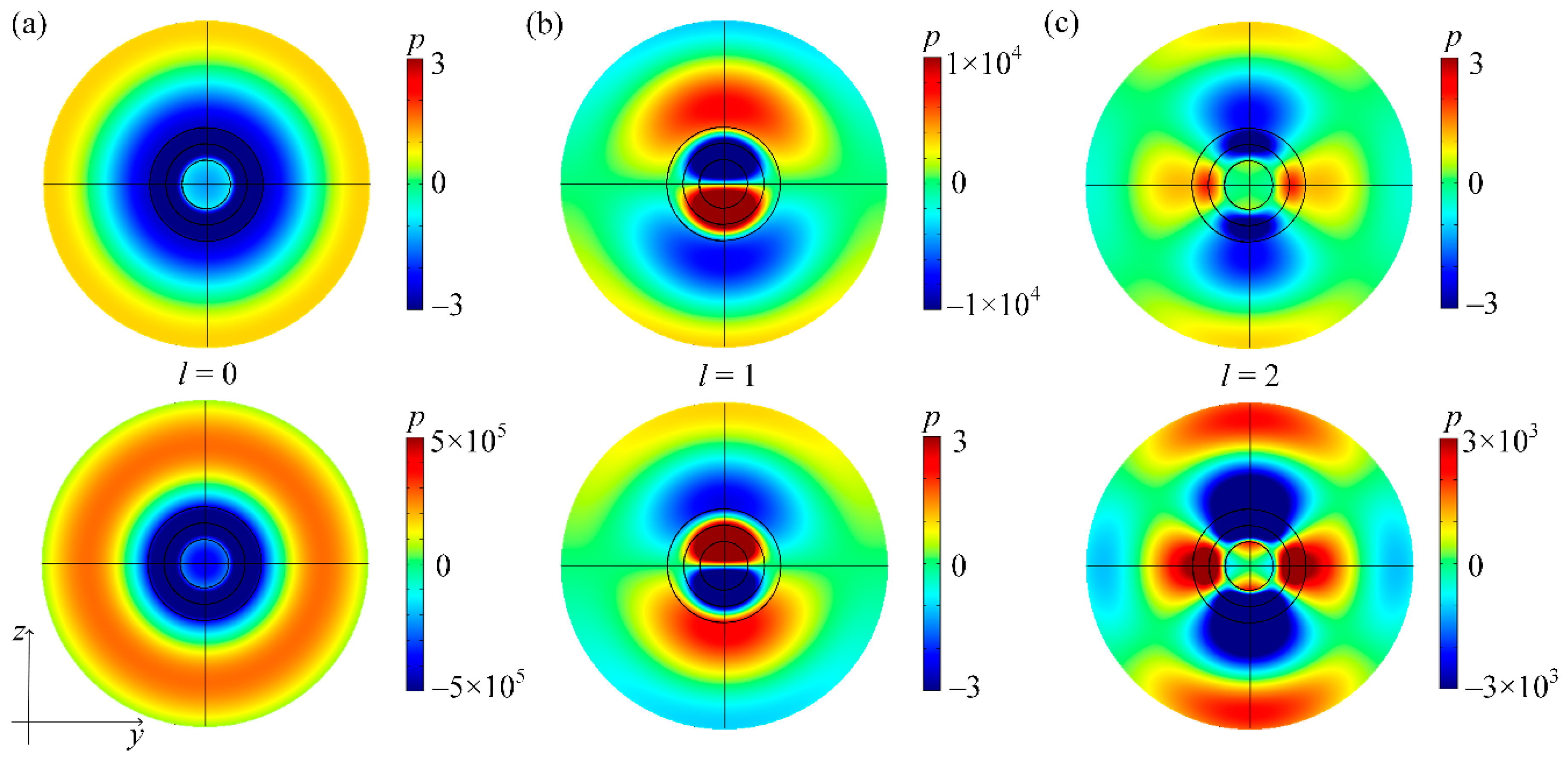
The AEL modes are further numerically simulated by using the finite element method based on the above analytical derivations.
Figure 3 shows the total acoustic pressure fields in the
yz-plane for spherical wave with an order
l impinging on an ACM sphere with particular acoustic parameters, in which
Figure 3a–c correspond to
l = 0, 1 and 2, respectively. Without loss of generality, the background medium is set as air with the mass density
ρ0 = 1.21 kg/m
3 and the bulk compressibility
in all simulations. Here, the sound speed of air
c0 = 343 m/s. The incidence wavelength is set as
, and the distribution of the incident pressure field at the outer simulation boundary (
r =
λ0) is set to
. The inner black circles in the figures denote the outer radius of the ACM sphere (
). For
l = 0 (
Figure 3a),
and
are taken to realize the AEL mode. Similarly, for
l = 1 (
Figure 3b),
and
are taken, while for
l = 2 (
Figure 3c),
and
are taken. For
l = 0, the acoustic field distribution shows the shape of concentric circles and is completely determined by the coordinate
r; when
l = 1, the acoustic intensity along the
z-axis is the strongest, and the field is symmetric about the
z-axis; when
l = 2, the maximum of the acoustic intensity is distributed along the
y-axis and
z-axis, and the acoustic field is symmetrical about the
y-axis and
z-axis. In all cases, the total acoustic pressure fields are very intense (see color bars) relative to the incidence. Therefore, the AEL mode is successfully realized based on an ACM sphere with appropriate parameters, where a strong spherical wave with the desired order
l is scattered.
4. CPA Based on a Small Monolayer Sphere
In contrast to the AEL mode, the CPA mode corresponds to a vanishing eigenvalue of the scattering matrix, namely, a vanishing scattering coefficient
for the proposed system. Then, the incident spherical wave with the order
l could be fully absorbed without any scattered waves. Therefore, the condition for the CPA mode can be concluded from the zero of the numerator of Equation (9), namely
By numerically solving Equation (17), based on a similar procedure for solving Equation (10), one can obtain a series phase angle (
) and refractive index (
) solutions for realizing the CPA mode with the desired order
l at a given working frequency. It is worth pointing out that Equations (10) and (17) have the same form but different kinds of spherical Hankel functions. Due to the complex conjugate nature between the first and second kinds of spherical Hankel functions, for the same radius
R1, the solutions (
,
) of Equation (17) have a special relationship with that (
,
) of Equation (10), namely
On the other hand, the CPA mode could be regarded as a time reversal counterpart of the lasing [
40,
41,
42,
43,
44,
45]. Therefore, an AEL mode always corresponds to a CPA mode where the acoustic constitutive parameters of the two modes are complex conjugates. For the proposed ACM sphere, the complex conjugate acoustic parameters directly lead to Equation (18). In the following, instead of directly solving Equation (17), we employ the particular parameters (
,
) for achieving the AEL (see previous section), together with Equation (18) to obtain the parameter solutions (
,
) for achieving the CPA.
Figure 4 shows the simulated total acoustic pressure fields in the
yz-plane where spherical waves with orders
l = 0, 1, and 2 are incident on ACM spheres with particular acoustic parameters, respectively. The radii (
R1) for all ACM spheres are
, with
as the incidence wavelength, and the distribution of the incident pressure field at the outer simulation boundary (
) is set as
. In the case of
l = 0 (
Figure 4a),
and
are taken to realize the CPA mode. Similarly, for
l = 1 (
Figure 4b),
and
; for
l = 2 (
Figure 4c),
and
. In other words, all the simulation parameters in
Figure 3 and
Figure 4 are the same, except that the acoustic parameters of the ACM spheres in
Figure 4 are complex conjugates with those in
Figure 3.
In contrast to the AEL modes (
Figure 3), the acoustic fields in
Figure 4 are weak (see color bars). Quantitatively, the values of the total fields at the outer simulation boundary are very close to
, respectively, which are equal to the incident pressure. Meanwhile, when
l = 0, the acoustic field presents the shape of concentric circles. When
l = 1 (2), the acoustic field is symmetric about the
z-axis (
y-axis and
z-axis). The field profiles outside the spheres maintain the shapes of 0th-order, 1st-order, and 2nd-order spherical waves, respectively, and no obvious interference pattern is observed. The incident spherical waves with desired order
l are thus totally absorbed without any scattering. Therefore, the CPA modes for spherical wave incidence with the order
l are realized based on the ACM sphere with appropriate parameters.
5. Simultaneous AEL and CPA Based on a Huge Monolayer Sphere
In the previous sections, it was demonstrated that by fine modulating the acoustic and geometric parameters of a small monolayer ACM sphere, an AEL or CPA mode with order
l could be realized at a working frequency. In this section, we will show that a huge monolayer ACM sphere can support the AEL and CPA modes simultaneously. When
is far beyond the incidence wavelength
, i.e.,
, the phases
of
for all orders
l approach
(see
Figure 2a), and the amplitudes
of
approach 1 (see
Figure 2b). Therefore, when
, together with
, the condition to realize the AEL mode (see Equations (15) and (16)) can be written as
Furthermore, when
, the function
will approach
Therefore, for even-order
l, the condition to realize the AEL mode can be expressed as
while that for odd order
l is
According to Equation (18), for even-order
l, the corresponding CPA mode condition can be expressed as
while that for odd order
l is
Comparing Equations (23)–(26) and (27)–(30), when () and [], the large ACM sphere will extremely amplify spherical waves with all even orders l and totally absorb spherical waves with all odd orders l simultaneously. In contrast, when () and [], the large ACM sphere will extremely amplify spherical waves with all odd orders l and perfectly absorb spherical waves with all even orders l.
Figure 5a,b show
with
l = even and
l = odd, respectively, in which
. Some values of
can be found to realize the coexistence of the AEL and CPA modes. For example, if
,
for even
l and
for odd
l. In this case, if the phase
of the ACM sphere is further set as
(
), the AEL (CPA) mode occurs for all even orders
l, and the CPA (AEL) mode occurs for all odd orders
l. Similarly, if
,
for even
l, and
for odd
l. In this case, by further setting the phase
of the ACM sphere as
(
), it could realize the CPA (AEL) mode for all even orders
l and the AEL (CPA) mode for all odd orders
l.
Figure 5c,d show the scattering coefficient
for orders from 0 to 5 when
and
, respectively, in which
and
.
Figure 5c,d show that
tends to zero for
l = 1, 3 and 5 (
l = 0, 2 and 4) and tends to large values for
l = 0, 2 and 4 (
l = 1, 3 and 5). These results demonstrate that the coexistence of the AEL and CPA modes could be realized with an ACM sphere of radius much larger than the incident wavelength. Here, the phase
of the ACM sphere must be
or
, which results in a special ACM called pure imaginary materials.
6. AEL and CPA for Multiple Orders Based on a Small Multilayered Sphere
Based on a small monolayer ACM sphere, the AEL or CPA modes are realized, but it can only amplify or absorb spherical wave with a single order
l. A monolayer ACM sphere with a radius much larger than the wavelength could simultaneously realize even (or odd) order AEL modes and odd (or even) order CPA modes, but the bulky geometry may limit its potential applications. In order to manipulate spherical waves with multiple channel orders simultaneously, a multilayered ACM sphere is considered because it contains material parameters with more degrees of freedom. Generally, a multilayered structure consisting of
Q layers could simultaneously manipulate spherical waves with total
Q orders [
46]. Here, a three-layered ACM sphere (
Q = 3) is proposed as an example, where the outer radius of each layer is
,
, and
, the incident wavelength is
, and the refractive indexes of three layers
are all set to 2 for simplicity, unless otherwise stated. Then, the scattering coefficient
can be obtained by iterating Equations (6) and (8).
We first aim to realize the AEL mode for order
l = 1 and the CPA modes for orders
l = 0 and 2, which requires
,
, and
, simultaneously. By numerically solving these three equations, one can finally find the required acoustic parameters of the three-layered ACM sphere as
,
, and
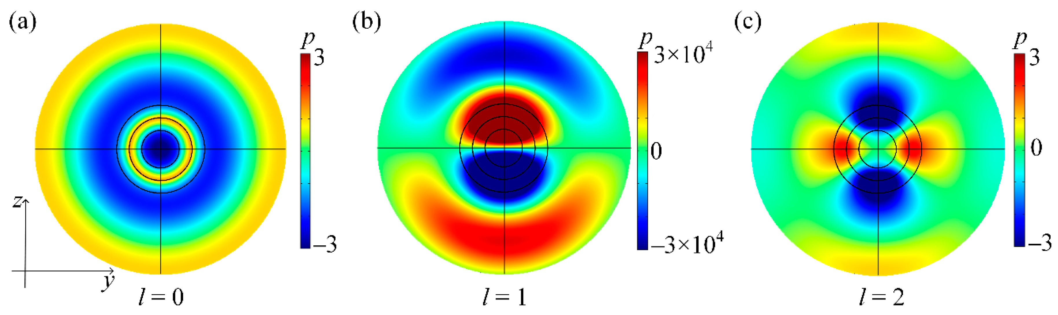
, respectively. For a three-layered ACM sphere with such acoustic parameters,
Figure 6a–c show the simulated total pressure fields in the
yz-plane where spherical waves with orders
l = 0, 1 and 2, respectively, are incident on the sphere. For
l = 0 (see
Figure 6a) and
l = 2 (see
Figure 6c), the values of the total fields at the outermost simulation boundary
are close to the corresponding incident pressure
, and no obvious interference pattern is observed in the background medium, indicating the realization of CPA modes for orders
l = 0 and 2. In contrast, for
l = 1 (see
Figure 6b), the total acoustic field in the air is far beyond the incidence field (see color bar), verifying the realization of the AEL mode for order
l = 1.
In addition, the multilayered structure could be designed to manipulate spherical waves with multiple orders at different frequencies
f. For the second example, a three-layered ACM sphere is designed to realize a CPA mode with order
l = 0 at 300 Hz, an AEL mode at 343 Hz for
l = 1, and a CPA mode at 400 Hz for
l = 2. By solving
at 300 Hz,
at 343 Hz, and
at 400 Hz simultaneously, it can be obtained that
,
, and
, respectively. The corresponding simulated results are shown in the upper panels of
Figure 7a–c. For
l = 0 (see
Figure 7a), the acoustic field is independent of
θ, while for
l = 2 (see
Figure 7c), the acoustic intensity is strong along the
y and
z-axes. In both cases, the values at the outermost simulation boundary
r = 1 m are very close to the corresponding setting incidence pressure
, and no obvious interference pattern is observed. Therefore, the CPA modes are realized for two orders at two frequencies. For
l = 1 (see
Figure 7b), the acoustic intensity is maximal along the
z-axis and minimal along the
y-axis. In addition, the total field far exceeds the incidence, i.e., the AEL mode occurs.
It is worth noting that since the AEL and CPA modes are each other’s time reversal counterparts, the time reversal results can be achieved by changing the sign of the imaginary acoustic parameters. For example, a three-layered ACM sphere with
,
, and
can realize an AEL mode at 300 Hz for
l = 0, a CPA mode at 343 Hz for
l = 1, and an AEL mode at 400 Hz for
l = 2. The corresponding simulations are shown in the lower panels of
Figure 7a–c, which are the time reversal patterns of those in the upper panels of
Figure 7a–c. That is, all simulation parameters are the same as those of the upper panels, except that the acoustic parameters for the lower panels are complex conjugates with those for the upper panels. As expected, the AEL mode at 300 Hz for
l = 0, the CPA mode at 343 Hz for
l = 1, and the AEL mode at 400 Hz for
l = 2 are all achieved.


