1. Introduction
Over the years, a certain amount of work has been devoted to the selected aspects of vehicle collision modelling, which can occur in real traffic situations. The problem undertaken in this paper has been partially mentioned in some previous works, e.g., in [
1,
2], which mostly relates the obtained collision simulation results to the analytical calculations enabling the comparison of them. Almost all of these problems have been related to the frontal impact of a vehicle, however, the mathematical models used there have not been fully developed in order to include some additional factors, such as the coefficient of restitution in the tangential direction.
The aim of this paper is to discuss the selected parameters related to road vehicle collision modeling, which can be useful especially for a forensic expert using crash mechanics in order to verify the correctness of his opinion on a specific case of a road accident that has previously been simulated. In addition, an identification of the crucial parameters in a frontal impact collision has been prepared using an example of a frontal and oblique crash. Such identifications have previously been conducted, e.g., in [
3], with the use of rigid barrier crash tests.
Of course, there is a class of specific software enabling both modeling and reconstruction of road accidents. For practitioners, however, the use of more complex software, e.g., based on the FEM numerical models of vehicles, is significantly limited. The most common applications are those having an extensive database of motor vehicle models, trucks, trailers, etc. Therefore, they can be used by forensic experts and appraisers for expertise in matters related to road accidents. This group includes the V-SIM software, which can also be used to verify the collision of vehicles and, for example, the typical maneuvers of vehicles.
One of the problems mostly paid attention to over the years has been the determination of the coefficient of restitution as an essential parameter when considering a vehicle crash. Several works have been devoted to, at least, specifying its magnitude, either for a frontal or a side impact collision (e.g., [
4,
5,
6,
7]). Some of them were based on tools, such as the spring–mass dampers, e.g., in [
8].
Various research have been conducted in order to understand the collision process via modeling, beginning with the planar motion of the colliding vehicles and ending with the more complicated models containing the analysis of three-dimensional motion during a crash, e.g., [
9]. Some specific problems related to collision modeling or reconstruction have also been the subject of multiple studies on high-speed collisions with small overlaps [
10] and kinetic energy loss during a collision [
11].
One of the major features of collision theory is the ability to perform computer simulations in order to verify, e.g., the correctness of either analytical calculations or forensic measurements. The use of some specific software has been presented in some work devoted to both providing the necessary information and the results related to some specific problems. For example, in [
12], a V-SIM software was presented with all the necessary features, while in [
13], a PC-Crash software was used to verify the real accident. In general, many works have been devoted to collision modelling in various aspects, such as low-speed collisions, impulse methods, reconstruction techniques, and more, e.g., [
14,
15,
16,
17]. Modeling the traffic of vehicles on different roads and load conditions as a separate issue has been discussed, e.g., in other papers [
18,
19,
20].
It is most important for a forensic expert to be able to easily use the most essential collision parameters to easily describe a collision and calculate the initial or final velocities, which can be sort of a proof of the correctness of a prepared expert.
V-SIM is a software designed to simulate vehicle collisions with two reference frames. The global reference frame is determined by the program user and describes a momentary location of a vehicle and other environmental elements. The origin of a local frame is located at the center of the mass of the vehicle. V-SIM uses the TM-Easy tire model and the kinematic model of the independent wheel suspension, and the vehicle model also includes a steering frame that complies with the Ackerman rule. The suspension’s rigidity and the weight of the vehicle can be adjusted by the user.
In V-SIM, a crash force model is used for the collision of motor vehicles, in which the forces during a collision develop continuously throughout the contact time of the simulation. The model proposes the development of the forces during the compression phase and then their change in the phase of restitution.
Users of the simulation software are often not aware of the simplifications and limits applied to collision models in this software and accept the simulation results as certain. However, accepting the wrong results can cause negative consequences during a court dispute, in which the presented simulation may often be confirmed.
The main question in this part was: is it possible to include a collision model and an additional impulse of a force resulting from the locked front wheels during the collision?
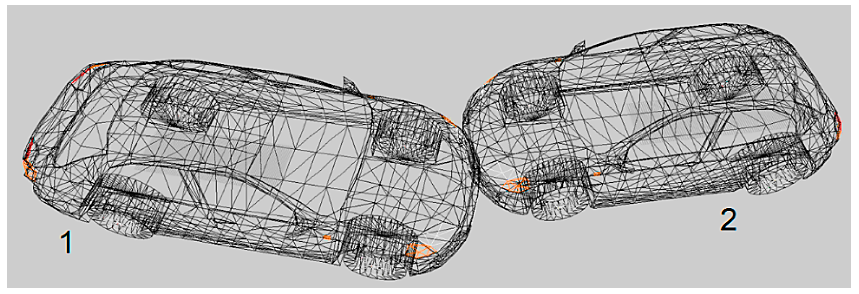
2. Simulation of a Collision between Two Passenger Vehicles
The simulation of a collision of two passenger vehicles (no. 1 and 2 in
Figure 1) has been prepared for the locked front wheels during the simulation.
While preparing the simulations, some general assumptions were made in accordance with, e.g., [
21]:
- -
Both vehicle models were considered linear and their mass-inertia parameters were adopted according to the V-SIM’s database.
- -
The vehicles performed a planar motion during the impact, which took place on a dry road surface with a coefficient of adhesion μ = 0.8.
- -
Before the impact, the vehicles were moving at 70 km/h (19.44 m/s, vehicle no. 1) and 90 km/h (25 m/s, vehicle no. 2).
- -
The total mass of vehicle no. 1 was set at 1410 kg, while the total mass of vehicle no. 2 was at 1125 kg.
- -
The coefficient of restitution was assumed by the program at R = 0.04.
- -
The simulated collisions of the vehicles were frontal and oblique, so the occurrence of the impulses of the colliding forces in a tangential direction could not be omitted.
The impact plane is understood to be perpendicular to the road surface and, at the same time, tangential to both the surfaces of the colliding vehicles [
21]. The simulation of a collision between two passenger vehicles was prepared as a case of a collision with the front wheels locked during the crash.
In
Table 1, the selected results of the locked simulation are presented. This set contains both the translational and the angular velocities before and after the collision. Additionally, the masses and the moments of inertia of both vehicles are presented as the parameters necessary in the analysis in a mathematical sense. On this basis, the authors attempted to show that parameters from a mathematical point of view could be useful for a forensic expert to validate accident reconstructions.
Based on the obtained results (
Table 1), it is necessary to mention that the post-collision velocities can be decomposed into two components in the case of a planar motion performed by the vehicles (along the normal and the tangential axes of the
Ont local coordinate frame), where
O is the geometric center of the collision.
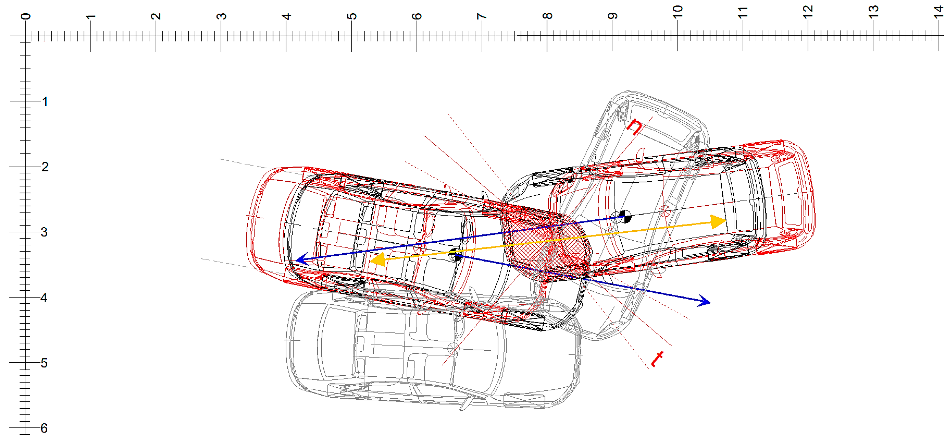
Initially, the velocities obtained as a result of the simulation were presented along the axes of the global and inertial
O’xy frame (
Figure 2). The first and foremost step in switching to the analytical approach is to transfer them to the assumed natural coordinate frame
Ont, which is attached to the geometric center of collision at the moment of initial contact. In order to do so, some geometric dependencies will be necessary, which will be presented in
Section 3.
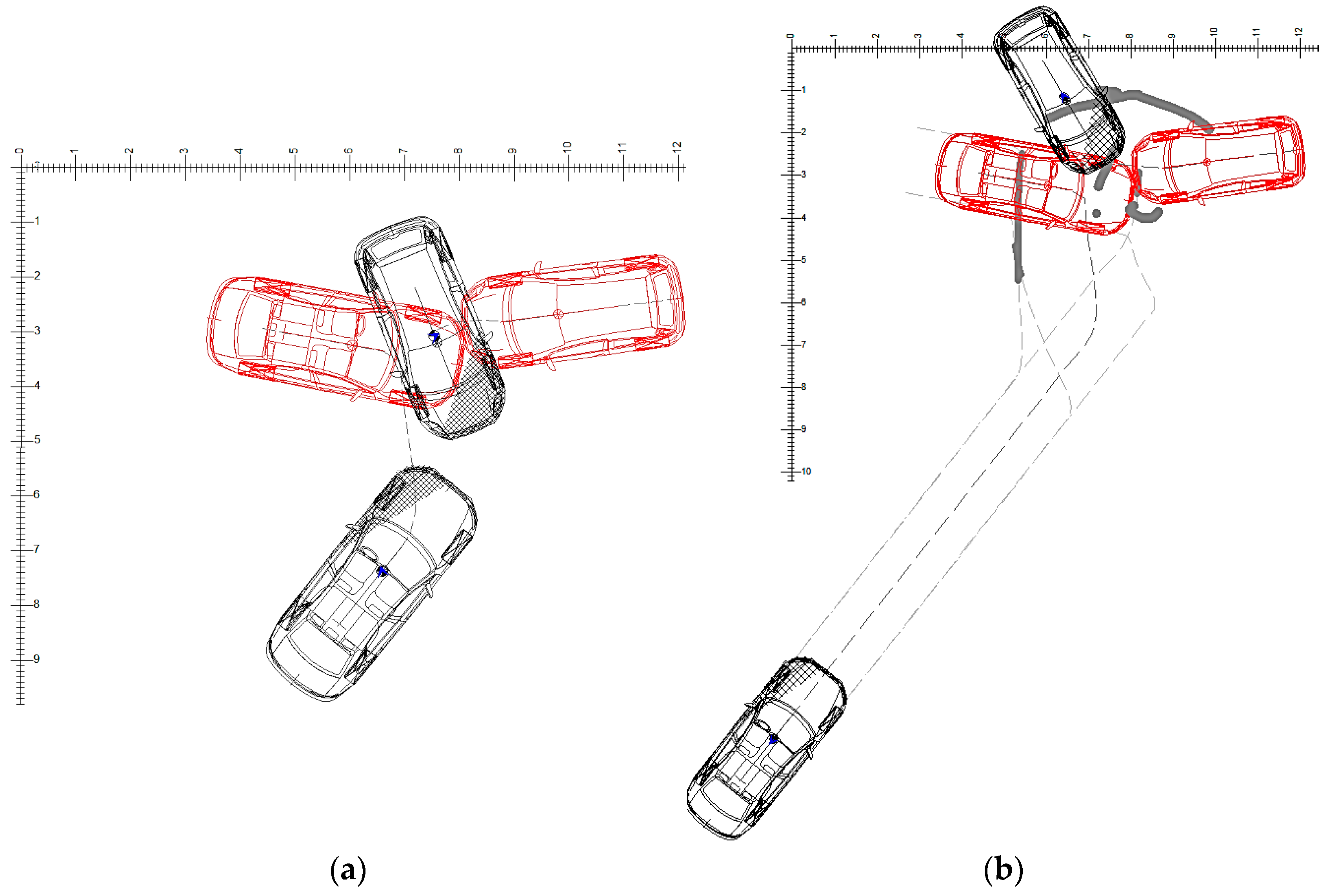
One more aspect of a computer simulation can be observed here. The visible effects of running the simulation of locked front wheels are presented in
Figure 3a and are compared to unlocked wheels in
Figure 3b.
Interestingly, though, the front wheels locking during the crash seemed to provide more realism to the discussed case (
Figure 3a), as both vehicles seemed to rotate rather than to move forward. The discussed collision was frontal and oblique, so the occurrence of the impulses in a tangential direction had to be taken into account. The mutual plane of impact of the vehicles is perpendicular to the road surface and at the same time tangential to both of them. A mathematical model of such a collision will be adopted based on [
21].
3. Identification of the Parameters Crucial for the Analytical Calculations
In order to properly proceed with the analytical calculations of the discussed collision, it seems appropriate to transform the global
O’xy frame in which the velocities were determined by V-SIM to a local
Ont frame, which seems more useful in mathematical modeling due to the fact that its origin
O is at the point of an initial contact between the colliding vehicles. However, this may not be so obvious because of a variety of possibilities in which the axes of the
Ont frame may be located, as the contact area between the vehicles is usually not a single point. Therefore, in the presented example, point
O was adopted in the middle of the section to determine the initial contact between the vehicles (
Figure 4). The axes
Ot and
On could also be located differently versus both of the colliding vehicles. Usually, the software used in simulations adopts the point of initial contact between the vehicles, and so it was in this case. Then, it was adopted such that the
Ot axis is located as easily as possible, i.e., along the plane of one of the vehicles. Hence, the axis
On must be perpendicular to
Ot and the proposed configuration of the adopted
Ont frame is shown in
Figure 4. Although the adoption of both axes relates only to the considered example, the method for evaluating the results obtained in the simulation can be valid for other cases.
To properly describe the collision in the aspect of mathematical modeling is also necessary for making certain assumptions regarding the simplifications of the collision modeling which will not affect the considered phenomena. The quasi-stiff models of the vehicles have been assumed with the specified mass and stiffness, which did not change during the collision. The motion of the vehicles was considered on a flat road surface. However, in further research, the possibility of both uneven and sloping roads can be taken into account, which could lead to a resultant motion. In more complicated cases, a non-linear suspension may be included, but it seems that during the collision it does not have a significant influence on the analyzed phenomena. Additionally, the additional impulses due to the locked wheel have been omitted and will be included in further studies.
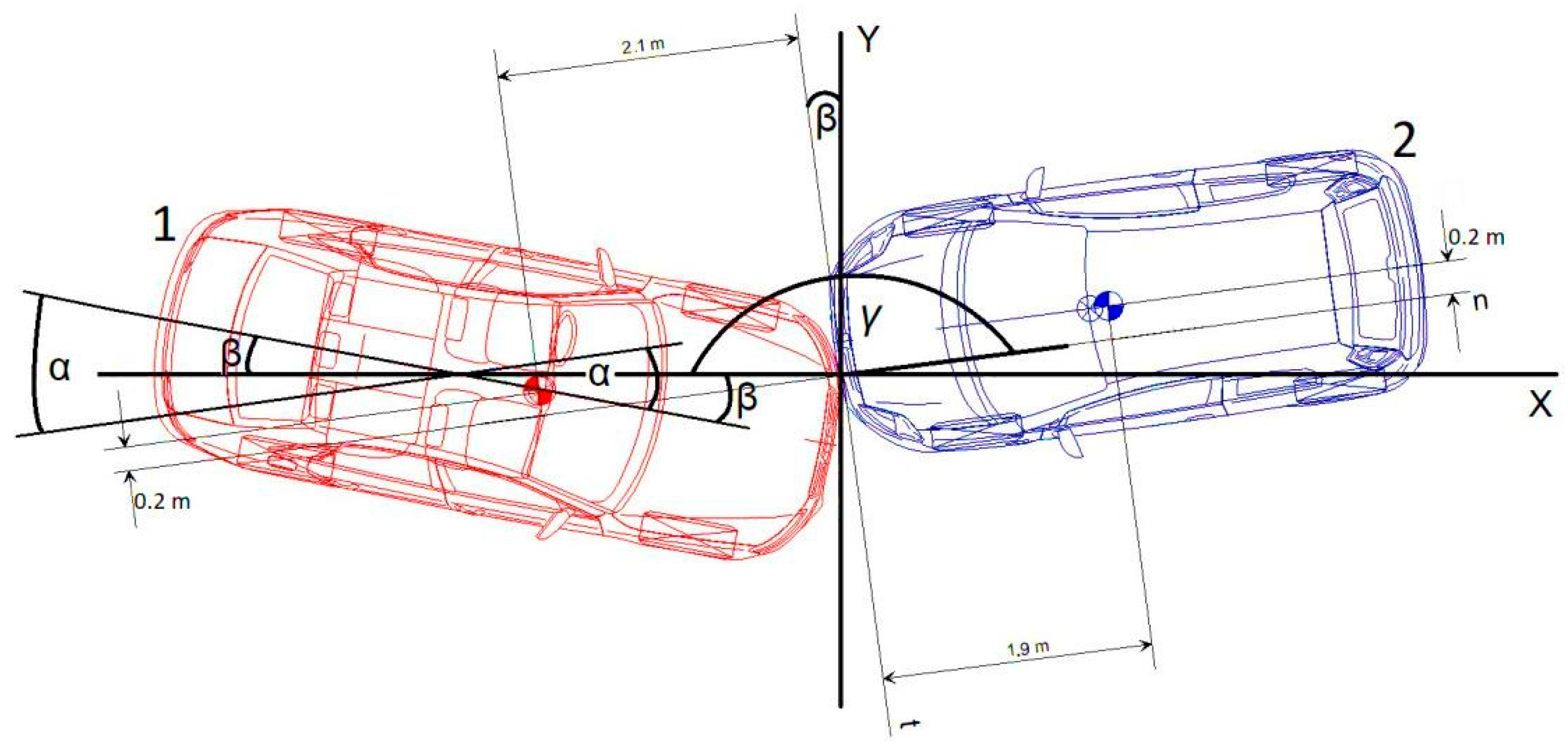
It seems convenient to present the adopted method graphically so that all the necessary trigonometric transformations can be easily applied. Therefore, in
Figure 4, the mutual location of both vehicles is presented at the moment of initial contact, along with the necessary dimensions and the adopted
Ont coordinate frame. At first, only the planar view is necessary, as the planar motion will be considered.
To determine the velocity components along the normal and the tangential directions versus the plane of collision, an angle between the speed vector and the longitudinal axis of each vehicle was selected from the collision protocol provided by V-SIM. This angle was then used to distribute the speed into a normal and a tangential velocity. Therefore, it seems necessary to relate the applied local
Ont frame to the global
O’xy with the specific angles which are marked in
Figure 4 and are as follows:
- -
α1—the angle between the speed of vehicle no. 1 and the normal axis (n) of the adopted Ont frame, which determines a division of the speed into two components (normal and tangential).
- -
β—the angle between the speed of vehicle no. 1 and the x axis of the global O’xy frame, which determines its initial position versus the O’xy frame.
- -
γ—the angle between the speed of vehicle no. 2 and the x axis of the global O’xy frame, which determines its initial position versus the O’xy frame.
Taking into consideration the given angles a simple formula to determine the
α can be used:
Both
β and
γ are known as they are the angles of the initial positions of vehicles no. 1 and 2 determined by V-SIM. Therefore, for the discussed example, assuming that the positive angles of the vehicles are measured clockwise, they are:
and the
α will then be:
This angle will be very important in further considerations.
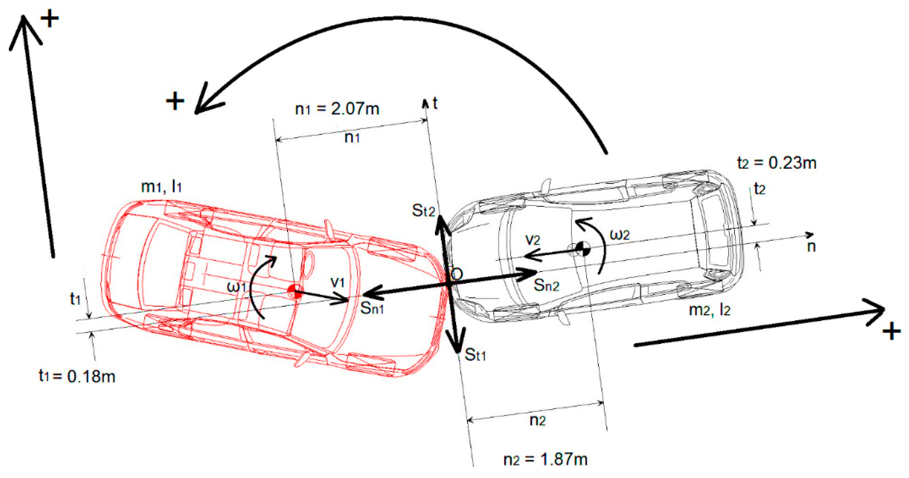
Next, the necessary parameters have been attached to the initial locations of the vehicles. Taking into account the collision with the tangential impulses of the impact force in
Figure 5, the physical model of the crash is presented for the case of the locked front wheels during the collision with the positive directions marked. The impulses of the collision forces for each vehicle (
Sn1,
St1,
Sn2, and
St2, respectively) are presented and are marked as scalars because they are the components of the resultant impulses acting on each vehicle.
Additionally, the necessary dimensions, the masses, and the moments of inertia of both vehicles are marked in
Figure 5.
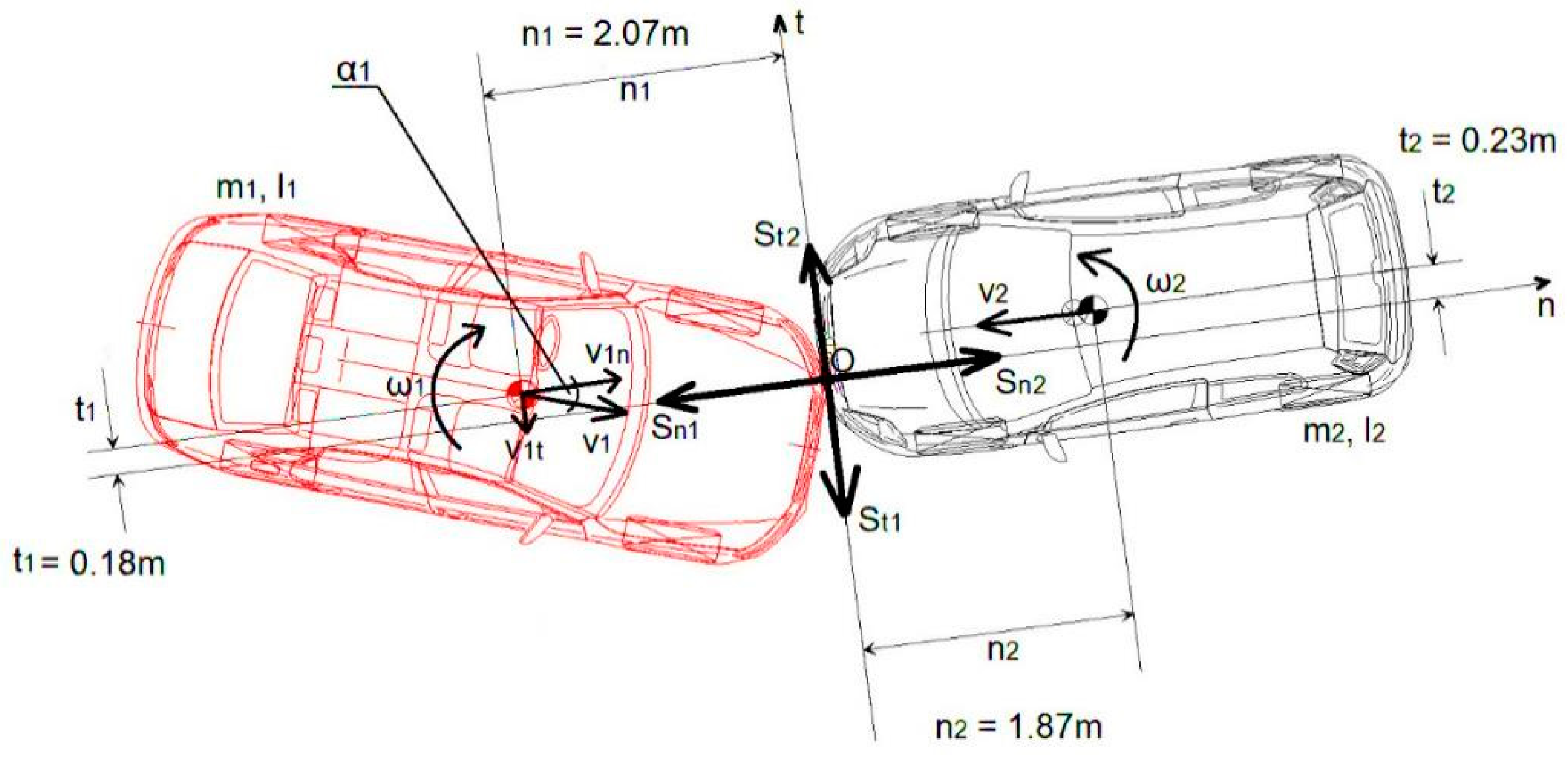
In
Figure 6, the angle
α1 used in the distribution of the speed into the tangential and the normal velocity is presented as well as the angular velocities, respectively, for vehicles no. 1 and 2. These components have been used to determine the kinematic state of both vehicles after the collision.
If a forensic expert was to verify the simulation results, a general model of collision could be used to conduct some simple analytical calculations, with the use of the following formulas:
- -
in the direction normal to the impact plane (along the
On line):
- -
in the direction tangential to the impact plane (along the
Ot line):
- -
in the direction of rotation on a plane of the road, in accordance with the selected angular velocities:
As a result, the kinematic state of motion at the end of the collision is determined:
where:
- -
Sn1, St1, Sn2, and St2—components of the force impulses of vehicles no. 1 and 2, respectively.
- -
v1n and v2n—the normal velocity of vehicles no. 1 and 2, respectively, before the collision.
- -
v1t and v2t—the tangential velocity of vehicles no. 1 and 2, respectively, before the collision.
- -
ω1 and ω2—the angular velocity of vehicles no. 1 and 2, respectively, before the collision.
- -
n1, t1, n2, and t2—coordinates of the center of mass of each vehicle in relation to the geometric center of the collision (point O).
α1 is the angle between the speed of vehicle no. 1 and the
On axis (
Figure 6). The markings adopted in this chapter refer to the symbols used in the equations of the analyzed collision. The index ‘1’ refers to the parameters of vehicle no. 1 (
Figure 5 and
Figure 6) and ‘2’ specifies the parameters of vehicle no. 2 (
Figure 5 and
Figure 6 as well). The indexes ‘
n’ and ‘
t’ denote the normal and the tangential directions, respectively.
Distances
between the centers of mass of the vehicles and the geometric center of the collision (O) were measured in V-SIM for the initial positions of both vehicles at the beginning of the mutual contact, i.e., the initial moment of collision (
Figure 6).
The determination of the velocity components along the normal and the tangential directions versus the plane of collision (a vertical plane of mutual contact between the vehicles) required the α1 angle. Although these components are marked with an arrow not matching the scale of the vectors, the main aim of presenting them was to highlight their importance as the parameters used in the mathematical model of the analyzed collision.
If the measured
α angle is taken into account, then the components of the velocity of vehicle no. 1 (
Figure 6) will be:
v1n =
v1cos
α,
v1t =
v1sin
α.
There is a simplification in the given case as the velocity of vehicle no. 2 will contain only the normal component, so v2t is zero and the longitudinal component v2n = v2.
The obtained set of six Equations (5)–(7) contains six unknowns, i.e., the post-collision velocities (
and four components of the impulse of a collision force (
as shown in
Figure 6. However, the velocities and the angular velocities require knowing the impulses of the collision force for each vehicle.
In a simplified way, we can assume that the impulses
S1 and
S2 are equal because the colliding vehicles are regarded as one body during the collision. Of course, in a more complex analysis, both impulses could be determined as integrals of the colliding forces of both vehicles, primarily depending on their masses and velocities. However, for a practical analysis, a simplification regarding the equality of these impulses is as follows:
can be a hypothesis resulting from the crash mechanics theory (e.g., [
21]).
The main problem is dividing these impulses into the normal and the tangential components. Of course, a formula can be used:
thanks to which, two additional equations can be obtained for the components of the impulses.
A hypothesis related to the friction can also be used. Let us assume that the collision between the vehicles causes friction between their surfaces. Hence, adopting a vicarial coefficient of adhesion between the colliding vehicles (
µ), one could apply such equations:
could supply Equation (9). In that way, a simplified collision model is correct enough to be used by a forensic without any complicated mechanics being used as a tool for verification of the obtained simulation results.
4. Conclusions
From the calculations, it can be observed that after the adoption of the collision model for vehicles regarded as bodies with rough surfaces, the coefficients of restitution do not have to be used in a simplified mathematical analysis of a collision. In practice, such a collision model could be considered as a tool for the preliminary impact assessment and testimony, as a verification of the pre-collision speed in the process of accident reconstruction. This is obviously a very simplified, yet non-troublesome, model.
Some general remarks can be made here. Firstly, the impact force impulse is known and presented in the collision protocol. Secondly, given that certain assumptions are made, this impulse can be divided into two components in planar motion and be used by a forensic expert for a simple verification of the results obtained in simulations of a collision in a designated software.
In the presented case, the collision angles seem to play the most important role as well as in the generalized coefficient of adhesion between the surfaces of the colliding vehicles (µ), which can be adopted as a mix of steel, plastic, and glass, considering the materials used in the production of the front parts of the vehicles in general. Therefore, within the main parameters necessary to properly handle the frontal oblique, collision through analytical calculations can be included in the masses, the velocities, the general impulses of the impact forces, as well as the angles discussed above and the vicarial coefficient of adhesion between the colliding vehicles (µ).


