1. Introduction
At present, the operating mileage and the number of Electric Multiple Units (EMUs) of high-speed railways in China account for around 2/3 of the world’s total [
1], ranking first in the world. However, power quality issues of negative sequence and voltage fluctuation are becoming more serious caused by the increase in traffic volume, single-phase connected traction transformers, mixed operation of locomotives and so on [
2]. In addition, the access of a large number of locomotive power electronic converter devices has caused new problems. Due to converters lacking inertia and damping compared to traditional generators and motors, it is easy to cause low-frequency oscillation phenomena; converters are also high-frequency harmonic sources, causing high-frequency resonance problems. These problems have brought challenges to the safe and stable operation of the high-speed railway, and it is necessary to continue the research on the power quality management of the traction power supply system [
3,
4,
5].
At present, traditional power quality management devices are divided into two categories: the upgrading and optimization of the traction power supply system itself and the supplementation of power quality management devices. The former is expensive and difficult to solve the power quality problems of existing lines, while the latter is difficult to take into account comprehensively all functions of suppressing harmonics, improving power factor and inertia, and eliminating negative sequence components [
2]. In the 1980s, Japanese scholars proposed Railway Power Conditioner (RPC), which could solve power quality problems comprehensively [
6]. However, the traditional RPC devices were connected back-to-back by two-level voltage source converters, which would generate a large number of harmonics. In addition, the voltage withstands capacity of switching devices is limited [
7,
8]; it needs to introduce step-down transformers [
9] and filter device, which is too expensive, bulky and inefficient [
2]. Therefore, this paper adopts MMC type RPC (modular multilevel converter, MMC-RPC). While solving the harmonic, negative sequence and reactive power problems, it has better quality, efficiency and reliability by increasing the number of voltage levels of each module and the number of modules in series to improve the total voltage level. For such a reason, MMC-RPC can be directly connected to the traction network without using the step-down transformers. Compared with traditional RPC, MMC-RPC has smaller harmonic components due to Carrier Phase Shift (CPS) modulation. And the switching frequency of each sub-module is low, which reduces the switching loss [
10]. Furthermore, the modular structure of the MMC-RPC not only expands the capacity of the converter, but also reduces the difficulty of maintenance.
To improve the control effect of the RPC, scholars have carried out much research on the topology and control strategy of the RPC. One study [
11] presented a current compensation (CP) method to balance the active power, compensate the reactive power and suppress harmonics by calculating the active current, reactive current, and harmonic current references. However, it is only applicable to the traditional RPC and traction power supply systems using
V/
v transformers. The authors of [
12] proposed a closed-loop voltage equalization control strategy based on CPS modulation for three-leg MMC-RPC, which uses the capacitor voltage balance control between sub-modules and the interphase capacitor voltage average control to obtain the average correction of capacitor voltage. However, it is still affected by the sudden change of power to lose control and stability. The authors of [
13,
14] adopted CP and energy balance control for the MMC-RPC system. However, it is difficult to maintain the stability of the system frequency when the traction load changes dynamically due to the lack of inertia support. The authors of [
15,
16] adopted a direct power control without a phase-locked loop, which improves the dynamic performance of the system. However, it still cannot provide inertial support for the traction power supply system, and due to the heavy load and dynamics of the traction load, its anti-disturbance performance is also limited due to the lack of damping support.
In recent years, the research on Energy Storage (ES) based on MMC topology is becoming mature. However, most ES units are combined with three-phase MMC. ES units are distributed connection schemes; that is, they are connected parallel to the DC link of the MMC submodule directly or through DC/DC converters [
17,
18]. DC/DC converters are either isolated or non-isolated. In this paper, a distributed ES scheme is adopted, in which super-capacitors (SCs) are used as ES units, and they are connected in parallel to the DC side of the sub-module in one bridge-leg of the MMC through the non-isolated DC/DC converter [
19]. Since the SC charges and discharges rapidly, it is more suitable to be used as an intermittent power buffer rather than a continuous power supply [
20]. Therefore, it is necessary to use DC/DC converter to improve the voltage level of the ES unit. At the same time, the DC/DC converter can decouple the SC from the DC link support capacitor of the submodule and reduce the DC filtering demand.
The research focus of this paper is to achieve the comprehensive management of power quality, realize the energy conservation of traction power supply systems through multi-functional power electronic equipment, and improve the stability and anti-interference ability of the system through new controls. Therefore, this paper applies an ES-type MMC-RPC system to realize the management of power quality and energy utilization, and proposes new controls for the MMC-RPC system to improve the system stability. Firstly, this paper established the mathematical model of the MMC-RPC and analyzed its dynamic characteristics. A two-stage circulation suppression is adopted to suppress the double frequency circulating current component of the MMC-RPC, ensuring the stability of the MMC-RPC. A VSG control is adopted to provide the support of inertia and damping, and a small signal model is established to verify the stability of the system. Furthermore, for the SC-type ES system, a virtual DC motor (VDCM) control for the bidirectional DC/DC converter is adopted to enhance the stability of the system [
21,
22]. The joint VSG-VDCM control can provide better steady-state and dynamic performance compared to other controls [
23]. Finally, the effectiveness of the controls of the MMC-RPC is verified by the simulation on the Matlab/Simulink platform.
2. Principle of MMC-RPC
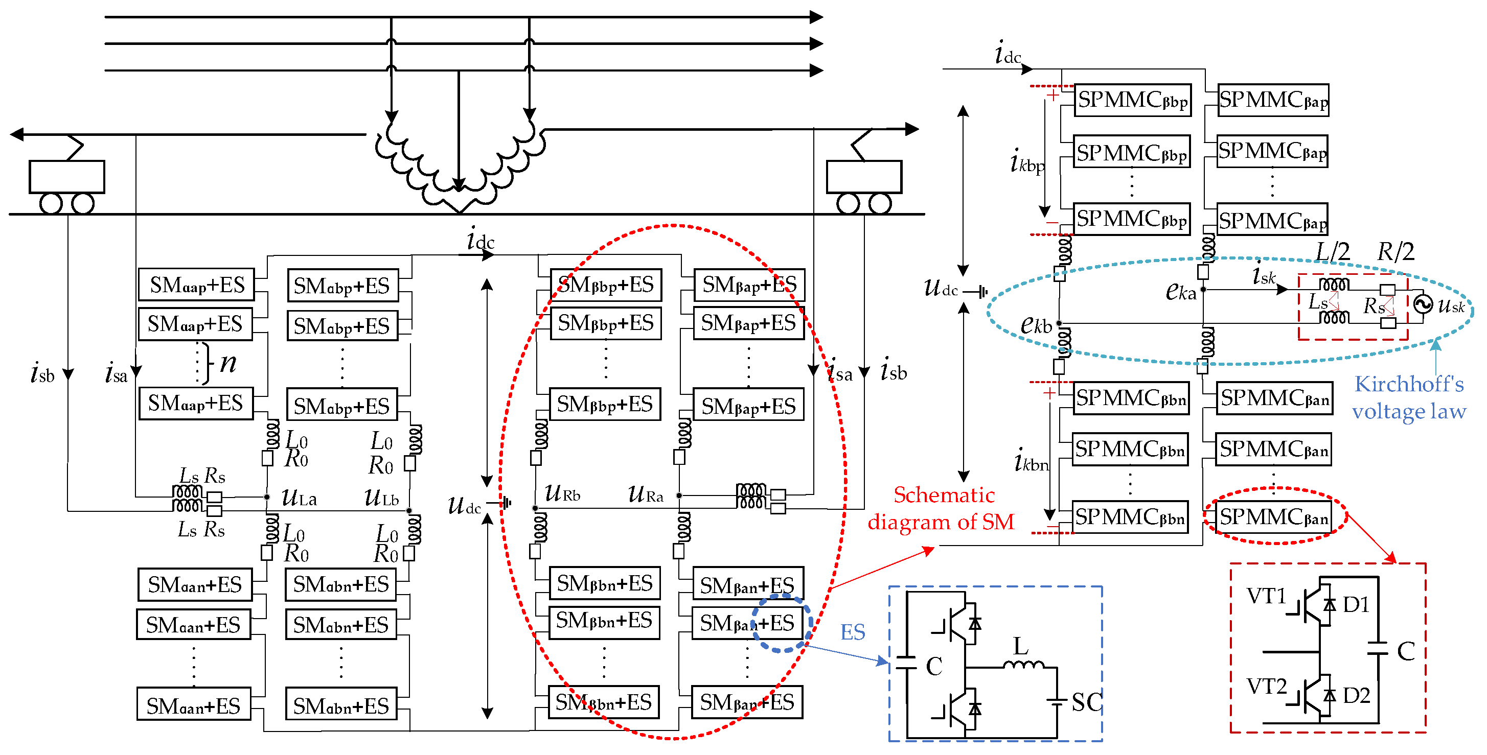
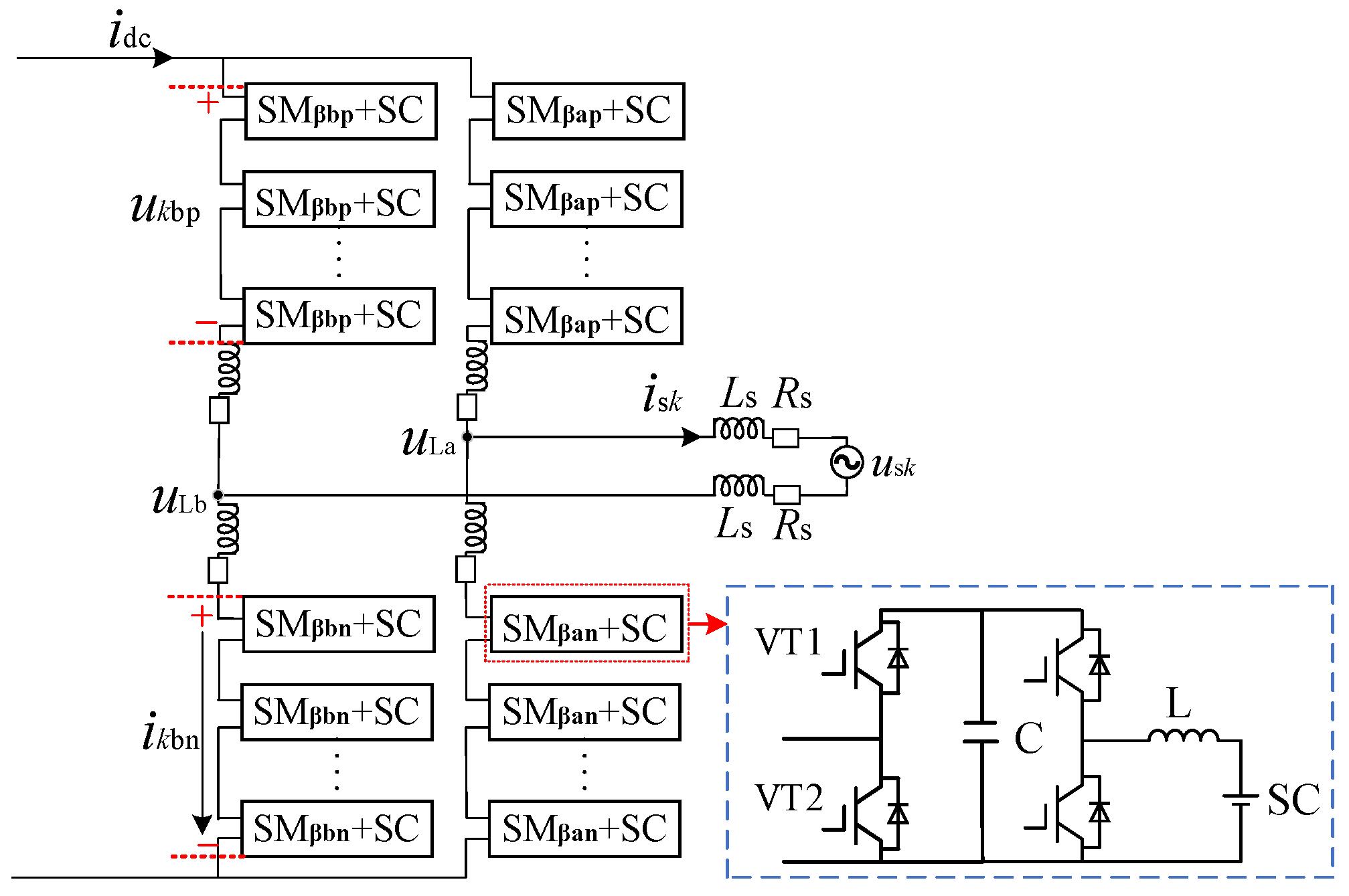
The ES type MMC-RPC and its application in the traction power supply system are shown in
Figure 1. The topology is mainly composed of back-to-back modular multilevel converters (MMCs) and SC-type ES units. In the traction power supply system, the 220 kV three-phase voltage is transformed to the value of 2 × 27.5 kV through the traction transformer. And the MMC-RPC system is directly connected to the traction power supply arm. Through the MMC-RPC system, energy integration and power quality management of two arms are realized. Finally, SCs are connected in parallel with the DC link support capacitor of the submodule to utilize regenerative braking energy through the DC/DC converter.
Figure 1 also shows the single-phase MMC (SM) topology structure on the inverter side of the MMC-RPC system, and the MMC submodule structure is shown in the lower right corner. The SM structure is composed of left and right bridge legs, and each bridge leg is composed of submodules, bridge-leg inductance and resistance. The bridge-leg inductance has three functions: (1) Suppress the charging current on the bridge leg when the converter is started. (2) During the normal operation of the converter, the circulating current in the bridge leg is suppressed. (3) When the DC-link short-circuit fault occurs in the converter, the short-circuit current is suppressed.
The topological structure of MMC-RPC can be obtained from
Figure 1; it is defined that the left and right power supply arms are α and β phases, respectively. Since the structure of each phase and each bridge leg of MMC-RPC are the same, a and b are defined as the left and right bridge legs in one phase, and
p and n represent the upper and lower parts of one bridge leg, respectively, where:
usk (k = α, β) is the AC voltage of each phase;
isk is the AC current of two power supply arms;
ukjp and ukjn (j = a or b) are the voltages of the upper and lower bridge legs of each phase;
ikjp and ikjn are the currents of the upper and lower bridge legs of each phase;
ukj (j = a or b) is the ground reference voltage of the AC port of the bridge leg;
R0 and
L0 are the equivalent resistance and inductance of the bridge leg in
Figure 1, respectively;
RS and LS are the equivalent resistance and inductance at the AC side;
idc and udc are the DC-link current and voltage, respectively.
According to
Figure 1, Kirchhoff’s voltage law is used to analyze the AC side and DC side circuits of the MMC-RPC, and the port equations on the AC side and DC side of the MMC-RPC are [
15]:
By solving Equation (2), the voltage on the AC side and DC side of the MMC-RPC can be obtained [
15]:
According to Kirchhoff’s theorem, we have:
According to Equations (2)–(4), the relationship between bridge leg current and voltage can be obtained: iap = ibn, ian = ibp, uap = ubn, and uan = ubp.
Since the output of the MMC-RPC is a single intersection flow and has only a single degree of freedom, it cannot separate the instantaneous active power and reactive power through Park transformation such as the three-phase MMC. Therefore, with the help of SOGI, this study constructs a virtual component orthogonal to the actual quantity, to delay the phase of the single-phase component by 90 degrees. The transfer function of SOGI is [
10]:
After constructing the orthogonal virtual component, equations of AC quantities in dq coordinate system can be obtained in (6), and the active and reactive power of single phase system can be extracted in (7) [
10]:
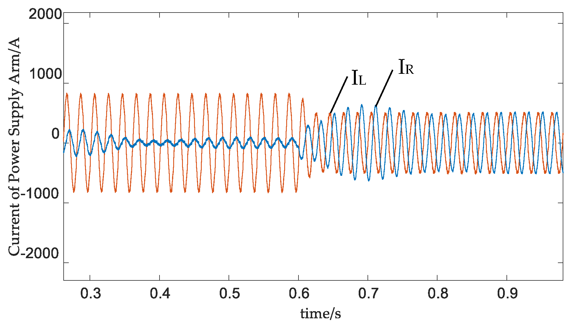
Through the above single-phase instantaneous power calculation method, the active power PL, PR, reactive power QL, QR of the load fundamental wave on the left and right power supply arms can be obtained, realizing active power balance, reactive power compensation and harmonic power suppression.
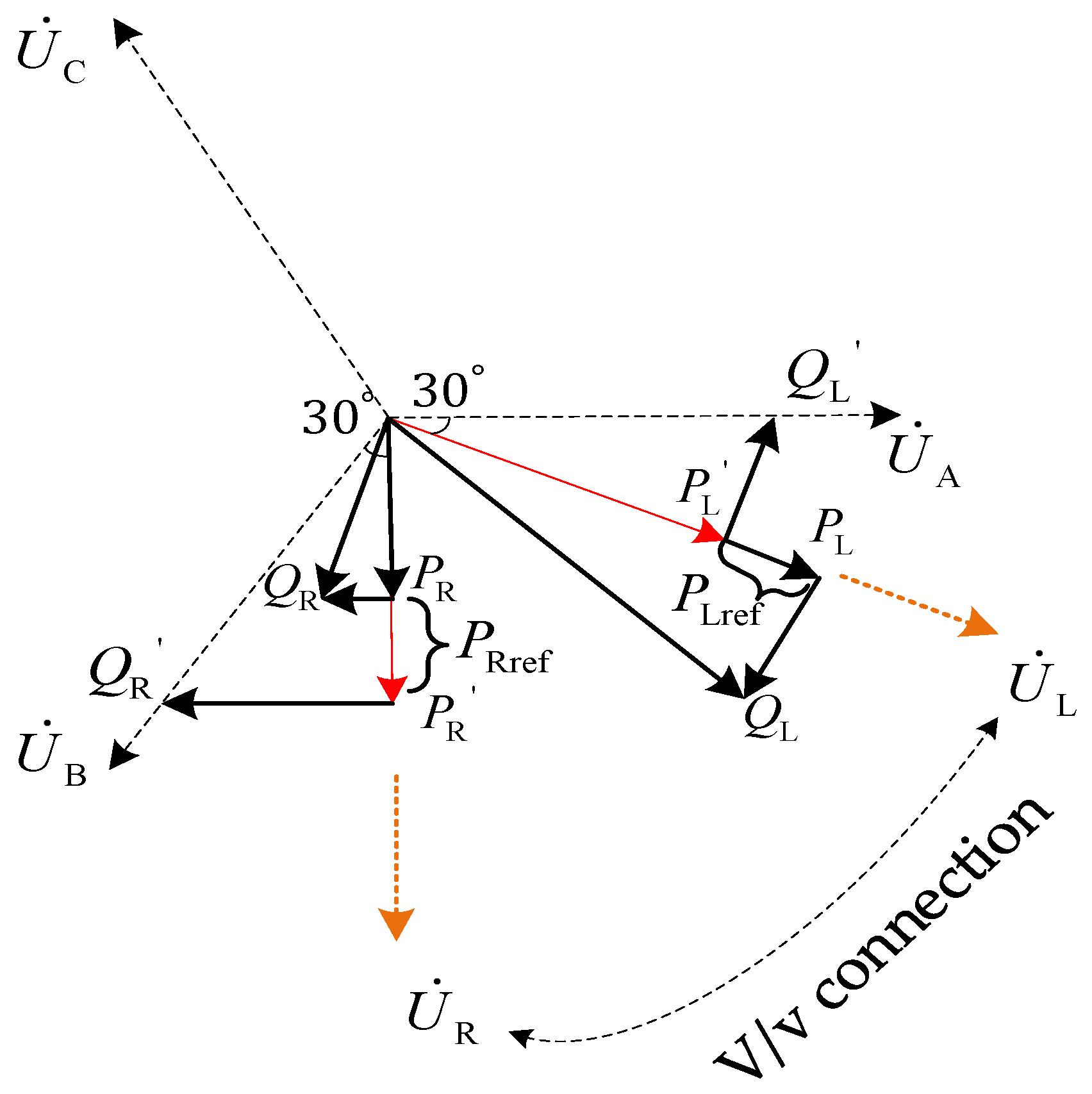
Figure 2 shows the power compensation diagram under heavy load on the left arm and light load on the right arm of the traction network.
UA,
UB and
UC are the three-phase voltages of the power grid.
PLref,
PRref,
QLref and
QRref are the active power and reactive power compensation reference quantities of the traction power supply arms. In order to achieve active power balance, MMC-RPC needs to transfer 0.5|
PL −
PR| power from the right power supply arm to the left arm with the heavy load, to obtain the expected power
PL′ =
PR′ for two power supply arms. Secondly, considering the relationship between the primary and secondary sides of the traction transformer in
Figure 2, the left and right power supply arms compensate
PL′tan30° +
QL and
PR′tan30° −
QR reactive power, respectively, to realize the three-phase current balance on the primary side of the
V/
v traction transformer, and eliminate the negative sequence current. Finally, according to the distorted current existing in the system in the actual simulation, the power reference components
PLH,
PRH,
QLH and
QRH of harmonic suppression are superimposed to obtain the references:
3. VSG Control
3.1. VSG Model
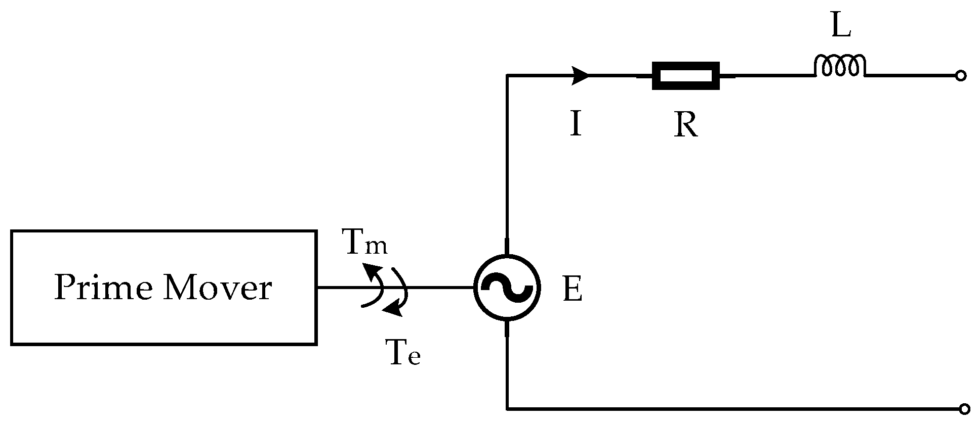
In order to realize the VSG control of MMC-RPC on the inverter side, it is necessary to simulate the output power characteristics, inertia and damping characteristics of the synchronous generator. The second-order mathematical model of synchronous generator includes both rotor mechanical equation and stator electrical equation, covering the basic characteristics of synchronous generator. The simplified model of the synchronous generator is shown in
Figure 3. By taking the rotor motion equation of the synchronous generator as the mechanical model of the VSG and the stator electrical equation as the electromagnetic model of the VSG, the excitation controller calculates the internal potential. The VSG regulates the frequency and voltage according to the active and reactive power, respectively [
24,
25].
The mathematical model of VSG is [
26]:
where:
J is the inertia parameter;
D is the damping coefficient;
Tm and Te are the mechanical and electromagnetic torques, respectively;
Pm, P are the mechanical and electromagnetic power, respectively;
ω, and ω0 are the angular velocity and rated angular velocity, respectively;
θ is the output angle.
The electrical equation of the VSG is [
26]:
where:
- 1.
ud, uq, id, iq, Ed, and Eq are the d-axis and q-axis components of VSG terminal voltage, stator current and three-phase internal potential, respectively;
- 2.
RS, and LS are the VSG stator resistance and inductance, respectively.
With the help of the relationship between torque
ω and power
P, the prime mover of the synchronous generator is simulated, and the VSG prime mover is adjusted as follows [
26]:
where:
- 1.
Pref is the reference value of active power;
- 2.
kf is the frequency modulation coefficient.
In the synchronous generator, the excitation regulation system realizes reactive power and voltage regulation, VSG excitation controller is [
27]:
where
- 1.
E0 is the internal potential without load;
- 2.
kP, and kI are the reactive power proportional integral regulation parameters;
- 3.
Qref is the reference value of reactive power;
- 4.
Q is the reactive power;
- 5.
ku is the voltage regulation coefficient;
- 6.
Uref, and Um are the rated terminal voltage and terminal voltage, respectively.
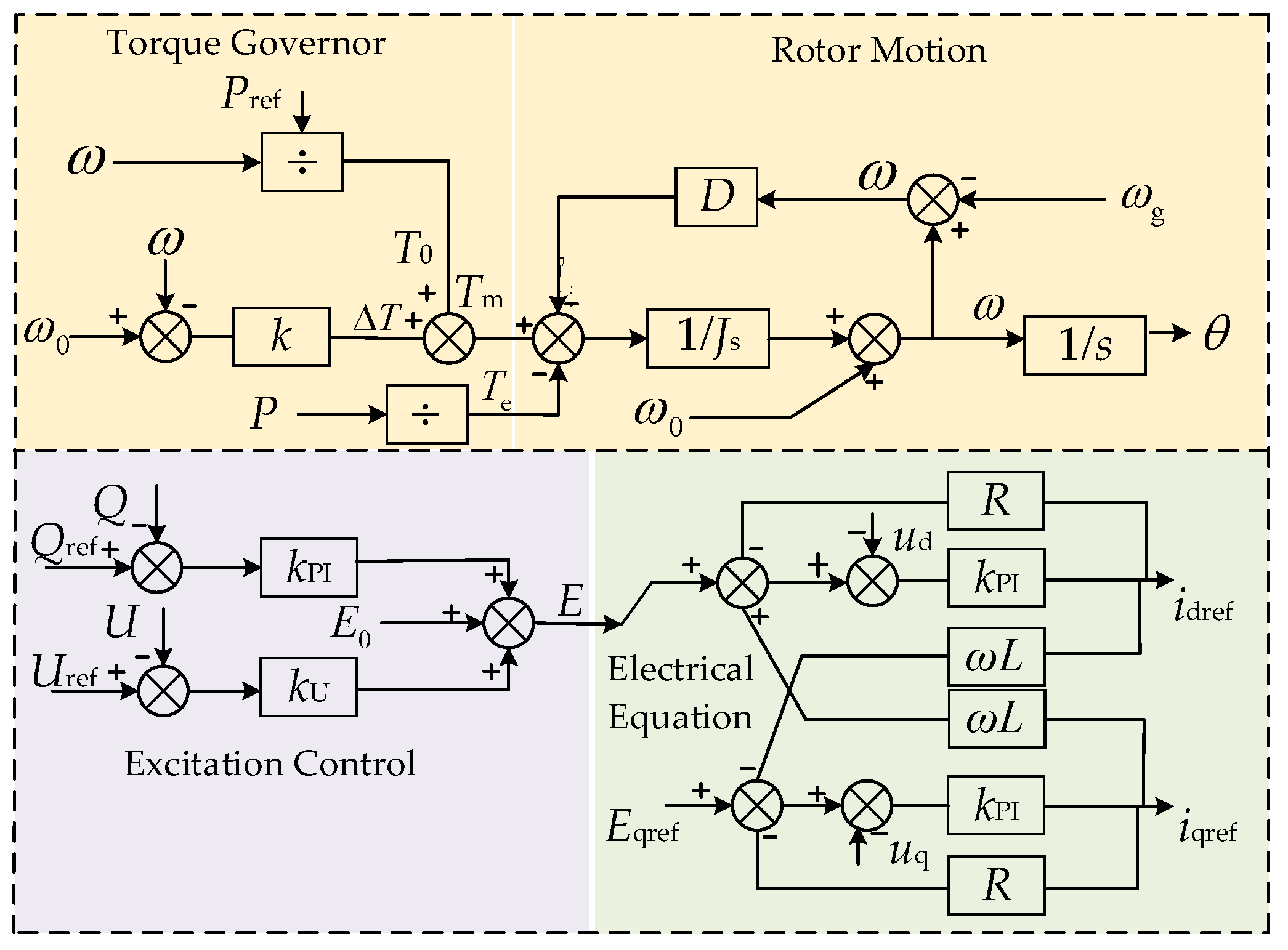
3.2. Design of VSG Controller
According to the VSG model in
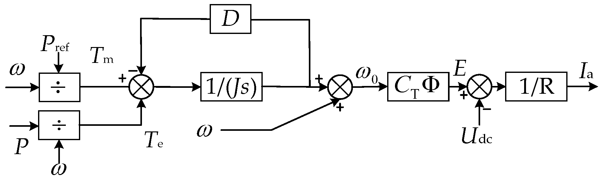
Section 3.1, the operating characteristics of the synchronous generator can be applied in the MMC power loop control, as shown in
Figure 4:
It can be seen from
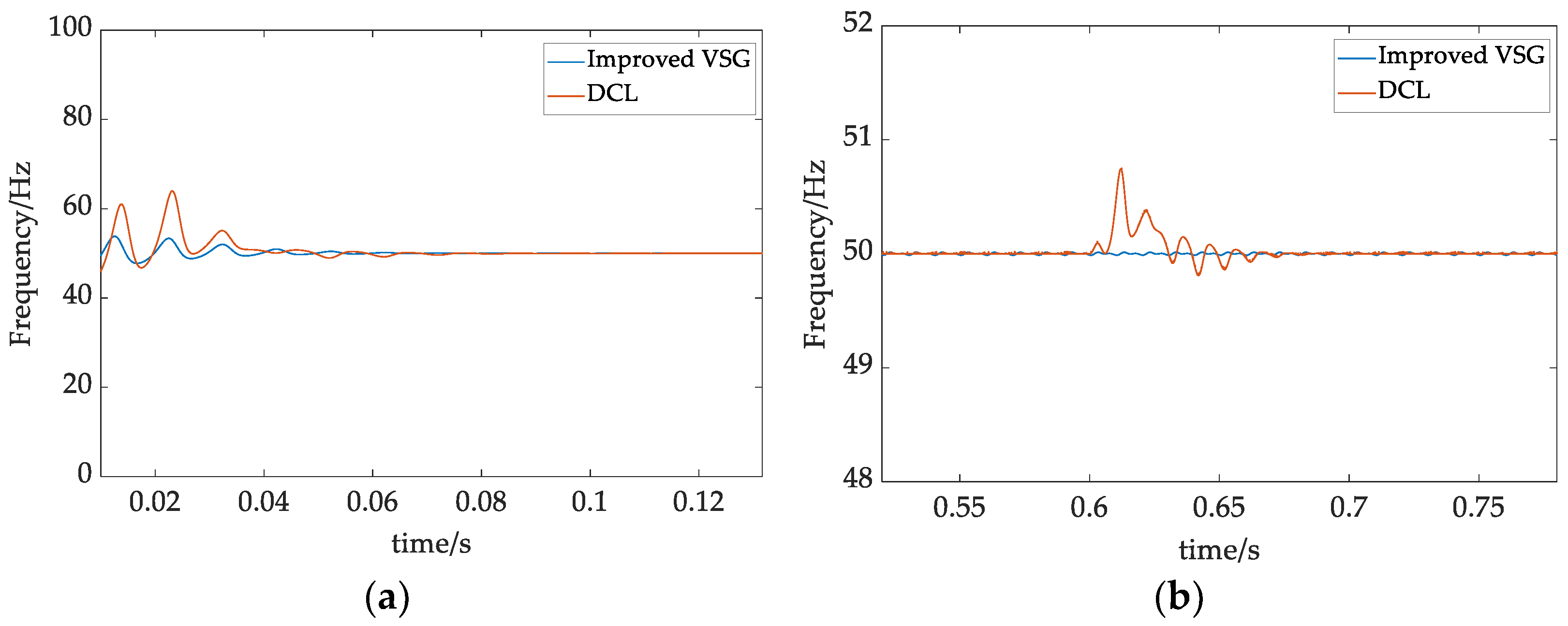
Figure 4, when there is a deviation between the output power and the expected power of the MMC-RPC, the power regulation can be realized by appropriately adjusting the torque increment. In this process, the kinetic energy stored by the rotor of the virtual synchronous generator makes the frequency of the system change slowly after being disturbed, and the support of inertia and damping makes the system more stable.
The excitation controller can adjust the reactive output of the generator according to the change of the generator terminal voltage; it can maintain the stability of the generator terminal voltage by controlling the excitation current and changing the induced electromotive force. When the voltage amplitude of the traction network changes, the reactive power compensation of the MMC-RPC system is realized by adjusting the excitation of its virtual synchronous motor; that is, changing the bridge arm voltage firstly, and then changing the output reactive power.
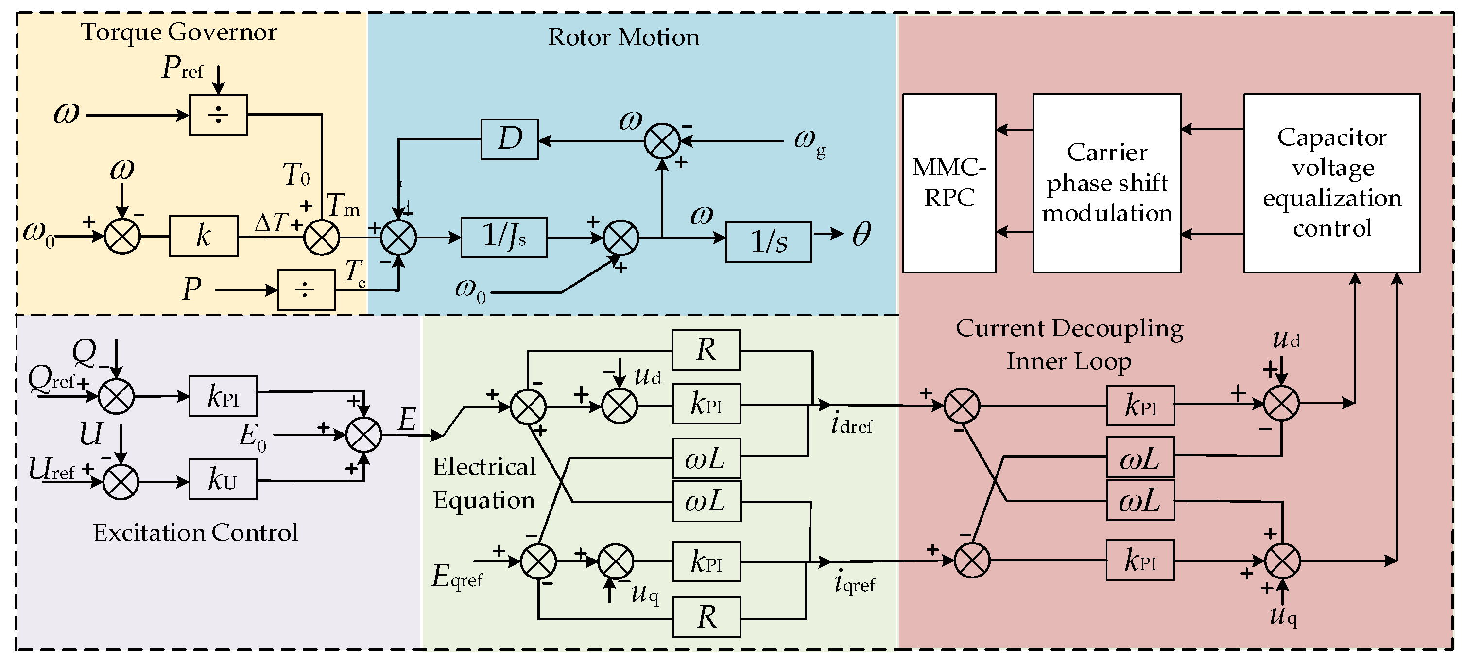
As shown in
Figure 5, the output electrical angle and potential of VSG are obtained through torque adjustment, rotor motion equation and excitation controller. Finally, the d-axis and q-axis components of VSG output current are used as the inputs of the stator electrical equation to obtain the expected value of current output. Then, through the dq axis current decoupling control, the voltage of each bridge leg of the MMC-RPC is constructed to obtain the start sequence of each submodule. Since the αβ axis component obtained by the controller through dq-αβ inverse transformation is a virtual quantity, it can be ignored.
3.3. Two-Stage Circulating Current Suppression Strategy
In the MMC-RPC system, the capacitor voltage balance control of the submodule can maintain the balance of capacitor voltage. However, the frequent charging and discharging of capacitors still make the voltage fluctuate, which leads to the instantaneous energy imbalance between the bridge arms and the double frequency circulation. And the circulating current will flow into the DC component, causing voltage and current fluctuations and reducing the reliability of the MMC [
28,
29]. Therefore, Quasi Proportional Complex Integral control (quasi-PCI, QPCI) and improved VSG stator electrical equation are established to suppress the circulating current in the system.
For the circulating current in the bridge legs of the MMC-RPC, QPCI controllers are used on both sides of the MMC to suppress it. QPCI has a better response speed than the Quasi Proportional Resonance control (quasi-PR, QPR), and it can maintain a higher accuracy in the case of frequency fluctuations.
The circulation current of bridge legs in MMC-RPC is [
28]:
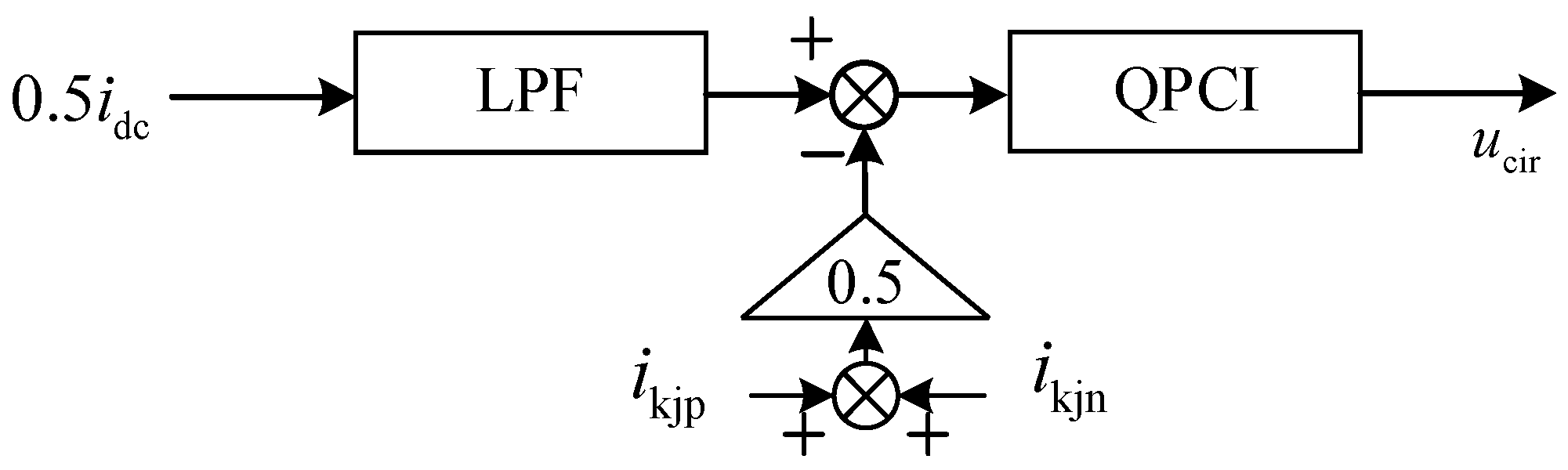
The transfer function of the QPCI controller is shown in Equation (17), and its control block diagram is shown in
Figure 6 [
26]:
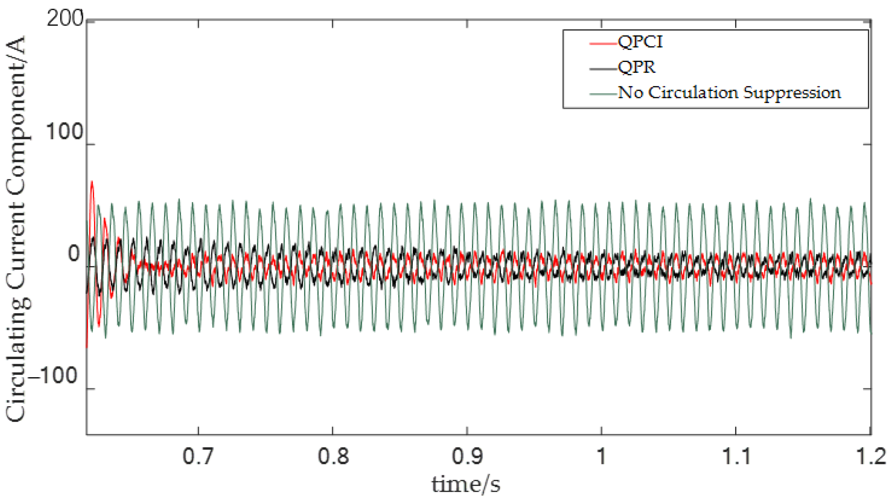
As shown in
Figure 7, when there is a large double frequency circulation at the bridge leg, the double frequency component between the bridge legs is quickly and fully suppressed after the circulation suppression control is put into operation. Among them, when QPR is put into operation at 0.65 s, circulation suppression is achieved at 0.75 s, while QPCI suppresses circulation at about 0.7 s. The adjustment time under QPCI is shorter.
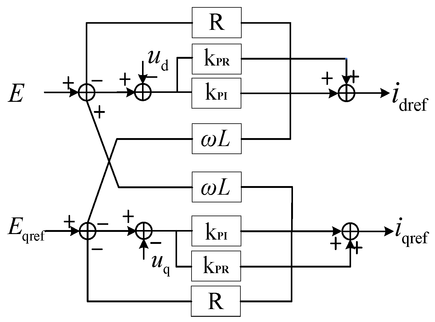
The output current is feedback to the input of the stator electrical equation module for the traditional VSG. When the load is unbalanced, the input current and the expected output value may have a double frequency AC component, aggravating the voltage imbalance. In this paper, a PI and QPR compound control strategy is applied to the stator electrical equation module of the VSG, to realize the accurate tracking of the DC component and the zero-error tracking of the AC component of double frequency.
The improved VSG control strategy is shown in
Figure 8:
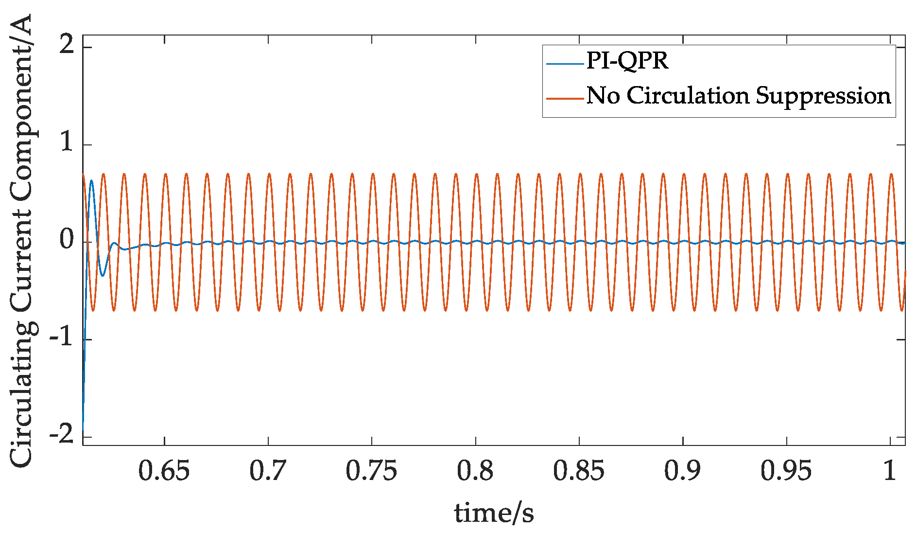
Figure 9 shows the suppression effect of the double frequency circulating current component in the QPR link of the stator electrical equation; it can be seen from the figure that the improved composite PI-QPR control can realize fast and effective suppression of the double frequency circulating current component compared with the unimproved VSG control.
3.4. Small Signal Analysis of VSG
VSG control has a good effect on improving the low inertia for power electronic converters. In order to observe the im-pact of control parameters on stability, small-signal modeling and analysis of the VSG control under small disturbance are carried out.
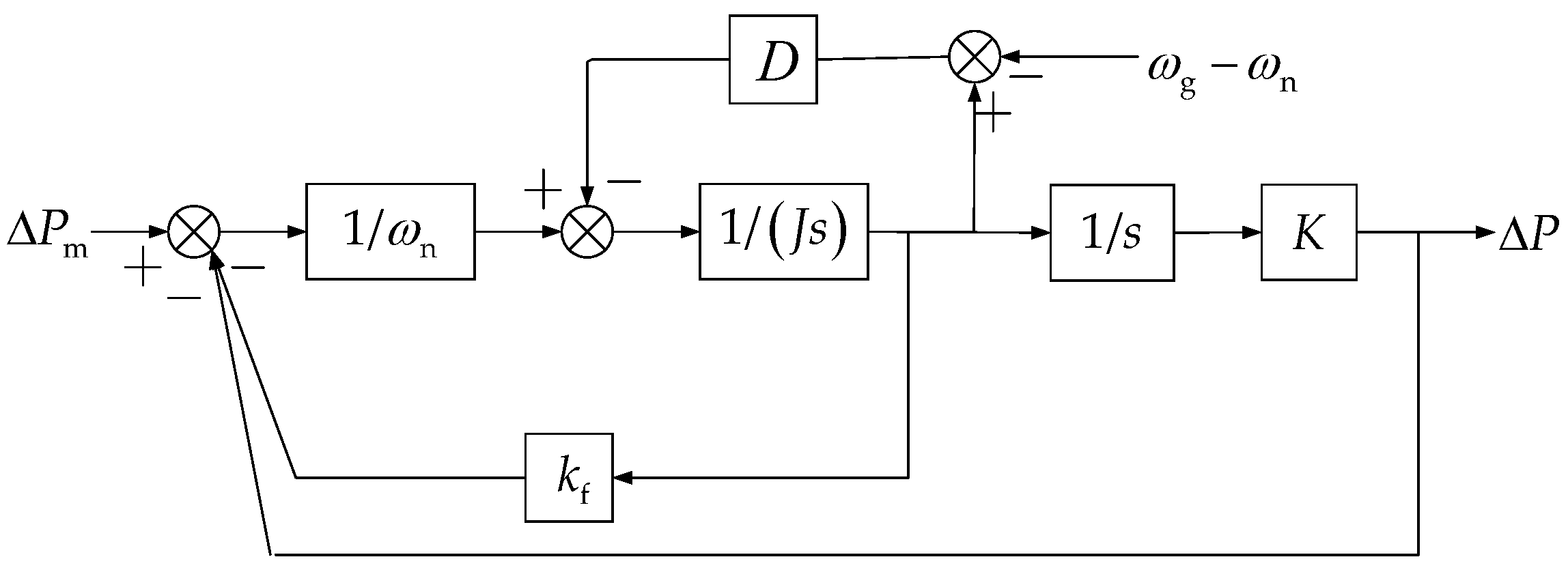
Figure 10 shows the VSG small signal analysis model, in which Δ
Pm is the input, and Δ
P is the output.
The small signal disturbance of VSG variables near the steady-state value is substituted into the VSG mathematical model, the steady-state quantity and the disturbance above the second order are omitted, and then the Laplace transform is carried out to obtain the following equations:
When the active power of VSG acts alone, the transfer function of VSG small signal analysis model can be obtained by combining with Equation (18):
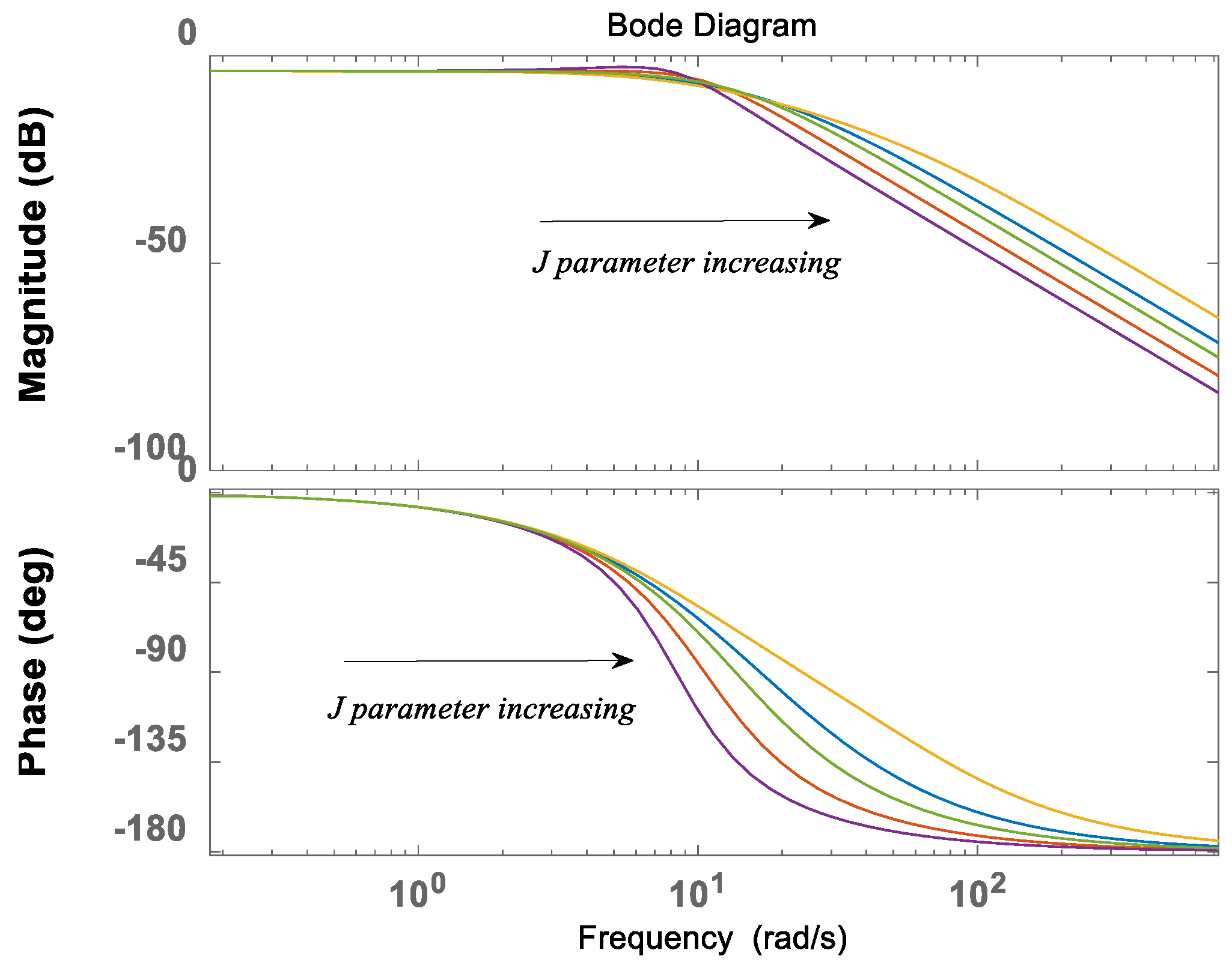
According to Equation (19) and its constraint equation, the Bode diagram of the active power transfer function is drawn. As shown in
Figure 11:
It can be seen that with the increase in the J parameter, margins of both magnitude-frequency and phase-frequency diagrams are becoming larger, showing better stability. However, if the inertia J is too large, the dynamic performance of the system will be degraded and the adjustment speed will be slowed down, which is not conducive to system stability.
According to
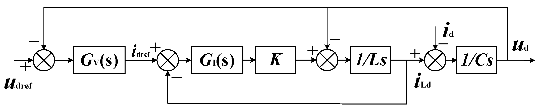
Section 3.2, an improved stator electrical equation is proposed in this study. The voltage outer loop adopts PI-QPR compound control, in which the PI controller is used to realize the error-free tracking of the DC component in the d-axis and q-axis voltage components, and the output current command is the DC component. QPR controller is used to realize the zero-error tracking of the double frequency AC component, and the output current command is the AC component. Since the dq axis component of the inductance current and the dq axis output current command by the voltage outer loop are the same in the steady state, the voltage loop output current command can be directly used as the current input of the stator electrical equation. Taking d axis as an example,
udref is the reference voltage of the d axis,
idref is the reference value of inductance current at the inverter side,
ud is the output voltage of the d axis,
id is the output current of d axis, and
iL_D is the feedback value of inductance current, as shown in
Figure 12 [
26].
In
Figure 12, the transfer function of PI control is [
26]:
where:
KP, KI are the proportional integral regulation parameters.
The transfer function of QPR controller is:
- 1.
ωc is the cut-off frequency of QPR;
- 2.
ωo is the resonant frequency.
As shown in
Figure 12, the open-loop transfer function under separate PI control is [
26]:
Combined with the above equation, the open-loop transfer function after adding QPR control is:
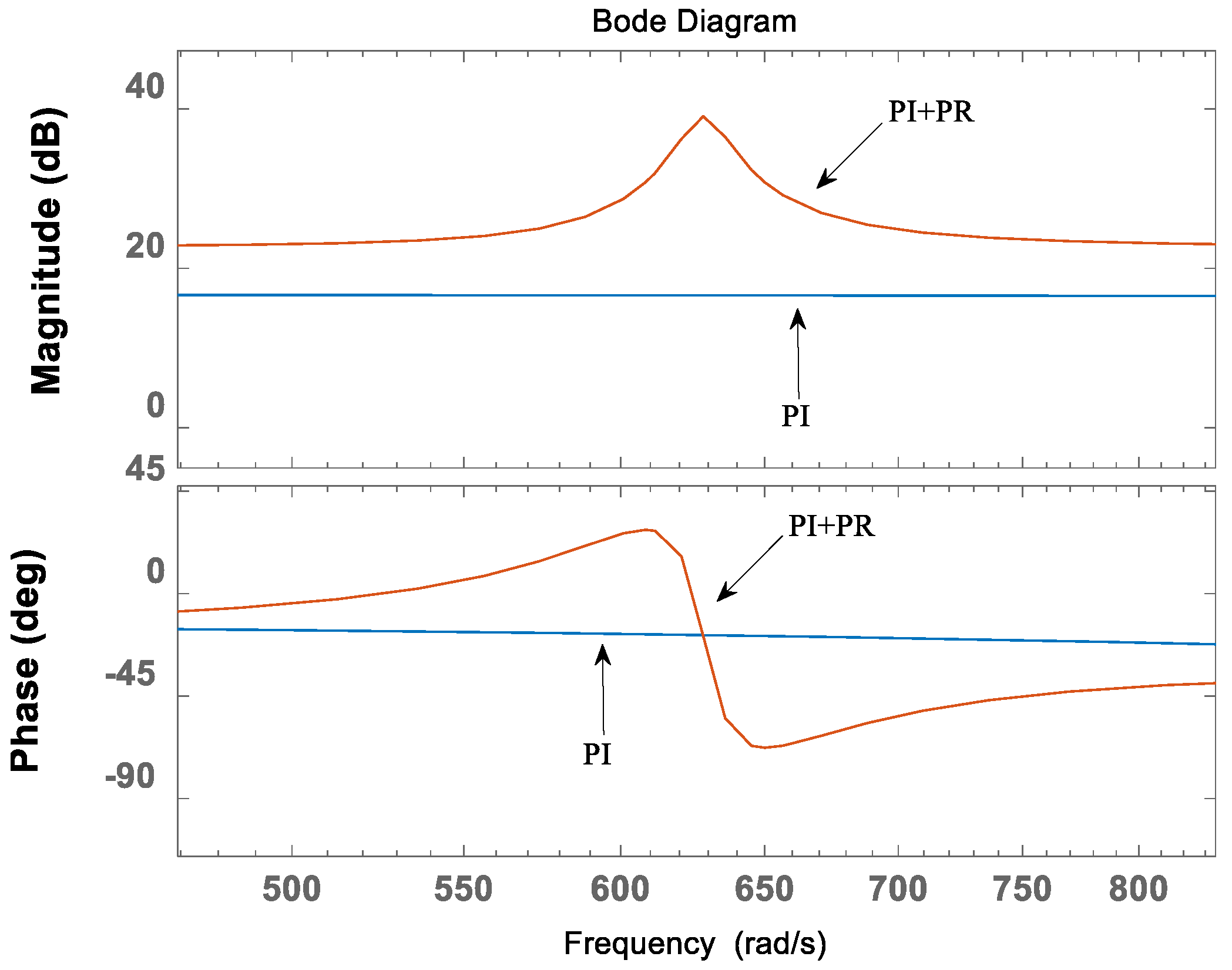
According to Equation (23), the Bode diagram of the open-loop transfer function corresponding to the PI controller and the PI and QPR composite controller can be drawn.
As shown in
Figure 13, under PI control, the dq axis output component of VSG is DC component. And the open-loop amplitude characteristic has infinite gain, which can realize the error-free control of dc component in dq axis. However, it cannot realize the error-free control of the double frequency circulating current component. With the QPR regulator, when the voltage component in the dq axis has double frequency fluctuation, the open-loop amplitude characteristic has infinite gain, which can realize the error-free control of the double frequency component in VSG. Therefore, the double frequency circulation is suppressed inside the VSG.
4. ES Type MMC-RPC
In order to utilize of regenerative braking energy in the high-speed railway system and improve the economy and stability of the system. ES type MMC-RPC has been applied, where SC units are distributed connected with submodules of the MMC-RPC, and they are controlled by the VDCM control.
As shown in
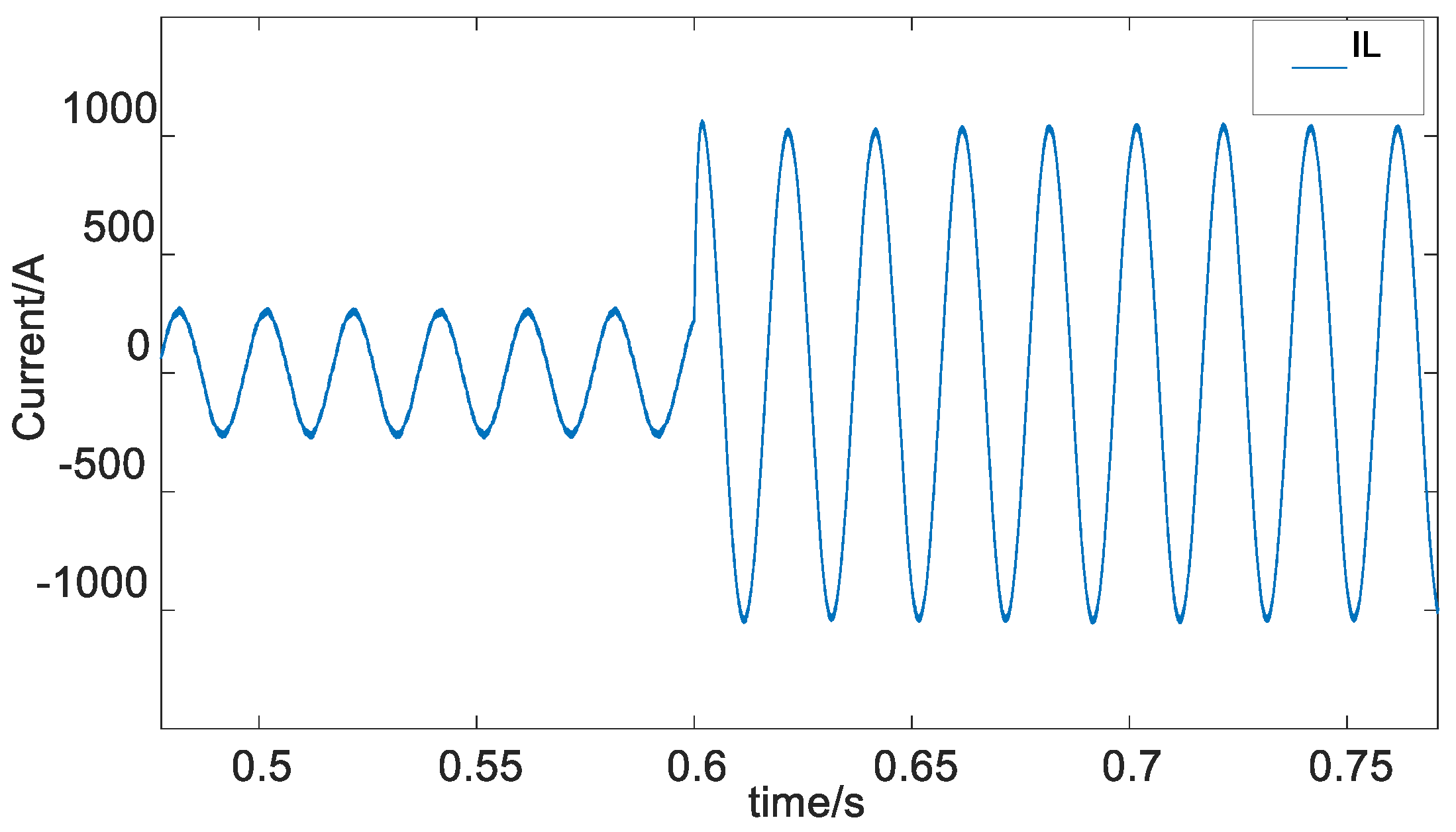
Figure 14, the SC-type ES units are connected in parallel to the DC-link capacitors of the submodules through DC/DC converters. The power flow among the DC links of the submodules. In the process of locomotive braking, the ES units absorb the regenerative braking energy, reducing its impact on the traction power supply system. During traction condition, SCs are discharged, thereby reducing the power supply requirement of the system.
The mechanical equation of the DC motor is [
22]:
where
- 1.
J is the moment of inertia of VDCM;
- 2.
Tm and Te are the mechanical torque and electromagnetic torque of VDCM, respectively;
- 3.
D is the damping coefficient.
The electrodynamic force balance equation of the armature circuit is:
where
- 1.
Φ is the torque coefficient of the DC motor;
- 2.
CT is the magnetic flux of each pole of the DC motor;
- 3.
ω is the angular speed of the DC motor.
The control method of the energy storage system is shown in
Figure 15:
By adjusting the input and output of the DC/DC converter, VDCM makes the converter have the characteristics of DC motor. The VDCM control block diagram is shown in
Figure 15. First, take the expected power
P as the mechanical power
Pm and the output power as the electromagnetic power
Pe. In the VDCM link, the inertia and damping characteristics of the DC motor are simulated according to the mechanical rotation Equation (24) and the armature loop electromotive force balance Equation (25). The duty cycle of the armature current
Ia is obtained through the current inner loop, and finally the control signal of the switch is obtained through PWM modulation.
6. Conclusions
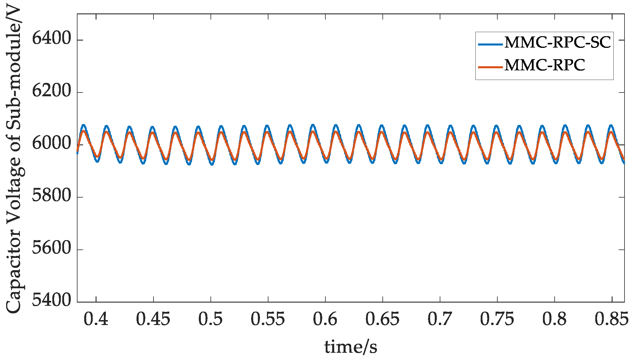
This paper proposes an ES type MMC-RPC, aiming at managing the power quality and regenerating braking energy for the V/v traction power supply system of the high-speed railway. This paper analyzes the mathematical model and control strategy of MMC-RPC, and proposes an improved VSG control strategy with two-stage circulating current suppression measures. Small signal analysis and simulation on Matlab/Simulink platform are carried out. The simulation results show that MMC-RPC can achieve good power quality management and energy utilization. Compared with DCL control, the VSG control proposed in this paper improves the stability of system frequency; compared with the traditional circulation suppression strategy, two-stage circulation suppression can better suppress the circulation of single-phase MMC. The research significance of this study also lies in the ES control of VDCM, keeping modular capacitor voltage stable while maintaining the capacitor voltage balance. Under the dynamic change of traction load, the stability and dynamics of ES type MMC-RPC can still be maintained.
However, this paper does not consider all application scenarios such as installing the equipment of MMC-RPC into the section posts of the traction power supply system other than the traction substations. We look forward to performing further research in the future, and the following conclusions are obtained:
- (1)
Quasi proportional complex integral (QPCI) control in the two-stage circulation suppression measures is used to suppress the circulation of the MMC bridge leg. The composite PI-QPR control is an improvement of the VSG strategy and suppresses the circulation inside VSG. The two-stage circulation suppression ensures the stable and effective operation of MMC-RPC based on VSG control.
- (2)
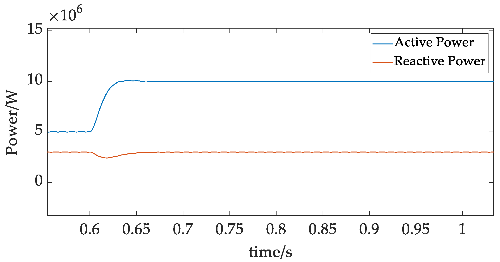
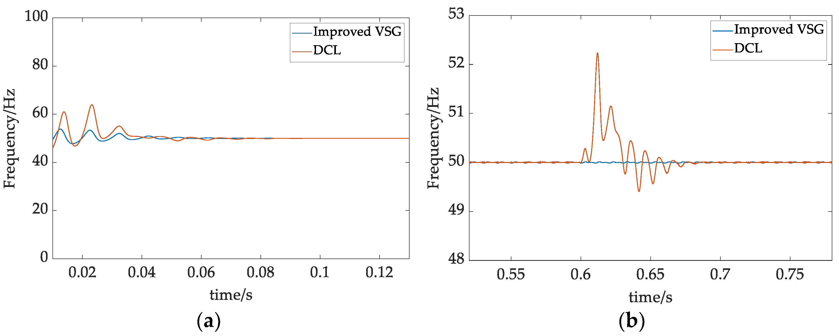
An energy storage-based MMC-RPC controlled by virtual motor is established. Compared with the traditional DCL power control, MMC-RPC under the improved VSG control, can improve the system stability and response speed of frequency and power in the case of a sudden change of traction load. When MMC is put into operation, it can achieve frequency stability faster. Through small signal analysis, the influence of damping parameters on the system is studied, and the stability of VSG control is verified. Under the improved VSG control, MMC-RPC system can better realize the comprehensive management of the power quality of the traction power supply system.
- (3)
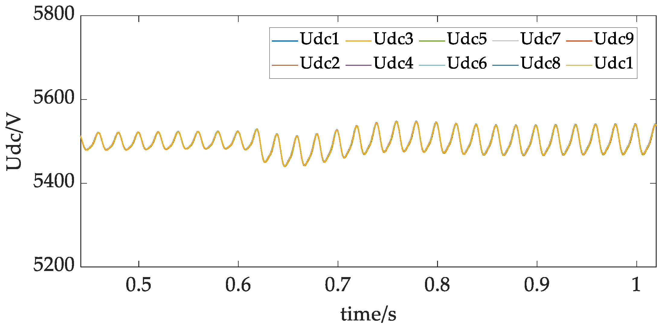
A distributed SC type ES scheme is proposed. And a VDCM control is adopted to realize the recovery and utilization of regenerative braking energy, to improve the economy of the railway system.
In the subsequent research, the application of hybrid energy storage in the MMC-RPC system will be further verified, and the corresponding experimental verification will be carried out.


