Article

Evaluation of Pt Deposition onto Dye-Sensitized NiO Photocathodes for Light-Driven Hydrogen Production

1
Department of Chemical, Pharmaceutical and Agricultural Sciences (DOCPAS), University of Ferrara, Via L. Borsari 46, 44121 Ferrara, Italy
2
Department of Chemical Sciences, University of Padova, Via F. Marzolo 1, 35131 Padova, Italy
3
Centro Interuniversitario per la Conversione Chimica dell’Energia Solare (SolarChem), Sez. di Ferrara, Via L. Borsari 46, 44121 Ferrara, Italy
*
Author to whom correspondence should be addressed.
Appl. Sci. 2022, 12(10), 4955; https://doi.org/10.3390/app12104955
Submission received: 29 April 2022 / Revised: 10 May 2022 / Accepted: 12 May 2022 / Published: 13 May 2022
(This article belongs to the Special Issue Redox- and Photoactive Functional Materials)

Abstract

:
The design of photocathodes for the hydrogen evolution reaction (HER), which suitably couple dye-sensitized p-type semiconductors and a hydrogen evolving catalyst (HEC), currently represents an important target in the quest for artificial photosynthesis. In the present manuscript, we report on a systematic evaluation of simple methods for the deposition of Pt metal onto dye-sensitized NiO electrodes. The standard P1 dye was taken as the chromophore of choice and two different NiO substrates were considered. Both potentiostatic and potentiodynamic procedures were evaluated either with or without the inclusion of an additional light bias. Photoelectrochemical characterization of the resulting electrodes in an aqueous solution at pH 4 showed that all the methods tested are effective to attain photocathodes for hydrogen production. The best performances (maximum photocurrent densities of −40 µA·cm−2, IPCE of 0.18%, and ~60% Faradaic yield) were achieved using appreciably fast, light-assisted deposition routes, which are associated with the growth of small Pt islands homogenously distributed on the sensitized NiO.

1. Introduction

The generation of molecular hydrogen through photochemical water splitting currently represents a fundamental reaction in the framework of sustainable development [1,2,3,4]. One of the possible approaches to target such a challenging process is represented by the dye-sensitized photoelectrochemical cell (DS-PEC). This device is ideally conceived as being comprised of two compartments, viz. a photocathode and a photoanode [5,6]. The former is based on a p-type semiconductor functionalized with a sensitizer and a hydrogen evolving catalyst (HEC), whereas the latter is composed of an n-type semiconductor, a chromophore unit, and an oxygen evolving catalyst (OEC).
The design of a tandem DS-PEC that incorporates both a photocathode and a photoanode necessitates the study and optimization of each single compartment. As far as the photocathodic side is concerned, its structural and functional role takes inspiration from that of dye-sensitized photocathodes employed in p-type dye-sensitized solar cells (p-DSSCs) [7,8,9]. In this respect, nanocrystalline NiO currently represents the standard material of choice for the design of photocathodes, and its coupling with photochemical and catalytic active components, particularly of a molecular nature, has been pursued to target photoelectrochemical hydrogen evolution [10]. As to the attachment of both active components onto the NiO surface, different approaches have been attempted to date, which include, among others, co-functionalization of NiO with separated dye/HEC units [11], use of molecular dyads [12], and layer-by-layer deposition of a sensitizer and a catalyst [13]. Quite unexpectedly, within this framework, the coupling of a dye-sensitized photoelectrode with material-based catalysts—potentially merging the tunability of the dye components with the efficiency and stability of solid-state catalysts—has rarely been considered [14,15].
We have recently reported on photoelectrochemical hydrogen evolution using photocathodes based on mesoporous NiO, CdTe/CdS quantum dots as sensitizers and either a molecular nickel complex or heterogeneous platinum as the HEC [16]. In the latter case, attachment of the Pt HEC was performed through a simple photoelectrodeposition method. Interestingly, the photoelectrochemical performance of the resulting photoelectrodes was observed to be largely affected by the deposition time and conditions. Since no systematic evaluation of Pt deposition onto sensitized NiO electrodes has been attempted so far, we decided to perform a detailed investigation on the effects of the deposition conditions on the hydrogen evolving reaction (HER) promoted at a NiO photocathode. In order to make this study as general as possible, we considered direct Pt deposition onto mesoporous NiO sensitized with the standard P1 dye (Figure 1), a reference organic compound used in p-DSSCs and whose photochemical behavior on NiO is rather well-established [17,18,19]. We also employed two mesoporous NiO substrates prepared via different procedures in order to evaluate potential effects from the semiconducting support as well as the possible generalization of the methodology presented here. The results highlight that the best photoelectrochemical performances can be achieved using appreciably fast deposition methods that couple both light and potential bias.

2. Materials and Methods

2.1. Apparatus and Procedures

All reagents were purchased from Sigma Aldrich (St. Louis, MO, USA) and used as received. Milli-Q water was obtained using a Millipore (Burlington, MA, USA) apparatus, equipped with 0.22 µm filters. TEC 8 Fluorine-doped Tin Oxide (FTO) conductive glass slides were purchased from Pilkington (Lathom, UK).
UV-Vis absorption spectra were measured with an Agilent Technologies Cary 300 spectrophotometer (Santa Clara, CA, USA). SEM micrographs and EDS analysis were obtained using an FE-SEM Jeol JSM 7600f scanning electron microscope with an accelerating voltage of 15 kV. Atomic force microscopy (AFM) images were collected using a Digital Instruments Nanoscope III scanning probe microscope (Digital Instruments, Santa Barbara, CA, USA). The instrument was equipped with a silicon tip (RTESP-300 Bruker, Billerica, MA, USA) and operated in tapping mode. Surface topographical analysis of raw AFM images was carried out with both Nanoscope 1.5 and Gwyddion analysis software. The film thickness was measured using an Alpha Step D-500 Profilometer (KLA instruments, Milipitas, CA, USA). Data were obtained in step-up/down mode with a scan length of 2 mm at a speed of 0.07 mm·s−1 and a stylus force of 5.0 mg. Photoelectrochemical measurements were carried out on a PGSTAT 302N potentiostat in a three-electrode configuration, using an SCE and a Pt wire as the reference and the counter electrode, respectively. A LOT-Oriel solar simulator, equipped with an AM 1.5 G filter, was used as the illumination source and set to 0.1 W∙cm−2 power irradiance by means of a power meter (Newport 1918-C). Current–voltage and chronoamperometry curves under shuttered illumination were acquired by manually chopping the excitation source. IPCE was measured in a three-electrode configuration under the monochromatic illumination generated by an air-cooled Luxtel 175 W Xe lamp coupled to an Applied Photophysics monochromator. The photocurrent, recorded at the constant potential of −0.2 V vs. SCE, was acquired on an Eco Chemie PGSAT 101 Potentiostat. Incident irradiance was measured with a calibrated silicon photodiode. Determination of the Faradaic efficiency (FE) was performed through a generator–collector method, adapted from the literature [20]. Briefly, the photocathode was illuminated under an applied bias, thus acting as a H2 generator. A Pt-covered FTO electrode, prepared by doctor blading of a 5 mM H2PtCl6 solution in ethanol (with 37.5 mg·mL−1 of ethyl cellulose as a thickener) followed by calcination at 500 °C for 15 min, was sandwiched onto the photocathode and used as the collector, i.e., the electrode at which the oxidation of the evolved H2 takes place. The sandwiched device was held together by a layer of unstretched parafilm (ca. 200 µm spacing), sealed under pressure at 60 °C for 50 s. The parafilm was designedly cut to form an L-shaped chamber to minimize H2 loss while still allowing for the electrolyte to access by capillary forces. Both the photocathode generator and the FTO-Pt collector were contacted using Cu tape and connected to the two working electrodes of a bipotentiostat (PGSTAT 30), while an SCE and a Pt wire were used as the reference and the counter electrode, respectively. The generator electrode was held at a bias of −0.2 V vs. SCE, while the collector was biased at +0.2 V vs. SCE, which was identified as the optimum H2 oxidation potential (controlled by bubbling H2 gas in aqueous solution).

2.2. Preparation of Photoelectrodes

FTO cleaning was performed by sonicating the slides in Alconox® solution for 10 min and in 2-propanol for an additional 10 min. NiO electrodes of type A were prepared by spin coating onto FTO electrodes (10 s at 1000 rpm, 20 s at 2000 rpm) of the NiO paste obtained by ball-milling (2 h) of commercially available NiO nanoparticles (Inframat Advanced Materials) with ethanol (8 mL), glacial acetic acid (0.2 mL), terpineol (3 g), and ethyl cellulose (0.5 g) [19]. NiO electrodes of type B were prepared by doctor blading of a NiO precursor solution prepared by dissolving NiCl2 (1 g) and the tri-block co-polymer F108 (1 g) in ethanol (6 g) and water (5 g) [21]. For both types A and B, the electrodes were annealed at 550 °C following a programmed temperature ramping: 25–120 °C (10 min), 120 °C (0 min), 120–450 °C (22 min), 450 °C (30 min), 450–550 °C (10 min), 550 °C (20 min). Sensitized electrodes were obtained by overnight soaking of the NiO films in 0.5 mM P1 in acetonitrile solution. Platinum was deposited onto the sensitized electrodes from a precursor solution prepared following a reported procedure [22]. Briefly, a solution of aqueous 0.1 M H2PtCl6 in 0.1 M HCl was prepared; the resulting solution was first neutralized using Na2CO3 and then adjusted to pH 4 with glacial acetic acid. Before the deposition, all NiO electrodes were tested against the photoreduction of 10 mM [Co(NH3)5Cl]Cl2 as a sacrificial electron acceptor [16,23]. Only when the maximum photocurrent densities in the order of 250–300 μA∙cm−2 were measured, the NiO electrodes, of both types A and B, were considered and thus employed for the Pt deposition (see Figures S1 and S2). Deposition of metallic Pt was achieved through five different methodologies: Method 1 involved illumination with a solar simulator (0.1 W∙cm−2) under the application of a −0.2 V vs. SCE voltage bias. Method 2 involved the sole application of a −0.2 V vs. SCE voltage bias. Method 3 employed 3 consecutive cyclic voltammetry scans from 0.3 to −0.2 V vs. SCE at a scan rate of 0.1 V∙s−1 under illumination with a solar simulator (0.1 W∙cm−2). Method 4 involved 3 consecutive cyclic voltammetry scans from 0.3 to −0.2 V vs. SCE at a scan rate of 0.1 V∙s−1 without illumination. Method 5 employed 3 consecutive cyclic voltammetry scans from 0.3 to −0.2 V vs. SCE at a scan rate of 0.1 V∙s−1 and 2 s illumination with a solar simulator (0.1 W∙cm−2) during the first return scan from −0.2 to 0 V vs. SCE.

3. Results and Discussion

3.1. Preparation of the Electrodes and Characterization

Photocathodes based on nanocrystalline NiO were prepared according to procedures adapted from the literature [19]. Two different methodologies were employed, leading to NiO electrodes of type A and type B. For NiO electrodes of type A, a NiO paste made of pre-formed NiO nanoparticles was employed and deposited by spin coating onto FTO electrodes, while for NiO electrodes of type B, a precursor solution based on NiCl2 was used, which was deposited onto FTO by doctor blading (see Section 2.2). In both cases, calcination at 550 °C following a programmed ramping procedure was performed to attain the desired NiO electrodes. Film thickness was measured using a profilometer and found to be 1.1 and 0.6 μm for electrodes of types A and B, respectively (
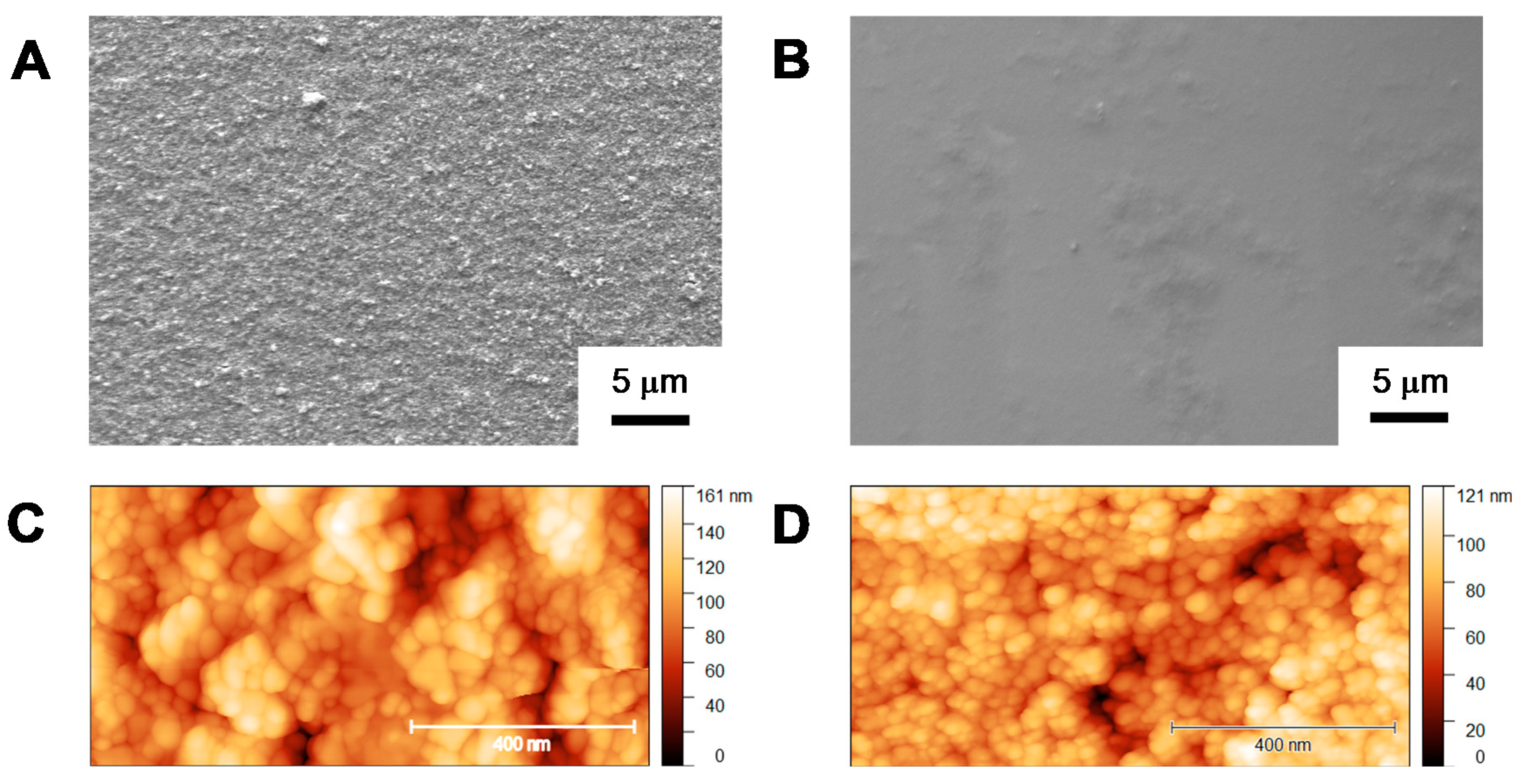
Figure S3). The morphology of the NiO films was then characterized by SEM and AFM analyses. Representative SEM micrographs and the corresponding AFM images are shown in Figure 2.
For both electrode types, the SEM analysis shows a homogeneous distribution of the nanocrystalline NiO support onto the FTO substrate. The surface is, however, more porous and rougher for NiO electrodes of type A (Figure 2A) with respect to NiO electrodes of type B, for which a flatter structure is clearly apparent (Figure 2B). Both AFM images (Figure 2C,D) and the corresponding section analyses (Figure S4) further confirm these observations. Increased surface roughness was indeed measured for electrodes of type A (Rq = 48.4 nm, Ra = 40.9 nm) when compared to electrodes of type B (Rq = 13.7 nm, Ra = 10.6 nm). These data agree with the higher porosity, as measured by gas adsorption isotherms, and the smaller crystallite size, as measured by X-ray diffraction (XRD) analysis, expected for NiO electrodes of type A rather than those of type B [19]. Finally, the AFM analysis (Figure 2C,D and Figure S4) suggests improved connectivity among NiO nanoparticles in the case of electrodes of type A.
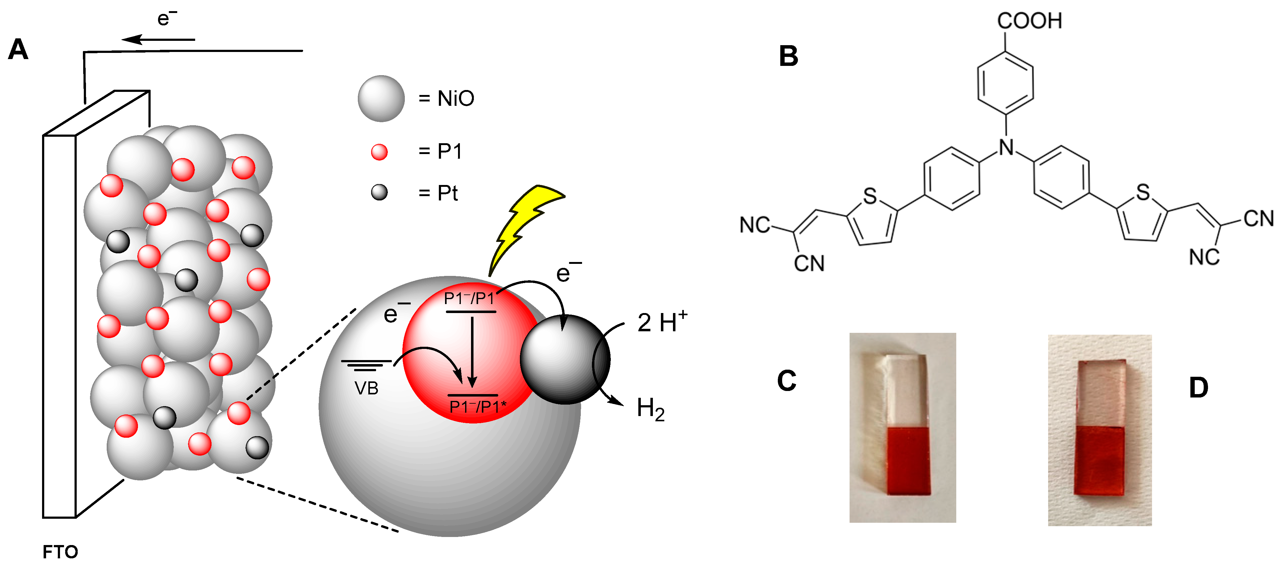
The NiO films were then sensitized by overnight soaking into a 0.5 mM solution of 4-(bis-{4-[5-(2,2-dicyano-vinyl)-thiophene-2-yl]-phenyl}-amino)-benzoic acid (P1) in acetonitrile. Two exemplars of the resulting electrodes are reported in Figure 1C,D. Since electrodes of type A are not sufficiently transparent to enable reliable measurement of the absorption spectrum using spectrophotometry in transmission mode, determination of the dye loading was attained through a desorption procedure performed by treating a sensitized electrode with tetrabutylammonium hydroxide (TBAOH) in methanol followed by registration of the absorption spectrum (see Supplementary Materials, Figure S5). Then, considering the molar extinction coefficient of the P1 dye in acetonitrile at the absorption maximum (ε = 58,000 M−1cm−1) [17] and assuming similar ε values for the protonated and deprotonated species, the amount of dye was quantified using the Lambert–Beer equation. A surface concentration of 11.7 (±1.7) nmol∙cm−2 was estimated for sensitized NiO electrodes of type A. On the other hand, determination of the dye loading for sensitized electrodes of type B was possible by direct measurement of the absorption spectrum (Figure S6). Using the Lambert–Beer equation for thin films (Equation (1)) and considering the maximum absorption and the extinction coefficient [17], a surface loading of 6.9 (±0.3) nmol∙cm−2 was calculated. This result was further confirmed by desorption measurements with TBAOH in methanol (surface concentration of 6.7 (±0.9) nmol∙cm−2, Figure S7). The larger dye loading observed for NiO electrodes of type A can be attributed to the higher porosity of the NiO film as well as to the larger film thickness, both leading to an increased surface area for attachment of the P1 dye.
A = Γ · ε · 1000
Deposition of heterogeneous Pt was performed on sensitized NiO electrodes immersed in the platinizing solution based on H2PtCl6 as the metal precursor [22] using simple and fast procedures upon application of a potential bias or a combination of both potential and light biases. Five different methodologies were considered. In Methods 1 and 2, a stationary potential of −0.2 V vs. SCE was applied, either coupled or not to light irradiation, and different time intervals were considered. Under these conditions, Pt deposition implies the reduction of Pt(IV) to Pt(0), most likely occurring through the transient formation of a Pt(II) species [24]. The typical current vs. time responses obtained using Methods 1 and 2 are reported in the Supplementary Materials (Figure S8). Both feature an increase in cathodic current, ascribable to nucleation and progressive growth of Pt onto the sensitized NiO surface, until reaching a plateau associated with deposition conditions limited by diffusion of Pt(IV) to the electrode surface [25]. Interestingly, the rates to achieve such plateau currents are different for the two methods, suggesting that the nucleation and growth of Pt islands onto sensitized NiO might differ to some extent when the photoexcited dye can mediate the reduction of Pt(IV) ions as in Method 1 (i.e., under irradiation conditions after hole injection into the NiO valence band) or not (i.e., under dark conditions, Method 2). Following the suggestions in the literature [26], we also employed potentiodynamic conditions for Pt attachment onto our sensitized NiO electrodes (Methods 3–5). Three cycles of cyclic voltammetry spanning the potential range between +0.3 and −0.2 V vs. SCE at a scan rate of 0.1 V·s−1 were considered, either coupled or not to light irradiation (see Section 2.2). We envisioned that the application of the negative potential enabling the reduction of Pt(IV) will promote the nucleation of Pt metal onto the surface, while the subsequent anodic scan will renew the Pt(IV) electrolyte solution close to the electrode, thus potentially favoring a cleaner deposition upon the subsequent cathodic scan. The current vs. voltage traces recorded during the platinization process of sensitized NiO electrodes of type A are reported in the Supplementary Materials (Figures S9–S11). An increase in cathodic current was observed in the presence of the light bias, possibly due to the active participation of the P1 dye in the deposition event [14]. Interestingly, a noticeable current enhancement was also observed at negative potentials, regardless of the method used, in the second and third scans, which can be attributed to progressive, favorable growth of Pt islands following kinetically limited nucleation at the first cathodic scan [26].
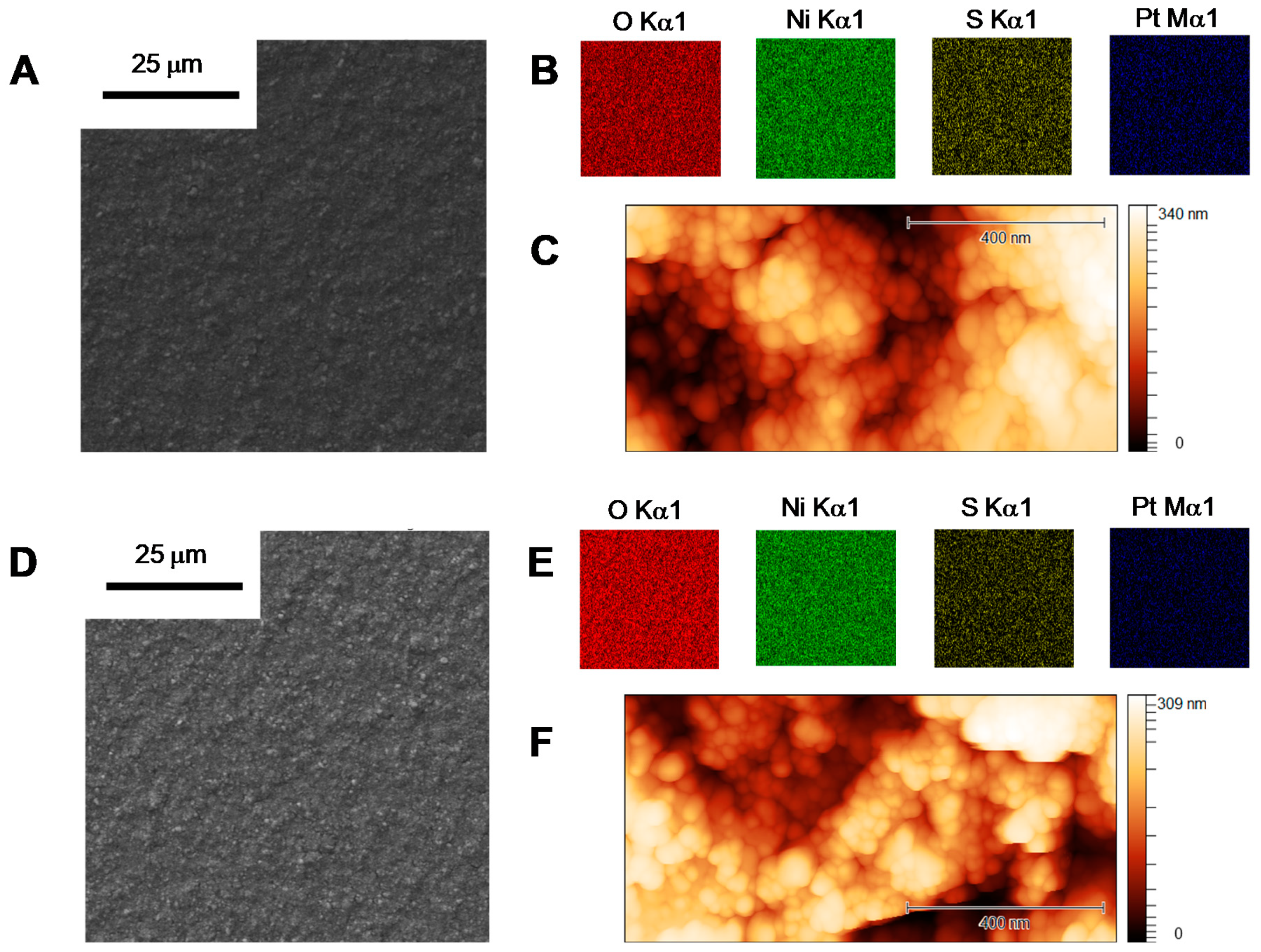
Combined SEM/EDS and AFM analyses were employed to characterize exemplars of sensitized and platinized NiO electrodes. Figure 3 depicts the data for two electrodes of type A obtained via photoelectrodeposition, viz. Method 1 with a deposition time of 20 s and Method 5, whereas the results for an exemplar prepared via the dark Method 2 are reported in the Supplementary Materials (Figure S12). For all the samples tested, the observation of characteristic S and Pt emissions in the EDS maps clearly confirms the simultaneous presence of both the P1 dye and the Pt HEC, respectively. Furthermore, both the EDS and AFM analyses suggest that regardless of the deposition method, the distribution of the Pt metal is rather homogenous, supporting preferential formation onto the sensitized NiO surface of small, well-distributed Pt islands over large metal clusters. The failure to observe, at the current size resolution, appreciably different morphological features in the case of light vs. dark conditions possibly suggests that such differences are, if at all present, intrinsically small.

3.2. Photoelectrochemical Characterization

The NiO photoelectrodes functionalized with both P1 dye and the Pt HEC, according to the procedures previously discussed, were tested by means of linear sweep voltammetry (LSV) and chronoamperometry (CA) under chopped light irradiation (calibrated at 1 sun) in N2-purged 0.1 M acetate buffer at pH 4. The associated maximum photocurrent density, viz. the maximum difference between the measured current density in the presence of light subtracted by that in the absence of light, was then extracted as a figure of merit for comparison purposes (see the estimate for an exemplar in Figure S13). The experimental conditions were fixed because at a more acidic pH, rapid discoloration of the electrode was observed, ascribed to substantial desorption of the P1 dye from the NiO surface, while at a higher pH, the resulting photocurrents were considerably smaller than those measured here, thus preventing a reliable evaluation of the different deposition methodologies. Furthermore, since we aimed for a fast screening of the deposition methodology, the CA measurements were limited to a time window of 5 min. 
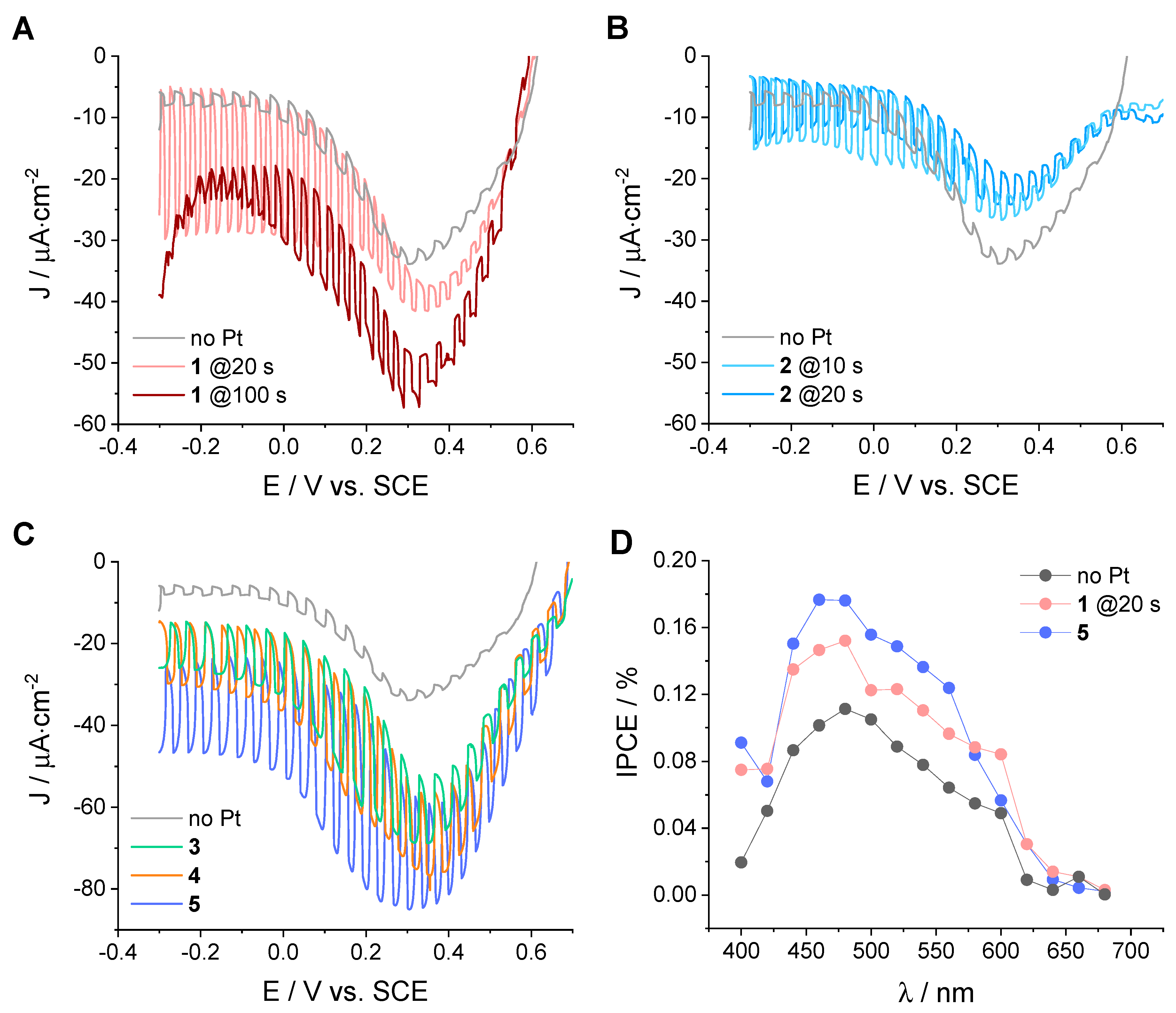
Figure 4 shows the relevant LSV curves recorded for the sensitized and platinized NiO photoelectrodes of type A. As can be clearly seen, all platinization procedures, regardless of their nature, yielded active photocathodes with measured photocurrent densities featuring onset potentials between 0.4 and 0.7 V vs. SCE and values well above those of sensitized NiO without Pt. This experimental evidence can be taken as a clear indication that all functionalized electrodes can effectively promote electron transfer processes to the electrolyte mediated by the Pt metal on the surface. In particular, the observed improved photocurrents can be ascribed to the occurrence of photoinduced electron transfer processes involving hole injection from the excited state of the P1 dye (*P1) into the valence band (VB) of NiO, followed by electron transfer from the reduced form of the dye (P1) to the Pt HEC that mediates proton reduction to dihydrogen (Figure 1A). More importantly, the measured photocurrent densities appreciably depend on the procedure employed for the attachment of the catalytic metal.
For electrodes prepared using Method 1 (hereafter named NiO-A|P1|Pt-1; see Figure 4A for two relevant exemplars and Figure S14 for the whole series), the maximum photocurrent densities achieved were also affected by the deposition time: −15 µA·cm−2 at 10 s, −25 µA·cm−2 at 20 s, −15 µA·cm−2 at 30 s, −18 µA·cm−2 at 50 s, and −13 µA·cm−2 at 100 s. Interestingly, the largest values were attained at short to intermediate deposition times (i.e., 20 s), most likely resulting as the best balance in terms of catalyst loading. A similar effect was already observed in our previous study using CdTe/CdS quantum dots as sensitizers [16]. A large catalyst loading for NiO-A|P1|Pt-1 electrodes at longer deposition times (see, e.g., 100 s in Figure 4A) was further confirmed by the noticeable increase in cathodic dark current, likely ascribable to direct electrocatalysis by Pt. The trend in photocurrent densities for the different deposition times was also maintained when the electrodes were probed by CA at −0.2 V vs. SCE (Figure S15), although the steady-state photocurrent values measured were lower. Interestingly, the samples prepared at longer photoelectrodeposition times (>30 s) showed rapidly decreasing photocurrents attributable to charge recombination processes, most likely determined by the presence of large amounts of Pt HEC on the electrode surface.
Method 2, which differs from Method 1 in the absence of the light bias, was also employed for the preparation of NiO photocathodes (hereafter named NiO-A|P1|Pt-2). Previous studies that employed Method 2 as a platinization procedure usually considered long deposition times (>300 s) [27,28]. Attempts at preparing NiO-A|P1|Pt-2 electrodes with such deposition times were, however, unsuccessful, as negligible photocurrent densities, close to those of the blank sample, as well as considerable dark currents, ascribed to direct electrocatalysis by Pt, were measured. Shorter deposition times, similar to those employed in Method 1, were thus considered. These electrodes systematically performed worse than those obtained with Method 1, leading to maximum photocurrent densities of −10 µA·cm−2 at 10 s and −12 µA·cm−2 at 20 s as measured by LSV under chopped irradiation (Figure 4B). This suggests that the coupling of both light and electrochemical potential is important to favor effective Pt deposition onto sensitized NiO electrodes. A similar trend was observed also in the CA measurements (Figure S16 of the Supplementary Materials).
The best results obtained using both Methods 1 and 2 at short deposition times clearly evidence the necessity of having a small amount of catalytic Pt metal on the sensitized NiO surface. Large amounts of catalyst may indeed play the role of recombination centers, thus decreasing the possibility of profitably converting photogenerated electrons into molecular hydrogen [25,29]. In this respect, we envisioned that the application of an inherently fast procedure such as cyclic voltammetry might well comply with this important requirement. As a matter of fact, the potentiodynamic deposition methods (Methods 3–5) turned out to be effective for the platinization of sensitized NiO electrodes, with performances that depended on the presence and duration of the light bias. Figure 4C shows the LSV traces obtained under chopped irradiation of electrodes prepared according to Methods 3–5 (hereafter named NiO-A|P1|Pt-3, NiO-A|P1|Pt-4, and NiO-A|P1|Pt-5, respectively), whereas in Figure S17, the corresponding CA traces recorded at −0.2 V vs. SCE are reported. Maximum photocurrent densities in the order of −29, −27, and −40 µA·cm−2 were measured for the NiO-A|P1|Pt-3, NiO-A|P1|Pt-4, and NiO-A|P1|Pt-5 electrodes, respectively. According to these data, Method 5, which combines a CV scan and a short illumination, provides the most active photocathodes. Although the SEM/EDS analysis suggests a similar distribution of the Pt HEC onto the sensitized NiO surface, the beneficial effect of including light irradiation under both potentiostatic and potentiodynamic conditions is clearly apparent. The resulting improvement most likely stems from subtle structural arrangements as well as NiO/dye/catalyst interactions that might differ when the P1 dye takes an active part (as in Methods 1, 3, and 5) or does not (as in Methods 2 and 4) in the reduction of the Pt(IV) electrolyte and the nucleation of Pt.
The NiO electrodes obtained via the best deposition procedures among the potentiostatic and potentiodynamic methods (viz. NiO-A|P1|Pt-1 at 20 s and NiO-A|P1|Pt-5) were further characterized to gain additional insight into the photoelectrochemical performances. We first checked if the observed photocurrent enhancements were assignable to hydrogen generation by determining the Faradaic efficiency (FE) using a generator–collector method adapted from the literature [20]. Hydrogen was produced with FEs of 38 (±2)% and 60 (±5)% for NiO-A|P1|Pt-1 at 20 s and NiO-A|P1|Pt-5, respectively (Figures S18 and S19), which substantially surmount the negligible FE measured in the absence of the Pt HEC (3 (±2)%, Figure S20). These data clearly confirm that the improvement in terms of photocurrent densities can be unambiguously assigned to profitable charge transfer to the aqueous electrolyte involving proton reduction to dihydrogen mediated by the Pt HEC, as previously inferred. The photoaction spectra of both NiO-A|P1|Pt-1 at 20 s and NiO-A|P1|Pt-5 were then determined and compared with that of the sensitized NiO electrode without Pt HEC (Figure 4D). For all samples tested, the photoaction spectrum closely resembled the absorption spectrum of the P1 dye [17], thus confirming that in all cases, the photoelectrochemical response is triggered by light absorption by the molecular chromophore. More interestingly, higher efficiencies were measured in the platinized electrodes, with maximum incident photon-to-current conversion efficiency (IPCE) values of 0.15% and 0.18% for NiO-A|P1|Pt-1 at 20 s and NiO-A|P1|Pt-5, respectively. Taking Equation (2) and considering a light-harvesting efficiency (LHE) of ~0.8 at the absorption maximum—as possibly estimated according to Equations (1) and (3) considering the surface concentration of P1 dye previously calculated (~11.7 nmol·cm−2) and the molar extinction coefficient at the absorption maximum (ε = 58,000 M−1cm−1) [17]—these data correspond to absorbed photon-to-current conversion efficiency (APCE) values of 0.187% and 0.225% for NiO-A|P1|Pt-1 at 20 s and NiO-A|P1|Pt-5, respectively. According to Equation (2) and the almost unitary yield of hole injection (Φinj) by the P1 dye into NiO (~97%) [30], charge collection efficiencies (ηcc) of 0.19% and 0.23% can be estimated for NiO-A|P1|Pt-1 at 20 s and NiO-A|P1|Pt-5, respectively.
APCE = IPCE ( λ ) / LHE ( λ ) = Φ i n j · η c c
LHE ( λ ) = 1 10 A ( λ )
The same platinization procedures used for electrodes of type A were employed for the attachment of the Pt HEC onto NiO electrodes of type B sensitized with the P1 dye (hereafter named NiO-B|P1|Pt-n, where n = 1–5) in order to evaluate the potential general applicability of our deposition methods. 
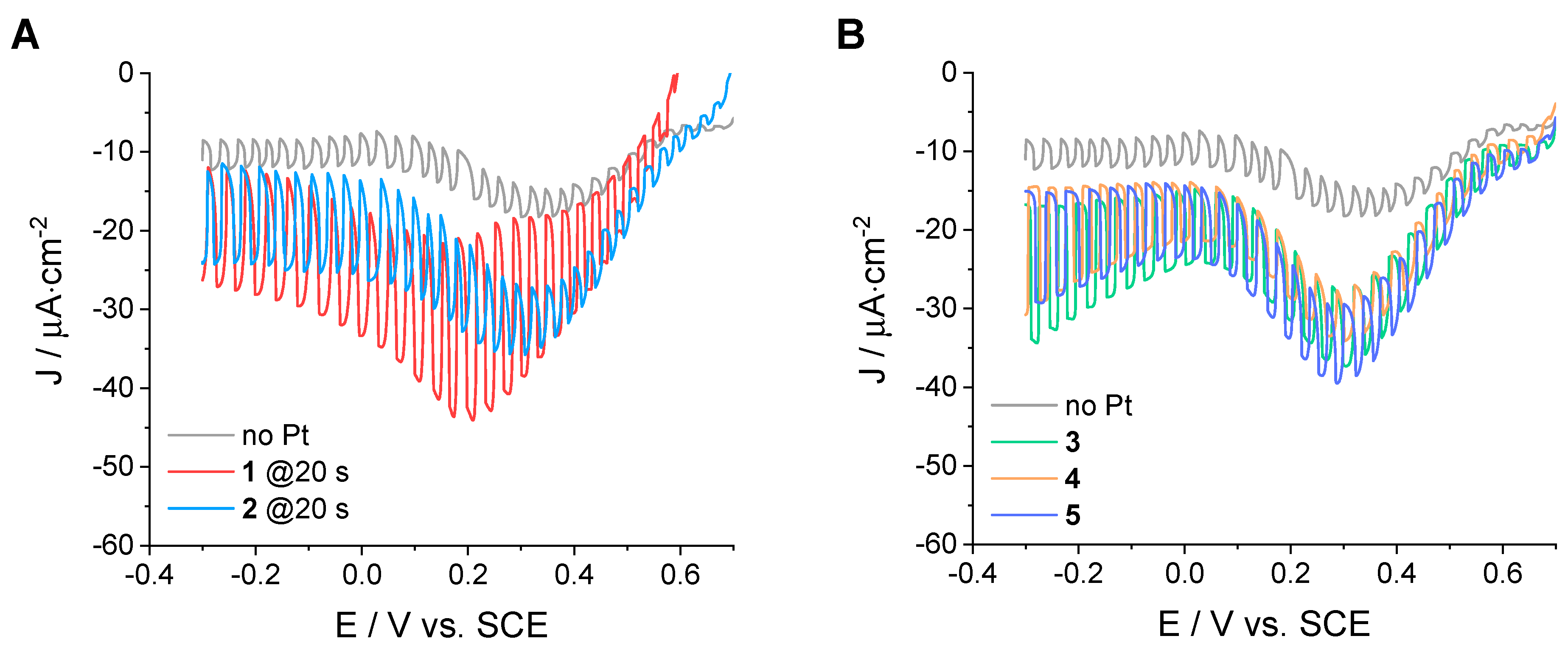
Figure 5 shows the relevant LSV curves obtained with such electrodes under chopped irradiation in 0.1 M acetate buffer at pH 4 (the corresponding CA experiments at an applied bias of −0.2 V vs. SCE are reported in the Supplementary Materials, Figures S21–S23). Similar to type A NiO electrodes, different deposition times were considered for Methods 1 and 2 (Figures S24 and S25), and the best performances were obtained at deposition times of 20 s (Figure 5A). The main evidence from the comparison of these data can be summarized as follows: (i) akin to NiO electrodes of type A, the attachment of Pt onto the sensitized NiO surface provides catalytic sites for proton reduction to dihydrogen, leading to enhanced photocurrent densities relative to those observed with the blank sample without metal on top; (ii) the measured photocurrent densities are overall lower than those observed with NiO electrodes of type A, which can be attributed to the reduced dye loading and corresponding light-harvesting ability as well as to the different morphology of the NiO film (mainly size and connectivity of the NiO nanoparticles), which might influence the efficiency of charge recombination phenomena [31]; (iii) within this limitation, potentiostatic methods (Methods 1 and 2) perform slightly better than the CV-based ones (Methods 3–5); (iv) the potentiostatic Method 1, which combines both potential bias and light, provides more active photocathodes (maximum photocurrent densities of −22 µA·cm−2 for the NiO-B|P1|Pt-1 sample at 20 s deposition time) than the analogue Method 2 without applied illumination (maximum photocurrent densities of −13 µA·cm−2 for the NiO-B|P1|Pt-2 sample at 20 s deposition time; see Figure 5A); (v) as to the potentiodynamic procedures (Methods 3–5), improved performances are attained with the NiO-B|P1|Pt-3 electrode (maximum photocurrent densities of −18 µA·cm−2) with respect to both NiO-B|P1|Pt-4 and NiO-B|P1|Pt-5 (maximum photocurrent densities of −14 and −15 µA·cm−2, respectively); (vi) similar to what was observed for NiO electrodes of type A, the importance of merging both potential and light is clearly evident for both potentiostatic and potentiodynamic methods, suggesting that the investigated deposition protocols could be well suited for future studies aimed at photoelectrochemical hydrogen generation using different sensitized NiO substrates.

4. Conclusions

A systematic investigation of Pt deposition onto NiO electrodes sensitized with the standard P1 dye has been accomplished using simple methodologies based on potentiostatic or potentiodynamic procedures either by employing or not employing an additional light bias. Photoelectrochemical characterization of the resulting electrodes showed that all platinization procedures lead to active photocathodes displaying enhanced photocurrent densities compared to the blank sample without Pt HEC. The best performances were achieved using fast deposition methods that couple both potential bias and light irradiation and were associated with a homogeneous distribution of small Pt islands on the sensitized NiO substrate. In these cases, the active participation of the P1 dye in the deposition process possibly leads to favorable chromophore–catalyst interactions that light-driven HER catalysis may benefit from. The similar results obtained using two different NiO substrates finally suggest that the simple photoelectrodeposition methods described here can be employed as general procedures for the preparation of NiO electrodes sensitized with novel dyes—either molecular- or material-based ones—towards the realization of active photocathodes for light-driven hydrogen production.

Supplementary Materials

The following supporting information can be downloaded at: https://www.mdpi.com/article/10.3390/app12104955/s1. Figure S1. LSV of sensitized NiO electrode of type A in N2-purged 0.1 M acetate buffer at pH 4 in the presence of 0.01 M [Co(NH3)5Cl]Cl2 as an irreversible electron acceptor. Figure S2. LSV of sensitized NiO electrode of type B in N2-purged 0.1 M acetate buffer at pH 4 in the presence of 0.01 M [Co(NH3)5Cl]Cl2 as an irreversible electron acceptor. Figure S3. Film thickness of NiO electrodes of type A and type B measured using profilometry. Figure S4. Section analyses of NiO electrodes of type A and type B measured using AFM. Figure S5. Absorption spectrum of a solution (optical pathlength of 1 cm) obtained after desorption of a sensitized NiO electrode of type A (average of three samples, surface area of 1.5 cm2) with 20 μL TBAOH 1 M in methanol and further dilution with methanol to a total volume of 3 mL. Figure S6. Absorption spectrum (average of three samples) of a NiO electrode of type B sensitized after overnight soaking in a 0.5 mM acetonitrile solution of the P1 dye. Figure S7. Absorption spectrum of a solution (optical pathlength of 1 cm) obtained after desorption of a sensitized NiO electrode of type B (average of three samples, surface area of 1.5 cm2) with 20 μL TBAOH 1 M in methanol and further dilution with methanol to a total volume of 3 mL. Figure S8. Exemplars of current vs. time trace recorded during the deposition with Method 1 of sensitized NiO electrodes of type A. Figure S9. Exemplar of current vs. voltage traces recorded during the deposition with Method 3 of sensitized NiO electrodes of type A. Figure S10. Exemplar of current vs. voltage traces recorded during the deposition with Method 4 of sensitized NiO electrodes of type A. Figure S11. Exemplar of current vs. voltage traces recorded during the deposition with Method 5 of sensitized NiO electrodes of type A. Figure S12. SEM/EDS analysis of NiO electrodes of type A prepared using Method 2 at 20 s. Figure S13. Representative LSV and CA of NiO-A|P1|Pt-1 at 20 s in N2-purged 0.1 M acetate buffer at pH 4 under chopped irradiation to highlight on-off light cycles and the procedure to estimate the maximum photocurrent density (ΔJmax). Figure S14. LSV of NiO-A|P1|Pt-1 at different deposition times in N2-purged 0.1 M acetate buffer at pH 4 under chopped irradiation. Figure S15. CA at −0.2 V vs. SCE of NiO-A|P1|Pt-1 at different deposition times in N2-purged 0.1 M acetate buffer at pH 4 under chopped irradiation. Figure S16. CA at −0.2 V vs. SCE of NiO-A|P1|Pt-2 at different deposition times in N2-purged 0.1 M acetate buffer at pH 4 under chopped irradiation. Figure S17. CA at −0.2 V vs. SCE of NiO-A|P1|Pt-n with n = 3–5 in N2-purged 0.1 M acetate buffer at pH 4 under chopped irradiation. Figure S18. Faradaic efficiency determination for NiO-A|P1|Pt-1 at 20 s in N2-purged 0.1 M acetate buffer at pH 4 under chopped irradiation: the NiO-based photocathode generator was held at −0.2 V vs. SCE while the Pt-based collector was held at +0.2 V vs. SCE. Figure S19. Faradaic efficiency determination for NiO-A|P1|Pt-5 in N2-purged 0.1 M acetate buffer at pH 4 under chopped irradiation: the NiO-based photocathode generator was held at −0.2 V vs. SCE while the Pt-based collector was held at +0.2 V vs. SCE. Figure S20. Faradaic efficiency determination for the non-platinized NiO electrode of type A in N2-purged 0.1 M acetate buffer at pH 4 under chopped irradiation: the NiO-based photocathode generator was held at −0.2 V vs. SCE while the Pt-based collector was held at +0.2 V vs. SCE. Figure S21. CA at −0.2 V vs. SCE of NiO-B|P1|Pt-1 at different deposition times in N2-purged 0.1 M acetate buffer at pH 4 under chopped irradiation. Figure S22. CA at −0.2 V vs. SCE of NiO-B|P1|Pt-2 at different deposition times in N2-purged 0.1 M acetate buffer at pH 4 under chopped irradiation. Figure S23. CA at −0.2 V vs. SCE of NiO-B|P1|Pt-n with n = 3–5 in N2-purged 0.1 M acetate buffer at pH 4 under chopped irradiation. Figure S24. LSV of NiO-B|P1|Pt-1 at different deposition times in N2-purged 0.1 M acetate buffer at pH 4 under chopped irradiation. Figure S25. LSV of NiO-B|P1|Pt-2 at different deposition times in N2-purged 0.1 M acetate buffer at pH 4 under chopped irradiation.

Author Contributions

Conceptualization, M.N.; investigation, F.D., E.B. and R.B.; data curation, F.D. and M.N.; writing—original draft preparation, M.N.; writing—review and editing, F.D., E.B., R.B. and M.N.; supervision, E.B. and M.N.; funding acquisition, M.N. All authors have read and agreed to the published version of the manuscript.

Funding

FAR2021: FIR2021 (University of Ferrara). PRIN 2020927WY3 “ElectroLight4Value” (Italian MUR).

Institutional Review Board Statement

Not applicable.

Informed Consent Statement

Not applicable.

Data Availability Statement

Not applicable.

Acknowledgments

Edoardo Marchini and Michele Mazzanti are gratefully acknowledged for help with measuring the film thickness. Marco Carmosino is acknowledged for assistance.

Conflicts of Interest

The authors declare no conflict of interest.

References

  1. Armaroli, N.; Balzani, V. The Hydrogen Issue. ChemSusChem 2011, 4, 21–36. [Google Scholar] [CrossRef] [PubMed]
  2. Nocera, D. Solar Fuels and Solar Chemicals Industry. Acc. Chem. Res. 2017, 50, 616–619. [Google Scholar] [CrossRef] [PubMed]
  3. Agosti, A.; Natali, M.; Amirav, L.; Bergamini, G. Towards Solar Factories: Prospects of Solar-to-Chemical Energy Conversion using Colloidal Semiconductor Photosynthetic Systems. ChemSusChem 2020, 13, 4894–4899. [Google Scholar] [CrossRef] [PubMed]
  4. Lin, L.; Hisatomi, T.; Chen, S.; Takata, T.; Domen, K. Visible-Light-Driven Photocatalytic Water Splitting: Recent Progress and Challenges. Trends Chem. 2020, 2, 813–824. [Google Scholar] [CrossRef]
  5. Yu, Z.; Li, F.; Sun, L. Recent Advances in Dye-Sensitized Photoelectrochemical Cells for Solar Hydrogen Production Based on Molecular Components. Energy Environ. Sci. 2015, 8, 760–776. [Google Scholar] [CrossRef]
  6. Xu, N.; McCool, N.S.; Mallouk, T.E. Water Splitting Dye-Sensitized Solar Cells. Nano Today 2017, 14, 42–58. [Google Scholar] [CrossRef]
  7. Hagfeldt, A.; Boschloo, G.; Sun, L.; Kloo, L.; Pettersson, H. Dye-Sensitized Solar Cells. Chem. Rev. 2010, 110, 6595–6663. [Google Scholar] [CrossRef]
  8. Odobel, F.; Le Pleux, L.; Pellegrin, Y.; Blart, E. New Photovoltaic Devices Based on the Sensitization of p-type Semiconductors: Challenges and Opportunities. Acc. Chem. Res. 2010, 43, 1063–1071. [Google Scholar] [CrossRef]
  9. Nikolaou, V.; Charisiadis, A.; Charalambidis, G.; Coutsolelos, A.G.; Odobel, F. Recent Advances and Insights in Dye-Sensitized NiO Photocathodes for Photovoltaic Devices. J. Mater. Chem. A 2017, 5, 21077–21113. [Google Scholar] [CrossRef]
  10. Gibson, E.A. Dye-Sensitized Photocathodes for H2 Evolution. Chem. Soc. Rev. 2017, 46, 6194–6209. [Google Scholar] [CrossRef]
  11. Antila, L.J.; Ghamgosar, P.; Maji, S.; Tian, H.; Ott, S.; Hammarström, L. Dynamics and Photochemical H2 Evolution of Dye-NiO Photocathodes with a Biomimetic FeFe-Catalyst. ACS Energy Lett. 2016, 1, 1106–1111. [Google Scholar] [CrossRef] [Green Version]
  12. Kaeffer, N.; Massin, J.; Lebrun, C.; Renault, O.; Chavarot-Kerlidou, M.; Artero, V. Covalent Design for Dye-Sensitized H2-Evolving Photocathodes Based on a Cobalt Diimine−Dioxime Catalyst. J. Am. Chem. Soc. 2016, 138, 12308–12311. [Google Scholar] [CrossRef] [PubMed] [Green Version]
  13. Gross, M.A.; Creissen, C.E.; Orchard, K.L.; Reisner, E. Photoelectrochemical Hydrogen Production in Water Using a Layer-by-Layer Assembly of a Ru Dye and Ni Catalyst on NiO. Chem. Sci. 2016, 7, 5537–5546. [Google Scholar] [CrossRef] [PubMed] [Green Version]
  14. Hoogeveen, D.A.; Fournier, M.; Bonke, S.A.; Fang, X.Y.; Mozer, A.J.; Mishra, A.; Bäuerle, P.; Simonov, A.N.; Spiccia, L. Photo-electrocatalytic Hydrogen Generation at Dye-Sensitised Electrodes Functionalised with a Heterogeneous Metal Catalyst. Electrochim. Acta 2016, 219, 773–780. [Google Scholar] [CrossRef]
  15. Szaniawska, E.; Wadas, A.; Ramanitra, H.H.; Fodeke, E.A.; Brzozowska, K.; Chevillot-Biraud, A.; Santoni, M.-P.; Rutkowska, I.A.; Jouini, M.; Kulesza, P.J. Visible-Light-Driven CO2 Reduction on Dye-Sensitized NiO Photocathodes Decorated with Palladium Nanoparticles. RSC Adv. 2020, 10, 31680–31690. [Google Scholar] [CrossRef]
  16. Benazzi, E.; Cristino, V.; Boaretto, R.; Caramori, S.; Natali, M. Photoelectrochemical Hydrogen Evolution Using CdTexS1-x Quantum Dots as Sensitizers on NiO Photocathodes. Dalton Trans. 2021, 50, 696–704. [Google Scholar] [CrossRef]
  17. Qin, P.; Zhu, H.; Edvinsson, T.; Boschloo, G.; Hagfeldt, A.; Sun, L. Design of an Organic Chromophore for p-Type Dye-Sensitized Solar Cells. J. Am. Chem. Soc. 2008, 130, 8570–8571. [Google Scholar] [CrossRef]
  18. Li, L.; Duan, L.; Wen, F.; Li, C.; Wang, M.; Hagfeldt, A.; Sun, L. Visible Light Driven Hydrogen Production from a Photo-active Cathode Based on a Molecular Catalyst and Organic Dye-Sensitized p-type Nanostructured NiO. Chem. Commun. 2012, 48, 988–990. [Google Scholar] [CrossRef]
  19. Wood, C.J.; Summers, G.H.; Clark, C.A.; Kaeffer, N.; Braeutigam, M.; Carbone, L.R.; D’Amario, L.; Fan, K.; Farré, Y.; Narbey, S.; et al. A Comprehensive Comparison of Dye-Sensitized NiO Photocathodes for Solar Energy Applications. Phys. Chem. Chem. Phys. 2016, 18, 10727–10738. [Google Scholar] [CrossRef] [Green Version]
  20. Sherman, B.D.; Sheridan, M.V.; Dares, C.J.; Meyer, T.J. Two Electrode Collector–Generator Method for the Detection of Electrochemically or Photoelectrochemically Produced O2. Anal. Chem. 2016, 88, 7076–7082. [Google Scholar] [CrossRef]
  21. Sumikura, S.; Mori, S.; Shimizu, S.; Usami, H.; Suzuki, E. Syntheses of NiO Nanoporous Films Using Nonionic Triblock Co-Polymer Templates and Their Application to Photo-Cathodes of p-Type Dye-Sensitized Solar Cells. J. Photochem. Photobiol. A 2008, 199, 1–7. [Google Scholar] [CrossRef]
  22. Kreutler, B.; Bard, A.J. Heterogeneous Photocatalytic Preparation of Supported Catalysts. Photodeposition of Platinum on TiO2 Powder and Other Substrates. J. Am. Chem. Soc. 1978, 100, 4317–4318. [Google Scholar] [CrossRef]
  23. Massin, J.; Lyu, S.; Pavone, M.; Muñoz-Garcia, A.B.; Kauffmann, B.; Toupance, T.; Chavarot-Kerlidou, M.; Artero, V.; Olivier, C. Design and Synthesis of Novel Organometallic Dyes for NiO Sensitization and Photo-Electrochemical Applications. Dalton Trans. 2016, 45, 12539–12547. [Google Scholar] [CrossRef]
  24. Bard, A.J.; Faulkner, L.R. Electrochemical Methods: Fundamentals and Applications; Wiley: Hoboken, NJ, USA, 2001. [Google Scholar]
  25. Kawamura, Y.L.; Sakka, T.; Ogata, Y.H. Photoassisted Control of Pt Electrodeposition on p-Type Si. J. Electrochem. Soc. 2005, 152, C701–C705. [Google Scholar] [CrossRef]
  26. Stoychev, D.; Papoutis, A.; Kelaidopoulou, A.; Kokkinidis, G.; Milchev, A. Electrodeposition of Platinum on Metallic and Nonmetallic Substrates—Selection of Experimental Conditions. Mater. Chem. Phys. 2001, 72, 360–365. [Google Scholar] [CrossRef]
  27. Zhang, H.; Zhou, W.; Du, Y.; Yang, P.; Wang, C. One-Step Electrodeposition of Platinum Nanoflowers and Their High Efficient Catalytic Activity for Methanol Electro-Oxidation. Electrochem. Commun. 2010, 12, 882–885. [Google Scholar] [CrossRef]
  28. Chu, X.; Duan, D.; Shen, G.; Yu, R. Amperometric Glucose Biosensor Based on Electrodeposition of Platinum Nanoparticles onto Covalently Immobilized Carbon Nanotube Electrode. Talanta 2007, 71, 2040–2047. [Google Scholar] [CrossRef]
  29. Rossi, R.C.; Tan, M.X.; Lewis, N.S. Size-Dependent Electrical Behavior of Spatially Inhomogeneous Barrier Height Regions on Silicon. Appl. Phys. Lett. 2000, 77, 2698–2700. [Google Scholar] [CrossRef]
  30. Maffeis, V.; Jousselme, B.; Gustavsson, T. Hole Injection from P1 dye Hot-Excited States in p-Type Dye-Sensitized Films: A Fluorescence Study. Photochem. Photobio. Sci. 2021, 20, 1257–1271. [Google Scholar] [CrossRef] [PubMed]
  31. Tian, L.; Tyburski, R.; Wen, C.; Sun, R.; Abdellah, M.; Huang, J.; D’Amario, L.; Boschloo, G.; Hammarström, L.; Tian, H. Understanding the Role of Surface States on Mesoporous NiO Films. J. Am. Chem. Soc. 2020, 142, 18668–18678. [Google Scholar] [CrossRef] [PubMed]
Figure 1. (A) Pictorial representation of the NiO photocathode and the related mechanistic pathways towards hydrogen evolution; (B) molecular structure of the P1 dye; pictures of a sensitized NiO electrode of (C) type A and (D) type B.
Applsci 12 04955 g001
Figure 2. SEM micrographs (A,B) and AFM images (C,D) of NiO electrodes of type A (A,C) and type B (B,D).
Applsci 12 04955 g002
Figure 3. SEM micrographs (A,D), corresponding EDS elemental maps (B,E), and AFM images (C,F) of sensitized NiO electrodes of type A after Pt deposition using Method 1 at 20 s deposition time (AC) and Method 5 (DF).
Applsci 12 04955 g003
Figure 4. LSV of sensitized electrodes: (A) NiO-A|P1|Pt-1, (B) NiO-A|P1|Pt-2, and (C) NiO-A|P1|Pt-3–5 in N2-purged 0.1 M acetate buffer at pH 4 under chopped irradiation (in every graph, a comparison is made with the blank non-platinized electrode, grey trace); (D) photoaction spectra of NiO-A|P1|Pt-1 at 20 s deposition time, NiO-A|P1|Pt-5, and the blank non-platinized electrode.
Applsci 12 04955 g004
Figure 5. LSV of sensitized electrodes (A) NiO-B|P1|Pt-1 and NiO-B|P1|Pt-2 at 20 s deposition time and (B) NiO-B|P1|Pt-35 in N2-purged 0.1 M acetate buffer at pH 4 under chopped irradiation (in every graph, a comparison is made with the blank non-platinized electrode, grey trace).
Applsci 12 04955 g005
Publisher’s Note: MDPI stays neutral with regard to jurisdictional claims in published maps and institutional affiliations.

