Abstract
When a high-speed train is running in a tunnel, the global navigation satellite system (GNSS) signal is completely lost. Relying only on the inertial navigation system (INS) composed of Micro-electromechanical Systems (MEMS) devices leads to large navigation errors. To solve this problem, an integrated micro inertial measurement unit (MIMU), odometer (ODO), and motion constraint (MC) tunnel navigation method is proposed. This method first establishes a motion constraint model based on the installation angles of MIMU; secondly, the effect of turning on the motion constraint model and the odometer is analyzed and the use condition of the motion constraints is obtained; the installation angles of MIMU are then estimated when GNSS signal is good and the use condition of the motion constraints is met; finally, the forward speed measured by the odometer and the motion constraints are applied to suppress the error of the INS and improve the navigation accuracy in the tunnel. Based on this method, high-speed train navigation tests were carried out both in areal tunnel environment and in a case study with an artificially disconnected GNSS signal. The experimental results showed that the navigation accuracy of the train in the tunnel was significantly improved. Seamless navigation was achieved inside and outside the tunnel, which verified the effectiveness of the method.
1. Introduction
As the high-speed railway network becomes denser and the number of trains running on the network increases, the safety of high-speed trains has become an issue of great concern [1,2]. There is a requirement for real-time, continuous, accurate, and reliable navigation information for the operation control system to control, schedule, and monitor train movements [1,3,4]. In tunnels, the GNSS signal is lost and there is a lack of other available information, which presents a challenge to these navigation systems [4]. The issue has drawn particular attention from academics, with both China and the European community funding related research projects [5].
Traditional train positioning uses speed and distance measurement methods such as track circuits, transponders, axle-counting equipment, and Doppler radar to unify the speed and location of the moving train under one-dimensional coordinates [4].Currently, the positioning accuracy of distances required by the European Train Control System (ETCS) and the Chinese Train Control System (CTCS), based on balise groups placed on the track and odometer readings, is measured distance [5]. However, there has been a gradual trend towards the reduction of expensive and complex trackside equipment in train positioning technology development [5]. Traditional methods are associated with poor positioning accuracy, less train information, complicated system maintenance, and inability to meet the requirements of high-speed train positioning in long tunnels [6]. Today, the most commonly used train navigation sensors are GNSS, INS, camera, Doppler speedometer, barometric altimeter, odometer, lidar, electronic maps, and specially designed equipment [6]. However, none of these sensors can independently meet the requirements of navigation accuracy in all environments, and multisensor combined navigation that can integrate their respective advantages has become the development trend of train navigation [7,8]. Due to complementary nature of GNSS and INS, they form the basis of integrated train navigation systems. However, in long tunnels where there is no GNSS signal, it is difficult to ensure navigation accuracy by relying only on the INS composed of MEMS devices [5,9,10].
In recent years, many scholars have conducted research on train navigation in tunnels. Some scholars have proposed methods for establishing reference information in tunnels. Li proposed a received signal strength indication (RSSI) positioning method based on ZigBee technology [11], but the error increased significantly as the speed increased. Zheng conducted an INS and radio frequency identification (RFID) integrated navigation simulation experiment and achieved an astonishing 1.5 m accuracy over a 500 s GNSS outage [12]. However, it is difficult to provide precise locations for RFID tags in long tunnels, and the high speed of trains is also a challenge to RFID [13]. Liu proposed a method of combining INS and map matching (MM) [4], but did not report the positioning accuracy during GNSS outage. It is also uncertain whether MM can suppress the error of INS. Establishing a high-precision digital map is difficult in a long tunnel. Some studies using multisensor information fusion methods have achieved meter-level accuracy in tunnels [4,5,10,14]. However, these systems are very complicated and costly, and there are cumbersome installation and calibration processes for sensors. Some scholars have proposed methods based on track and train motion constraint information. Wang proposed a method based on a train motion model and track constraints [15], which had poor accuracy. Liang used a combination of a train motion model and a gyroscope to locate trains in tunnels [16], which produced a horizontal position error of 31 mover 10 s and a large position error. Yang used train motion constraints to suppress the INS error [17], which significantly improved the accuracy of train navigation. However, the MIMU installation angles were not considered in the motion constraint model and the accuracy needed to be improved. Reimer used a high-precision INS/odometer combination method to solve the problem of train positioning in tunnels, and achieved amazing positioning accuracy by modeling and analyzing the influence of turning on the odometer measurement [9]. However, the system was expensive and Reimer did not attempt to achieve the accuracy that low-precision MEMS inertial devices can attain.
In the field of track inspection, where millimeter-level accuracy is required, Chen designed a track trolley based on high-precision laser INS/GNSS integrated navigation [18], and used motion constraints to improve the accuracy of the system during GNSS signal outage. Since the installation angles were not considered, the improvement of system accuracy was limited. Zhang considered the installation angles in a motion constraint model for the above system [19], but did not mention how to obtain them. Zhu used the method of similar rotation to obtain these installation angles through data post-processing [20], but the installation angles were not used for motion constraints. Obtaining accurate MIMU installation angles is key to improving the effect of motion constraints [10,21].
In this paper, our first aim was to improve the traditional motion constraint method on the basis of train motion analysis without adding additional sensors, which constrain the lateral and up speeds of the train, and thus to improve the motion constraint suppression effect on the error associated with a pure inertial navigation system (P-INS). Our second aim was to use the speed measured by the odometer installed on the train wheel to constrain the forward speed of the train on the basis of the motion constraint, so as to provide the constraint on the three-dimensional speed of the train. However, accurate estimation of the installation angles of the MIMU and the influence of the train’s maneuvering turn on the three-dimensional motion constraints were key challenges. Our main contributions are summarized as follows:
- (1)
- A method for high-speed train positioning in tunnels based on integrated MIMU/odometer/MC navigation is proposed;
- (2)
- A motion constraint model is established with the installation angles of MIMU, and the influence of turning on motion constraint is analyzed;
- (3)
- The installation angles of MIMU are estimated online when the GNSS signal is good and the use condition of motion constraints is met;
- (4)
- The estimated installation angles and the forward speed measured by the odometer are applied to suppress the INS error in tunnel navigation. Based on this method, high-speed train navigation tests were carried out in both a real tunnel environment and a case study using an artificially disconnected GNSS signal.
The remainder of this paper is organized as follows: Section 2 introduces the motion constraints and the odometer, Section 3 describes the filter model and algorithm flow, Section 4 describes the experimental system and equipment, Section 5 discusses the results of the test, and the conclusions are given in Section 6.
2. Train Motion Constraints and Odometer
2.1. Motion Constraints Model
Defining the train body frame as m, the origin is the installation position of the MIMU on the carriage of the train. The x, y, and z axes point to the right, forward, and upward relative to the train body, respectively. Defining the MIMU frame as b, the directions of each axis of the b frame should be consistent with the direction of each axis of the m frame to ensure that the installation angles are as small as possible.
A high-speed train’s wheels are pressed against the rails during running [22], and, assuming there is no side slip or jumping, the speeds of the x and z axes in the m frame are approximately zero. Ignoring the influence of the installation lever arm between the MIMU and the GNSS receiver, the constraint relationship is expressed as
where is the INS output speed in the n frame(local geographic coordinate frame), represents the rotation matrix from the n frame to the b frame; and are the speed of the train in the m frame; and is the conversion cosine matrix between the b frame and the m frame, which can be calculated from the installation angles .
Once the MIMU is fixed on the train, the errors of installation angles can be regarded as random constants with small angles. According to the conclusion reported in Reference [22], the roll installation angle has no effect on the motion constraints. Regardless of the influence of the roll installation angle error, the three-dimensional vector form of the remaining two installation angle errors is .
The estimated conversion matrix can be expressed as
The conversion matrix error can be expressed as
2.2. Train Turning Influence on Motion Constraints
The curved line of a high-speed railway track is generally composed of a straight line, a gentle curve, and a circular curve [22], as shown in Figure 1. There is an installation lever arm between the rotational center of the train body and the MIMU, and the lever arm speed exists at the position of the MIMU during turning [2,23].
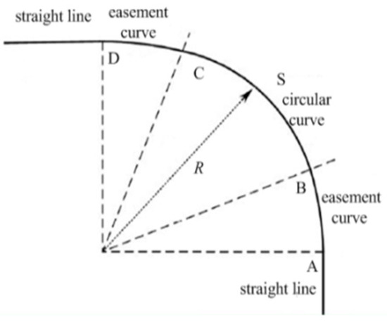
Figure 1.
Track curve line plan. A, B, C and D are the four points on the train track. Segment S is a circular curve with a turning radius of R.
The train turns under the cooperation of the forward traction, track, bogie, and wheels [24]. The structure of the bogie is shown in Figure 2. Each bogie contains four wheels, and each carriage has two bogies. The carriage is mounted on the bogie through two bogie pins, several springs, and dampers. This structure allows for a certain degree of rotation between the carriage box and the wheels.
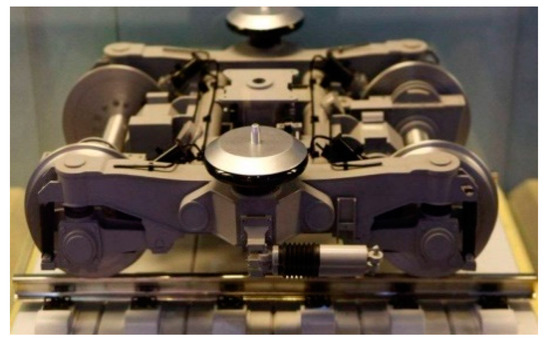
Figure 2.
Physical map of bogie.
In order to simplify the analysis, select the S section shown in Figure 1, and assume that the train is turning left. The turning motion of the train is shown in Figure 3.
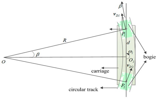
Figure 3.
Geometric analysis of train turning.
The bogies of the train sit on a curved track with a radius . and are the pins of the front and rear bogies; the carriage box lies on the secant between the two pins. The bogies are approximately tangential to the curve, and the carriage lies on the secant between the two pins [24]. There is an misalignment angle between the axis of the bogie and the carriage [10]. The misalignment angle is given by
where is distance between and . The carriage rotates around during turning, and the angular rate of rotation is
where is the velocity of the front bogie’s pin. Assuming MIMU is installed at point , we have
where is the velocity of the MIMU in the n frame.
The assumption is now violated in the m frame because of the carriage’s rotation around .We can find the velocity of the carriage in the m frame as follows:
Assume a velocity of 350 km/h, a distance of 20 m between the bogie pins and a curve radius of 5000 m [22]. The lateral velocity of carriage due to the turning will be
This would pose a large risk of corruption of the extended Kalman filter (EKF) state estimates. Substituting Equation (5) into Equation (7) gives
Where is the output of the z-axis gyro.
Of course, turning maneuvers are quite complicated. Both the front and rear bogies have varying angular rates of rotation and the center of rotation is not fixed, which makes it difficult to accurately model the lateral velocity. However, this still provides a theoretical basis for judging whether the hypothesis that the lateral velocity is zero holds.
2.3. TheThreshold for Motion Constraints
In order to reduce the effect of turning on motion constraints, the turning angle rate output by the z-axis gyro is used to judge whether the motion constraints can be used, expressed as follows:
where is the bias of the z-axis gyro and is the judgment threshold. The train z-axis gyro data collected in the experiment are shown in Figure 4.
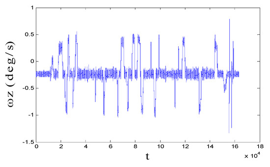
Figure 4.
The measurement of data from the z-axis gyroscope.
Find the threshold as follows:
where is the adjustment factor and can be selected according to the movement status, is the average value of the non-turning data, and and are the upper and lower edge values of the data band in the non-turning stage, respectively.
2.4. Odometer
The axle pulse odometer is installed at the wheel of the train, as shown in Figure 5. The odometer can measure the train’s speed by recording the cumulative number of revolutions of the wheel and calculating speed using the wheel diameter.
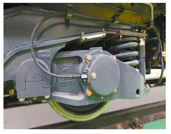
Figure 5.
Physical map of train odometer.
The speed obtained by the odometer is calculated as
where is the total number of pulses output by the odometer at time , is the number of pulses given the wheel rotates a full turn, is the interval between time and time , and is the wheel diameter.
Defining the train bogie frame as o, the origin of the o frame is the pin of the bogie. The x, y, and z axes point to the right, forward, and upwards relative to the bogie, respectively. The speed output of the odometer in the bogie frame (o frame) is
When the train is traveling in a straight line, the bogie coordinate frame and the train body frame are approximately coincident; that is .
where is the transformation matrix from the o frame to the m frame.
3. Model and Algorithm Flow
In this section, corresponding filter models are described, which were designed based on the judgment of GNSS signals and the train movement status.
3.1. Algorithm Flow
According to the train movement status and the observation environment of the GNSS signal, three filter models were established. The algorithm flow is shown in Figure 6.
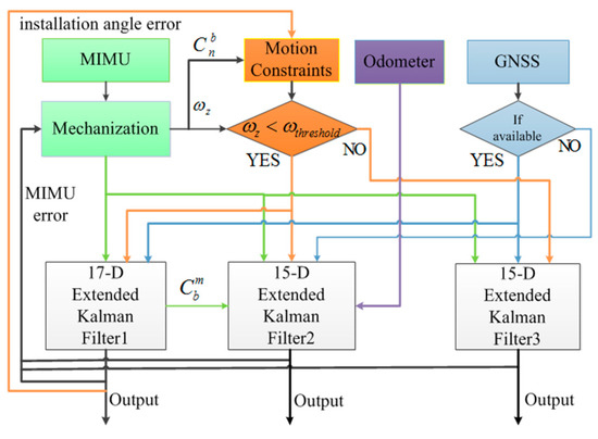
Figure 6.
Navigation Algorithm Flowchart.
When GNSS signal and the motion constraints are all available, they are used to provide measurements for the 17-dimensional EKF1 to estimate state quantities. The installation angles can be found through feedback correction. When there is a GNSS signal outage in a tunnel and the motion constraints are available, the observations of the 15-dimensional EKF2 are provided by the odometer and motion constraints with the installation angles estimated by EKF1. When the GNSS signal is available but the motion constraints are unavailable, observations of the 15-dimensional EKF3 are provided by GNSS. The errors of the inertial devices estimated by the filter are fed back to the inertial navigation algorithm.
If the navigation mode changes, the public states and their error covariance matrix are transferred from the old algorithm to the new algorithm, and other quantities are not updated [25]. If the state vector is switched from to at time k, in is directly removed and saved, the elements in the row and column corresponding to in are directly removed and saved, and the remaining quantities remain unchanged. If the state vector at time k switches from to , the previously saved estimate of is expended on . In the absence of GNSS, the accuracy of state estimation will be reduced; the original saved covariance matrix elements corresponding to are then enlarged, is expanded, and the remaining elements of are multiplied by an appropriate factor. The above configuration of and is necessary to maintain the consistency of EKF.
3.2. MIMU/GNSS Loose Integration Model
When the train is turning and the GNSS signal is good, the motion constraints are unavailable. In this case, the 15-dimensional MIMU/GNSS loose combination EKF filter is used for train navigation. The state error vector of the system is defined as
where denotes the attitude errors, denotes the velocity errors, denotes the positioning errors, denotes the bias errors of the gyroscopes in the b frame, and denotes the bias errors of accelerometers in the b frame.
The state equation can be written as
where is the state transfer matrix, is the noise transferring matrix, and is the state model noise matrix. and are defined as
where represents the rotation matrix from the b frame to the n frame, represents the i-axis gyroscope noise where , and represents the i-axis accelerometer noise.
The measurement model of GNSS/MIMU integration can be expressed as
where denotes the measurement matrix, and are the speed and position of the inertial navigation system in the n frame, and are the speed and position of the receiver in the n frame, denotes the observation matrix, and denotes the GNSS measurement noise.
The detailed description of is
3.3. MIMU/GNSS/MC Integration Model
When motion constraints are available and the GNSS signal is good, the installation angles can be estimated. The pitch installation angle error and the heading installation angle error are expanded into the error state. The new error state vector is
where ; and are modeled as Gaussian white noise:
The state equation after expansion is
where , .
Combining (3), the total differential of (1) is
where ; ; ; .
Combining (1), the measurement equation composed of motion constraints is expressed as
where denotes the measurement matrix, and are the speed of train in the m frame, is the noise matrix, and the measurement matrix is expressed as
where is all elements in the k-th row of matrix and .
Combining (19) and (25), the combined observation equation composed of GNSS and motion constraints is
The frequency of motion constraints is set to 1 Hz and synchronized with GNSS observation data. Through feedback correction, the installation angles can be calculated.
3.4. MIMU/MC/ODO Integration Model Odometer
Curved tracks are set in tunnels only in extreme cases. The length of such curves should be as short as possible and the radius should be as large as possible [22]. Even if there is a short turn, the navigation can be completed by P-INS.
When the GNSS signal is completely lost in a tunnel, the installation angle errors are no longer estimated since there is no position or other speed reference. Motion constraints provide virtual lateral and upward speed observations of the train body. The state equation is the same as Equation (16), and the state vector is 15-dimensional. Regarding the estimated MIMU installation angles as priori constant values, the third part of Equation (24) is zero. Equation (24) can be rewritten as
The forward speed error of the train can be obtained from the difference between the forward speed obtained by the MIMU and the odometer:
The observation equation composed of Equations (28) and (29) is
where the observation matrix is rewritten as
4. Experiment Description
The high-speed train navigation system described here is composed of MIMU (50 Hz), GNSS module (1 Hz), odometer (1 Hz), and a Cortex-A9 + FPGA hardware platform. The integrated navigation module was fixed on the train floor; the receiver antenna was fixed on the top of the train directly above the integrated navigation module; the PC received and stored experimental data through the serial port. The system composition is shown in Figure 7. The GNSS module adopted three-mode (GPS + Beidou + Galileo) and satellite-based enhancement. The specifications of the MIMU and odometer are listed in Table 1.
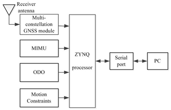
Figure 7.
Integrated navigation and data acquisition system.

Table 1.
Sensor specifications.
5. Experiment Results
5.1. MIMU Installation Angles Estimation Result
When GNSS signal and motion constraints were all available, the installation angles were estimated. In other cases, the installation angles were kept at the original value, as shown in Figure 8.
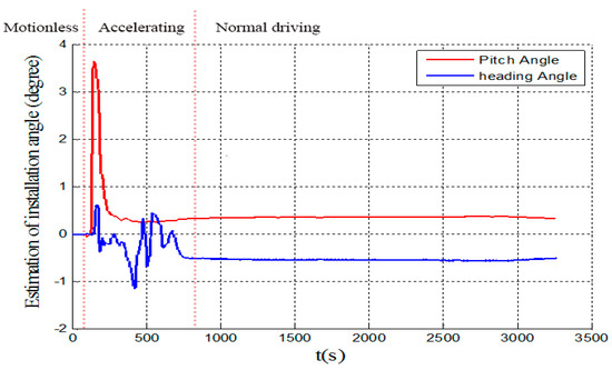
Figure 8.
MIMU installation angles.
During the start-up phase of the train’s movement, the acceleration is unstable and the speed is small. The observability of installation angles is closely related to train speed and acceleration [26,27], so the estimated installation angles fluctuated significantly at this time. As the speed increased, the estimates of the installation angles gradually converged.The installation angles were basically stable during the constant speed driving phase. Compared with the pitch installation angle, the heading installation angle had a slower convergence, which may have been related to the lack of heading maneuver of the train and the low accuracy of the initial heading angle. There was a certain coupling relationship between the attitude misalignment angles and the installation angles [27].
5.2. Tunnel Exit Positioning Result
The GNSS signal was completely lost in the tunnel. After exiting the tunnel, the receiver needed to capture and track the GNSS signal again. We set reference points near the tunnel exit using real-time kinematic (RTK) positioning technology. The GNSS module still could not achieve positioning at the reference points. Based on the sampled data in the real tunnel environment, the navigation results of four algorithms were compared: MIMU/ODO/MC integrated navigation; Considers the Installation Angles of MIMU for Motion Constraints aided Inertial Navigation System (CIAMC-INS); Traditional Motion Constraints without installation angles aided Inertial Navigation System (TMC-INS); Pure Inertial Navigation System (P-INS). The results were projected to the same layer of Google Earth, as shown in Figure 9. The trajectories are shown in blue, green, black, and red, respectively. Statistical results of the horizontal position errors at the reference points are shown in Table 2.
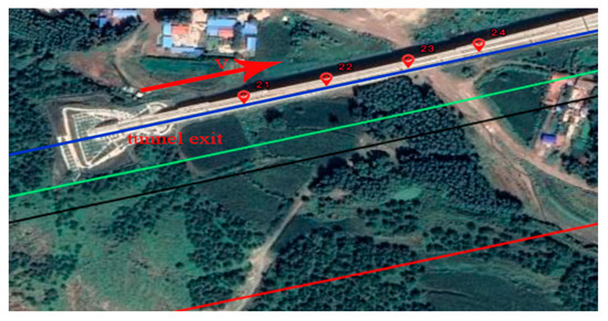
Figure 9.
Trajectory located at the exit of 9063 m tunnel.

Table 2.
Horizontal position errors of different algorithms at the reference points near the 9063 m tunnel exit.
The horizontal position error of MIMU/ODO/MC was 98.8%, 95.0%, and 91.6% lower than that of P-INS, TMC-INS, and CIAMC-INS, respectively. The horizontal errors and percentage errors of P-INS, TMC-INS, and CIAMC-INS algorithms all accumulated over time in the absence of a GNSS signal. The CIAMC-INS had a more obvious suppression effect on the position error of P-INS than TMC-INS, and the error increased more slowly. The MIMU/ODO/MC integrated navigation added a forward speed constraint of the train body on the basis of the CIAMC-INS algorithm and realized seamless positioning inside and outside the tunnel.
5.3. Navigation Results in Tunnel
In order to further analyze the effectiveness and navigation accuracy of the MIMU/ODO/MC algorithm inside the tunnel, a section of open area data was selected, and the smoothed result of the GNSS/MIMU integrated navigation was used as reference. GNSS data was disconnected for 100 s to simulate the GNSS signal outage in a tunnel. The differences between the results of the four algorithms and the reference were defined as corresponding errors. The train traveled 9515 m during the GNSS outage, as shown in Figure 10.
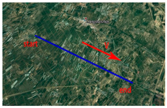
Figure 10.
Test trajectory with disconnected GNSS signal.
The position errors of the four algorithms are presented in Figure 11. The velocity errors of the four algorithms are presented in Figure 12.The attitude angle errors of the four algorithms are presented in Figure 13. The 100 s error and root mean square error (RMSE) of the navigation results of the four algorithms are shown in Table 3.

Figure 11.
Position error curves of four algorithms without GNSS signal. (a) East position error curves; (b) north position error curves; (c) height position error curves.

Figure 12.
Velocity error curves of four algorithms without GNSS signal. (a) East velocity error curves; (b) north velocity error curves; (c) upwards velocity error curves.

Figure 13.
Attitude error curves of four algorithms without GNSS signal. (a) Pitch angle error curves; (b) roll angle error curves; (c) heading angle error curves.

Table 3.
Navigation errors of different algorithms at the reference point near the 9063 m tunnel exit.
As shown in Figure 11 and Table 3, the position error of MIMU/ODO/MC was significantly less than those of P-INS, TMC-INS, and CIAMC-INS.
Both CIAMC-INS and TMC-INS were able to suppress the position errors of P-INS, but the effect on the upwards position error was better. This is related to the higher accuracy of pitch installation angle estimation. Due to the lack of constraints on the forward speed of the vehicle body, the position errors associated with the CIAMC-INS and TMC-INS algorithms still accumulated significantly. By adding the forward speed of the train body measured by the odometer as an observation, the MIMU/ODO/MC integrated navigation was able to obtain meter-level positioning accuracy and realize seamless positioning inside and outside the tunnel. The position error percentages of the four algorithms were 3.25%, 0.87%, 0.43%, and 0.05%.
As shown in Figure 12 and Table 3, the velocity error of MIMU/ODO/MC was significantly less than those of P-INS, TMC-INS, and CIAMC-INS
TMC-INS, CIAMC-INS, and MIMU/ODO/MC all suppressed the velocity errors of P-INS. However, MIMU/ODO/MC had the lowest 100 s velocity errors and RMSE. Compared with TMC-INS and CIAMC-INS, MIMU/ODO/MC was able tosuppressthe velocity errors of P-INS more effectively.
As shown in Figure 13 and Table 3, the 100 s attitude angle error of MIMU/ODO/MC was significantly less than those of P-INS, TMC-INS, and CIAMC-INS.
TMC-INS, CIAMC-INS, and MIMU/ODO/MC could all suppress the attitude angle errors of P-INS. MIMU/ODO/MC had the lowest 100 s attitude angle error and RMSE. Compared with TMC-INS and CIAMC-INS, MIMU/ODO/MC suppressed the attitude angle errors of P-INS more effectively.
6. Discussion
In this paper, experiments conducted under the conditions of a real tunnel and artificial disconnection of GNSS signal achieved the expected results. Due to the low accuracy of the MEMS inertial devices used, the positioning error of P-INS algorithm diverged quickly in a long tunnel without GNSS signal. TMC-INS reduced the positioning error to one quarter of the original. Based on the TMC-INS algorithm, the CIAMC-INS algorithm considering the MIMU installation angles improved the accuracy of TMC-INS by about 40%. It was shown that it is necessary to consider the installation angles of MIMU when using motion constraints, and that the method of estimating the installation angles online is feasible. However, the CIAMC-INS algorithm does not meet the requirements of meter-level positioning accuracy for long tunnels. The MIMU/ODO/MC method combined with the odometer used to measure the forward speed of the train satisfied the requirements of meter-level positioning accuracy in along tunnel, and the effect of three-dimensional speed constraints was obviously better than that of two-dimensional speed constraints.
7. Conclusions
In this paper, we propose a MIMU/ODO/MC integrated navigation method to solve the problem of the large positioning errors when depending solely on INS composed of MEMS in tunnels. Our approach makes full use of the train motion constraints and sensors that already exist on trains (odometer). In order to better exploit the potential of motion constraints, we consider the installation angles of MIMU relative to the train body in the motion constraint model. The installation angles are estimated online when both the GNSS and the motion constraints are available. In a tunnel, the train motion constraints provide the lateral and upward velocity observations, and the odometer provides the forward velocity observation. The tests carried out in a real tunnel environment and with an artificially disconnected GNSS signal both showed that the accuracy of the MIMU/ODO/MC integrated method was significantly higher than any of P-INS, TMC-INS, and CIAMC-INS, and achieved seamless navigation inside and outside the tunnel. However, there are still shortcomings in our method. For example, the navigation accuracy of the algorithm will decrease in long, curved tunnels. In future work, we will consider the lateral and upward velocity caused by the train turning in the motion constraint model in order to improve the adaptability of the algorithm to various patterns of train movement. In addition, we will study how to apply this method in other contexts to improve navigation accuracy when satellite signals are disturbed.
Author Contributions
Z.S. and K.T. discussed and designed the methodology. K.T. provided the dataset for experiment. Z.S. and X.W. completed the simulation program. M.W. and Y.G. verified the rationality of the experiment. Y.G. polished the manuscript. K.T. and M.W. revised the paper. All authors have read and agreed to the published version of the manuscript.
Funding
This research was funded by the National Natural Science Foundation of China under grants 61973312 and young teacher innovation research project of the College of Intelligent Science, National University of Defense Technology under grants ZN2019-16.
Institutional Review Board Statement
This paper does not involve human or animal research.
Informed Consent Statement
This paper does not involve human or animal research.
Data Availability Statement
The study did not report any data.
Acknowledgments
The author would like to thank all the teachers and colleagues who provided inspiration and equipment in the experiment. The author would like to thank all the anonymous reviewers for their meticulous comments and helpful suggestions.
Conflicts of Interest
The authors declare no conflict of interest.
References
- Muniandi, G.; Deenadayalan, E. Train distance and speed estimation using multi sensor data fusion. IET Radar. Sonar. Navig. 2019, 13, 664–671. [Google Scholar] [CrossRef]
- Hamid, H.; Nicholson, G.; Roberts, C. Impact of train positioning inaccuracies on railway traffic management systems: Framework development and impacts on TMS functions. IET Intell. Trans. Syst. 2020, 14, 534–544. [Google Scholar] [CrossRef]
- Liu, S.; Chen, G.; Wang, D.; Xu, C. Train integrated positioning method based on GPS/DR/MM. Railw. Sci. Eng. 2018, 15, 474–482. [Google Scholar]
- Jiang, W.; Chen, S.; Cai, B.; Wang, J.; Rizos, C. A Multi-Sensor Positioning Method-Based Train Localization System for Low Density Line. IEEE Trans. Veh. Technol. 2018, 67, 10425–10437. [Google Scholar] [CrossRef]
- Liu, J.; Cai, B.; Wang, J. Status and development of satellite navigation system based train positioning technology. J. Cent. South Univ. 2014, 45, 4033–4042. [Google Scholar]
- Cai, X.; Wang, C. BeiDou Navigation Satellite System/Inertial Measurement Unit Integrated Train Positioning Method Based on Improved Unscented Kalman Filter Algorithm. J. Southwest Jiaotong Univ. 2020, 55, 393–400. [Google Scholar]
- Jiang, W.; Chen, S.; Cai, B.; Rizos, C.; Wang, J.; ShangGuan, W. An analysis of PPP-GPS-based decentralized train multi-sensor navigation system. GPS Solut. 2020, 24, 10425–10437. [Google Scholar] [CrossRef]
- Zhu, K.; Guo, X.; Jiang, C.; Xue, Y.; Li, Y.; Han, L.; Chen, Y. MIMU/Odometer Fusion with State Constraints for Vehicle Positioning during BeiDou Signal Outage: Testing and Results. Sensors 2020, 20, 2302. [Google Scholar] [CrossRef] [PubMed]
- Reimer, C.; Müller, F.J.; Hinüber, E.L.V. INS/GNSS/odometer data fusion in railway applications. In Proceedings of the 2016 DGON Intertial Sensors and Systems (ISS), Karlsruhe, Germany, 20–21 September 2016; pp. 1–14. [Google Scholar]
- Li, W.; Liu, Y. The realization of zigBee-based RSSI improved localization algorithm in train blind spot localization. J. Dalian Jiaotong Univ. 2018, 35, 113–115. [Google Scholar]
- Zheng, W.; Ma, S.; Hua, Z.; Jia, H.; Zhao, Z. Train integrated positioning method based on GPS/INS/RFID. In Proceedings of the 2016 35th Chinese Control Conference (CCC), Chengdu, China, 27–29 June 2016. [Google Scholar]
- Song, X.; Li, X.; Tang, W.; Zhang, W.; Li, B. A hybrid positioning strategy for vehicles in a tunnel based on RFID and in-vehicle sensors. Sensors 2014, 14, 23095–23118. [Google Scholar] [CrossRef]
- Kim, K.; Seol, S.; Kong, S.H. High-speed train navigation system based on multi-sensor data fusion and map matching algorithm. Int. J. Control Autom. 2015, 13, 503–512. [Google Scholar] [CrossRef]
- Wang, P.; Li, W.; Chu, X. Study on Beidou-assisted train positioning algorithm based on track constrained H∞ filtering. J. Railw. Sci. Eng. 2019, 16, 812–818. [Google Scholar]
- Liang, F. A Positioning Method Based on Train Motion Model and Inertial Gyroscope. Control Inf. Technol. 2019, 6, 67–70. [Google Scholar]
- Yang, J.; Yu, Y.; Chen, G.; Liu, S.; Wang, D. Research on Inertial Navigation Error Suppression Based on Vehicle Motion Constraints. J. Railw. 2020, 2, 65–72. [Google Scholar]
- Chen, Q.; Niu, X.; Zhang, Q.; Cheng, Y. Railway Track Irregularity Measuring by GNSS/INS Integration. Navigation 2015, 62, 83–93. [Google Scholar] [CrossRef]
- Zhang, Q.; Chen, Q.; Niu, X.; Shi, C. Requirement Assessment of the Relative Spatial Accuracy of a Motion-Constrained GNSS/INS in Shortwave Track Irregularity Measurement. Sensors 2019, 19, 5296. [Google Scholar] [CrossRef] [PubMed]
- Zhu, F.; Zhou, W.; Zhang, Y.; Duan, R.; Lv, X.; Zhang, X. Attitude variometric approach using DGNSS/INS integration to detect deformation in railway track irregularity measuring. J. Geod. 2019, 93, 1571–1587. [Google Scholar] [CrossRef]
- Syed, Z.F.; Aggarwal, P.; Niu, X.; El-Sheimy, N. Civilian Vehicle Navigation: Required Alignment of the Inertial Sensors for Acceptable Navigation Accuracies. IEEE Trans. Veh. Technol. 2008, 57, 3402–3412. [Google Scholar] [CrossRef]
- China Railway Third Survey and Design Institute Group Corporation. Code for Design of High Speed Railway; China Railway Publishing House: Beijing, China, 2014. [Google Scholar]
- Fu, Q.; Qin, Y.; Li, S.; Wang, H. Inertial navigation algorithm aided by motion constraints of vehicle. J. Chin. Inert. Technol. 2012, 6, 640–643. [Google Scholar]
- Chen, H.; Zhang, Z.; Zhou, Z.; Liu, P.; Guo, Q. SINS/OD Integrated Navigation Algorithm Based on Body Frame Position Increment for Land Vehicles. Math. Probl. Eng. 2018, 2018, 1–11. [Google Scholar] [CrossRef]
- Zhang, W.; Chen, Z.; Wang, K.; Wang, J.; Zhai, W. Dynamic performance of vehicle in high-speed freight EMU equipped with four double-axle bogies. Sci. China Technol. Sci. 2020, 11, 1–13, in press. [Google Scholar] [CrossRef]
- Gao, H.; Groves, P.D. Improving environment detection by behavior association for context—Adaptive navigation. Navigation 2020, 67, 43–60. [Google Scholar] [CrossRef]
- Dissanayake, G.; Sukkarieh, S.; Nebot, E.; Durrant-Whyte, H. The aiding of a low-cost strapdown inertial measurement unit using vehicle model constraints for land vehicle applications. IEEE Trans. Robot. Autom. 2001, 17, 731–747. [Google Scholar] [CrossRef]
- Niu, X.; Li, Y.; Zhang, Q.; Cheng, Y.; Shi, C. Observability Analysis of Non-Holonomic Constraints for Land-Vehicle Navigation Systems. GPS Solu. 2012, 11, 80–88. [Google Scholar] [CrossRef]
Publisher’s Note: MDPI stays neutral with regard to jurisdictional claims in published maps and institutional affiliations. |
© 2021 by the authors. Licensee MDPI, Basel, Switzerland. This article is an open access article distributed under the terms and conditions of the Creative Commons Attribution (CC BY) license (https://creativecommons.org/licenses/by/4.0/).