1. Introduction
The Fourth Industrial Revolution, comprising the replacement of humans by machines in certain tasks, is originating deep societal, organizational and corporate changes, in areas such as industries, agriculture, mobility (with special focus on autonomous vehicles), home safety and automation, lawyer and medical advice, etc. [
1]. These modifications are being carried out making use of technologies, such as robots, artificial intelligence, big data, Internet of Things (IoT) or 3D printing [
2].
Appendix A contains a list of acronyms that can be used for clarification.
5G represents a change of paradigm when compared to previous generations. These modifications aim to give a strong contribution, from the cellular communications point of view, to the implementation of the Fourth Industrial Revolution. One important novelty of 5G relies on the implementation of three use cases to provide different services. Moreover, while previous cellular generations comprised communications always established through base stations, 5G allows direct communications (device-to-device), which is especially important to support IoT, widely used, e.g., in smart cities or autonomous vehicles.
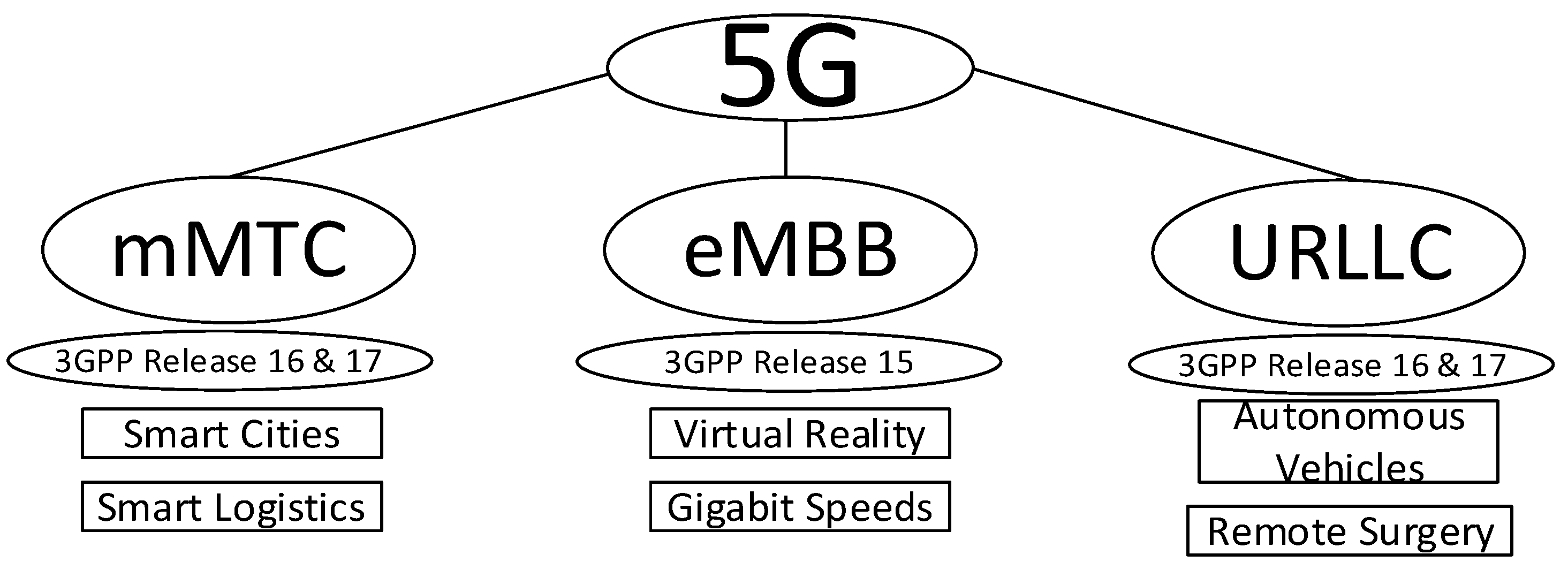
As can be seen in
Figure 1, 5G communications comprise different groups of use cases in order to support different services: Enhanced Mobile Broadband (eMBB), massive Machine-Type Communications (mMTC) and Ultra Reliable Low Latency Communications (URLLC). These groups of use cases support the concept entitled network slicing, which aims to provide to different users the requirements of the services that are being utilized. For example, autonomous vehicles require communications that are highly reliable and almost real-time, which are supported by URLLC. On the other hand, smart cities require extremely high number of devices with low power consumption, which are supported by mMTC.
The standardization process of 5G was carried out in two phases: the first phase focused on the improvement of broadband wireless cellular services (eMBB group of use case) and was defined in release 15 of third-generation partnership project (3GPP), completed in 2018, employing still part of the LTE infrastructure; the second phase, which ended in 2020, is defined in 3GPP release 16 and deals with the other two groups of use cases (URLLC and mMTC) and with the implementation of a completely new air interface, entitled 5G New Radio (NR), as well as with network slicing. Finally, 3GPP release 17 is due in 2022 and comprises different enhancements to 5G, such as improvement in URLLC, network slicing, device densification, improved capacity, etc.
An important issue of 5G within the scope of release 17, is the support of extremely high number of devices required for Smart Cities and autonomous vehicles. This brings an important limitation in terms of spectrum availability, which can be mitigated by the massive use of NOMA. It is known that the sharing of spectrum with regular power-ordered NOMA tends to be limited in terms of performance [
3], while improving the capacity. This occurs because higher power users are unable to cancel the interference generated by lower power users, representing residual interference. Cooperative NOMA aims to mitigate this limitation by making lower power users relaying, over the air, the signals of higher power users, clean of interference.
Most of the previous works [
3,
4,
5,
6,
7] comprise an isolated approach of NOMA simply using Orthogonal Frequency Division Multiplexing (OFDM), without incorporating different transmission techniques, such as Massive MIMO (m-MIMO), millimeter-wave communications (mm-wave) and block transmission techniques. The aim of this article is to consider a holistic and integrated approach with such techniques, incorporating both NOMA and Cooperative NOMA, within the 5G scenario.
Two important ingredients that allow 5G communications achieving the initial goals in terms of throughputs, spectral efficiency and network capacity are: (1) Massive MIMO [
8,
9,
10] and (2) millimeter-wave communications [
11,
12]. Employing carrier frequencies of around 60 GHz, as compared to centimeter-wave communications (e.g., 3 GHz), mm-Wave presents the advantage of having much higher channel coherence bandwidth but experiencing much higher path loss. Moreover, the very low wavelength of mm-Wave facilitates the implementation of m-MIMO, both due to the low antenna sizes and due to the low distance between MIMO antenna elements (typically 3 to 4 wavelengths for the signals in adjacent antennas to be uncorrelated). mm-Wave is specially well fitted for Vehicle-to-Everything (V2X) communications (This includes Vehicle-to-Vehicle (V2V), Vehicle-to-Infrastructure (V2I) and Vehicle-to-Pedestrian (V2P), where the link distance is low and there are demanding requirements in terms of latency, reliability and amount of data being exchanged.
Intersymbol Interference (ISI) represents the greater limitation to allow sending higher throughputs [
13]. Block transmission techniques, such as OFDM or Single-Carrier with Frequency-Domain Equalization (SC-FDE) are widely employed to mitigate it. Due to the lower Peak-to-Average Power Ratio, SC-FDE tends to be a better solution [
14]. MIMO systems is another technique that combats ISI. The combination of SC-FDE with m-MIMO results in a system that makes use of the available spectrum in a much more efficient manner.
MIMO receivers are normally associated with a high level of complexity and processing requirements, being even more demanding in case of m-MIMO. Zero Forcing (ZF) receivers require the inversion of the channel matrix for each frequency component of the channel [
15]. MRC is a receiver that can be employed to reduce the complexity, by avoiding the need to compute the inversion of the channel matrix, for each frequency component of the channel [
15,
16,
17].
With the aim of providing a potential solution for the absence of spectrum to serve extremely high number of IoT devices supported by 5G, this article focuses on the association of NOMA and Cooperative NOMA with SC-FDE and associates it with m-MIMO, using a low complexity iterative receiver. The ZF and MRC iterative receiver is utilized in this article, optimized for m-MIMO and using SC-FDE signals, as in [
17].
This article is organized as follows:
Section 2 describes the system and signal characterization for m-MIMO using SC-FDE transmissions;
Section 3 deals with the receiver design for NOMA;
Section 4 analyses the performance results and
Section 5 concludes the article.
2. System and Signal Characterization
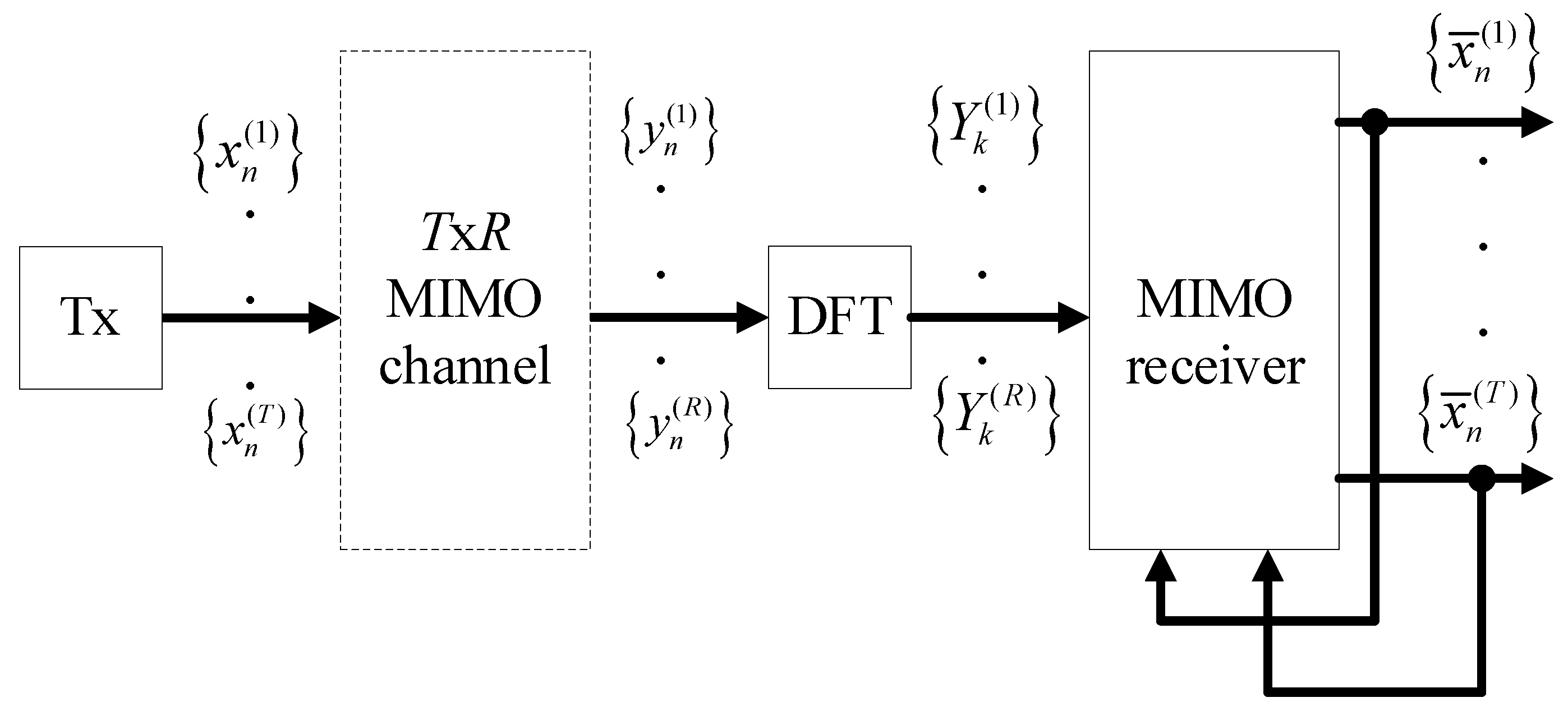
This article considers Quadrature Phase Shift Keying (QPSK) modulation, MIMO and SC-FDE signals, as depicted in
Figure 2. Since the considered MIMO is the multi-layer transmission, the number of receiving antennas
R needs to be equal to or higher than the number of transmitting antennas
T. As the number of receiving antennas
R increases, the diversity also increases, achieving better performances. It is worth noting that there are
T parallel data streams being transmitted. Consequently, an increase of the number of transmitting antennas results in an increase of the symbols rate.
The
tth antenna has a block of
N data symbols
to send.
Appendix B contains a list of symbols that can be used for clarification. At the receiver side, the received block associated with the
rth user is represented by
[
17]. As with other SC-FDE schemes, a cyclic prefix longer than the maximum overall channel impulse response is appended to each transmitted block and removed at the receiver. In this case, the corresponding frequency-domain block
satisfies
where
and where
denotes the
channel matrix for the
kth subcarrier (which is assumed invariant during the transmission of a given block), with
element
and with
. Moreover,
is the frequency-domain block channel noise for that subcarrier and
denotes the
channel matrix of the noise.
As defined in [
15], using a non-iterative receiver, the frequency domain estimated data symbols
comes:
where
is post-processing matrix of the receiver defined in [
15], separately, for the ZF and MRC, namely as
for ZF and
for the MRC.
It is known that the ZF requires a high level of computation, as it computes the pseudo-inverse of the channel matrix, for each frequency component. The MRC receiver mitigates such limitation, but it presents some level of residual interference generated in the decoding process for moderate values of , which can be mitigated by employing an iterative receiver.
Considering
R ≫ 1, which is the scenario of m-MIMO and assuming small correlation between the channels of different transmitting and receiving antennas, the elements outside the main diagonal of
are much lower than the ones at its diagonal, where
elements of the matrix
are defined for the MRC as [
15]:
For moderate values of
, the level of interference can still be representative, which can be mitigated by implementing the iterative receiver [
15]:
where
stands for the frequency domain estimated data symbols. Moreover, the interference cancellation matrix
can be computed as [
15]:
where
is an
identity matrix.
3. Receiver Design for NOMA
An advantage of power-ordered NOMA lies on the ability to allow sharing of the spectrum by different users [
3,
4,
5,
6,
7]. This characteristic represents a great advantage in scenarios where the spectrum is scarce, which is the situation of the extremely high number of IoT devices (e.g., Smart Cities or Autonomous Vehicles) supported by 5G. The signals of different users are separated in the power domain. Users closer to the base station use lower transmit powers, while users further from the base station require higher transmit powers levels. Consequently, since the signals of different users that share the spectrum present different received power levels, NOMA uses such property to differentiate signals. Naturally, besides the near-far problem, fading and power control are also factors that make received power levels of users suffer variations. Detecting the signals by their descending power levels, the NOMA receiver also takes these factors into account.
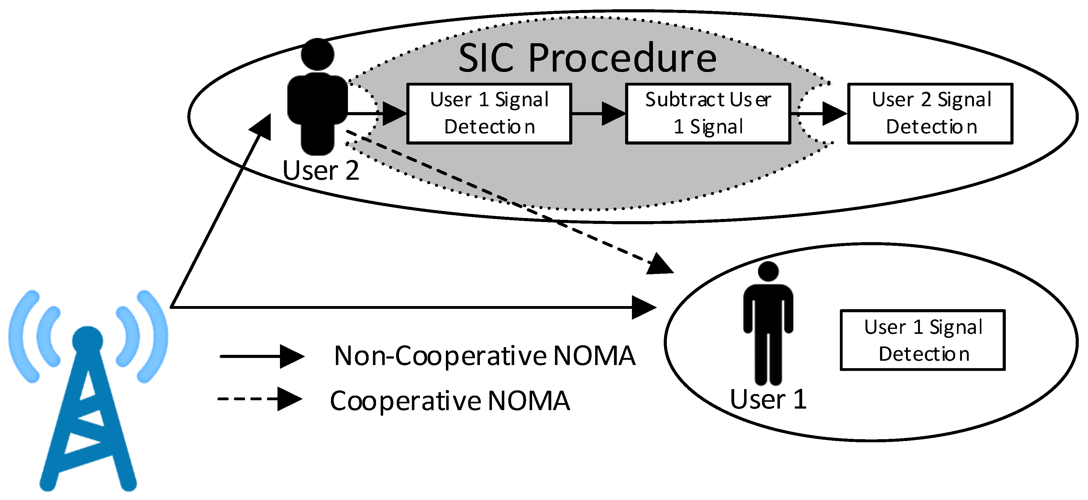
As can be seen in
Figure 3, two different scenarios exist in conventional NOMA: (1) signals with power levels higher than the reference user are estimated and cancelled using a Successive Interference Cancellation (SIC), before the reference user’s signal is detected; (2) signals with power levels lower than the reference user are not cancelled, as they represent low level of interference. Instead of conventional NOMA, cooperative NOMA can be employed. In this latter case, all interfering signals can be cancelled, including those with lower powers than the reference one.
3.1. Conventional NOMA
In conventional NOMA environment, there are two different scenarios [
3,
7]: (1) a reference user (typically closer to the base station) that presents received power level lower than that of interfering users, corresponding to the scenario where the SIC is effective as it performs the cancellation of the higher power users (typically users further from the base station); (2) a reference user with received power level higher than that of interfering users (typically further from the base station), disabling the use of the SIC (the SIC is only applicable to cancel higher power interfering users), where the lower power users represent some level of residual interference (user 1 depicted in
Figure 3). It should be referred that the SIC focuses on received power levels, which depends on several factors, such as near-far problem, fading and power control. Nevertheless, the most dominant factor is the near-far problem.
Let us assume that there are a total of
U users sharing the spectrum. The received signal at the
rth receiving antenna and
nth data symbol, is the cumulative sum of the
signals that share the spectrum (NOMA signals):
Considering only NOMA users, (1) can be re-written as:
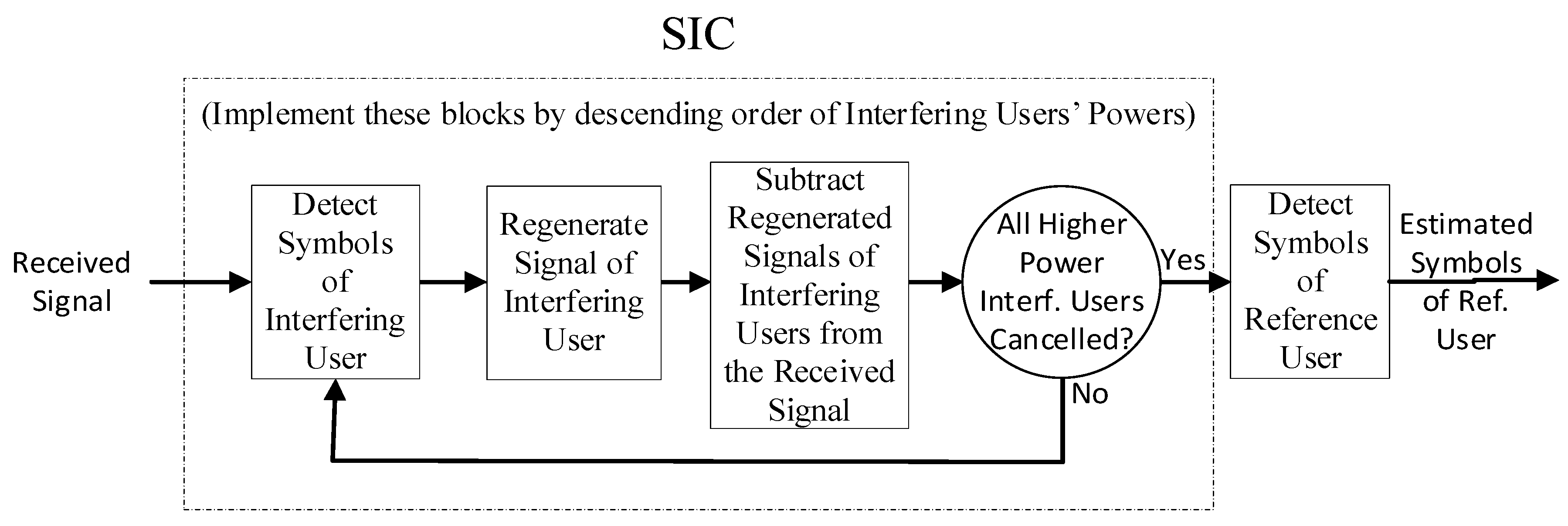
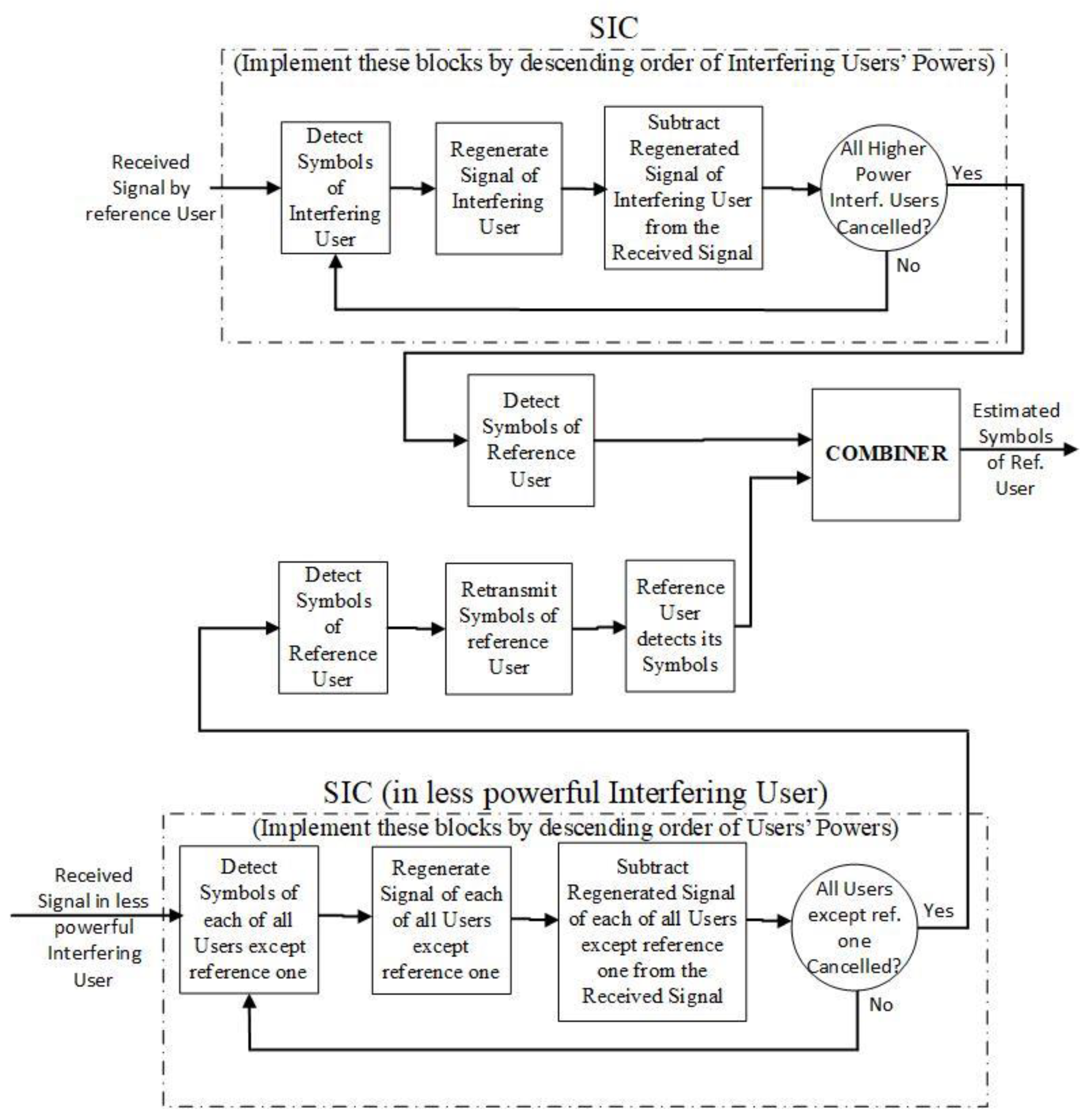
As depicted in
Figure 4, the SIC detector [
18] subtracts the interference estimated for each interfering user by their descending order of received power levels. It detects, regenerates and cancels the signal of each interfering user with power levels higher than those of the reference user. Due to its descending received power order of cancellation, all weaker users benefit from the fact that stronger users are cancelled first. Furthermore, it leads to a better acquisition and more accurate detection of higher power signals and so, take advantage of users with different powers. The signal
at the output of the SIC, for the
nth data symbol, after the cancellation of the higher power users
U′, comes:
where
stands for the estimate of the received signal of the
ith interfering user and
nth data symbol.
In case the reference user presents higher power, the SIC is not able to cancel interference and the lower power users represent residual interference. Note that the SIC introduces a delay in the signal corresponding to one symbol period for each cancellation stage, i.e., for each cancelled user. Assuming, e.g., that the reference user is the third more powerful user, this means that the two more powerful users need to be cancelled, introducing a delay of two symbol periods in the signal detection. However, these delays can be reduced if a fast processing is employed (in general, we can have a single symbol delay (to receive the full block) plus the processing delay for each iteration, with the later dependent on the signal processing approach)
3.2. Cooperative NOMA
With conventional NOMA, higher power users are unable to cancel the interference generated by lower power users, representing residual interference. As seen in
Figure 3, Cooperative NOMA aims to mitigate this limitation by making lower power users relaying, over the air, the signals of higher power users, clean of interference. The higher power users can use any algorithm to combine such relayed signal(s) with the one received directly from the base station [
18]. We assume the relay of type decode and forward.
As seen in
Figure 3, assuming that user 1 is the reference one (higher power user) and that user 2 is an interfering user (lower power user), as in the case of conventional NOMA, user 2 employs the SIC for subtracting the signal of user 1 from the overall received signal (using the SIC), before user 2 is detected. Cooperative NOMA considers that interfering users (user 2, in the case of
Figure 3) relay, over the air, the signals detected by the SIC (user 1, in the case of
Figure 3). As depicted in
Figure 5, this allows that a user with higher received power level (user 1, in the case of
Figure 3) receives several copies of its signal: (a) the signal received directly from the base station, where the interference created by lower power users cannot be cancelled by the SIC; (b) the signal relayed by the other interfering users (user 2, in the case of
Figure 3), which can be clean of interference of lower power users. Let us focus on
Figure 3. User 2 signal is assumed presenting lower power and, once detected, can be regenerated and cancelled from the overall signal of user 1, before it is relayed, as this is a matter of introducing an additional iteration. The signal of user 1 (higher power user) can then be relayed over the air. The several copies of signals of user 1 (higher power) can then be combined at the data symbol level
, using any combining algorithm.
As previously described, the SIC introduces a delay in the signal corresponding to one symbol period for each cancellation stage, i.e., for each cancelled user. In the case of the cooperative NOMA, the number of parallel SIC employed correspond to the number of less powerful interfering users than the reference user, added with the SIC of the reference user. The worst case, in terms of delay, corresponds to the less powerful interfering user (one of the interfering users that relay the detected signal), which cancels all the other users, introducing a delay of one symbol period for each user. This delayed and relayed signal is then combined with the signal of the reference user (clean of the interference of higher power users). Therefore, cooperative NOMA introduces a delay corresponding to the worst-case scenario, which is a delay of one symbol period for each of the users that share the spectrum with the NOMA technique minus one. Assuming that the number of NOMA users is U, the delay introduced by cooperative NOMA corresponds to U-1 symbol periods. Comparing the delay of the NOMA with that of the cooperative NOMA, it is viewed that while NOMA only introduces a delay corresponding to the number of higher power users, cooperative NOMA introduces a delay corresponding to the number of NOMA users that share the spectrum minus one.
In terms of complexity, while conventional NOMA has a single receiver with the SIC to cancel the higher power interfering users, cooperative NOMA must incorporate a similar receiver added with multiple parallel receivers to detect those signals that have been relayed over-the-air. In the worst case, this corresponds to the number of interfering users with power lower than the reference one. Naturally that a trade-off can be achieved between complexity and performance. In this context, a cooperative NOMA receiver can only incorporate one or two parallel receivers to detect the signals that have been relayed over-the-air by one or two less powerful users.
We now focus on the combination of the different received replicas, weighted by the corresponding reliabilities, which is associated with the Mean Squared Error (MSE). Using the estimates of
cm (that is
), which stands for the output training symbol vector from the
mth receive branch, the data symbol
, resulting from the
M (receive) branches becomes [
19]:
where
is the signal obtained using
(as defined by (8), after soft or hard decision, from the
mth transmission (the signal received directly from the base station or those that have been relayed by the other users).
4. Performance Results
This section studies the performance results, namely the Bit Error Rate (BER) obtained with NOMA, associated to m-MIMO. Two types of NOMA are studied: conventional NOMA and Cooperative NOMA. We assume ideal channel estimation and the block transmission technique SC-FDE. The BER is evaluated as a function of
, where
is the energy of the received bits and
is the one-sided power spectral density of the noise. This performance was evaluated using Monte Carlo simulations, with QPSK modulation and with a block length of
N = 256 symbols (similar results were observed for other values of
N, provided that
N >> 1). A Rayleigh fading channel was considered with 16 uncorrelated equal power paths. The duration of the useful part of the blocks (N symbols) is 1μs and the cyclic prefix has a duration of 0.125 μs. In our paper we considered a carrier frequency of 5 GHz, but the adopted signal processing schemes could be successfully employed regardless of the adopted carrier frequency. Four iterations of the MRC receiver were assumed to detect the MIMO signals using SC-FDE transmission technique (detection and interference cancellation) [
17]. Beyond four iterations, the performance improvement was almost negligible. MIMO using spatial multiplexing (multi-layer transmission) is adopted. In this sense, results with
Tx
R (
T transmitting antennas and
R receiving antennas) mean that there are
T parallel flows of symbols (the symbols rate increases
T times). As in the case of the MIMO multi-layer transmission,
R needs to be equal to or higher than
T, for the detection to be possible. It is worth noting that the SIC, as part of the NOMA receiver, focuses on received power levels, which depend on several factor, such as the near-far problem, fading and power control. Consequently, the reference to distances is only used for description purposes of different scenarios, but the same applies to the other factors, such as fading and power control, that influences the variation of the received power levels.
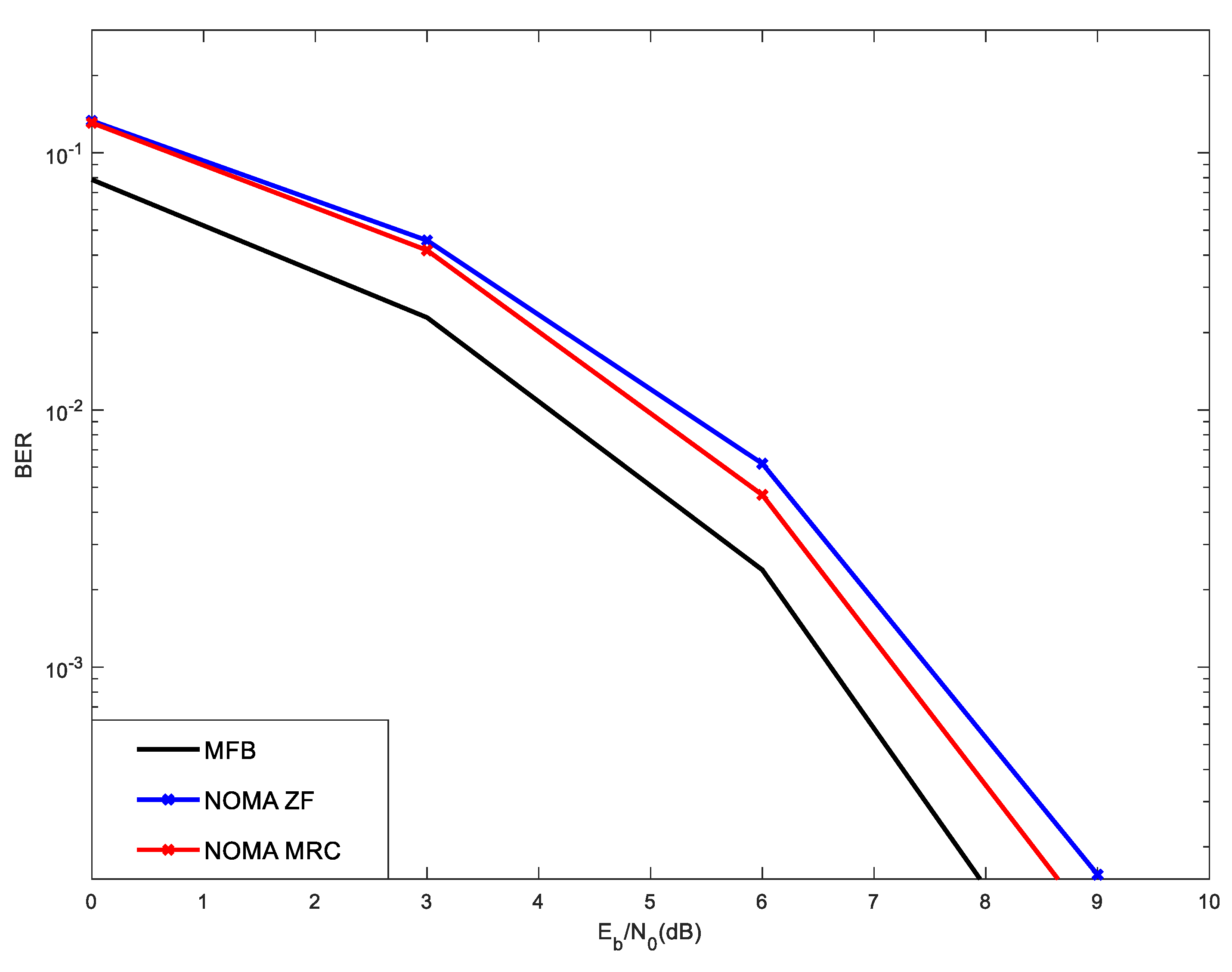
Figure 6 shows the performance results for conventional NOMA (designated in figures as “NOMA”) and Cooperative NOMA (designated in figures as “COOP NOMA”), with 4 × 32 MIMO, considering two receivers: ZF and MRC. Two NOMA users were considered in the simulation, with receive power levels [1 0.5], where the first value in the vector [1 0.5] (1, in this case) corresponds always to the power of the reference user, being the other value the power of the interfering user (0.5, in this case). In this scenario, the power of the interfering user is 3 dB lower than that of the reference user. Weak users are those that tends to be further from the base station (can also be due to e.g., fading) and, therefore, the propagation losses are higher. With NOMA, this is mitigated by employing higher transmit power. Therefore, it is assumed that the interfering user with transmit power 0.5 tends to be closer to the base station than the reference user, whose transmit power is 1.
As can be seen, the results of
Figure 6 obtained with conventional NOMA are quite limited, due to the existence of residual interference. Noteworthy is that the SIC that is part of the receiver only detects, regenerates and cancels users’ signals with powers higher than those of the reference user, which is not the case here (the interfering user has power 0.5, which is not cancelled). This explains the low performance achieved with conventional NOMA, for both ZF and MRC. It is also viewed that, with conventional NOMA, the ZF performs better than the MRC. However, the MRC consists of an iterative receiver that estimates the transmitted symbols and aims to improve such estimate in each iteration. With high level of interference associated with the non-cancelled interfering NOMA user, the symbol estimates performed in each iteration of the MRC receiver is poor and therefore, it is not able to perform well. On the other hand, even with the noise enhancement typical of the ZF receiver [
17], it performs better than that of the MRC.
Cooperative NOMA comprises the cancellation of the interfering signals associated with all users and exploits diversity. Cooperative NOMA considers that the lower power users retransmit the symbols detected by the SIC of higher power users (typically using decode and forward, in Time Division Multiplexing). These additional signals are utilized by higher power users to exploit diversity, as the same signals are also received directly from the base station (assuming downlink) and a copy of them (clean of interferences) is relayed by the lower power users. These signals are combined to improve performance.
Figure 6 shows that such combination of signals performed with the Cooperative NOMA results in a good performance improvement, when compared with conventional NOMA, for both MRC and ZF, whose performances are close to that of the Match Filter Bound (MFB). Note that the MFB curve is a way to measure the channel modelled by the sum of delayed and independently Rayleigh-fading rays, which can be viewed as a lower bound.
Figure 6 also evidences that, with Cooperative NOMA, the MRC performs better than the ZF. This derives from the fact that Cooperative NOMA allows the cancellation of all NOMA interference (not only of users with higher receive power levels) and, additionally, allows exploiting diversity. This lower level of interference allows the iterative MRC receiver to improve the symbol estimates in different iterations. On the other hand, the performance of the ZF is limited, as this receiver presents noise enhancement. Furthermore, the level of complexity of the ZF is substantially higher than that of the MRC, as it requires the computation of the pseudo-inverse of the channel matrix for each frequency component.
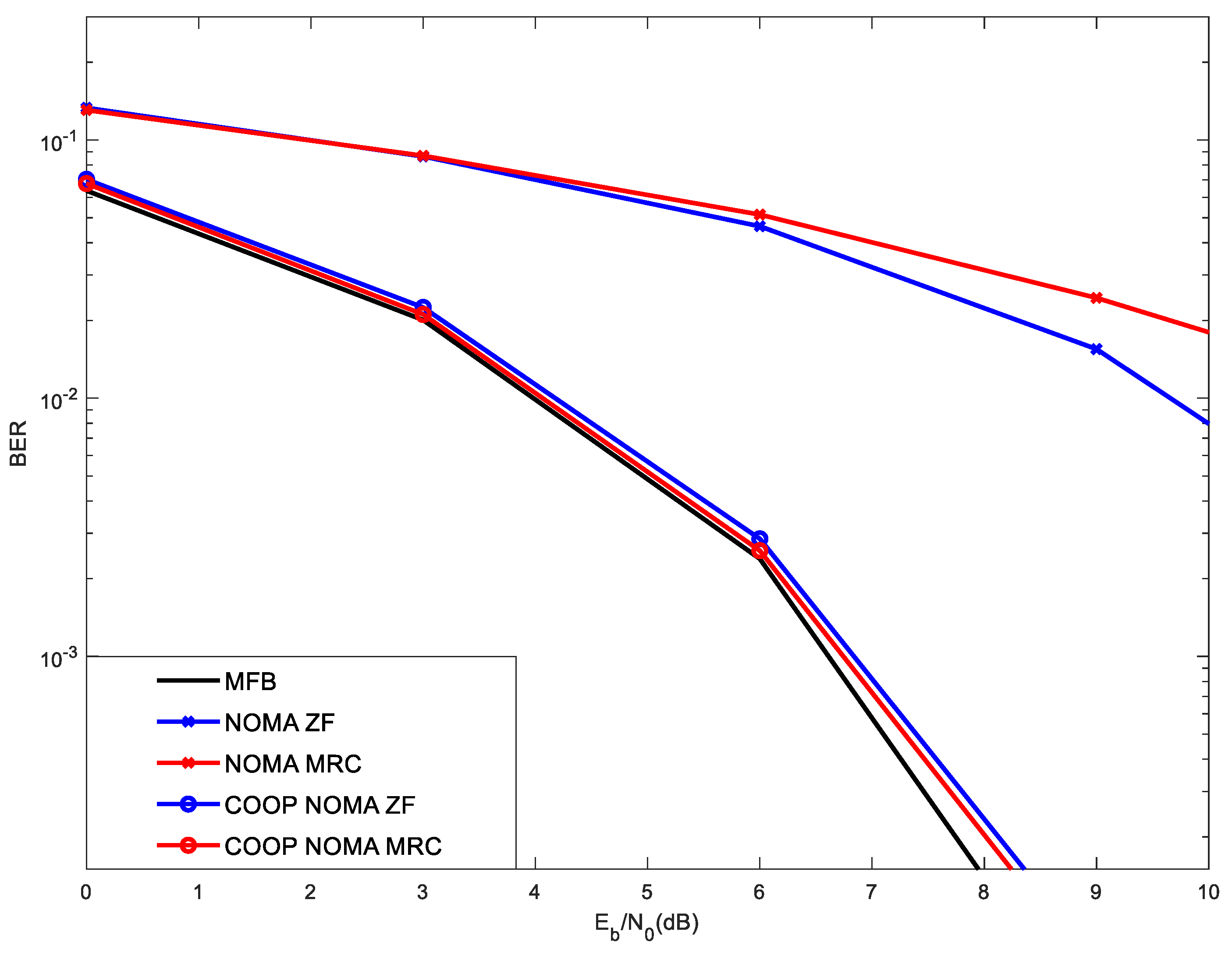
Figure 7 shows the BER performance in the same scenario as that of
Figure 6 with the difference that the power of users is [0.5 1]. In this scenario, the reference user tends to be closer to the base station (power 0.5), while the interfering user tends to be further from the base station (power 1). As previously mentioned, we refer to the distance from the base station only for explanation purposes, as the fading or the power control can also make the received power suffer variations. Noteworthy is that the conventional NOMA receiver comprises the detection, regeneration and cancellation of the users’ signals by their descending order of powers (up to the power of the reference user), before the detection of the reference user takes place. Consequently, the detection of the reference user tends to be clean of interferences and the performance achieved with conventional NOMA is already good. In this scenario, since the reference user presents a power level (e.g., 0.5) which is 3 dB lower than the interfering user (e.g., 1), such signal detection is not carried out in the SIC receiver of the interfering user and Cooperative NOMA is not implemented, as it does not bring any added value. Moreover, note due to its lower power, the SIC of the reference user, using the mode of conventional NOMA, is now able to cancel the interfering signal, as the power of the interfering user is higher, making the effectiveness of cooperative NOMA useless.
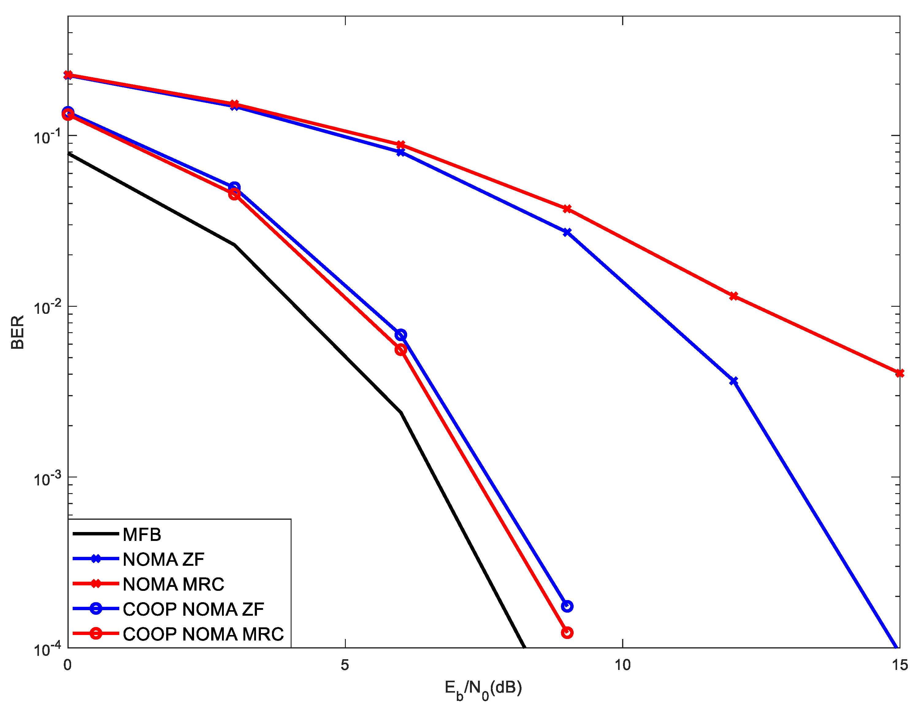
Figure 8 shows the performance results for conventional NOMA against those of Cooperative NOMA, for the scenario with four users sharing the spectrum with NOMA, with powers [1 0.5 2 4] (1 stands for the power of the reference user, while 0.5, 2 and 4 stands for the power of the interfering users). The MIMO with 4 transmitting antennas and 32 receiving antennas is considered. As in
Figure 6, due to the existence of interference that is not cancelled by the SIC (lower power user, i.e., the one with power 0.5), the performance obtained with conventional NOMA is quite poor, as it contaminates the correct estimates of the high-power users. Moreover, due to the residual interference, results obtained with the iterative MRC receiver are worse than those obtained with the ZF. Nevertheless, when comparing Cooperative NOMA against conventional NOMA, we observe a performance gain, due to its ability to cancel all interfering users (not only those with higher power) and due to the existence of diversity. However, in this case, the interfering user, with lower power level, retransmits a copy of the signal of the reference user (clean of interference), which is combined with the one received directly. Once again and considering Cooperative NOMA, the MRC receiver outperforms the ZF. It is worth noting that Cooperative NOMA brings added value for users that present higher power levels, which corresponds typically to users further from the base station.
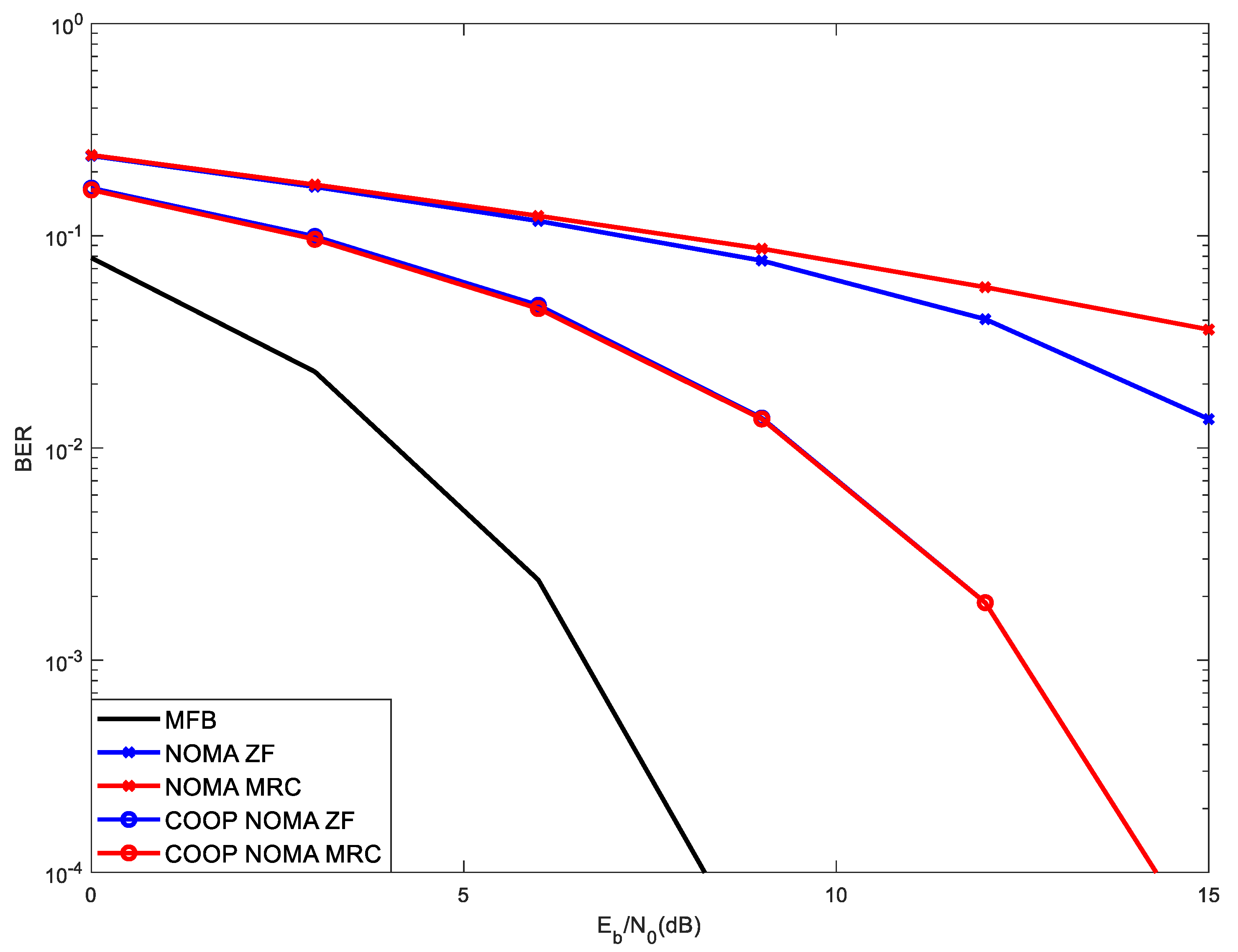
Figure 9 shows the performance results for conventional NOMA against those of Cooperative NOMA, for the situation of five users sharing the spectrum using NOMA, with powers [2 1 0.5 4 8] (2 stands for the power of the reference user, while 1, 0.5, 4 and 8 stands for the power of the interfering users). Due to the higher number of interfering NOMA users and due to the existence of two lower power interfering users that are not cancelled by the SIC of Conventional NOMA, such performance is limited due to a noise floor. As before, in this scenario, the MRC is not able to achieve an acceptable performance, presenting lower performance than the ZF. Nevertheless, when observing the results of Cooperative NOMA, a high-performance improvement is registered as compared with Conventional NOMA and the iterative MRC receiver similar to the ZF receiver.
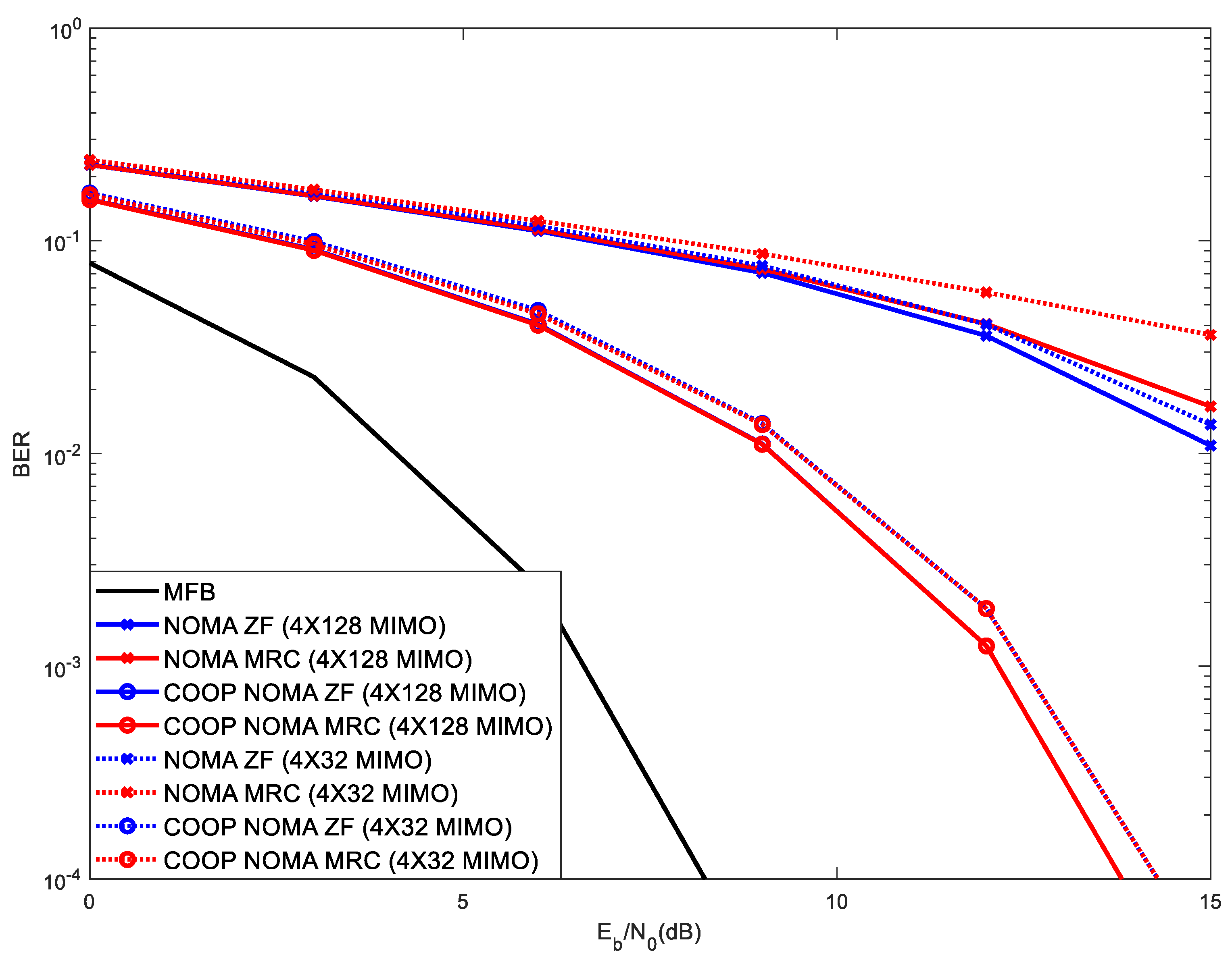
Figure 10 shows results in the same scenario as those of
Figure 9, making a comparison between 4 × 128 MIMO against 4X32 MIMO, with 5 NOMA users with received power levels [2 1 0.5 4 8] (2 is the received power of the reference user). As expected, due to higher level of diversity, 4 × 128 MIMO outperforms 4 × 32 MIMO. Therefore, the use of higher MIMO diversity can be viewed as a mechanism to mitigate the degradation of performance that results from a higher number of NOMA users. In other words, the increase of NOMA users can be compensated by employing a higher number of MIMO receiving antennas.
5. Conclusions
NOMA is an effective mechanism to accommodate a higher number of users without an increase of spectrum. This translates in a higher spectral efficiency, being especially useful in 5G scenarios where the spectrum is scarce, such as with extremely high number of IoT devices, like in future smart cities or autonomous vehicles. Nevertheless, as the number of NOMA users increases, a degradation of the BER performance tends to occur, especially for users that have higher receive power levels. Cooperative NOMA brings special added value for users with received higher power levels. With conventional NOMA, the SIC only detects, regenerates and cancels users’ signals with power levels higher than those of the reference one and those with less received power levels are not cancelled, representing residual interference and degrading the performance. Since Cooperative NOMA allows the cancellation of the other interfering users and provides diversity, the performance tends to improve, especially for users with higher received power levels.
When Cooperative NOMA is adopted, associated with m-MIMO, the MRC receiver tends to outperform the ZF and its complexity is lower than that of ZF. It was viewed that the degradation of performance that results from the increase of NOMA users can be mitigated by the increase of MIMO diversity.
Finally, it was concluded that the combination of NOMA/Cooperative NOMA with m-MIMO, using SC-FDE signals and with the low complexity MRC receiver, is a good combination to achieve future evolutions of 5G.


