Abstract
This letter proposes a novel design for a printed 5G monopole antenna on a vehicle window glass. The proposed antenna consists of a coplanar waveguide (CPW), a monopole radiator, parasitic elements, and a lattice-structure reflector. The parasitic elements are placed on either side of the monopole radiator to improve the bore-sight gain. To solve the radiation pattern distortion problem that occurs due to the thick vehicle window glass, the lattice-structure reflector is printed on the opposite side of the monopole radiator. Through fabrication and measurement of the proposed antenna, it is confirmed that the design improves bore-sight gain, and minimizes the radiation pattern distortion. The results demonstrate that the proposed 5G monopole antenna with parasitic elements and the lattice-structure reflector is suitable for 5G communication in vehicle applications.
1. Introduction
With the dramatic development of wireless communication technology, interest in vehicle communication systems has been increasing considerably in various applications, such as autonomous driving [1,2,3], telematics service [4,5,6], and vehicle-to-everything (V2X) communications [7,8,9,10,11]. In recent years, these systems require 5G wireless communication technology for high-throughput and low-latency in an ever-changing communication environment. In particular, for vehicle applications, it is significantly important to employ high-gain 5G antennas to maintain a stable 5G communications link while driving. Many studies have investigated the use of conventional antenna structures, i.e., patch antennas [12], dipole antennas [13,14], and dielectric resonator antennas [15] in 5G vehicle antenna designs. In some cases, research has attempted to apply such conventional antennas to actual vehicles using additional structures; for example, the vehicle roof is re-designed and modified to construct a cavity structure for mounting a 5G inverted-F monopole antenna [16]. Although these antennas have shown high antenna performances, the need to modify the vehicle structure or add new structures to the vehicle creates a disadvantage for their adoption as 5G wireless vehicle communication systems. To resolve these problems, a number of antenna designs that directly print the antennas onto the vehicle window glass have been reported, for example, mesh-grid strip line patterns [17], horizontal strip line patterns [18], and printed inverted-F antenna [19]. However, in general, on-glass antennas have been employed for low-frequency band applications below 1000 MHz, such as amplitude modulation broadcasting (AM), frequency modulation broadcasting (FM), and digital multimedia broadcasting (DMB). In addition, the linear polarization (LP) characteristic is essential for 5G vehicle communications. Thus, there needs to be more in-depth research to develop glass-printed antennas with monopole radiators to achieve the LP property.
In this paper, we propose a printed 5G monopole antenna on the vehicle window glass using parasitic elements and a lattice-structure reflector for gain enhancement. The proposed antenna consists of a coplanar waveguide (CPW), a monopole radiator, parasitic elements, and a lattice-structure reflector. The CPW is used as a feeding line instead of other transmission lines because guided fields are not induced inside the thick vehicle window glass. The monopole radiator is directly connected to the CPW inner line, and then the multiple rectangular parasitic elements surrounding the monopole are designed to enhance the bore-sight gain. The lattice-structure reflector, composed of multiple patches, is printed onto the opposite side of the monopole radiator to minimize pattern distortion. Herein, the pattern distortions resulting from thick vehicle window glass can be adjusted by the number and dimension of the reflector elements. The proposed antenna is modeled and optimized using the CST Studio Suite full EM simulation software [20]. To verify the feasibility, the proposed antenna is fabricated, and measured in a full anechoic chamber to obtain its performances, such as gains, reflection coefficients, and radiation patterns. The results confirm that the proposed antenna printed on thick vehicle window glass is suitable for 5G vehicle applications with improved gain and low pattern distortion.
2. Proposed Antenna Design
2.1. Geometry of Vehicle Window Glass Antenna
Figure 1 shows the geometry of the proposed printed 5G monopole antenna on the vehicle window glass with the parasitic elements and lattice-structure reflector to improve the bore-sight gain and minimize the radiation pattern distortion. The proposed antenna consists of the CPW feeding structure, the monopole radiator with parasitic elements, and the lattice-structure reflector. The CPW has an inner conductor (length l2 × width w4) and grounds (length l2 × width w2). The gap between the inner conductor and grounds is g1. The CPW is printed on the top of the thick vehicle window glass substrate (εr = 6.9, tanδ = 0.017 at 28 GHz) with dimensions of w1 × l1 × t (width × length × thickness). Note that the guided fields from the CPW line are less affected by substrate thickness compared to other transmission lines (i.e., strip line, microstrip, and CPW with a ground) that induce more electromagnetic fields inside the substrate. This CPW line is fed by a K-type (2.92 mm) connector [21], and we modeled the actual geometry to consider the effects of the connector, as shown in Figure 2. The K-type connector is excited by using a waveguide port at the starting points of the inner and outer conductors, which is directly connected to the coaxial cable, to feed the CPW in the simulation conditions. The monopole radiator is directly connected to the CPW inner conductor and has a length of l4 and a width of w4 for resonance at 28 GHz. This monopole has the LP characteristic that can have advantages for the design and fabrication of an antenna, and in general, it is widely employed for 5G vehicular communications [22,23,24,25]. The parasitic elements have four rectangular patches (l3 × w3) that are placed at the distances g1 and g2 from the monopole radiator and the CPW ground, respectively. When adjusting these dimensions, the parasitic elements operate as a radiator by indirect coupling with the monopole radiator. Furthermore, the electromagnetic waves radiated from each parasitic element can be combined with those radiated from the monopole radiator that results in increasing the bore-sight gain. The lattice-structure reflector is printed on the opposite side of the monopole radiator. The reflector is composed of multiple square patches with a width of w5, and the distance between the adjacent patches is g3. The number of reflector elements is M × N, where M and N indicate the total number of reflector patches along the x- and y-axes. The adjustment of the reflector parameters can effectively minimize the radiation pattern distortion that occurs due to the thick vehicle window glass in accordance with the wavelength at 28 GHz. Herein, design goals for this work are as follows: operating center frequency of 28 GHz, bandwidth of more than 850 MHz, reflection coefficient less than −10 dB, bore-sight gain of more than 0 dBi, LP, and glass substrate thickness of 3.2 mm. To achieve the goals, the proposed antenna was modeled and optimized using the CST Studio Suite full EM simulator, and the optimized design parameters are listed in Table 1.
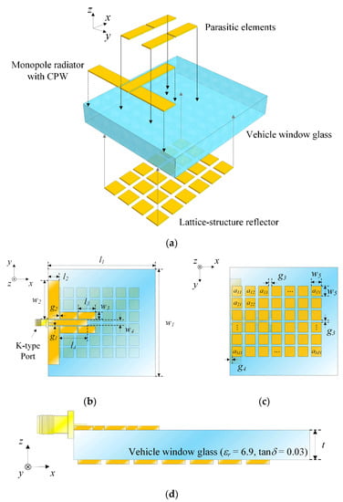
Figure 1.
Geometry of the proposed printed antenna: (a) isometric view; (b) top view; (c) bottom view; (d) side view.
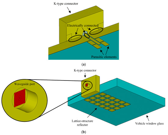
Figure 2.
The actual connector model with a waveguide port in the CST EM simulation software: (a) a feeding connection part; (b) a waveguide port excitation part.

Table 1.
Optimized design parameters of the proposed antenna.
2.2. Fabrication and Measurement
Figure 3 shows photographs of the fabricated 5G monopole antenna with the parasitic elements and the lattice-structure reflector on vehicle window glass. In general, glass antennas are fabricated or printed on vehicle glass using a silk-screen method [17] or an epoxy resin adhesive. However, such methods have low conductivity in the electrical connection, poor manufacturing tolerance, and low thermal durability in the fabrication of the glass antenna. To solve these problems, the proposed antenna is fabricated by etching the copper layer and employing a thermosetting adhesive to strongly stick the copper patterns to vehicle window glass. The proposed antenna is directly fed by the K-type (2.92 mm) connector, and the inner and outer conductors of the feeder are electrically connected to CPW by soldering. Note that the actual K-type connector is modeled and excited by using a waveguide port at the starting points of the inner and outer conductors to feed the CPW in the simulation conditions. On the bottom of the vehicle window glass, which is electrically isolated from the antenna feeder, the lattice-structure reflector patches are printed. To confirm feasibility, the fabricated antenna is measured in a full anechoic chamber to obtain the antenna characteristics, such as gains, reflection coefficients, and radiation patterns. To minimize the cable effects, a jig with a low dielectric constant is used to stand the proposed antenna in the air of the anechoic chamber, where the cable is connected to the K-type connector with the jig. In addition, the thick vehicle window glass substrate is measured to obtain the specific EM characteristics according to the frequency of the measurement setup, as shown in Figure 4. The measured dielectric constant (εr) and loss tangent (tanδ) are 6.9 and 0.017 at 28 GHz, respectively, and then the measured results are employed as input parameters to simulate the proposed antenna. Figure 5 presents the measured (solid line) and simulated (dashed line) reflection coefficients of the proposed antenna. The measured reflection coefficients agree well with the simulated results, and the values at 28 GHz are −20 dB and −15.6 dB, respectively. Figure 6 presents the bore-sight gain of the proposed antenna with and without parasitic elements. The proposed antenna with the parasitic elements has measured and simulated bore-sight gains of 2 dBi and 1.6 dBi at 28 GHz, while the simulation result of the vehicle window glass antenna without the parasitic elements is 0.3 dBi. In addition, the gain bandwidth over 0 dBi increases from 1.7 GHz to 3 GHz, according to the existence and absence of the proposed parasitic elements. The gain of the proposed antenna seems to be slightly lower than that of conventional monopole antennas due to the high dielectric loss of the thick vehicle glass. It results in the radiation efficiency of 33.68% at 28 GHz, but this radiation efficiency can be enhanced when the dielectric loss of the antenna substrate becomes lower. Figure 7 illustrates the measured and simulated radiation patterns in zx- and zy-planes at 28 GHz and 29 GHz, where the solid line and dashed line indicate the measured and simulated results, respectively. The measured half power beam widths are 42° and 64° in the zx- and zy-planes at 28 GHz. The measured maximum gains are 2.3 dBi and 2.1 dBi at angles of −25° and −1° in the zx- and zy-planes at 28 GHz, respectively. The measured radiation patterns are in good agreement with the simulated radiation patterns at 29 GHz. Figure 8 illustrates the 3D radiation patterns of the proposed antenna according to the frequency to observe the maximum gains. The maximum gains of the proposed antenna are 0.3 dBi, 3.2 dBi, and 3.4 dBi at 26 GHz, 28 GHz, and 30 GHz, respectively. To confirm the feasibility, the antenna characteristics such as the operating frequency band, the maximum gain, the antenna dimensions, and the substrate material of the proposed antenna are compared to those of previous studies, as listed in Table 2.
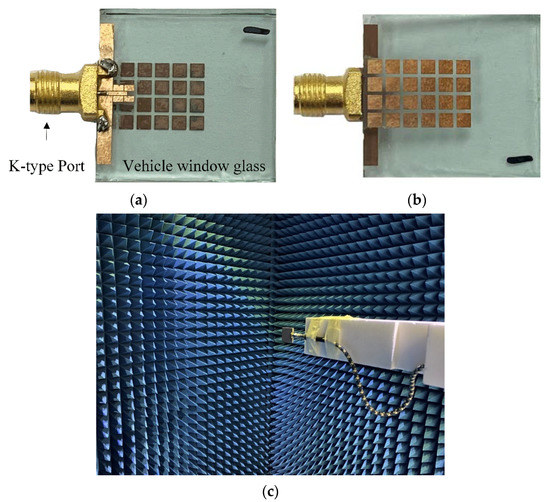
Figure 3.
Photographs of the proposed antenna and measurement setup: (a) top view; (b) bottom view; (c) measurement setup.
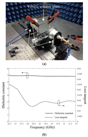
Figure 4.
The measured EM characteristics of the thick vehicle window glass substrate: (a) measurement setup; (b) dielectric constant and loss tangent according to the frequency.
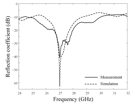
Figure 5.
Reflection coefficient of the proposed antenna.
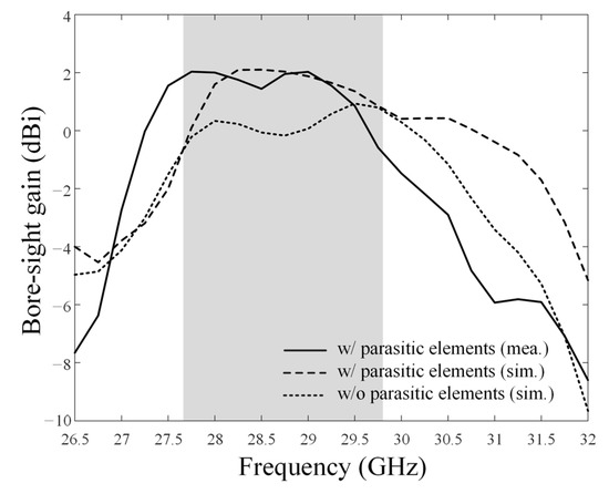
Figure 6.
Measured and simulated bore-sight gains of the proposed antenna with and without parasitic elements.
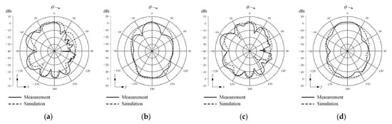
Figure 7.
Measured and simulated radiation patterns of the proposed antenna: (a) zx-plane at 28 GHz; (b) zy-plane at 28 GHz; (c) zx-plane at 29 GHz; (d) zy-plane at 29 GHz.
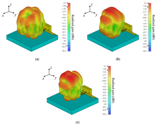
Figure 8.
Three-dimensional patterns: (a) at 26 GHz; (b) at 28 GHz; (c) at 30 GHz.
Table 2.
Comparisons of antenna characteristics.
2.3. Analysis and Verification
Figure 9 shows the bore-sight gain results according to the number of reflector patches. The M and N values are varied from 3 to 9 to observe the gain properties of the proposed antenna. The resulting maximum bore-sight gain of 1.6 dBi is observed when the patches of the lattice-structure reflector are arranged with a 4 × 6 (M × N) planar array. We further examine the gain characteristics by changing other reflector patch parameters to obtain the optimum bore-sight gain. Figure 10a illustrates the bore-sight gain in accordance with the gap between and the width of the reflector patches. In the fixed 4 × 6 (M × N) arrangement, the bore-sight gain is observed to be in the ranges of 1.5 mm ≤ w5 ≤ 2.5 mm and 0.1 mm ≤ g3 ≤ 0.9 mm. The increment of the reflector patch width usually improves the bore-sight gain, while that of the gap reduces the bore-sight gain. In addition, these parameters can adjust the reflection coefficients for impedance matching characteristics, as shown in Figure 10b. When w5 is less than 2 mm, and g3 is more than 0.5 mm, impedance matching for the proposed antenna improves. From the results, the optimal values for parameters w5 and g3 of the lattice-structure reflector can be determined to be 2 mm and 0.5 mm. Furthermore, a patch width of w5 can improve the bore-sight gain through the minimization of the pattern distortion, and there is another key design parameter of w3 that can adjust the impedance matching characteristic of the proposed antenna. In addition, we simulate the proposed antenna mounted on an actual vehicle model to observe the vehicle platform effects. The partial vehicle model, where the dimensions were over 20 wavelengths at 28 GHz, is used to analyze the radiation characteristics of the proposed antenna due to the limited computational resources. Figure 11a illustrates the simulated 3D radiation patterns according to the mount location of the proposed antenna: front, rear, left side, and right side of the vehicle window. The radiation patterns of the proposed antenna with the vehicle platform are similar to those of the stand-alone antenna, but it has small fluctuations due to the ground effect, as can be seen in Figure 11b. The results confirm that the proposed antenna is feasible for 5G communication in vehicle applications with high gain performance by optimizing the parasitic elements and the lattice-structure reflector.
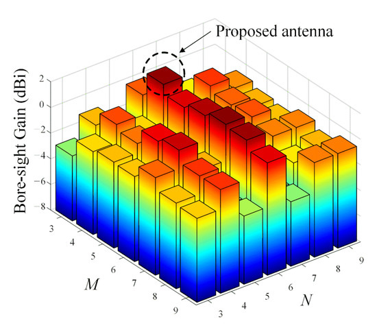
Figure 9.
Bore-sight gain in accordance with variations of the number of reflectors.
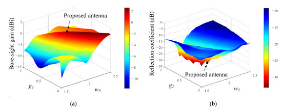
Figure 10.
Bore-sight gain and reflection coefficient in accordance with the variations of parameters w5 and g3: (a) bore-sight gain; (b) reflection coefficient.
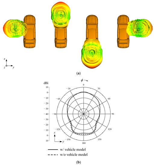
Figure 11.
Simulated radiation patterns of the proposed antenna considering the vehicle platform effects: (a) 3D patterns according to the mount location; (b) 2D radiation patterns with and without the vehicle model.
3. Conclusions
We investigated the novel design of a printed 5G monopole antenna with the parasitic elements and the lattice-structure reflector on the vehicle window glass. The parasitic elements were placed on either side of the monopole radiator to improve the bore-sight gain. To solve the radiation pattern distortion problem that occurs due to the thick vehicle window glass, the lattice-structure reflector was printed opposite to the monopole radiator. The proposed antenna had a measured reflection coefficient of −20 dB, and a bore-sight gain of 1.6 dBi at 28 GHz. The results demonstrated that the proposed 5G monopole antenna with the parasitic elements and the lattice-structure reflector was suitable for 5G communication in vehicle applications. In future work, more design considerations such as the large window glass and delicate fabrication process might be needed for practical use of the proposed antenna.
Author Contributions
Conceptualization, C.I., T.-H.L., D.J., N.-K.K. and H.C.; methodology, C.I., T.-H.L. and D.J.; software, C.I.; validation, C.I., T.-H.L., D.J. and H.C.; formal analysis, C.I., T.-H.L., D.J. and H.C.; investigation, C.I., T.-H.L. and D.J.; resources, C.I.; data curation, C.I.; writing—original draft preparation, C.I., T.-H.L., D.J. and H.C.; writing—review and editing, C.I., T.-H.L., D.J. and H.C.; visualization, C.I.; supervision, H.C.; project administration, H.C.; funding acquisition, N.-K.K. and H.C. All authors have read and agreed to the published version of the manuscript.
Funding
This research received no external funding.
Institutional Review Board Statement
Not applicable.
Informed Consent Statement
Not applicable.
Data Availability Statement
Not applicable.
Acknowledgments
This work was supported by the HYUNDAI Motors, the Basic Science Research Program through the National Research Foundation of Korea (NRF) funded by the Ministry of Education (no. NRF-2017R1A5A1015596), and the NRF grant funded by the Korea government (no. 2015R1A6A1A03031833).
Conflicts of Interest
The authors declare no conflict of interest.
References
- Chekired, D.A.; Togou, M.A.; Khoukhi, L.; Ksentini, A. 5G-slicing-enabled scalable SDN core network: Toward an ultra-low latency of autonomous driving service. IEEE J. Sel. Areas Commun. 2019, 37, 1769–1782. [Google Scholar] [CrossRef]
- Wang, Y.; Wei, H. Road capacity and throughput for safe driving autonomous vehicles. IEEE Access 2020, 8, 95779–95792. [Google Scholar] [CrossRef]
- Ren, K.; Wang, Q.; Wang, C.; Qin, Z.; Lin, X. The security of autonomous driving: Threats, defenses, and future directions. Proc. IEEE 2020, 108, 357–372. [Google Scholar] [CrossRef]
- Tian, D.; Zhou, J.; Wang, Y.; Lu, Y.; Xia, H.; Yi, Z. A dynamic and self-adaptive network selection method for multimode communications in heterogeneous vehicular telematics. IEEE Trans. Intell. Transp. Syst. 2015, 16, 3033–3049. [Google Scholar] [CrossRef]
- Siami, M.; Naderpour, M.; Lu, J. A mobile telematics pattern recognition framework for driving behavior extraction. IEEE Trans. Intell. Transp. Syst. 2021, 22, 1459–1472. [Google Scholar] [CrossRef]
- Wahlström, J.; Skog, I.; Händel, P. Smartphone-based vehicle telematics: A ten-year anniversary. IEEE Trans. Intell. Transp. Syst. 2017, 18, 2802–2825. [Google Scholar] [CrossRef] [Green Version]
- Liu, K.; Ng, J.K.; Wang, J.; Lee, V.C.S.; Wu, W.; Son, S.H. Network-coding-assisted data dissemination via cooperative vehicle-to-vehicle/-infrastructure communications. IEEE Trans. Intell. Transp. Syst. 2016, 17, 1509–1520. [Google Scholar] [CrossRef]
- Zhou, H.; Xu, W.; Chen, J.; Wang, W. Evolutionary V2X technologies toward the internet of vehicles: Challenges and opportunities. Proc. IEEE 2020, 108, 308–323. [Google Scholar] [CrossRef]
- Storck, C.R.; Duarte-Figueiredo, F. A survey of 5G technology evolution, standards, and infrastructure associated with vehicle-to-everything communications by internet of vehicles. IEEE Access 2020, 8, 117593–117614. [Google Scholar] [CrossRef]
- Hasan, M.; Mohan, S.; Shimizu, T.; Lu, H. Securing vehicle-to-everything (V2X) communication platforms. IEEE Trans. Intell. Veh. 2020, 5, 693–713. [Google Scholar] [CrossRef] [Green Version]
- Oh, S.S.; Choi, J.W.; Kim, D.W.; Lee, Y.C.; Cho, B.L. Comparison of 0.75–24-GHz reach distances and ratios using propagation path loss measurements from urban and rural line-of-sight environments. J. Electromagn. Eng. Sci. 2021, 21, 1–7. [Google Scholar] [CrossRef]
- Mak, K.M.; Lai, H.W.; Luk, K.M. A 5G wideband patch antenna with antisymmetric L-shaped probe feeds. IEEE Antennas Wirel. Propag. Lett. 2018, 66, 957–961. [Google Scholar] [CrossRef]
- Ta, S.X.; Choo, H.; Park, I. Broadband printed-dipole antenna and its arrays for 5G applications. IEEE Antennas Wirel. Propag. Lett. 2017, 16, 2183–2186. [Google Scholar] [CrossRef]
- Wang, H.; Park, I. Characteristics of the angled printed dipole array antenna with different numbers of dipole elements. J. Electromagn. Eng. Sci. 2020, 20, 183–189. [Google Scholar] [CrossRef]
- Zhang, Y.; Deng, J.Y.; Li, M.J.; Sun, D.; Guo, L.X. A MIMO dielectric resonator antenna with improved isolation for 5G mm-wave applications. IEEE Antennas Wirel. Propag. Lett. 2019, 18, 747–751. [Google Scholar] [CrossRef]
- Artner, G.; Langwieser, R.; Mecklenbräuker, C.F. Concealed CFRP vehicle chassis antenna cavity. IEEE Antennas Wirel. Propag. Lett. 2017, 16, 1415–1418. [Google Scholar] [CrossRef]
- Ahn, S.; Choo, H. A systematic design method of on-glass antennas using mesh-grid structures. IEEE Trans. Veh. Technol. 2010, 59, 3286–3293. [Google Scholar] [CrossRef]
- Ahn, S.; Cho, Y.S.; Choo, H. Diversity on-glass antennas for maximized channel capacity for FM radio reception in vehicles. IEEE Trans. Antennas Propag. 2011, 59, 699–702. [Google Scholar] [CrossRef]
- Leelaratne, R.; Langley, R. Multiband PIFA vehicle telematics antennas. IEEE Trans. Veh. Technol. 2005, 54, 477–485. [Google Scholar] [CrossRef]
- CST, Dassault Systemes. Available online: http://www.cst.com (accessed on 5 July 2019).
- K-Type (2.92 mm) Connector, with-Wave. Available online: https://www.with-wave.com (accessed on 17 September 2019).
- Feng, B.; Chen, J.; Yin, S.; Sim, C.Y.D.; Zhao, Z. A tri-polarized antenna with diverse radiation characteristics for 5G and V2X communications. IEEE Trans. Veh. Technol. 2020, 69, 10115–10126. [Google Scholar] [CrossRef]
- Gao, S.; Ge, L.; Zhang, D.; Qin, W. Low-profile dual-band stacked microstrip monopolar patch antenna for WLAN and car-to-car communications. IEEE Access 2018, 6, 69575–69581. [Google Scholar] [CrossRef]
- Dzagbletey, P.A.; Shim, J.; Chung, J. Quarter-wave balun fed Vivaldi antenna pair for V2X communication measurement. IEEE Trans. Antennas Propag. 2019, 67, 1957–1962. [Google Scholar] [CrossRef]
- Wong, H.; So, K.K.; Gao, X. Bandwidth enhancement of a monopolar patch antenna with V-shaped slot for car-to-car and WLAN communications. IEEE Trans. Veh. Technol. 2016, 65, 1130–1136. [Google Scholar] [CrossRef]
- Schaffner, J.H.; Song, H.J.; Bekaryan, A.; Hsu, H.P.; Wisnewski, M.; Graham, J. The impact of vehicle structural components on radiation patterns of a window glass embedded FM antenna. IEEE Trans. Antennas Propag. 2011, 59, 3536–3543. [Google Scholar] [CrossRef]
- Trujillo-Flores, J.I.; Torrealba-Meléndez, R.; Muñoz-Pacheco, J.M.; Vásquez-Agustín, M.A.; Tamariz-Flores, E.I.; Colín-Beltrán, E.; López-López, M. CPW-fed transparent antenna for vehicle communications. Appl. Sci. 2020, 10, 6001. [Google Scholar] [CrossRef]
- Dixit, A.S.; Kumar, S. The enhanced gain and cost-effective antipodal Vivaldi antenna for 5G communication applications. Microw. Opt. Technol. Lett. 2020, 62, 2365–2374. [Google Scholar] [CrossRef]
- Karthikeya, G.S.; Abegaonkar, M.P.; Koul, S.K. A wideband conformal antenna with high pattern integrity for mmwave 5G smartphones. Prog. Electromagn. Res. Lett. 2019, 84, 1–6. [Google Scholar] [CrossRef] [Green Version]
Publisher’s Note: MDPI stays neutral with regard to jurisdictional claims in published maps and institutional affiliations. |
© 2021 by the authors. Licensee MDPI, Basel, Switzerland. This article is an open access article distributed under the terms and conditions of the Creative Commons Attribution (CC BY) license (https://creativecommons.org/licenses/by/4.0/).