Abstract
This paper presents a systematic parameter study on mesh pattern for optically transparent flexible antenna with feedline. In implementing a transparent flexible antenna using a metal mesh, transparency and performance of antenna and feedline are opposite factors. To understand how both elements are affected by the design parameters of the mesh, we analyze the performance of the feedlines and antennas according to the design parameters of diamond and square meshes. Moreover, the effect of the difference in the shape of diamond mesh and square mesh on performance is analyzed. The measured results of the fabricated samples offer the feasibility of implementing transparent feedlines and antennas with similar performance to nontransparent feedlines and antennas.
1. Introduction
Optically transparent flexible antennas have attracted great attention in the recent year, as the demand for transparent devices have been increasing in various industrial fields. Since the advantages of transparency and flexibility of the antennas can solve many hardware constraints, they have been widely used in various applications such as integration with satellite solar cell panels, with displays, and with vehicle windshields [1,2,3,4,5]. In particular, as the Internet of things and machine-to-machine communication are widely commercialized, they have become an important alternative in using devices of various shapes and sizes [6,7,8].
Transparent conductors are necessary to realize a flexible transparent antenna, for which the most commonly used materials are transparent conductive films and metallic mesh. Antennas integrated on transparent conductive films, such as indium tin oxide (ITO) [9,10], fluorine-doped tin oxide [11], and silver-coated polyester films [12], obtained high transparency, light weight and flexibility. However, these films exhibit high sheet resistance, which degrades the performance of transparent antennas compared with metal antennas. To overcome this problem, multilayer films was developed. By inserting a metal layer between two transparent conducting oxide (TCO) layers, higher conductivity than TCO is realized, for example, ITO/Cu/ITO configuration [12], indium-zinc-tin oxide (IZTO)/Ag/IZTO configuration [13]. However, they cause difficulty of fabrication and there is a high cost associated with this.
Meanwhile, metallic mesh material is a better alternative to overcome these drawbacks. The design principle of implementing a transparent antenna using a metallic mesh is very intuitive. The mesh pattern formed of conductive metal wire guarantee transparency in the visible light region through the open space in the mesh, and the metal mesh has superior conductivity and functions as a suitable radiator. Moreover, in addition to the flexibility of mesh patterns, they can have cost savings and weight reduction [14,15]. Therefore, transparent flexible antennas using a metal mesh have been studied at various frequencies for various applications in a wide field [15,16,17]. However, these studies focused on the antenna implementation by optimizing some parameters by limiting to only a square mesh for the purpose of the antenna. There are also studies comparing the antenna performance by replacing copper with silver, focusing only on the mesh conductor material [18,19]. To the best of our best knowledge, no work has been performed on detailed studies of the effect of the mesh pattern, which is the most basic design element to implement a metal mesh, on the antenna performance. In particular, comparison of the effect of various types of mesh on antenna performance has not been studied.
In this study, we analyze the most commonly used square and diamond mesh patterns by applying them to the feed line and antenna respectively. We analyze the effect of mesh variables and evaluate the trade-off between transmission characteristics and optical transparency (OT) in the case of a feed line and the trade-off between antenna efficiency and OT in the case of an antenna. Although a transparent substrate is an essential element of transparent applications, the core of this study is an analysis of the effect on transmission lines and antennas by focusing on the transparency of the mesh pattern composed of the conductor layer. Therefore, we used an opaque material to minimize errors in the manufacturing process in order to focus on the results according to the change of the mesh pattern. In small-scale manufacturing companies, micro metal mesh film production technology is insufficient, so it is a choice for accurate research. Simulation results have been compared with the corresponding measurement results to validate the feasibility of the proposed fully meshed antennas with feedline and to show the tendency of characteristic change of antenna and transmission line according to mesh design parameters.
2. OT of the Mesh
There are various methods of fabricating meshes utilizing microfabrication such as inkjet printing, laser etching, electroplating, and so on [20,21]. The shape of the mesh is mainly used in the form of a square [14,15,16,17,18,19]. However, there is a disadvantage that haze and moiré have to be considered at a specific size for realizing high transparency of a square mesh [22]. Therefore, diamond mesh is a commonly encountered pattern as an alternative [23,24]. In general, the optical and electrical characteristics of the mesh pattern are investigated. In this paper, we proceed with the specification of manufacturable samples where the maximum sheet resistance of the mesh pattern does not exceed 0.02 Ω/sq. [25].
Detailed parameters for the square mesh and diamond mesh are shown in Figure 1. As shown in Figure 1a, an open space in the form of a square with a side length is regularly arranged at intervals of a specific width . The open space of the square mesh allows visible light to go through, while the remaining part, copper, guarantees the high conductivity of the square mesh. Figure 1b shows an arrangement of diamond-shaped open spaces. It shows the width of the copper grid. The vertical length of the diamond is denoted by , and the horizontal length, parallel to the direction in which the signal is transmitted in the transmission line, is denoted by . Similar to the square mesh, it has OT through open space, and the remaining copper guarantees a high conductivity.

Figure 1.
Structure of the mesh pattern for schematic representation and OT: (a) square mesh; (b) diamond mesh.
OT is calculated as the ratio of the area of its open space to the total area of the mesh. This simplified equation considers only the conductor layer, and the thickness of the conductor is not considered, but it is accurate enough [26]. In the case of square mesh in Figure 1a, many papers have already used the calculation formula to find it. As reported in [26], the OT can be calculated as the following Equation (1).
Likewise, in the case of diamond in Figure 1b, it can be obtained as the ratio of the total area (A′) of unit cell and the open space area (total sum of B) as the following Equation (2).
In this paper, we proceeded with design parameters with OT of 70–90% for square mesh and diamond mesh, respectively. ITO has an average OT of 72% in the wavelength of the EM wave, which covers an entire visible range from 380 to 750 nm [25]. It has a thickness similar to that of the simulation model.
3. Meshed Feedline and Antenna
In implementing a transparent flexible antenna, thick dielectrics and multiple layers impair transparency and flexibility. In this study, the parameters of the mesh pattern were studied by applying the mesh to the planar rectangular monopole antenna and the coplanar waveguide (CPW) feed line. The CPW feeding method is advantageous for the implementation of a transparent antenna because the ground layer and transmission line can be implemented in one layer. In addition, the monopole antenna can be implemented without difficulty even with a thin dielectric. Figure 2 shows some of the manufactured samples to be used in the study.
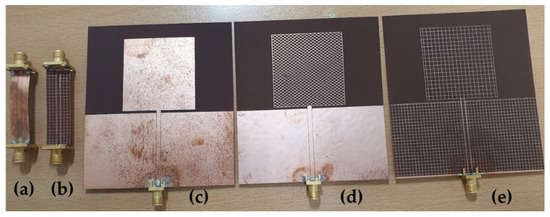
Figure 2.
Manufactured CPWs, antennas; in order from the left of the photo: (a) solid CPW; (b) square-meshed CPW; (c) solid monopole antenna; (d) diamond-meshed monopole antenna with solid feedline; (e) square-meshed monopole antenna with meshed feedline.
3.1. Meshed Feed Line
In Figure 3, the line width and spacing of CPW are designed to have a value of 50 ohms for solid CPW. is 2.263 mm, is 0.12 mm, and the total length of the line is 40 mm. The thickness t of the commonly used copper is 0.018 mm, and the thickness of the dielectric h is 0.2286 mm.
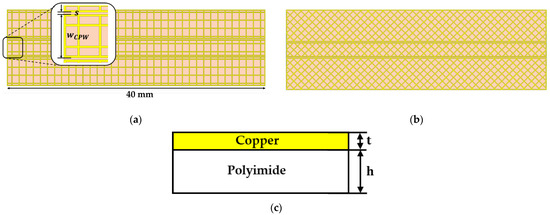
Figure 3.
Meshed CPW configuration: (a) square-meshed CPW; (b) diamond-meshed CPW; (c) side view of meshed line.
An increase in the transparency of the mesh pattern increases the ohmic loss, and an index to compare the effect of this on the transmission line performance is needed. The loss factor was calculated using the scattering parameters from the following Equation (3).
However, since there is an open space in the conductor layer, conductor loss due to the change in sheet resistance is dominant. The loss factor of 40 mm, which is the total length of the simulation model, is affected by the change of the parameters of the mesh pattern. Since the characteristic impedance of CPW changes according to the size of the open space of the mesh, all lines were adjusted to 50 ohms by adjusting . Although meshed CPW has a higher loss factor than solid CPW, it can be compensated for by gaining transparency. However, it is important to design in a line that does not impair the purpose of the existence of transmission line. The loss factor consists of various loss terms.
3.1.1. Square-Meshed Feedline
Figure 4a shows the change in the loss factor when the mesh width was fixed at 0.1 mm and the size of the open space of the rectangular mesh increases from 0.6 to 2 mm within the range of 70 to 90% of the OT. It shows that the loss factor increases proportionally as the size of the open space of the rectangular mesh increases. Figure 4b shows the change of loss factor according to mesh width change. The square mesh was simulated by varying the mesh width from 0.05 to 0.17 mm with 70–90% OT and the open space fixed to 1 mm. Since solid CPW has a loss factor of 0.063, meshed CPW has a higher loss factor due to the effect of higher sheet resistance than the solid CPW generated as an open space for transparency. As the open space increases, the cross-sectional area of the transmission line through which the signal propagates becomes smaller, so more conductor loss is inevitable. In terms of current path, a roundabout current path generated by open space causes more loss as the total path of current increases. A comparison of the simulated and measured results is plotted in Figure 5. A square-meshed CPW with about 83% OT with = 1.1 mm and = 0.1 mm was compared with solid CPW. Although the loss factors are 0.071 and 0.063, respectively, considering the transmission line length of 40 mm, there is no significant difference, so similar S-parameter results were obtained, and it was confirmed that square-meshed line works properly through the measurement results.

Figure 4.
Effect of square mesh on loss factor: (a) length of the open space, ; (b) mesh width, .

Figure 5.
Simulated and measured s-parameter of solid feedline and square-meshed feedline.
3.1.2. Diamond-Meshed Feedline
As in Section 3.1.1, the effect of diamond mesh on transmission line performance by changing the length of open space from 0.3 to 1.4 mm at fixed = 0.1 mm and mesh width from 0.08 to 0.28 mm at fixed and = 1.5 mm within the range of 70–90% transparency was investigated in Figure 6. As shown in Figure 6b, it is shown that the loss factor decreases as the mesh width increases as shown in the square mesh. Unlike square meshes, however, open space in diamond meshes has two parameters. It is the which is parallel to the direction in which the signal is transmitted along the transmission line and the which is perpendicular to the direction. Therefore, when increases, the loss factor increases proportionally, whereas the increase in does not have a large effect on the degradation of transmission line performance in Figure 6a. In particular, when is large ( = 1.2 mm, or 1.4 mm), it is also observed that the increase in improves the transmission line performance. In the case of diamond-meshed line with = 1.0 mm, = 1.3 mm, and = 0.1 mm, which has an OT of 88% higher than that of square-meshed CPW, rather improved s-parameter results can be seen in Figure 7. Comparing the loss factor of the square-meshed line and the diamond-meshed line when the OT is 90%, the square mesh has about 0.078 whereas the diamond mesh has about 0.072. From a transmission line point of view, the diamond mesh is subtly superior, but both lines work well as transmission lines.

Figure 6.
Effect of diamond mesh on loss factor: (a) length of the open space, , ; (b) mesh width, .
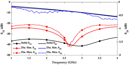
Figure 7.
Simulated and measured s-parameter of solid feedline and diamond-meshed feedline.
3.2. Meshed Antenna
The antenna in Figure 8a will be compared for the solid antenna, square-meshed antenna, and diamond-meshed antenna at 2.4 GHz. Antenna with meshed feedline in Figure 8b will be compared. First, we analyzed the case of applying the mesh only to the antenna. In the case of a square-meshed antenna in Figure 9a, the peak realized gain decreases inversely as the size of the open space increases from 0.8 to 2.8 mm at fixed = 0.14 mm. In Figure 9b, as the mesh width increases from 0.08 to 0.25 mm at fixed = 1.5 mm, the gain of the antenna also increases proportionally. Solid antenna has peak realized gain 3.9 dB, but both have lower values in Figure 9 and Figure 10. In the case of an antenna having the same operating principle, since the effective area of the antenna is proportional to the gain of the antenna, the OT and the gain of the antenna are opposite to each other. Similar to a square-meshed antenna, depending on the transparency, Figure 10a shows a relationship inversely proportional to the peak realized gain when , and vary from 0.6 to 1.8 mm at fixed = 0.14 mm and Figure 10b shows a proportional relationship when varies from 0.1 to 0.42 mm at fixed , and = 1.5 mm. It can be seen that the input impedance of the antenna to which the mesh is applied is hardly unaffected and the meshed antenna and the solid antenna are matched equally well in Figure 11. A simulated and measured 2-d radiation pattern of antennas without meshed feedline was compared in Figure 12. The square-meshed antenna and diamond-meshed antenna were manufactured with the specifications when the transparency was 82%. The solid antenna has a peak realized gain of 3.9 dB, the square-meshed antenna has 3.65 dB, and the diamond-meshed antenna has 3.64 dB. It was confirmed that the effective area of the antenna has a small effect on the gain regardless of the pattern of the meshed antenna, and that all three antennas operate with a similar surface current distribution in Figure 13.
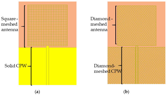
Figure 8.
Meshed antenna: (a) square-meshed antenna without meshed feedline; (b) diamond-meshed antenna with meshed feedline.

Figure 9.
Effect of square mesh on peak realized gain: (a) length of the open space, ; (b) mesh width, .

Figure 10.
Effect of diamond mesh on peak realized gain: (a) length of the open space, , ; (b) mesh width, .
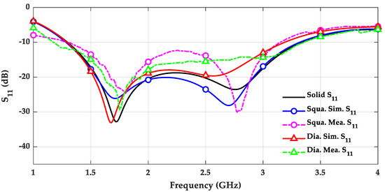
Figure 11.
Simulated and measured reflection coefficients () of the solid antenna, and the meshed antenna.
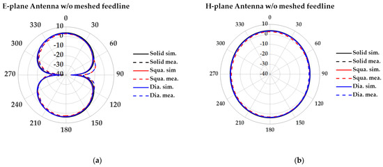
Figure 12.
Simulated and measured 2-d radiation pattern of antennas without meshed feedline: (a) E-plane; (b) H-plane.
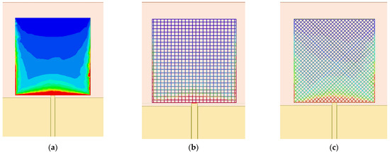
Figure 13.
Surface current distribution of antennas w/o meshed feedline: (a) solid antenna; (b) square meshed antenna; (c) diamond meshed antenna.
Finally, square mesh and diamond mesh were applied to antenna and feedline to have OT 85%. The meshed antenna to which the meshes were applied was compared with the solid antenna in Figure 14. Solid antenna, square-meshed antenna, and diamond-meshed antenna have 3.9 dB, 3.56 dB, and 3.6 dB, respectively, and it has been confirmed that they work well without distortion of the radiation pattern. Even with 85% transparency, the meshed antenna has no problem except for a gain difference of about 0.4 dB. In order to have OT 85%, a square meshed antenna was manufactured with the specifications of = 1.5 mm, and = 0.12 mm, and in the case of a diamond meshed antenna, , and = 1.5 mm, and = 0.18 mm. When two types of mesh are used as micro metal mesh film, it is advantageous in terms of process because diamond mesh can achieve higher transparency with the same mesh width [22]. A comparison of the measured values for Figure 12 and Figure 14 is summarized in Table 1.
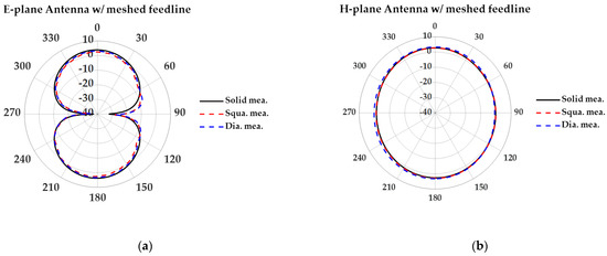
Figure 14.
Measured 2-d radiation pattern of antennas with meshed feedline: (a) E-plane; (b) H-plane.

Table 1.
Comparison of measured antenna performance.
4. Conclusions
In this paper, we studied the effect of design parameters of square mesh and diamond mesh pattern on the performance of transmission line and antenna. In addition, as each design variable changes, the interrelationship between the transparency and performance was investigated. The definition of the transparency of the square mesh is newly applied to the diamond mesh. The diamond mesh showed better performance than the square mesh for transmission lines. The diamond mesh also showed an advantage in terms of process by enabling it to have higher transparency than a square mesh even with a wider line width. The measured results showed that the proposed transparent transmission line and antenna using the diamond and square mesh had similar performance to that of the non-transparent transmission line and antenna. As a result, the possibility of substituting each of the square mesh and diamond mesh in order to avoid haze and moiré in specific parameters was presented.
Author Contributions
Conceptualization, S.Y.; methodology, S.Y.; software, S.Y. and S.L.; validation, S.Y.; formal analysis, S.Y.; investigation, S.Y.; writing—original draft preparation, S.Y., S.L., H.L. and Y.B.P.; writing—review and editing, S.Y., S.L., H.L. and Y.B.P.; visualization, S.Y.; supervision, Y.B.P.; project administration, Y.B.P.; funding acquisition, Y.B.P. All authors have read and agreed to the published version of the manuscript.
Funding
This research was funded by Korea Electric Power Corporation, Grant Number R21XO01-12.
Conflicts of Interest
The authors declare no conflict of interest.
References
- Saberin, J.R.; Furse, C. Challenges with Optically Transparent Patch Antennas. IEEE Antennas Propag. Mag. 2012, 54, 10–16. [Google Scholar] [CrossRef]
- Liu, X.; Jackson, D.R.; Chen, J.; Liu, J.; Fink, P.W.; Lin, G.Y.; Neveu, N. Transparent and nontransparent microstrip antennas on a cubesat: Novel low-profile antennas for cubesats improve mission reliability. IEEE Antennas Propag. Mag. 2017, 59, 59–68. [Google Scholar] [CrossRef]
- Lombardi, J.; Malay, R.; Schaffner, J.; Song, H.J.; Huang, M.-H.; Pollard, S.; Poliks, M.; Talty, T. Copper Transparent Antennas on Flexible Glass by Subtractive and Semi-Additive Fabrication for Automotive Applications. In Proceedings of the 2018 IEEE 68th Electronic Components and Technology Conference (ECTC), San Diego, CA, USA, 29 May–1 June 2018; IEEE: Piscataway, NJ, USA, 2018; pp. 2107–2115. [Google Scholar]
- Kim, I.K.; Wang, H.; Weiss, S.J.; Varadan, V.V. Embedded wideband metaresonator antenna on a high-impedance ground plane for vehicular applications. IEEE Trans. Veh. Tech. 2012, 61, 1665–1672. [Google Scholar] [CrossRef]
- Guillén, C.; Herrero, J. TCO/metal/TCO structures for energy and flexible electronics. Thin Solid Film. 2011, 520, 1–17. [Google Scholar] [CrossRef]
- Simons, R.N.; Lee, R.Q. Feasibility Study of Optically Transparent Microstrip Patch Antenna. In Proceedings of the IEEE Antennas and Propagation Society International Symposium, Montreal, QC, Canada, 13–18 July 1997. [Google Scholar]
- Simons, R.N.; Lee, R.Q. Optically Transparent Microstrip Patch and Slot Antennas. U.S. Patent 5,872,542, 16 February 1999. [Google Scholar]
- Peter, T.; Nilavalan, R. Study on the Performance Deterioration of Flexible UWB Antennas. In Proceedings of the 2009 Loughborough Antennas Propagation Conference (LAPC), Loughborough, UK, 16–17 November 2009. [Google Scholar]
- Serra, C.C.; Medeiros, C.R.; Costa, J.R.; Fernandes, C.A. Mirror-Integrated Transparent Antenna for RFID Application. IEEE Antennas Wirel. Propag. Lett. 2011, 10, 776–779. [Google Scholar] [CrossRef]
- Guan, N.; Furuya, N.; Delaune, D.; Ito, K. Antennas made of transparent conductive films. PIERS Online 2008, 4, 116–120. [Google Scholar]
- Thampy, A.S.; Dhamodharan, S.K. Performance analysis and comparison of ITO-and FTO-based optically transparent terahertz U-shaped patch antennas. Phys. E Low-Dimens. Syst. Nanostruct. 2015, 66, 52–58. [Google Scholar] [CrossRef]
- Colombel, F.; Castel, X.; Himdi, M.; Legeay, G. Ultrathin metal layer, ITO film and ITO/Cu/ITO multilayer towards transparent antenna. Meas. Sci. Technol. 2009, 3, 229–234. [Google Scholar] [CrossRef]
- Hong, S.; Kang, S.H.; Kim, Y.; Jung, C.W. Transparent and flexible antenna for wearable glasses applications. IEEE Trans. Antennas Propag. 2016, 64, 2797–2804. [Google Scholar] [CrossRef]
- Khan, A.; Lee, S.; Jang, T.; Xiong, Z.; Zhang, C.; Tang, J.; Guo, L.J.; Li, W.D. High-performance flexible transparent electrode with an embedded metal mesh fabricated by cost-effective solution process. Small 2016, 12, 3021–3030. [Google Scholar] [CrossRef] [PubMed]
- Hautcoeur, J.; Talbi, L.; Hettak, K. Feasibility study of optically transparent CPW-fed monopole antenna at 60-GHz ISM bands. IEEE Trans. Antennas Propag. 2013, 61, 1651–1657. [Google Scholar] [CrossRef]
- Kang, S.H.; Jung, C.W. Transparent patch antenna using metal mesh. IEEE Trans. Antennas Propag. 2018, 66, 2095–2100. [Google Scholar] [CrossRef]
- Clasen, G.; Langley, R. Meshed patch antennas. IEEE Trans. Antennas Propag. 2004, 52, 1412–1416. [Google Scholar] [CrossRef]
- Hautcoeur, J.; Colombel, F.; Castel, X.; Himdi, M.; Cruz, E.M. Radiofrequency performances of transparent ultra-wideband antennas. Prog. Electromagn. Res. C 2011, 22, 259–271. [Google Scholar] [CrossRef]
- Martin, A.; Castel, X.; Lafond, O.; Himdi, M. Optically transparent frequency-agile antenna for X-band applications. Electron. Lett. 2015, 51, 1231–1233. [Google Scholar] [CrossRef]
- Jilani, S.F.; Abbasi, Q.H.; Alomainy, A. Inkjet-Printed MillimetreWave PET-Based Flexible Antenna for 5G Wireless Applications. In Proceedings of the 2018 IEEE MTT-S International Microwave Workshop Series on 5G Hardware and System Technologies (IMWS-5G), Dublin, Ireland, 30–31 August 2018. [Google Scholar]
- Wawrzyniak, M.; Bras, J.; Denneulin, A.; Vuong, T.P. Influence of Mesh Geometries on the Design of Transparent Antennas at 2.45 GHz. In Proceedings of the 49th European Microwave Conference (EuMC), Paris, France, 2–4 October 2019. [Google Scholar]
- Park, J.; Lee, S.Y.; Kim, J.; Park, D.; Choi, W.; Hong, W. An Optically Invisible Antenna-on-Display Concept for Millimeter-Wave 5G Cellular Devices. IEEE Trans. Antennas Propag. 2019, 67, 2942–2952. [Google Scholar] [CrossRef]
- Ma, H.; Liu, Z.; Heo, S.; Lee, J.; Na, K.; Jin, H.B.; Jung, S.; Park, K.; Kim, J.J.; Bien, F. On-display transparent half-diamond pattern capacitive fingerprint sensor compatible with AMOLED display. IEEE Sens. J. 2016, 16, 8124–8131. [Google Scholar] [CrossRef]
- Lee, S.Y.; Choi, D.; Youn, Y.; Hong, W. Electrical Characterization of Highly Efficient, Optically Transparent Nanometers-Thick Unit Cells for Antenna-on-Display Applications. In Proceedings of the 2018 IEEE MTT-S International Microwave Symposium (IMS), Philadelphia, PA, USA, 10–15 June 2018. [Google Scholar]
- Duy Tung, P.; Jung, C.W. Optically transparent wideband dipole and patch external antennas using metal mesh for UHD TV applications. IEEE Trans. Antennas Propag. 2020, 68, 1907–1917. [Google Scholar] [CrossRef]
- Hautcoeur, J.; Castel, X.; Colombel, F.; Benzerga, R.; Himdi, M.; Legeay, G.; Motta-Cruz, E. Transparency and electrical properties of meshed metal films. Thin Solid Film. 2011, 519, 3851–3858. [Google Scholar] [CrossRef]
Publisher’s Note: MDPI stays neutral with regard to jurisdictional claims in published maps and institutional affiliations. |
© 2021 by the authors. Licensee MDPI, Basel, Switzerland. This article is an open access article distributed under the terms and conditions of the Creative Commons Attribution (CC BY) license (https://creativecommons.org/licenses/by/4.0/).