1. Introduction
Augmented Reality (AR) technology is an information-delivery paradigm that bridges physical and digital objects intuitively and seamlessly. Such synchronization occurs in real time through a user’s engagement with the camera of a mobile device. Key factors that expand its usability are the access to digital content regardless location, the rapid evolution of sensors and the high visual coherence of virtual and real scene. Mobile Augmented Reality (MAR) is a promising support medium for motivating students in learning, recreating in-person event experiences, staff training in healthcare and retail products personalization. Respectively, the Cultural Heritage (CH) sector is undergoing a similar digital transformation. Recent applications for touristic sites [
1,
2], museum exhibitions and art galleries [
3,
4] demonstrate the profound impact of MAR on how data are delivered, perceived and recontextualized. “Changdeok Arirang at Home” is an Android AR application for remotely experiencing a complete navigation at an UNESCO World Heritage site, exploiting 5G mobile edge computing (MEC) for fast and seamless interaction with high-quality AR and Virtual Reality (VR) content [
5]. Combined with adaptive data transmissions MEC technology, reduces the end-to-end latency while multiple users share AR and Mixed Reality (MR) content through the ShareAR application [
6]. Such multiuser collaboration interfaces may be the response for open museums that seek a balance between interactivity and distance through AR technology [
7]. In case of outdoor MAR, the fast transfer of real-world information and the location awareness complement each other. InvercARgill is a MAR urban tour guide that retrieves on the fly location-based information and navigates the user to cultural attractions and heritage activities [
8]. Both applications leverage commercial AR Software Development Kits (SDKs) for pose estimation, tracking and rendering, i.e., ARCore [
9] and Wikitude [
10], respectively. Typically, the overlaid multimedia information comprises text, animation, 3D graphics as well as CAD, wireframe and low-poly models. However, the current advances in photogrammetry, range sensors and fast surface modelling enrich the CH datasets with high-resolution, geometrically accurate and realistic 3D reconstructions. Their large size and complex structure dictate their integration into MAR applications, where visual fidelity is encountered as a crucial factor. The obvious trade-off between visual quality and overall responsiveness is an issue that needs to be tackled even by the commercial AR SDKs.
Regarding the technical requirements of the aforementioned MAR approaches and the trends in media, high-end smartphones and tablets have turned into a necessity. They incorporate depth APIs for depth maps using RGB cameras, 3D Time of Flight (ToF) depth sensors, scanner-less LiDARs, multiple GPU texture resolutions as well as the support required for 5G networks. Moreover, the AR SDKs are running on device models that fulfil certain minimum hardware requirements, such as quad-core CPUs and the existence of Inertial Sensor Units (IMU) sensors. The quality of the camera, the version of the operating system and the architecture also determine the compatibility. While the performance is increasing in terms of motion sensors and computational power, there is still a certain number of users who continue to rely on mobile devices going back almost a decade or long-abandoned versions of operating system. Since they are intended for basic usage, they lack a high-resolution camera sensor, a 3G network as well as the adequate CPU power and storage for intensive applications. Furthermore, their IMU sensors are susceptible to drift over time and their battery drains out in case of sending and receiving geo-coordinates [
11]. They do not qualify support for dedicated SDKs and present outdated features and compatibility issues with well-established applications like Google Maps. The above-noted requirements and characteristics of the latest MAR applications on hardware and software that could be considered as deterrent factors in terms of scaling the AR experience to low-end devices are summarized in
Table 1. Therefore, their users are excluded from any kind of AR-enabled experience, unless more thought goes into promoting the accessibility of this technology.
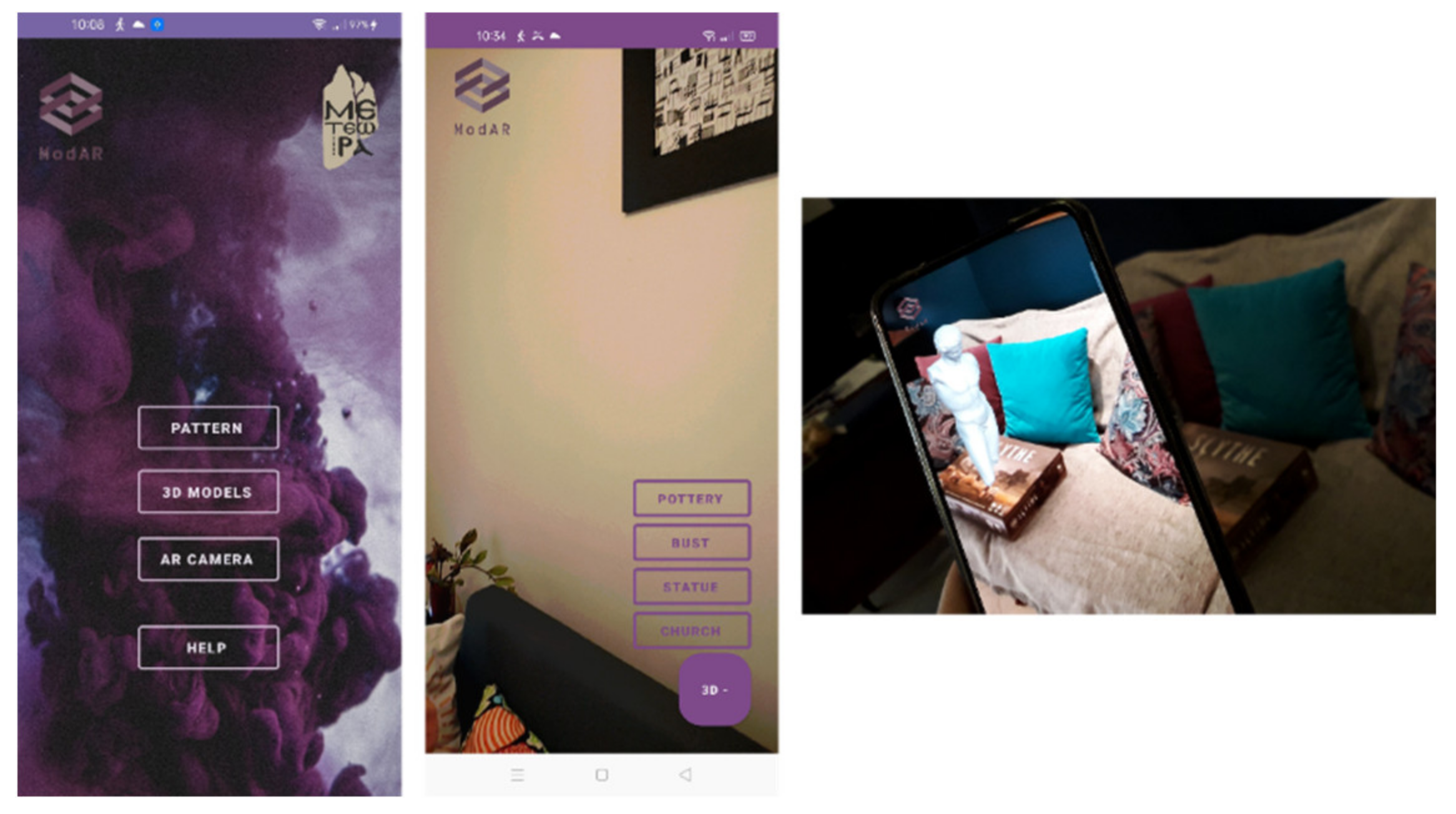
This article presents ModAR, a hybrid MAR Android prototype with cross-vendor portability for planar surface tracking and overlay of 3D textured models. Physical surfaces of the real environment detected in real-time act like an origin for positioning the 3D content. The users can load or capture a pattern image of any planar object and then upload a 3D model of the OBJ format from the internal storage of their device. Alternatively, they can select from a list of the default CH 3D models. The two main processes, i.e., camera pose estimation and 3D rendering, are wrapped into separate modules and performed at the C++ native side with the OpenCV library and at the Java side with the OpenGL 2.0 ES API, respectively. JNI library handles the communication and sharing of objects between computer and graphics work, such as frames and camera pose parameters.
The development targets low-end and mid-range mobile devices which are not certified or cannot enable AR technology, due to device compatibility and operating system constraints. It adapts to low quality camera resolutions, lack of IMU data outputs, network connectivity as well as limited memory and CPU/GPU capabilities. To meet these constraints, two objectives are set: (i) fast and reliable pose estimation exclusively based on feature-based image matching; and (ii) high-performance rendering and qualitative visualization of complex 3D data. For the first objective, two combinations of feature detectors and binary descriptors are evaluated using two different parameterizations. The second objective is accomplished by explicitly managing the time and computations spent on vertex and texture data using vertex data organization, optimized vertex and index buffers, instancing, texture compression and synchronization primitives at run-time.
The main contributions of this article may be summarized as follows:
lightweight AR system for inspection and interaction with 3D objects for both indoors and outdoors;
precise runtime planar surface recognition through feature-based image matching with native C++ code and no dependency on AR SDKs or additional software;
3D OpenGL ES graphics engine dedicated to textured 3D models of OBJ format leveraging workload distribution on multi-core CPUs;
testing and systematic analysis of the performance of well-established feature detectors and binary descriptors for low-end and mid-range devices regarding computational time, CPU usage and robustness to changes of scale, rotation and lighting;
investigation of the optimal combination of vertex data rendering and management, synchronization and texture compression techniques for complex geometries.
The remainder of this article is structured as follows.
Section 2 reviews the state-of-the-art in OpenCV-based MAR applications, feature detectors and binary descriptors along with evaluation studies for MAR applications and 3D volume rendering techniques.
Section 3 presents the main concepts and methodology of the MAR system implemented with pure computer vision algorithms and OpenGL ES graphics API operations. In
Section 4 the system architecture and the ModAR prototype are presented.
Section 5 showcases ModAR functionality through various experiments of image matching, pattern identification and 3D overlays and reports the results of the systematic performance evaluation on compute and rendering procedures. Finally,
Section 6 concludes the findings, strengths and limitations of the presented work and provides insights into future research.
2. Related Work
In recent years, most AR applications rely on AR SDKs like ARCore [
9], WikiTube [
10], EasyAR [
12] and Vuforia [
13]. However, a few applications, mainly developed by the research community, do not have any dependencies on any AR SDK and use methods provided by the OpenCV library for camera pose estimation. For instance, among the OpenCV-based applications, MAR applications have been developed for augmentation of CH sites via multimedia content for Android devices [
14] and via the past situation of a monument for Windows tablet PCs [
15]; a MAR application for Android devices that recognizes pattern images in a campus and overlays 2D information is presented in [
16]; a MAR application that overlays a 3D cube on detected patterns is presented in [
17]. However, the aforementioned Android applications either augment the real scene via 2D information or via elementary 3D shapes, whereas support for 3D textured models is available for Windows-based applications entirely written in C++. In addition, a marker-based MAR framework developed with the use of OpenCV and OpenGL ES is presented in [
18].
Several detectors and descriptors have been developed for extraction of feature points that are invariant to several geometric and radiometric transformations. Detectors usually extract feature points in the so-called “scale space”, to reduce the effect of the change of scale between images during image matching. Additionally, the detected points are usually invariant to translation and rotation transformations between images. Other detectors, which cannot yield subpixel accuracy, identify points of interest based on a comparison of the gray tones of pixels with their neighbors. Finally, detectors that identify points of interest based on supervised machine learning techniques have been developed, taking into account the possibility for each pixel to be a distinct feature. The estimation of the dominant orientation of the extracted feature points, which is required for achieving invariance in rotation transformations, is usually based on the gradients of the pixels in the neighboring area. However, machine learning techniques have also been proposed for dominant orientation estimation. Additionally, a stage of affine shape correction is implemented by some algorithms, in order to ensure invariance in viewpoint transformations between images, taking into account the fact that for small image windows, perspective image changes may be approximated by an affine transformation. Feature point description follows. The descriptors may be divided into two main categories: floating point descriptors and binary ones. Floating point descriptors use gradient estimation in a feature support window (which usually depends on the scale of each detected point and defines its neighborhood). They are characterized by greater distinctiveness compared to binary descriptors, but they are computationally demanding. Binary descriptors are usually computed based on comparison of gray values within the feature support window and save the comparison results in the form of binary numbers. They are characterized by better speed performance and lower memory requirements and are thus more suitable for real-time applications. Machine learning descriptors have also been developed in recent years, being calculated using a function with trainable parameters. Moreover, recent research on machine learning techniques, including neural embedding matching [
19], multiple kernel active learning [
20] and deeply supervised attention metric-based network [
21], may be explored for effective feature extraction and matching. An extensive evaluation of image feature descriptors for vision-based marker-less AR applications was implemented in [
22]. However, the testing was performed using a PC-based AR application and was not optimized for MAR. Additionally, an interesting accuracy measurement of state-of-the-art binary descriptors for MAR applications was performed in [
23] using an Android device. However, this study does not focus on low-end devices, which is the scope of our work.
Within this article, several combinations of detectors and binary descriptors, optimized for better performance in real-time applications, are dealt with, within the process of feature-based image matching. FAST (features from accelerated segment test) is a detector [
24] characterized by speed in detecting corners, being faster than other commonly used point detection operators (e.g., Harris, Difference-of-Gaussian, etc.). It can also be combined with machine learning techniques to achieve even better performance in computational time. A variant of FAST is the AGAST (adaptive and generic accelerated segment test) operator [
25], which shows improved performance through combining specialized decision trees. As far as feature description is concerned, taking into account the fact that binary descriptors are faster than floating point ones, only binary descriptors were selected to be tested in the developed application. BRIEF (binary robust independent elementary features) [
26] is a binary descriptor that relies on random differences of pixels selected around each feature point, after the image has been blurred. The description of feature points through BRIEF is independent of changes in contrast and brightness. However, it is sensitive to rotation transformations. The basic principle of the binary descriptor ORB (oriented FAST and rotated BRIEF) [
27] is the same as that of BRIEF, but the points described by ORB are invariant to rotation transformations, thanks to the orientation of BRIEF descriptor based on the angle calculated during the process of feature extraction via a variation of the FAST operator, in which an orientation assignment mechanism has been added by the authors of ORB. However, both BRIEF and ORB are sensitive to scale transformations. The BRISK (binary robust invariant scalable keypoints) descriptor [
28] uses scale information of the extracted feature points before their description, achieving also independence of scale transformations, in addition to independence of rotation transformations. BRISK determines the orientation of feature points detected in scale space and makes comparisons of the values of tones of point pairs that are evenly extracted in concentric circles around each feature point. The ORB descriptor uses the FAST detector along with an orientation assignment mechanism; BRISK uses the AGAST operator.
3D rendering on the mobile tile GPU architecture is an active area of research with significant number of methods, algorithms and implementations. The rest of the literature review’s emphasis is on AR-dedicated and general 3D engines for the Android operating system as well as building blocks and techniques of the OpenGL ES graphics pipeline that are commonly used for performance optimizations. Graphics engines and frameworks for Android MAR applications are mainly built under the license of commercial and free SDKs mentioned above, such as Sceneform [
29] for ARCore and the SDK-dependent rendering engines of WikiTube, EasyAR and Vuforia on native SDK. Among these, Sceneform by Google integrates an open-source SDK that uses physically based rendering (PBR) to build AR applications without requiring OpenGL ES.
Regarding 3D loaders of general use with low-level bindings on OpenGL, Filament [
30] is a lightweight cross-platform PRB engine for glTF files format that adapts to low and medium performance GPUs. 3D Model Viewer [
31] is an Android application launched at the Google Play Store, for loading and visualizing 3D models of OBJ, STL (STereoLithography) and DAE (Collada) format. It further integrates features like collision detection, 3D stereoscopic view and raycasting. The Rajawali 3D framework [
32] enables importing and displaying various types of 3D models including OBJ, 3DS and FBX, in the context of an optimized rendering scheme that supports object serialization and compression. It has been coupled with Vuforia SDK as the base file parsing and renderer for MAR [
33] as well as with Jaguar client and ARCore SDK for low-latency MAR with object tracking to the edge cloud [
34]. A seminal contribution in the field is the open-source LWJGL Java Game library [
35] with direct and high-performance access to native APIs and bindings to OpenGL ES. Besides gamification, it has been designed as a low-level interface for graphics acceleration, addressing any type of visualization need.
In the context of the presented work, no ready-to-use rendering frameworks, engines or file parsers were utilized. Instead, a graphics engine for high-volume 3D meshes and low-end hardware was developed from scratch. Recent studies explore performance acceleration for such large vertex data exploiting the newly introduced objects of shader storage buffer objects (SSBO) that optimize the existing Uniform Buffer Objects (UBO) and texture buffer objects (TBO) for random access data in shaders. These objects can be part of any direct or indirect rendering function of the graphics API, including: Multi-Draw and Multi-View rendering [
36], indirect rendering that issues the drawing commands stored at a buffer object of GPU and conditional rendering that schedules rendering commands depending on visibility checks of an occlusion query [
37]. In the proposed rendering scheme, only the techniques compatible with OpenGL ES version 2.0 and associated with the technical requirements being set are taken into consideration. This version still targets the widest range of devices in the market and exposes programmable shaders that are really useful for explicit graphics acceleration. However, evaluation testing on multiple 3D models records bottlenecks at the vertex and fragment processing of the graphics pipeline. A performance amelioration strategy is the configuration of the number ration of the shading processing units which substantially balances the load [
38]. Occlusion or visibility culling methods drastically reduce redundant fragment processing computations by avoiding the processing of occluded surfaces of the 3D model, but are not suitable for low-power devices [
39,
40].
Various practices for CPU limited cases and increased draw calls count have been developed for performance acceleration. Instancing is tailored to complex meshes with thousands of vertices and entails rendering of multiple identical meshes in a single draw call. It has been applied to Building Information Models (BIMs) along with occlusion culling [
41], to 3D CAD models in dynamic scenes [
42] or during cloud rendering [
43] and to a k-d tree construction algorithm for massive sets of objects [
44]. Regarding texture management, a series of pre-processing algorithms, including mesh partitioning, parameterization and packing along with high-quality texture map generation, achieves a texture size that maintains the original resolution [
45]. A novel texture map representation and adaptive sampling strategy that stores the appearance relative information directly on 3D meshes has recently been proposed [
46]. However, at the current development phase, the large-sized meshes cannot be rendered from their compressed mesh texture. A contribution worth mentioning on texture atlas compression preserves the geometric attributes of the 3D model with random access decoding and view-dependent transmission [
47]. Finally, some fixed functions of OpenGL and principal methods for performance boost and visual quality include frustrum culling, per-vertex operations, shader reduction and texture filtering. A minor degradation of visual quality using a combination of simple techniques compensated for an average of 19% performance improvement in [
48]. The problem of optimizations on single-threaded applications for low-end hardware has not recently been tackled, as developers are taking high-end smartphones ownership into granted. Building MAR is still an arduous task. Designing immersive AR experiences with a low-quality camera, and for low functional and digital literacy users is even more challenging, but it really achieves AR democratization.
3. Methodology
Within this section, the pattern-based MAR methodology followed by the ModAR is presented. The pattern object is assumed to be a planar rectangle surface. A nadir image of the pattern object, herein after referred to as pattern image, is required for augmentation of the real-world frames via a 3D model, also required by the proposed method, along with the camera internal parameters.
The origin of the world coordinate system is assumed to be located at the center of the pattern object. The
X and
Y axes lie on the pattern object plane, while the
Z axis is perpendicular to it, pointing to the camera. The
X and
Y coordinates of the four corners of the pattern object in the world coordinate system are computed using the normalized width (
W) and height (
H) of the pattern image, according to Equation (1):
where
cols and
rows are the number of columns and rows of the pattern image, respectively. Thus, the
X and
Y coordinates of the four corners of the pattern object range from −1 to 1. Their Z coordinate is set to zero (
Figure 1).
3.1. Feature Extraction and Image Matching
Feature points are extracted once in the pattern image (offline) and in every camera frame during runtime. The following combinations of detectors and binary descriptors are dealt with, within the process of image matching in ModAR: (i) the oriented FAST detector (i.e., FAST with an orientation assignment mechanism developed by the authors of ORB) combined with the ORB descriptor; and (ii) the AGAST detector combined with the BRISK descriptor. ORB uses the oriented FAST detector, while the BRISK descriptor uses the AGAST operator. These combinations of detectors—descriptors have been proposed by the authors of these algorithms, i.e., [
27,
28], respectively.
The stage of finding correspondences between the extracted feature points is performed by matching their descriptors using a similarity measure. Whereas in case of floating-point descriptors, this measure is usually the Euclidean distance between the descriptors, in the case of binary descriptors, the Hamming distance is used. It is calculated as the number of positions at which the binary values of the descriptor vectors are different. However, the minimization of the Hamming distance does not suffice, and thus it is combined with other techniques in order to reject incorrect correspondences. In our work, a cross-check test is implemented. According to this test, the descriptor of each feature in the pattern image is compared with the descriptor of every feature in the real-world frame and some candidate correspondences are returned. These are additionally checked through reverse comparison. Thus, two feature points,
i and
j, are matched if the nearest neighbor of the descriptor of point
i in the pattern image is the descriptor of point
j in the camera frame and reversely if the nearest neighbor of the descriptor of point
j in the camera frame is the descriptor of point
i in the pattern image. However, after cross testing, many outliers still remain. Therefore, a maximum accepted distance is defined as a threshold (equal to 1/3 of the descriptor length in bits) and the correspondences are rejected if the Hamming distance between the descriptors of the matched feature points is above this threshold. In this way, a significant number of outliers is removed, although a few incorrect matches are not detected. These are rejected using the RANSAC (random sample consensus) algorithm [
49]. The latter is applied if at least 8 matches are detected. Otherwise, the real-world scene is not augmented, as it is considered that the pattern cannot be recognized in the frame. RANSAC calculates the parameters of a mathematical model using a data set, which may contain many errors, relying on the use of minimum data. In the case of ModAR, the dataset consists of the remaining correspondences and the model is the geometric relation between the pattern image and the image of the planar pattern object in the camera frame, i.e., a 2D projective transformation (homography). The correspondences that verify the homography computed by RANSAC constitute the inliers.
3.2. Pattern Recognition and Camera Pose Estimation
The homography matrix is linearly calculated by RANSAC, with the use of the best combination of four matches, without using all the inliers detected by the algorithm. Thus, the initial homography estimation, obtained by RANSAC, is refined using all the inliers, through nonlinear optimization using the Levenberg–Marquardt algorithm [
50]. If a minimum number of 8 inliers is detected by RANSAC, pattern recognition takes place and the 3D model is rendered, superimposed on the camera frame. Otherwise, the scene is not augmented, as the pattern object cannot be recognized in the frame. The recognition of the pattern object in the camera frame takes place through calculation of the pixel coordinates of its four corners, using the estimated homography transformation and the pixel coordinates of the four corners of the pattern image.
The estimation of the camera 6-degrees-of-freedom (6-DOF) pose for every camera frame is accomplished using the camera interior orientation parameters, the pixel coordinates of the corners of the planar pattern object in the camera frame and their corresponding coordinates in the world coordinate system. The results of the aforementioned computation are the translation of the origin of the world coordinate system into the projection center, which is the origin of the 3D Cartesian camera system, and the rotation of the world coordinate system into the camera system. The mathematical model used is the projection transformation, expressed by Equation (2):
where
x,
y are the image coordinates of a point in the camera frame corrected by the effects of distortion;
X,
Y,
Z are its real-world coordinates;
c is the camera constant;
x0,
y0 are the coordinates of the principal point;
rij are the elements of the rotation matrix
R;
ti are the elements of the translation vector
t; and
λ is a scale factor.
The elements of the joint rotation-translation matrix are computed linearly according to Equation (3), after undistortion of the image coordinates of the four corners of the pattern in the camera frame and computation of the 2D homography
H that relates the
X,
Y world coordinates of the pattern with the corresponding undistorted image coordinates:
where
hij are the elements of the 3 × 3 homography matrix.
Due to noise in data, the computed rotation matrix
may not satisfy the properties of a rotation matrix. Thus, it is “coerced” to satisfy the orthogonality condition
by calculating its singular value decomposition (SVD), thus factoring it into two orthonormal matrices
U and
V and a middle matrix
W with the singular values of
R in its diagonal, as shown in Equation (4):
The best approximating matrix is then given by Equation (5) [
51]:
Then, the rotation matrix is transformed to a 3D rotation vector, using the Rodrigues rotation formula [
52]. This vector indicates the direction of the rotation axis with its magnitude being equal to the magnitude of the rotation. This axis-angle representation is more compact than a rotation matrix, so it is more suitable for optimization procedures. Subsequently, the 6-DOF camera pose is optimized via the Levenberg–Marquardt algorithm and the rotation vector is converted back into a 3 × 3 rotation matrix using the Rodrigues formula. The result of this process is the joint rotation–translation matrix [
R|
t] for each frame.
3.3. 3D Rendering
A 3D geometry encoded in the OBJ format consists of the object file (.obj) and the material file (.mtl). Wavefront OBJ format properly stores the vertices, faces, normal textures and texture coordinates. The basic rendering CPU-bound technique is described as follows. On initialization, the 3D renderer sends the data to a buffer of memory called Vertex Buffer Object (VBO) which can be accessed by GPU. The OpenGL ES app reads the attributes of the vertex data and maps them to the vertex shader as attribute values. The vertex shader expects the position of the vertex to be defined in clip space, relative to the camera view. Thus, a sequence of transformations, namely Model View Projection (MVP), is applied to the vertices at each frame and is updated during drawing calls. The model matrix
MMODEL transforms them from the object coordinate system to their
υ’ position in the world. The view matrix
MVIEW sets the translation from the world coordinates to the, not yet projected, camera coordinates. The separation of the two matrices is rather conceptual; we can refer to a single matrix called
MMODELVIEW. At this point, the coordinate system is assumed to be centered at the origin, so the
MMODELVIEW matrix actually contains the transformation that places the 3D model in front of the camera. These coordinates are normalized by applying a perspective projection that is mathematically represented by the projection matrix
MPROJ. Therefore, the transformation of the 3D coordinates in 2D screen coordinates of the homogeneous space is expressed by Equation (6):
Then, at each frame, the application sets the vertex and index buffer iterating over the different materials and binds the corresponding one to the GPU. The fragment shader calculates the final color of on-screen pixels, using the interpolated values of UV texturing. It parses the UV texture coordinates of the texture image of the corresponding 3D model in order to determine how the 3D surface should be painted. These images are called UV texture maps and consume the largest amount of the available memory; thus, optimizations on texture size, format and usage are inevitable for low-end devices. Firstly, the files are compressed offline with ETC-pack (ETC1 type) and uploaded with GL_RGB8 image format in order to be stored in RGBA order. Then, sub-texturing is applied with the format PVRTC, and at a certain ratio, referred to as the level of detail of the sample image. That value depends on the size of the base mipmap level, i.e., level 0, that defines the effective size of each texture image. When parts of the textured mesh are updated from the image data, it is common to copy the entire image. To prevent high texture memory consumption, an alternative strategy is followed: the whole width of the image is copied, while vertically, only the part that has changed is copied. Multiple framebuffers are finally used for the offscreen rendering. During the rendering loop, performance is impacted by high faces count. Moreover, CH models are georeferenced, packed with coordinates of large values that may exceed the standard floating-point precision in depth buffer as well as in texture mapping. In order to efficiently process vertices, a method based on vertex data organization, frustrum culling and instancing is applied.
The OBJ files are merged into the same buffer objects with the same vertex format using the same uniform values of a single shader program. To render individual meshes with a single draw call, offsets are set in order to pick and choose between them. The model space is rearranged so that all attribute positions are packed in a range of [−1, 1] around the origin. After calculating the minimum/maximum values of their 3D geometric coordinates among all positions, the center point is subtracted from all vertex positions with the corresponding scaling. This center point offset and scale is applied at MMODELVIEW. Normals are also converted into normalized integers stored in vertex arrays. Filling vertex buffers with half float coordinates improves the overall rendering performance. Moreover, indexed draw calls of a small index type are used while the vertices of the meshes are drawn. This decreases the amount of index data that the GPU needs to access for each draw call, at the expense of slightly more complicated application logic. To reduce the scene range and the amount of data transmission between CPU and GPU, chunks of the models that are not temporarily displayed are excluded using frustrum culling. Only the vertices that are visible, even partially, are sent to the GPU. This is achieved by setting the positive values of near and far distances into the orthographic projection matrix.
During instancing, the same mesh is being drawn multiple times. This process involves storing
n matrices in a uniform buffer and calling them once to draw
n copies. The matrix needed for each instance is fetched from the uniform buffer using an indexed unique value that has to be declared in the shader. The geometry-instancing technique renders all vertices and triangles of a scene through the shader using one call [
53]. Unique attributes, such as transformation matrices, can be provided for every single occurrence of the mesh but repetition is a priori. In our case, the AR session comprises one 3D model that is loaded once the camera module detects the pattern and image matching occurs. When tracking is lost between 2 consecutive frames, the 3D model is drawn again at the specific pose. Destroying and re-rendering or creating a copy of the 3D model’s data to a new object are expensive procedures for low-end GPUs. Therefore, a batch system that renders all the active models based on geometry-instancing has been developed. The vertices of the meshes are already stored into a vertex buffer and the transformation matrices to a uniform buffer. Then, an instancing stream that contains the index of the matrix within the uniform buffer is created. The index should be used by the vertex data when rendering and this approach leads to an identical instancing setup and uniform buffer data. Besides instancing copies of a single mesh, this technique achieves fast drawing of multiple non-identical meshes.
The aforementioned methods and proposed strategies are implemented in the context of an independent 3D graphics engine that configures a complete rendering pipeline for OBJ 3D models. They reside as activities or functions and constitute building blocks for the rendering and visualization of the AR scene of ModAR. In addition, they can be built and used standalone for any other graphics application based on OpenGL ES 2.0.
3.4. Augmented Reality
The AR functionality entails the registration, i.e., the spatial alignment of the real and virtual objects. For marker-less AR based on pattern detection, the 3D model is expected to be placed in the center of the pattern, with the
Z axis in the direction of the camera. The coordinates of the vertices of the 3D model in its local coordinate system are transformed to the world coordinate system by being normalized in the range [−1, 1]. They may also be multiplied with a user-defined scale factor, in order to give the 3D model the intended size relatively to the pattern object. The data needed to achieve the registration and the visualization of the 3D overlay are: (i) the parameters of the camera exterior orientation estimation, (ii) the camera calibration matrix, (iii) the pattern image as well as (iv) the draw and load functions of the 3D engine. In our implementation, the camera pose parameters constitute a shared resource that should be accessed by the compute and rendering module. For the synchronization of access and the execution of the various calls, semaphores are exploited. They are memory variables in the form of integers, indispensable for multi-tasking programming. The 3D model’s pose tracking must wait until the semaphore’s value is positive, then changes the semaphore’s value by subtracting one from it. When it is finished, the thread performs feature extraction and pattern detection, which change the semaphore’s value by adding one to it. However, whenever any process waits, it continues checking for the semaphore value and waste CPU cycle. To prevent busy waiting, a system
call block is exploited and a queue is created to contain the functions that got blocked while performing down operation. The process which is currently being executed is added to the queue, and when completed, it calls the signal function and the previous process in the queue is resumed. Thus, synchronization prevents extra memory loads and multiple waisted memory cycles. The elements of the estimated joint rotation-translation matrix [
R|
t] of the camera pose object are converted to float values and define the current model matrix
MMODEL. Then, the known intrinsic camera matrix
MCAM is translated from a perspective projection into an OpenGL projection matrix
MProj. The view frustrum specifies the perspective projection
MPersp that is then converted into normalized device coordinates
NDC in the range [−1, 1] in 3 axes, according to Equation (7), which describes their inverse correlation.
The clipping points between the “near” and “far” planes of the view frustrum cut it perpendicularly to the viewing direction. The distance between them affects the precision of depth-buffering. If the “near” value is reduced, the pixel of vertices near the “far” plane might be wrongly rendered. Instead of “near” and “far” values, the depth limits are defined with the field of view (FOV) and the aspect ratio. The AR scene rendering further involves construction of the vertex and fragment shaders, parsing of the 3D OBJ file, its material properties and its sub-texture image as well as the lighting and camera settings.
5. Experimental Results and Discussion
In this section, the results of various usage scenarios on pattern identification and scene augmentation along with an extensive evaluation testing during the execution of the ModAR prototype on low-specification devices are presented. The input testing dataset of pattern images and 3D models is described before proceeding to the main evaluation phase. Then, the results obtained by profiling CPU usage, timing, frame rate and memory allocation separately on the native side during pattern recognition and on the Java side for the 3D graphics engine are reported and discussed.
5.1. Testing Dataset and Experimental Setup
The overall objective is to understand the impact of the hardware specifications on the performance attained by both the computational and rendering operations of ModAR. Moreover, the examination of the effectiveness of the developed techniques and strategies as well as the interpretation of the testing results lead to guidelines and suggestions. The testbed comprises one old low-end and one affordable mid-range Android mobile device. The minimum target version of ModAR is Android API level 19, a.k.a. Android 4.4 KitKat, released on 31 October 2013 (
Table 2) and the OpenGL ES version is 2.0. The six different pattern images and four 3D models that come with the ModAR prototype (
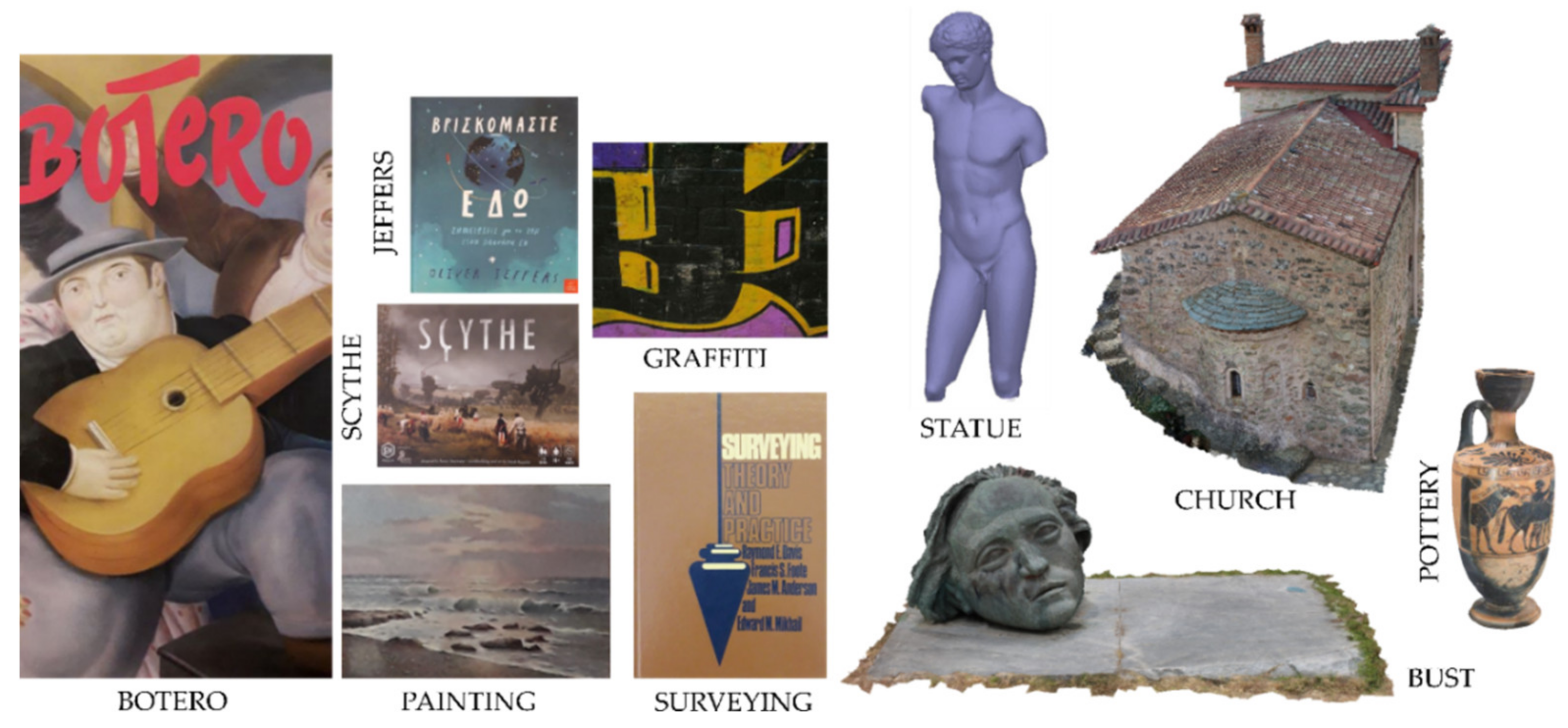
Figure 4) were used in the experiments. The pattern image hereinafter referred to as “BOTERO” is part of a book cover; the pattern image “SCYTHE” is the planar front surface of the box of a board game; the pattern images “SURVEYING” and “JEFFERS” are book covers; “PAINTING” is a wall painting inside a frame; and “GRAFFITI” is an outdoor wall mural. The size of the pattern images used in the experiments is within the range 0.07–0.25 MP (see
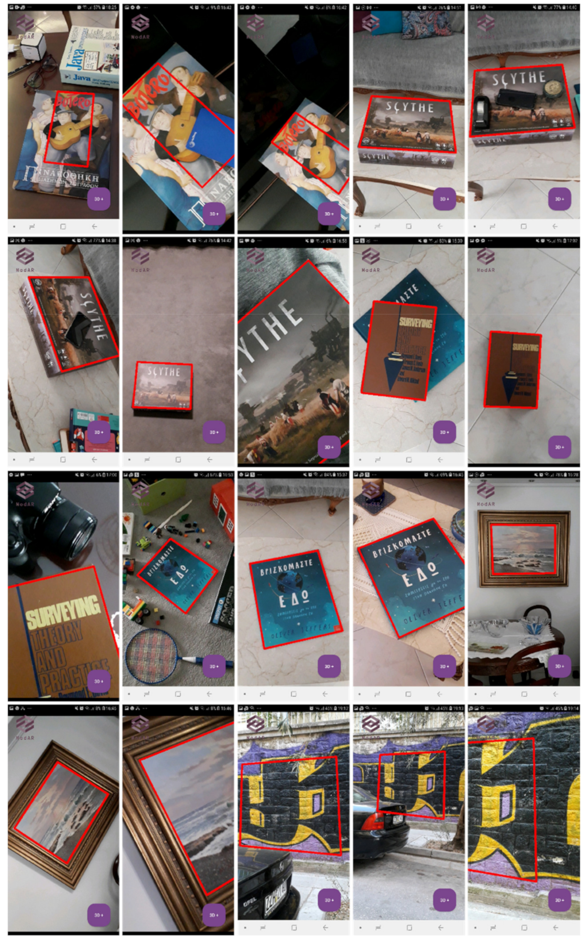
Table 3 for the exact dimensions), while the size of the camera frames in the test devices is 0.92 MP for the low-end device (720 × 1280 pixels) and 2.07 MP for the mid-range device (1080 × 1920 pixels), both corresponding to a frame rate of 30 FPS. The textured Wavefront OBJ models are of multiple scales and heterogeneous sources, like image-based photogrammetry and terrestrial laser scanning. Each model differs in size and complexity, thus “POTTERY” and “BUST” are denoted as small models, “STATUE” as of regular size and “CHURCH” as large model. “STATUE” is the only one with vertex color and no texture.
5.2. Image Matching and Pattern Recognition
The BRISK and ORB feature point descriptors along with the corresponding detectors proposed by the authors of these descriptors were evaluated in the ModAR prototype. Specifically, the AGAST detector combined with the BRISK descriptor and the FAST detector along with an orientation assignment mechanism combined with the ORB descriptor were used. Two different parameterizations were evaluated for each combination of detector–descriptor, as summarized in
Table 4 and
Table 5.
The difference in the experiments performed by the AGAST and BRIEF operators lies in the number of octaves. Specifically, 3 octaves were evaluated in the experiment “AGAST-BRISK-3”, while 2 octaves were used in the experiment “AGAST-BRISK-2”. The difference in the experiments performed by the oriented FAST detector and ORB descriptor lies in the maximum number of feature points per image, i.e., 2000 features for the experiment “FAST-ORB-2000” and 500 features for the experiment “FAST-ORB-500”.
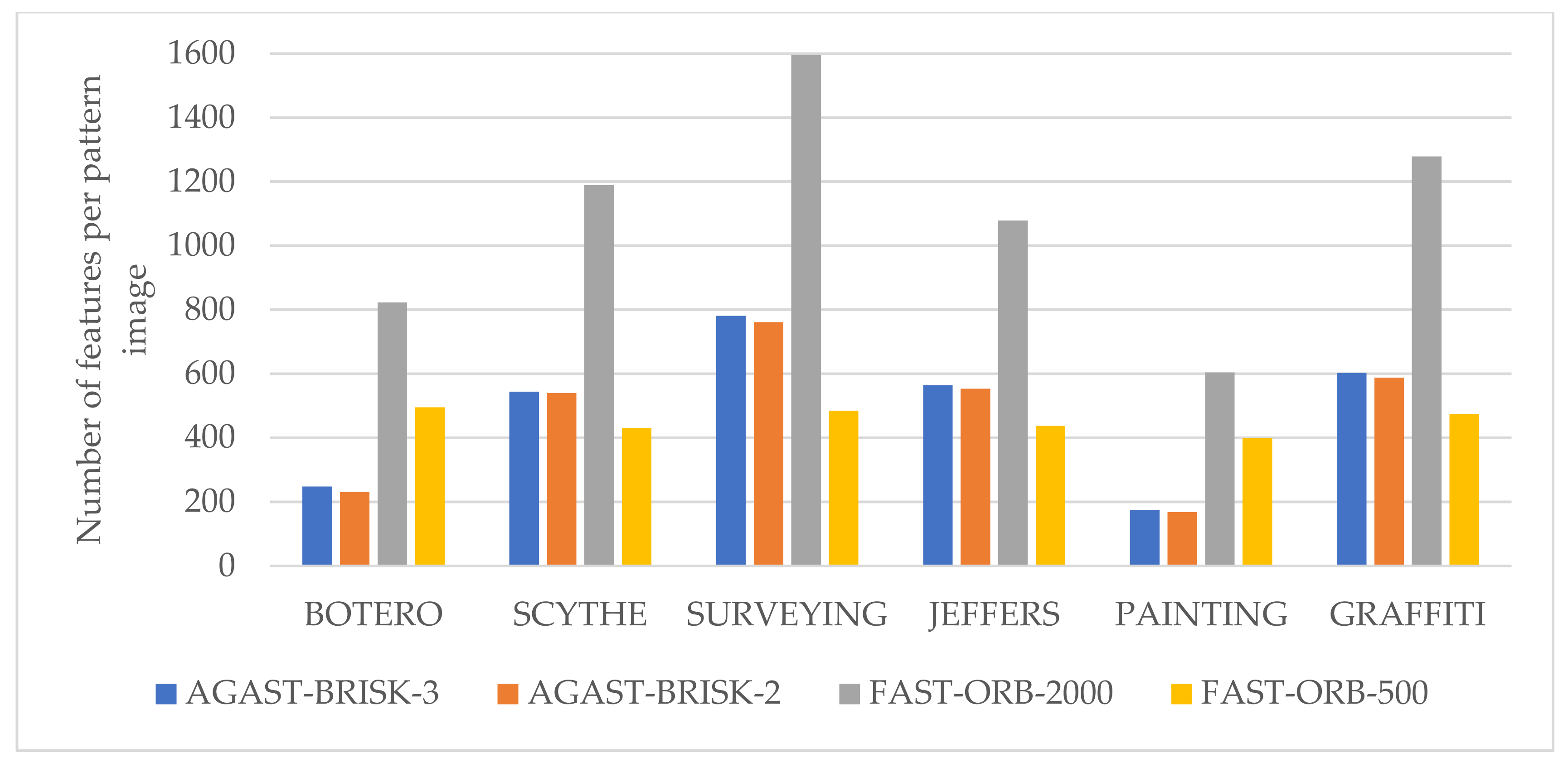
The number of feature points extracted in each pattern image for every experiment performed by the ModAR prototype is outlined in
Table 4. The experiment FAST-ORB-2000 yields the greatest number of feature points in each pattern image, which significantly differs based on the pattern image. The small dimensions of each pattern image along with the lack of corners in some of them resulted in much less features than the maximum threshold of 2000 in this experiment. The experiment FAST-ORB-500 yields approximately similar numbers of feature points in each pattern image (lying within the range of 400–500 features), because of the threshold of 500 features per image. The experiments AGAST-BRISK-3 and AGAST-BRISK-2 yield approximately the same number of features in the tests performed with the same pattern images, as their only difference is the number of octaves used in scale-space. The smallest number of feature points per pattern image is observed either by the experiment AGAST-BRISK-2 or by the experiment FAST-ORB-500. While the number of feature points extracted by the latter lies near the upper threshold of features set by this experiment, the number of features extracted by the AGAST detector greatly depends on the content of the pattern images (i.e., the detected corners) and differs based on it.
Figure 6 illustrates clustered bar charts with the number of feature points for each pattern image, extracted by the tested detectors with different parameterization.
Whereas the greatest number of feature points in the small-sized pattern images is observed for the FAST-ORB-2000 experiment, the greatest number of feature points per camera frame along with the greatest number of matches is observed by the AGAST-BRISK-3 and AGAST-BRISK-2 experiments, as outlined in
Table 6. This is explained by the lack of any upper threshold for the number of feature points in the use of the AGAST detector along with the higher resolution of the camera frames compared to the resolution of the pattern images. Furthermore, the fact that the number of features along with the number of outliers significantly differ for every camera frame is due to the quite different content of each one, which depends on the depicted scene.
Taking into account the fact that a MAR application should act in real-time, the image matching process between the pattern image and consecutive frames should be accomplished in the shortest time possible. Hence, a very important measurement of this research is the computational time of the image matching process, which is the most resource-demanding task of the computer vision workflow.
Table 7 shows the average computational time required by the four basic steps of the image matching and outlier removal process (i.e., feature detection; feature description; main process of image matching; and homography estimation for geometric verification of matches) for each experiment performed via ModAR using the low-end device.
Table 8 shows the corresponding results for the mid-range device. These results were derived using 50 camera frames for each pattern image used in the experiments (in total 300 frames); the metrics have been collected using Android profiler.
As far as the computational time of image matching is concerned, the results showed that the oriented FAST detector used by ORB along with the ORB descriptor required the shortest time to complete both the detection and description processes. On the other hand, the AGAST detector combined with the BRISK descriptor were significantly slower in terms of computational time required for both the detection and description processes, thus being unsuitable for real-time AR applications for both low-end and mid-range devices. Approximately the same time was required for feature detection by AGAST and feature description by BRISK. However, ORB feature description required almost 3 times more time to be accomplished compared with feature detection by oriented FAST.
The AGAST-BRISK-3 experiment was the most time consuming one. The AGAST-BRISK-2 experiment was a little faster. However, both experiments were proved to be unsuitable for the ModAR prototype. The FAST-ORB-500 experiment was accomplished in the shortest time, as it required in average 0.309 s for the low-end device and 0.250 s for the mid-range device. Additionally, the FAST-ORB-2000 experiment proved to be suitable for AR augmentation, as it was accomplished in average in 0.434 s for the low-end device and 0.356 s for the mid-range device. Thus, only the combination of the oriented FAST detector and ORB descriptor were further evaluated in ModAR. They achieve about 90% reduction in the computational time of image matching compared to the corresponding time required by the AGAST detector and BRISK descriptor. The rest tasks that complete the computer vision workflow (mainly the reading of the extracted feature points of the pattern image and their descriptors in each frame, along with the basic steps of pattern recognition and camera pose estimation) were completed in less than 0.250 s for all experiments. The total computational time required by the four basic steps of image matching for each experiment performed via ModAR is illustrated in the form of clustered bar charts in
Figure 7.
Similar results were achieved regarding CPU usage. Specifically, the amount of CPU time that the application process uses for each method as a percentage of the total available CPU time of the device concerning the computer vision workflow is shown in
Table 6, for the low-end device and in
Table 7, for the mid-range device. The feature detection and description tasks implemented by the time-consuming experiments AGAST-BRISK-3 and AGAST-BRISK-2 correspond to approximately 95% of CPU usage out of the total CPU usage of the computer vision workflow, whereas the corresponding CPU usage percentage for feature detection and description by oriented FAST and ORB reaches approximately 50%. The detection of correspondences along with homography estimation are neither time-consuming tasks nor CPU-demanding, as shown in
Table 6 and
Table 7.
As far as the pattern recognition results are concerned, the correspondences detected by the ModAR prototype generally lead to successful pattern object recognition in all the aforementioned experiments. Both AGAST-BRISK and FAST-ORB yield successful pattern recognition results regardless of the rotation of the pattern object. Whereas the use of the AGAST detector in combination with the BRISK descriptor yields better results in cases of strong change of scale between the pattern object and its appearance in the camera frame, the computational time required by AGAST feature detection and BRISK description is prohibitive for AR applications, as discussed in the previous paragraphs.
For 100 camera frames for each pattern image (600 frames in total), the recognition accuracy, i.e., the ratio between the number of successful pattern recognitions in the camera frames over the total number of frames, is 100% for all combinations (AGAST-BRSIK-3, AGAST-BRISK-2, FAST-ORB-2000 and FAST-ORB-500) for camera frames where the resolution of the pattern in the frame is 0.9 to 4 times the resolution of the pattern image, regardless of any in-plane rotation. The recognition accuracy for resolution of the pattern in the frame from 0.4 to 0.9 times the resolution of the pattern image drops to 93% for FAST-ORB-2000 and 88% for FAST-ORB-500. The recognition accuracy for the combination AGAST-BRSIK-3 and AGAST-BRISK-2 for resolution of the pattern in the frame from 0.4 to 0.9 times the resolution of the pattern image is better (97% and 95% respectively); however, the loss in speed is really significant and these combinations are discarded for being used in ModAR. The FAST-ORB-2000 parameterization achieved more stable results, compared to FAST-ORB-500, as proved by the aforementioned recognition accuracy. Despite the slightly better performance in terms of computational time and CPU usage of the latter, the FAST-ORB-2000 yields the overall best performance in terms of stability of pattern recognition and good performance in time. Hence, this is the parameterization finally used by ModAR (and thus adopted by the screenshots from ModAR illustrating the pattern recognition and AR augmentation processes in
Figure 4).
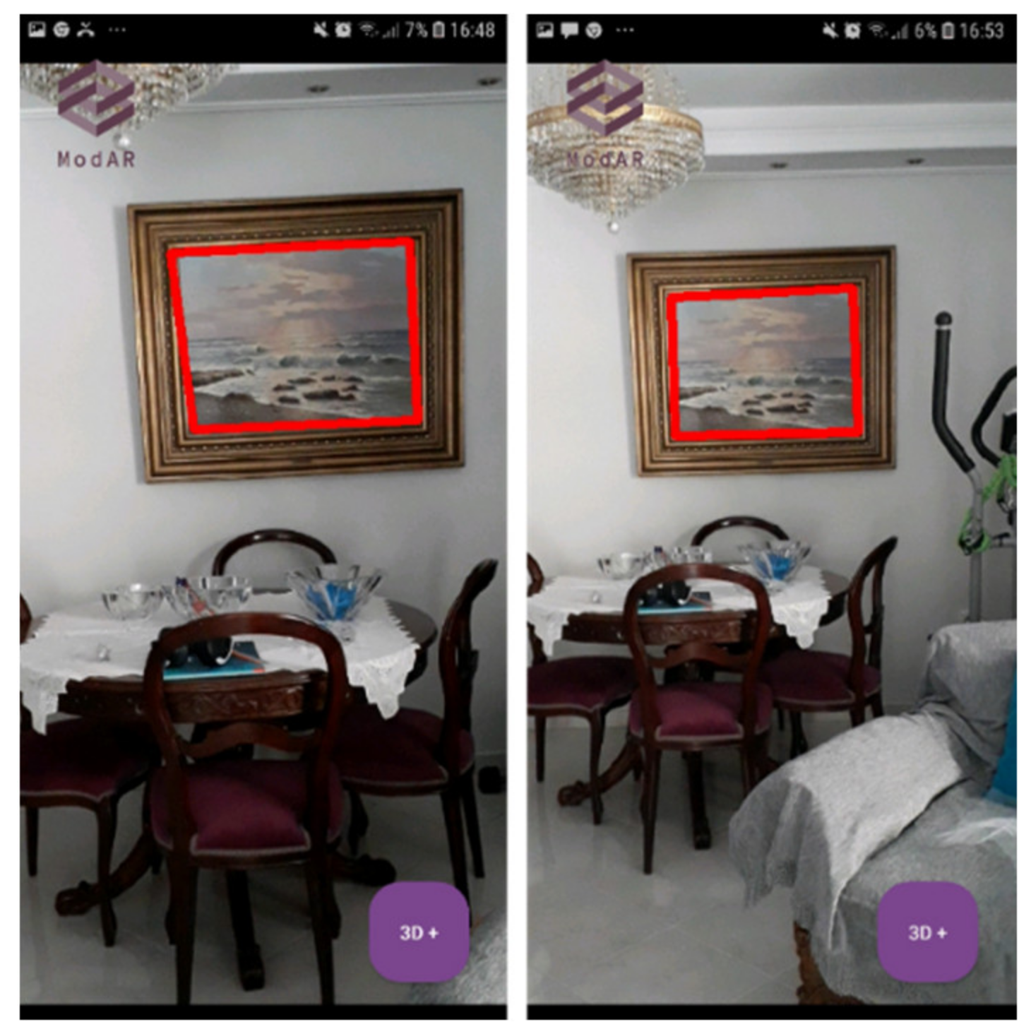
An example of the minimum pattern scale (maximum distance from the pattern object) for which successful pattern recognition is achieved using the two different detectors—descriptors (FAST-ORB-2000 and AGAST-BRISK-3) is illustrated in
Figure 8, where it is observed that BRISK permits pattern recognition in bigger changes of scale than ORB. However, FAST-ORB-2000 yields successful results is an acceptable range of scale, as shown in
Figure 9, where pattern recognition performed by ModAR in camera frames under different scales and rotations as well as different illumination conditions and occlusion is shown.
5.3. AR Rendering
The overall performance of the proposed vertex-data rendering approach that includes instancing, frustrum culling, compressed sub-texturing and VBO grouping, is tested on both devices for the four models separately. The metrics have been collected using Android profiler and system tracing utility. Validation of the results is achieved through average values of three sets of measurements on physical devices. Moreover, the “JEFFERS” pattern image and the combination of FAST-ORB-2000 for the descriptor, detector and maximum number of feature points per image respectively, are selected. For every device and experiment, the base frame rate for video capture is 30 FPS, which practically means that the prototype operates consistently and smoothly at 33.33 ms or less for every screen refresh. If a GPU operation exceeds this limit, a frame drop occurs.
Table 9 reports the results of GPU and CPU profiling at three critical moments of an AR session: on pattern recognition, on 3D model loading and on final display of 3D model. The CPU usage has been recorded for a time period of 40 s.
The prototype delivers an average of 16 FPS and 24 FPS for mid-range and low-end devices, respectively, and less than 30 s of delay when simplified meshes of maximum size of 1.7 MB are overlaid. The AR experience is seamless. The visual quality is high and the duration of loading and drawing phases, before the virtual scene is visualized, is indistinct regarding the potential of the devices. However, the performance and overall experience is degraded in case of the 3D model “CHURCH”, which is significantly larger in size and more complicated (1716× more vertices than “STATUE”). The mid-range device manages to attain a good frame latency distribution maintaining the frame rate half of its maximum value. The single stutter being recorded is not perceived by the end-user, since no animations appear to freeze in the scene. However, the drawing time has significantly increased to 54 s. In the case of the low-end device, the frame drop leads to stutter problems and visible slowness but surprisingly, the geometric fidelity and texture image resolution of the 3D overlay are not degraded. The prototype uses almost the 100% of the CPU processing power of the devices in various phases during the actual drawing. However, frame rates do not drop in proportion to the recorded CPU load, indicating that the latency occurs during GPU processing and is driven by the rendering and not by the computing operations of the Native thread.
These observations stimulate further benchmarking in order to understand the variations in graphics performance. Slow procedures may lie on memory leaks and undesirable memory allocation patterns; thus, a replication of the AR testing session for the 3D model “CHURCH” is conducted using the Memory Profiler tool. The detailed timeline of memory usage for the first 40 s upon pattern recognition for the low-end and the mid-range device is presented in
Figure 10a. The memory type with the most increased memory consumption are Graphics (yellow), i.e., the GPU-CPU shared memory used by the graphics buffer queues. The Native type (dark blue) that represents the objects allocated from the C++ compute thread, consumes an average of 84% less amount of memory than the Graphics type. The low memory footprint showcases its increased performance in computationally intensive tasks like features detection and tracking. Size information for the allocated objects of the rendering classes is provided by running an advanced memory profiling test under the same conditions. The quantity of memory of the ten classes with the most heap count in Graphics memory, are presented in
Figure 10b.
The classes
ObjLoader and
ObjParser of the developed 3D engine as well as the
mRenderer of the rendering thread generate the largest number of temporary objects and impose time restrictions on prototype’s memory allocation per frame. When attempting to render and load a huge volume of vertices on low-memory devices, performance issues with excessive demands on CPU arise, like the memory leak that happened during the 20–25 s on the low-end device (
Figure 10b). Furthermore, UV texture mapping has a significant memory instances count. Therefore, techniques compatible with OpenGL ES 2.0 such as vertex-data re-ordering, organization on VBOs and texture compression are essential for the overall performance amelioration.
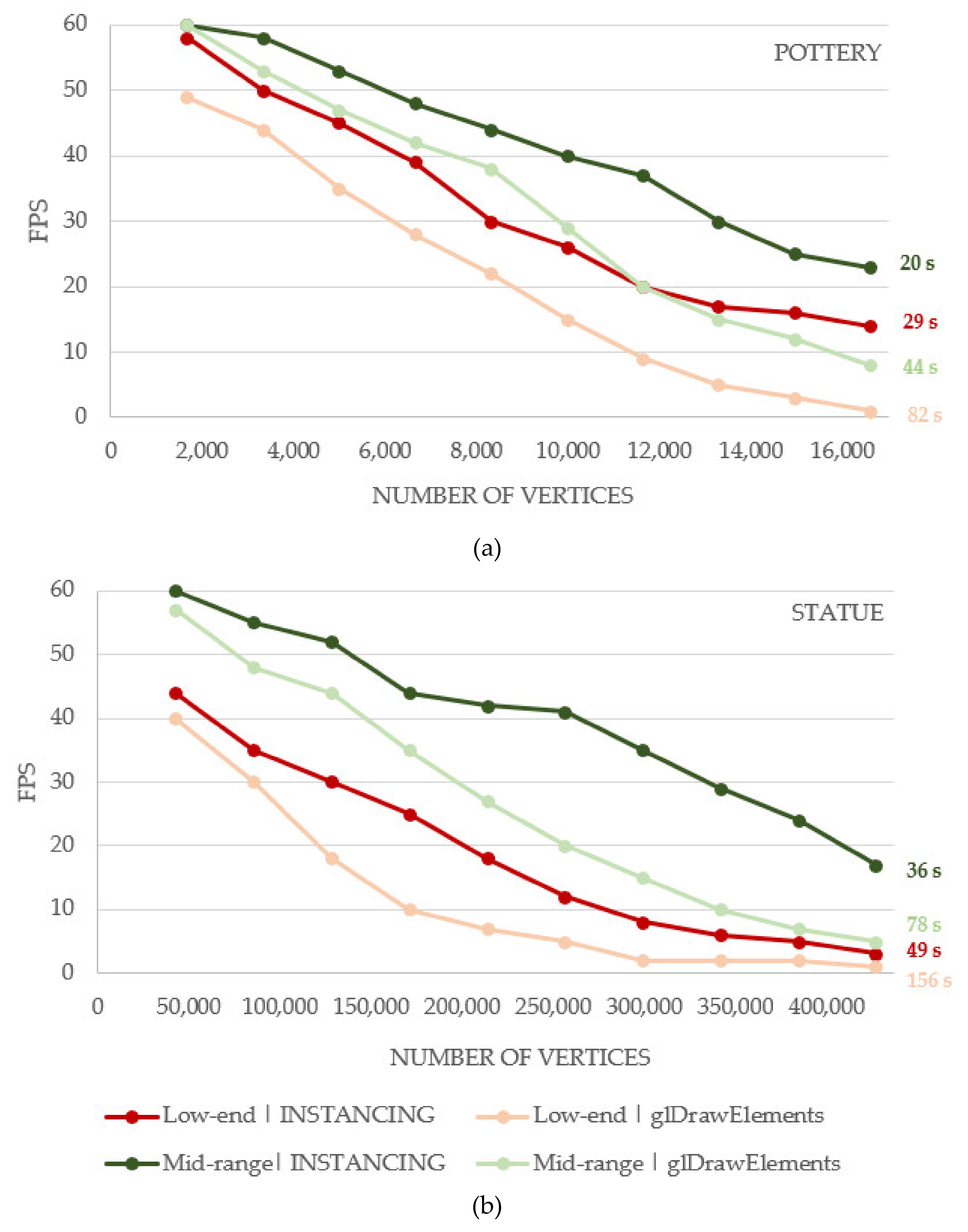
The proposed optimizations applied to the developed 3D graphics engine are compared with standard rendering methods to determine their impact and efficacy. The techniques of (i) instancing and (ii) vertex-data organization are tested individually. In every comparative test, the OpenGL ES commands of each technique are organized in groups using markers and annotated with descriptive labels. For geometry instancing evaluation, two separate sessions with the 3D models “POTTERY” and “CHURCH” are created for frame rate of 60 FPS. In the first one, each mesh is drawn ten times with standard index rendering (
glDrawElements) and the second one implements the developed technique that draws ten instances of each mesh in one call. A unique transformation matrix is applied to each of the ten meshes in both cases, in order to replicate a real AR usage scenario. Total rendering time as well as the FPS corresponding to the number of vertices being drawn at each frame are presented in
Table 10 and
Figure 11, respectively. The best results are obtained with instancing, as expected. A total of 16,610 vertices for the “POTTERY” and 427,120 vertices for the STATUE are rendered in a single draw call in less than 20 s and 36 s at the mid-range device and 29 s and 49 s at the low-end one. Regarding drawing performance, FPS drop is significant after the seventh instance for both devices when 11,627 and 298,984 vertices are being drawn for “POTTERY” and “STATUE”, respectively. Both sessions render the same number of vertices and it can be concluded that the number of draw calls is the actual bottleneck. However, the “STATUE” has 26 × more vertices and is 10× larger in size than “POTTERY” but rendering during instancing is only 1.14x faster for the low-end and 2.2× slower for the mid-range device. The increased rendering tine can probably be attributed to the texture file of “POTTERY” which needs to be accessed and fetched from texture cache memory while GPU is running at the main thread.
Evaluation of the geometry processing stage involves testing vertex fetching efficiency. The testing environment comprises the 3D models “POTTERY” and “STATUE”, grouped in the same vertex buffer object with half float coordinates in the normalized model space. The previous testing session is replicated and executed three times for both devices. The ten meshes of each model are rendered with the standard
glDrawElements() rendering arrays and the developed VBO format using both index rendering and instancing. The average frame rate and the total rendering time of each combination are presented in
Table 11 and
Table 12. Storing groups of 3D models in the same VBO provides significant performance stability for the low-level device and a 3.7× speed gain for the textured model “POTTERY” and a 3.14× for the model “STATUE” with per vertex color for the standard index rendering. In both devices, higher frame rates were achieved for “POTTERY” model compared to the fixed CPU array storages. This result indicates the increased efficiency of GPU memory types in attributes transfer, like texture coordinates and relevant bindings.
6. Conclusions
In this article, a planar pattern-based MAR prototype, named ModAR, is presented. It targets low-end mobile devices which are not certified or cannot enable AR technology, as they lack computational power, compatible operating system version and/or specific hardware. This user group is rarely considered as a target for AR development.
Several deployment scenarios were implemented to detect the optimized computer vision and rendering methodology for the developed prototype. The pose of the 3D models proved to be well aligned with the pattern image for all tested detectors–descriptors combinations, identifying only minor misalignments after a certain camera distance from the object. In response to the lack of commercial and research solutions to limited resources, ModAR attains good precision in positioning and high frame rates. ModAR does not exceed the size of 400 KB and the evaluation tests on low-end and mid-range smartphones demonstrate that it achieves 93% pattern recognition accuracy and thus accurate camera pose estimation for camera frames where the resolution of the pattern in the frame is 0.5 to 0.9 times the resolution of the pattern image, as well as 100% pattern recognition accuracy for camera frames where the resolution of the depicted pattern is 0.9 to 5 times the resolution of the pattern image, regardless of any in-plane rotation. The oriented FAST detector with an upper threshold of 2000 feature points per frame combined with the ORB descriptor were used in the prototype, as they proved to yield the best results in terms of robustness and efficiency. The experiments showed that while the use of the AGAST-BRISK combination of detector–descriptor improves the recognition accuracy by 2–4% (depending on the parameterization used), the loss in speed is dramatical, as the FAST-ORB combination achieves 90% reduction in image matching time compared to the time required by the AGAST detector and the BRISK descriptor.
In turns, performance analysis and extensive benchmarking on the graphics techniques and strategies compatible with the OpenGL ES 2.0 showcased the efficacy of the developed 3D engine and rendering scheme for large vertex data. In less than 30 s and with an average stable frame rate of 20 FPS for low-specification devices, a medium sized textured 3D model is drawn and overlaid the real scene. The AR experience is delightful at no expense of visual quality, even for large volume data, exceeding 7 M vertices. The proposed combination of VBO data grouping, geometric instancing, sub-texturing as well as vertex data types simplification and frustrum culling, can speed up graphics processing of OBJ files up to 3× compared to standard rendering methods.
The developed compute system is able to identify and estimate the pose of the 3D models in various situations (indoors/outdoors) depending on the input pattern image, thus allowing the methodologies employed in this work to be further extended or optimized. Future work involves further optimization of the presented workflow for acceleration of the AR augmentation; investigation into fully-automatic camera calibration of the mobile devices; further experiments of the ModAR prototype to augment outdoor CH sites with high-resolution 3D models; and performance of a subjective study in order to understand and quantify user experience as well as to evaluate the quality of service.


