1. Introduction
Electrification of the powertrain is a big challenge for the current automotive industry [
1]. One of the criticalities of this research area is the improvement of performance, fuel economy and driveability of Hybrid Electric Vehicles (HEV) [
2]. Amongst the current hybrid powertrain architectures, the Power-Split Continuously Variable Transmission (PS-CVT) is the most promising technology, since HEVs often present multiple power sources that can be well managed by transmissions with multiple inputs [
3].
Continuously Variable Transmissions (CVTs) were studied as early as late 19th century, when it was recognized that varying the drive ratio during vehicle operation would improve the performance [
4]. Of the early designs, there have only been a few that have received significant attention from automotive designers. These CVTs can be classified into five categories, depending on their working principle: friction, traction, hydrostatic, electric, and variable geometry [
5]. Conventional CVT units presents some limitations such as limited torque capacity and ratio coverage when compared to conventional units [
6]. It has been proven that it is possible to overcome these limitations by combining the CVT with one or more epicyclic gears to create a power-split transmission [
7].
An example of an early power-split design is the Perbury transmission proposed in 1940 and based on a toroidal variator (traction type CVT) and a planetary gear-set [
8]. Interest in power-spit technology for automotive applications began in the 1980s. Products of this renewed interest are the Toyota Hybrid System and the Allison Hybrid Synergy by General Motors [
9]. Since then, researchers have been attracted by this architecture [
10]. Volpe et al. [
11] presented an optimization procedure for designing the input and output coupled PS-CVT with higher efficiency. Kim et al. [
12] proposed a two-mode PS-CVT with a mode control strategy to minimize fuel consumption. Zhang et al. [
13] explored potential compound power-split configurations with two planetary gear sets to understand how to design the best compound power-split configuration.
The PS-CVT architectures can be classified as single-mode (i.e., input split or output split) or multi-mode, in which the power split type is selected engaging and disengaging clutches included in the transmission layout. In general, single-mode PS-CVTs show low efficiency at high speed when compared to more complex solutions that include at least two epicyclical gear trains and one or more locking systems [
14,
15,
16]. These solutions are also called compound type power split and an example is given by Global Hybrid Cooperation, a joint project by GM, Daimler, and BMW [
17].
Our research group has recently studied the power flows and efficiency of the PS-CVT [
18,
19,
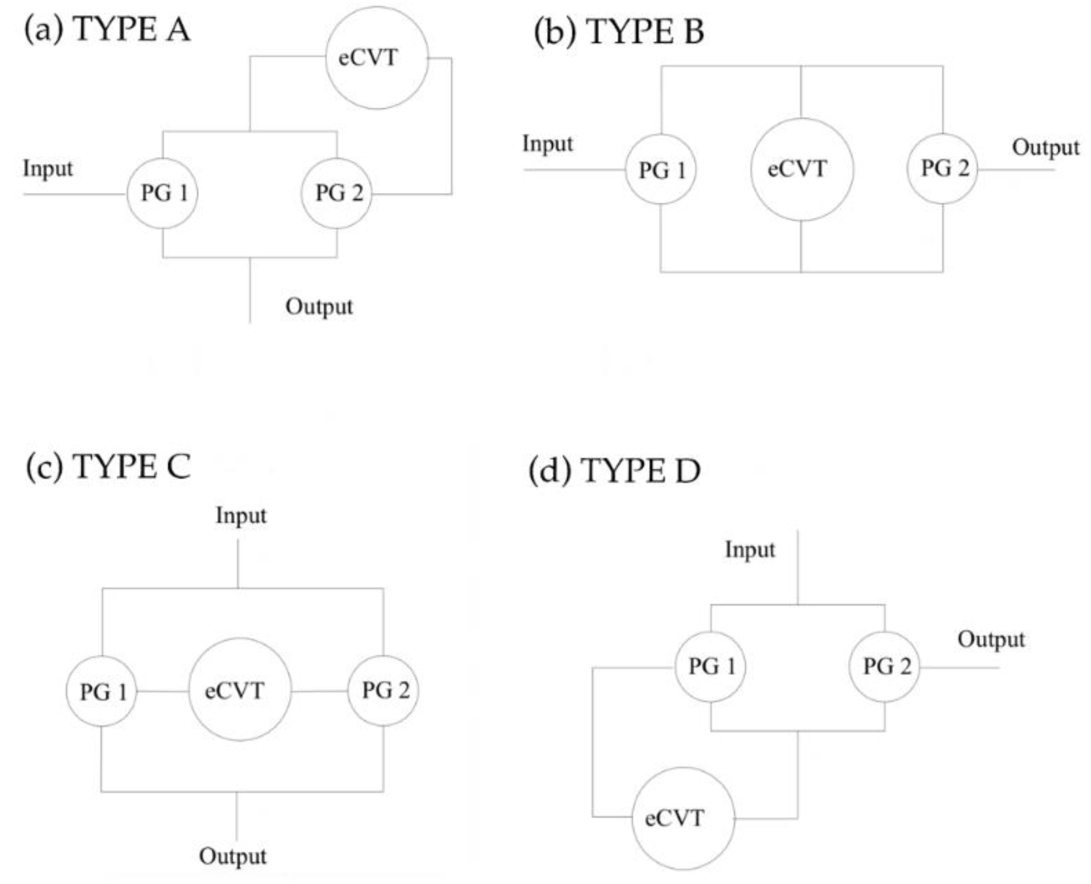
20]. In these previous works, the analysis of a “four-port-mechanical-power split device” was proposed. This device consists of an electric Continuously Variable Transmission (eCVT) and a power split device (
Figure 1). The former is obtained connecting two electric motors; the latter is composed by two planetary gear sets named PG1 and PG2.
Figure 1 shows the four possible set-ups. While types A, B and D have been discussed in [
18,
19,
20], in this paper, we focus on type C. The power flow and the efficiency of this “four-port-mechanical-power split device” are defined and its performance assessed with a numerical example.
The practical value of this paper is to provide the designer of such architecture with a tool to estimate advantages and disadvantages of implementing this topology within a powertrain, e.g., the type of power flow that will occur, the power that will flow in the eCVT and the overall efficiency, knowing just the design parameters, that are the geometry of the planetary gear trains, the ratio spread of the eCVT and the required overall speed ratio spread.
Section 2 shows the formulation of the kinematic model of the transmission. The types of power flows and the specific conditions at which they occur are presented in
Section 3 together with the derivation of formulas for the efficiency of the whole system.
Section 4 provides a numerical example in which the performance of the transmission is estimated for specific working conditions. Finally, the conclusions of the work are drawn in
Section 5.
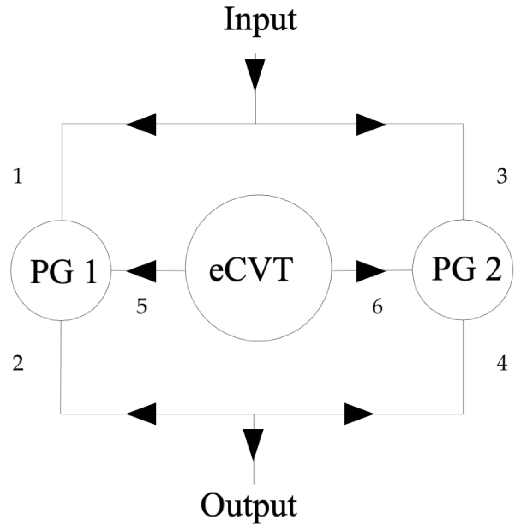
2. Kinematic Model of a Compound Power-Split eCVT
The compound power-split eCVT analyzed in this paper is shown in
Figure 2 and it is one of the possible arrangements of the “four-port-mechanical-power split device”. The shafts are numbered from 1 to 6. In this set-up, the shafts that drive the central gears of the PGs (shafts 1, 2, 3, and 4) are connected to the input and output shafts, while the planet carriers (shafts 5 and 6) are connected to the eCVT. At this stage, it is not specified which one of the two central gears (i.e., sun and ring) of PG1 is connected to shaft 1 or shaft 2, and the same applies to PG2. It is a choice of the designer that depends on the value of the transmission ratio required by the specific application.
The transmission ratios for the PGs and the eCVT are given by (using Willis equation for PG1 and PG2 [
21]):
with:
where
represents the angular speed of shaft j,
is the input speed, and
is the output speed. It is important to specify that the planetary gear ratios
and
are design parameters and therefore constants defined by the geometry of the gears. On the other hand, the global and eCVT speed ratios are kinematic variables, and the design choice regards their spread rather than their instantaneous value that depends on the input and output speeds.
The following speed ratios can be derived from Equations (1) and (2):
Rearranging and combining Equations (1) and (2), the global speed ratio can be derived as a function of the transmission ratios of PGs and eCVT:
The analytical expression of the partial derivative of the global transmission ratio with respect to the speed ratio of the eCVT is derived from Equation (5):
The sign of Equation (6) varies according to the numerator. Therefore, the function
is monotonic for a given set of planetary gear trains. The type of proportionality (namely direct or indirect) between
and
is a design choice. Hereafter, a direct proportionality is assumed, meaning that the following condition must be verified:
The minimum and maximum values of the global speed ratio (namely
and
, respectively) are given by the specific application for which the transmission is designed. These values are related to the limits of the eCVT speed ratio (namely
and
) via Equation (5):
The maximum and minimum eCVT speed ratios are design inputs as well. For this reason, Equations (8) and (9) are useful in the early design stage to determine the characteristics of the planetary gear trains. Indeed, these expressions can be rearranged solving with respect to
and
:
Similar expressions can be easily derived for the case in which indirect proportionality between
is adopted, by imposing:
3. Power Flows
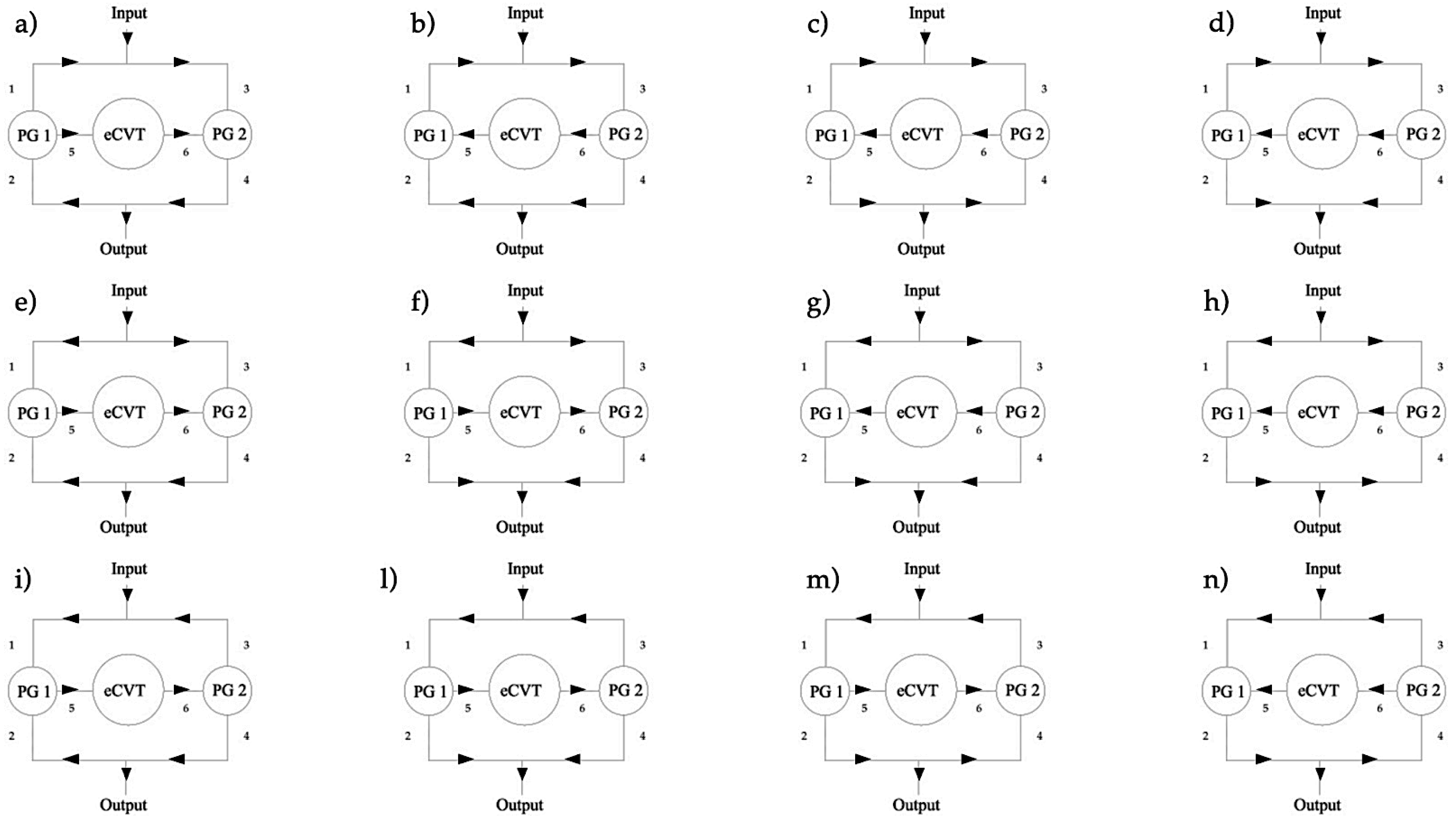
The compound power split devices are subject to several types of internal power flows because of the presence of two planetary gear sets. The objective of this section is to derive the specific conditions at which each power flow occurs in the type C “four-port-mechanical-power split device”. The conditions for each power flow in terms of planetary gears speed ratios are studied in two cases, depending on the sign of the global transmission ratio. The schematics of the twelve possible types of power flows are shown in
Figure 3, while the conditions for each power flow type in terms of power ratio signs are described in
Table 1, where P
j is the power across shaft j. In this paper, P
j is assumed positive when entering the planetary gears. The positive direction of power for all shafts is shown in
Figure 2.
To obtain analytical expressions for the power ratios across the various shafts, the torque ratios must be computed first. Assuming no losses in the planetary gear trains, the following equations can be derived:
From Equations (3), (4), and (14), the following expressions for the power ratios can be obtained:
The sign of the power ratios is not enough to uniquely determine the type of power flow. For example, types a and n present the same combination of power ratio signs, and therefore a further condition is required to distinguish them. The difference between power flows (a) and (n) is in the direction of the power across shafts 1 and 3: power flow (a) occurs when
. From Equation (14), it can be obtained:
From Equations (1) and (16) it follows:
From Equation (17) it can be concluded that power flow type (a) occurs when:
The same consideration applies to power flows (b)–(m) and (c)–(i).
In the next two sections, the sign of the power ratios of Equation (15) and the conditions for each power flow are studied in two cases:
Case 1: ;
Case 2: .
3.1. Case 1:
In the case the global speed ratio is positive,
Table 2 shows the ranges of
and
for each possible power ratio sign as derived from Equation (15). Combining the information in
Table 1and
Table 2, the conditions for each power flow are obtained and shown in
Table 3 where the additional condition refers to Equation (18). These results can be used to uniquely determine the type of power flow that occurs in a specific application of the “four-port-mechanical-power split device”. For example, considering a device designed with
working in a condition in which
, the resulting power flow will be of type (d).
3.2. Case 2:
Similar considerations can be repeated when the global speed ratio is negative. For this case,
Table 4 shows the ranges of
and
for each possible power ratio sign as derived from Equation (15). Combining the
Table 1 and
Table 4, the conditions for each power flow are obtained and shown in
Table 5 where the additional condition refers to Equation (18).
3.3. Efficiency
It has been demonstrated by Cammalleri et al. [
14,
15,
16] that, ignoring losses, the power through the eCVT divided by the power in input to the compound power-split device is given by the following formula, independently of the internal arrangement:
In a real case, the power loss in the transmission is mainly due to the eCVT. The overall efficiency can be derived under the hypothesis that the power losses in the other components are negligible. This assumption is introduced because the efficiency of the eCVT is generally very low compared to the efficiency of the planetary gear trains. With this assumption, the global efficiency can be calculated as follows
The conservation of energy applied to the node connecting the input to shafts 1 and 3 leads to:
If the power in the eCVT flows from left to right, that is when
and
(power flows (a), (e), (f), (i), (l) and (m)), the efficiency of the eCVT is given by:
where the signs of the powers refer to
Figure 2. From the conservation of energy across the eCVT, the power loss in the eCVT is given by:
Combining Equations (15), (20)–(23) the global efficiency can be derived as a function of the characteristic transmission ratios and of the efficiency of the eCVT:
If the power in the eCVT flows from right to left (
and
, power flows (b), (c), (d), (g), (h) and (n)), the efficiency of the eCVT is given by:
From the conservation of energy across the eCVT, the power loss in the eCVT is given by:
Combining Equations (15), (22), (23), (25) and (26) the global efficiency is given by:
In conclusion, the purpose of this approach is to develop a tool to study the advantages and disadvantages of the type C compound power-split device and to evaluate its performance and the power flow obtained within the system. In the design stage, knowing the input design parameters (namely the ranges of global and eCVT speed ratios), the parameters of the planetary gears are obtained with Equations (10) and (11) (assuming direct proportionality between global and eCVT speed ratios). Once the components of the transmission are designed, the
Table 3 and
Table 5 show the type of power flow according to the kinematic parameters of the transmission. Equations (19), (24), and (27) can be used to estimate the power flowing through the eCVT and the efficiency of the whole system.
4. Numerical Example
In this section the performance of the type C “four-port-mechanical-power split device” (
Figure 1c) is evaluated through a numerical example. This kind of architecture is often used as part of a more complex compound transmission and engaged in a specific speed range, as for example shown by Zhang et al. [
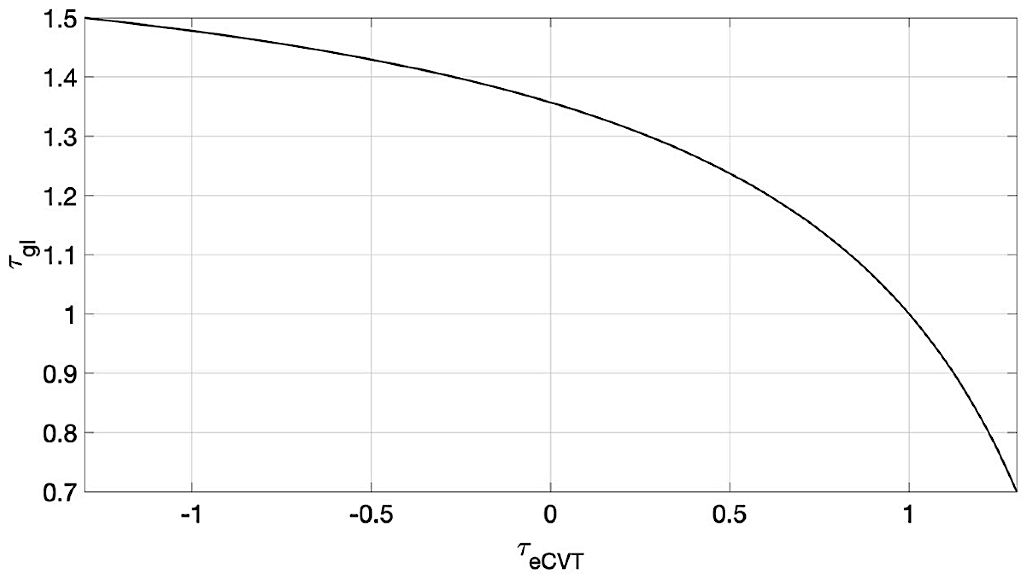
13]. Assuming that we are designing a complex compound power split transmission that changes configuration depending on the speed range, we can decide to engage the topology presented in this paper when the global transmission ratio is between 0.7 and 1.5.
The input design parameters are therefore chosen as follows:
Assuming inverse proportionality between global and eCVT speed ratios, the corresponding values of the planetary gear ratios are calculated with Equations (12) and (13):
Figure 4 shows how the global transmission ratio varies as a function of the speed ratio of the eCVT (Equation (5)).
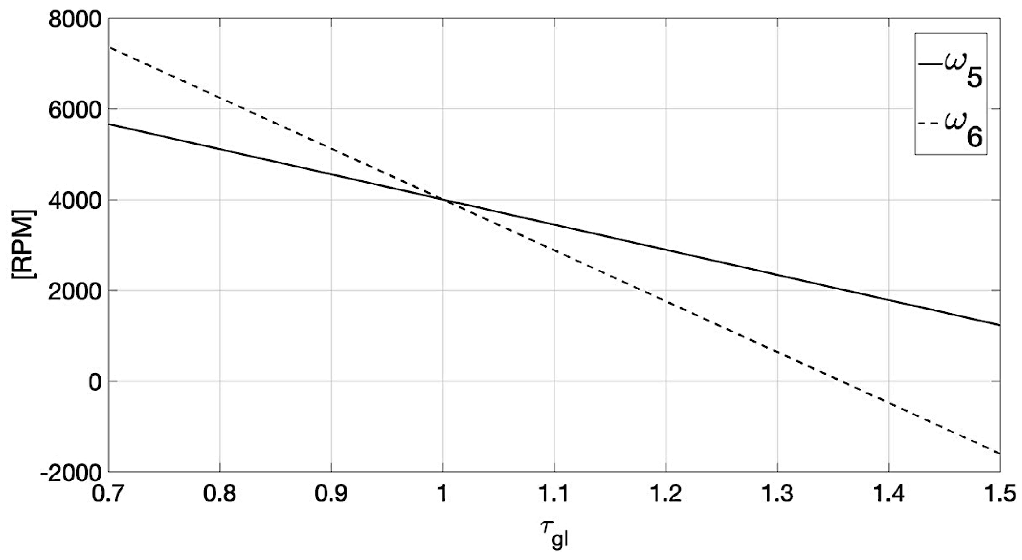
Although the input parameters obtained so far appear reasonable for conventional eCVT and planetary gear trains, it is important to assess the feasibility of the application by checking the speed of the two electric machines in the eCVT (namely,
and
). Assuming a constant input speed of 4000 RPM,
Figure 5 shows the speed of the electric machines (Equation (4)), as a function of the global transmission ratio. The highest speed is reached by the electric machine connected to shaft 6, which spins at a rate of 7360 RPM when the global transmission ratio is 0.7. Considering that conventional electric machines can work up to 9000 RPM [
22], it is safe to accept these speed ranges.
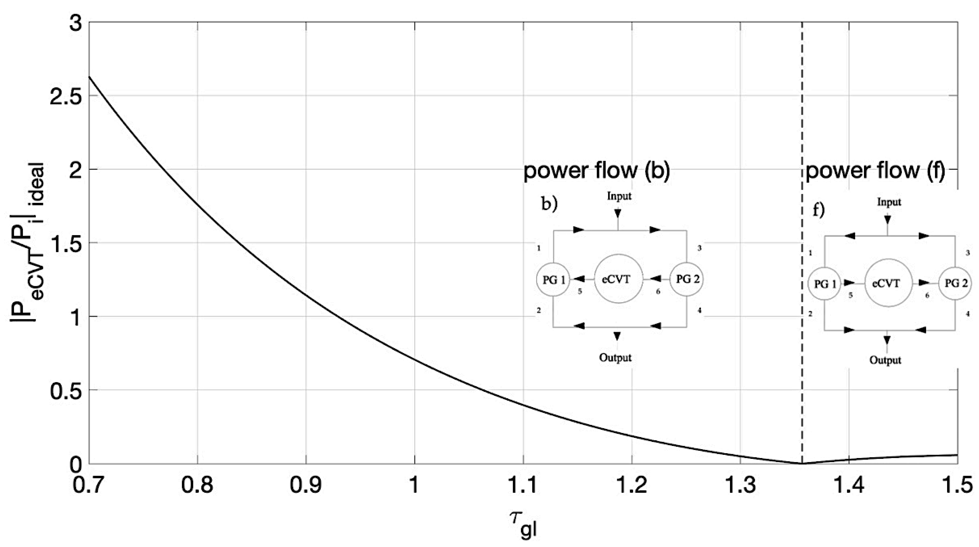
The fraction of power through the eCVT in the ideal case
is plotted in
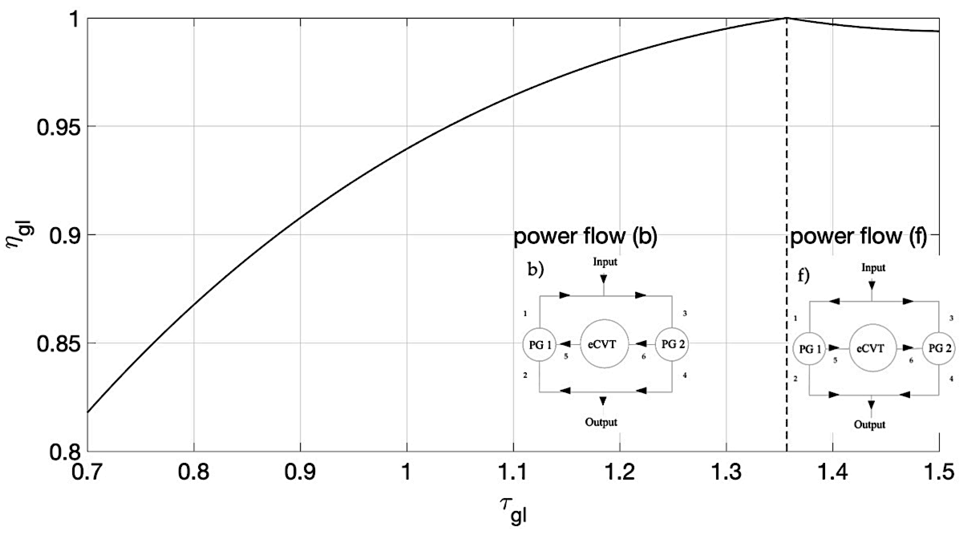
Figure 6 as a function of the global transmission ratio, as obtained from Equation (19). The efficiency of the whole system is shown in
Figure 7 as a function of the global transmission ratio, where the efficiency of the eCVT is assumed equal to 0.9.
In the plots of
Figure 6 and
Figure 7, two different areas can be identified and each one corresponds to a different type of power flow. For values of the global speed ratio between 1.357 and 1.5 power flow (f) is established in the transmission (
Figure 3f). In this case, the efficiency is calculated with Equation (24) because the power through the eCVT flows from left to right. For
between 0.7 and 1.357, power flow (b) occurs, and the efficiency is calculated with Equation (27) because the power through the eCVT has changed direction, flowing from right to left.
The use of the type C architecture for this application is justified by the improved efficiency of the whole system, which is much higher than the efficiency of the eCVT for most of the range of the global transmission ratio (
). This is explained by the fact that in the same region, the power flowing through the eCVT, that is the only source of power losses, is lower than the input power (
). This condition is verified by definition for the case of power flow (f), because the input power splits twice before entering the eCVT, first between shafts 1 and 3, and then between shafts 5 and 2
Figure 3f). This means that power flow (f) is always advantageous. In the case of power flow (b), the power through the eCVT is low when the global transmission ratio is between 0.88 and 1.357, indicating that no recirculation occurs. However, when the global transmission ratio goes below 0.88 a significant fraction of the input power recirculates through the eCVT, making the overall efficiency drop.
The drop in efficiency for low values of the global transmission ratio suggests that this topology would be better suited as a part of a more complex compound transmission, in which a system of clutches and brakes allows the user to change the architecture, choosing one of the four configurations (
Figure 1), connecting shafts 1, 2, 3, 4, 5, and 6 accordingly.
5. Conclusions
This work focused on the evaluation of a compound power split device. The analyzed transmission module is a type C four-port power split device. The twelve types of possible power flow configurations were studied and the conditions at which each power flow occurs have been derived. The main motivation behind this research was to study the selected transmission topology and its properties, which will allow designers and practitioners to estimate advantages and disadvantages of implementing this architecture within a complex compound powertrain. A numerical example was proposed in which a type C compound power split transmission is used. It was concluded that, although the efficiency of the system is higher than the efficiency of the eCVT for most of the global transmission ratio range, this topology would be better suited as a part of a more complex compound transmission to be engaged in a specific speed range.
This work completes the in-depth study of the possible configurations of the four-port power split device. Knowing the bounds of the eCVT and global speed ratios, the models developed in these works establish an original approach by which is possible to evaluate:
The main asset of the four-port power split device is that it is possible to design a system of clutches and brakes that allows the user to change the architecture, choosing one of the four configurations, connecting shafts 1, 2, 3, 4, 5, and 6 accordingly. The objective for future works is to develop an optimization tool that identifies the most efficient configuration for each working condition. Ideally, this tool will help designers to choose the best kinematic parameters (eCVT and planetary gears speed ratios) and obtain an optimum four-port power split device for each specific application.


