Abstract
In this paper, we consider two mechanisms capable of inducing strain localisation in particulate geomaterials in compression: the apparent negative stiffness and the incremental incompressibility caused by dilatancy. It is demonstrated that the apparent negative stiffness can be produced by the rotation of clusters of particles in the presence of compression. The clusters are formed by connecting the particles by the bonds that still remain intact in the process of bond breakage in compression. We developed a 2D isotropic model of incremental incompressibility showing that a single strain localisation zone is formed inclined at 45° to the direction of axial compressive loading. This mechanism of localisation was analysed through Particle Flow Code (PFC) 2D and 3D simulations. It is shown that, in the simulations, the peak stress (the onset of localisation) does correspond to the incremental Poisson’s ratio, reaching the critical values of 1 (in 2D) and 0.5 (in 3D).
1. Introduction
Failure of heterogeneous or particulate materials in compression is a phenomenon important in different engineering fields such as mining, petroleum, and construction. Failure in compression is often preceded by strain localisation, whereby the deformation field becomes nonuniform, with the highest values of strain concentrating in a narrow zone inclined to the direction of compression, eventually leading to so-called shear failure. Strain localisation is often considered as a form of material instability. One of the possible mechanisms of strain localisation in the process of displacement-controlled loading is the emergence of areas of apparent negative stiffness caused by detachments and subsequent rotation of the material constituents.
Negative stiffness stipulates that the directions of the force and displacement are opposite to each other such that, in order to increase deformation, the force needs to be reduced. While negative stiffness signifies negative elastic energy, which excludes the stability of such structures, in some cases, they can be stabilised by inserting into an encompassing (and sufficiently stiff) system such that the total energy of the compound system is positive (e.g., [1,2]). Some systems do exhibit negative stiffness. For instance, negative stiffness is detected in hair bundles in the ear and some joints in human body [3,4,5]. It is observed in post-buckled columns, shells, and L-frames when the loading frame is sufficiently stiff [6,7,8]. Multiwalled carbon nanotubes have also been found to exhibit negative stiffness [9,10,11]. The negative stiffness effect can be observed in some topological interlocking assemblies [12], as well as in specially engineered structures consisting of elastic elements such as links and levers with springs [13,14,15,16], arches [17], and structures with magnetic elements [18]. The latter are based on the fact that the magnetic force reduces with the distance, thus producing the effect of negative stiffness. The macroscopic negative stiffness phenomenon can occur in composite materials that contain negative stiffness inclusions [19,20]. Apparent negative stiffness is also exhibited by various auxetic systems (e.g., [18,21]). A number of applications of negative stiffness have been envisaged. A negative stiffness-based loading bearing structure was proposed in [22]. Devices of negative stiffness have been developed for the seismic protection of structures, car seat suspensions [4,23,24,25,26], and vibration isolation [27,28,29,30,31,32,33]. A novel actuator that combines positive and negative stiffness mechanisms was proposed in [32], and a three-dimensional base isolation system that uses a negative stiffness device was discussed in [33]. The dynamics of rotation of non-spherical particles was studied by modelling the system as an inverted pendulum under displacement-controlled loading [34]. The conditions of stability of materials with negative stiffness elements and the methods of stabilisation were discussed in [34,35,36,37]. Negative compressibility in some anisotropic materials [38] leaves the energy positive definite (see also [39]); such situations are not considered here.
Incremental negative stiffness (when strain is increasing) is also observed in the loading of many rocks, concrete, and granular materials during the post-peak softening stage (e.g., [39,40,41,42]), i.e., the stage of stress–strain relationship obtained in displacement-controlled loading when stress decreases with strain increase. As the post-peak softening stage is usually preceded by strain localisation, we assume that the negative stiffness can constitute one of the localisation mechanisms.
Another possible mechanism of strain localisation is the emergence of a state of incremental incompressibility (incompressibility in terms of stress/strain increments) emerged due to dilatancy (inelastic volume increase due to fracture propagation in the sample in compression). The aim of the paper was to analyse these two mechanisms of strain localisation in particulate materials (materials composed of bonded particles): the mechanism based on formation and rotation of particle clusters and the emergence of incremental incompressibility. These localisation mechanisms are discussed and illustrated using the results of 2D and 3D discrete element simulations.
2. Apparent Negative Stiffness Created by Rotation of Clusters of Particles
Consider the Dyskin and Pasternak [1] rotation of a partially detached non-spherical particle in a granular material. Such a particle can represent either non-spherical grains or clusters of grains, even when the grains themselves are spherical (Figure 1). In Figure 1, T and P are the forces created by the shear and uniaxial compressive stress, d is the length of the line between the two contact points (cluster diameter), α is the initial angle between this line and the vertical direction, and u is the shear displacement due to rolling. The moment equilibrium about O is expressed as
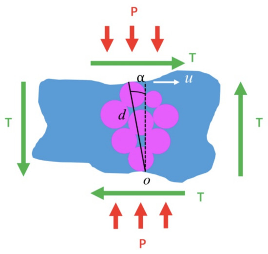
Figure 1.
Partially detached cluster of particles within matrix. Two pairs of forces are shown in order to emphasise that moment equilibrium should hold.
Normalisation of Equation (1) by (assuming the positions with ) gives
By denoting , , Equation (2) can be transferred to the following form:
Examining Equation (1) shows that, as the rolling progresses, the term inside the square root on the left-hand side of the equation increases. On the right-hand side, the term inside the bracket decreases. If P is fixed, then the shear stress must be decreasing to keep the moments about O in equilibrium. The slope of the decrease, . Thus, the apparent negative stiffness is produced by rolling of a non-spherical cluster of particles in compression. This effect was also seen in PFC 2D simulations presented in [43]. In the case of loaded samples that exhibit negative stiffness, the stability of the sample with negative stiffness is ensured by the boundary conditions which represent an encompassing positive stiffness loading frame. In this case, the energy of the system consisting of the sample plus the loading frame is positive definite [1,2,43].
In order to illustrate the existence of rotating clusters, a 2D discrete element simulation of uniaxial compression test on a sample of particulate material was conducted. The virtual sample was created by randomly placing particles with radii between Dmin and Dmax = DrDmin, where Dr is the maximum to minimum disc diameter ratio, until the target porosity was reached. This was performed in four steps: (1) the initial unbonded compact virtual sample was built within four frictionless walls; (2) floaters, i.e., the particles with no contact with other particles, were deleted; (3) the particle bonds were installed, leading to the particles being “glued” together; (4) the initial frictionless walls were removed, and the sample was relaxed by performing the modelling such that the average displacement became less than 10−6 of the average disc radius. This procedure produced a sample containing 3786 particles. The built-in linear parallel bond model was used as the contact bond model. This bond model represents bonds between particles that are able to break one-by-one, eventually separating particle clusters and leaving them free to rotate. It is assumed that the bond breakage takes place only when the force acting on it reaches the tensile strength of the bond. Parameters of the virtual sample are shown in Table 1 and Table 2.

Table 1.
Parameters of the virtual sample. H, W, Dmin, Dr, and are the sample height, sample width, minimum disc diameter, maximum to minimum disc diameter ratio, and density of the particles.
Table 2.
Parameters of contact and parallel bond model. E, Ep, , , and are the contact effective modulus, parallel bond effective modulus, parallel bond mean tensile strength, parallel bond tensile strength standard deviation, and parallel bond shear strength.
In the simulations, we set the bond shear strength to a very high value to exclude bond shear failure, which follows the hypothesis proposed in [44] that micro-tensile failure can act as a global failure mechanism of particulate materials. The properties of the interparticle bond, as well as the procedure of virtual sample generation, follow the method proposed in [45]. The boundary conditions were as follows: (1) the top and bottom walls converged at a small constant velocity, which also follows [45]; (2) no external loads or objects to the right and left sides of the virtual sample were applied.
Particle rotations at the end of the test are shown in Figure 2. The rotations were observed at a stage where the axial stress of the sample reached 99% of the peak stress (the pre-peak region of stress–strain curve). The colour scale refers to the angles of particle rotations in degrees. In the process of loading, 378 bonds were fractured. Particles outside the lateral boundaries were detached from the main virtual sample due to fracture generation. It can be seen that, at the bottom left corner of the virtual sample, there was a cluster of particles rotating in the anticlockwise direction at about the same angle, which was equivalent to the cluster rotating as a whole at the same angle. There are also other similar clusters of simultaneously rotating particles determinable in Figure 2. Obviously, the shape of this cluster was not spherical (circular); therefore, when it rotated under compression, it produced an apparent negative stiffness effect.
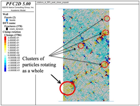
Figure 2.
Clusters of particles rotating in the same direction (rotations are counted with respect to the initial positions of the particles). The colour scheme is shown on the left side of the picture; the angles are in radians.
3. Incrementally Incompressible Material-Fundamentals
We discussed in [45] that incompressible elastic isotropic materials can allow non-trivial stress distributions in the absence of loading. Here, we further this concept and analyse a possible structure of such a stress distribution and determine if it can cause strain localisation. Consider a sample of particulate material (e.g., rock or concrete) in uniaxial compression under a constant lateral pressure (can be zero), as shown in Figure 3.
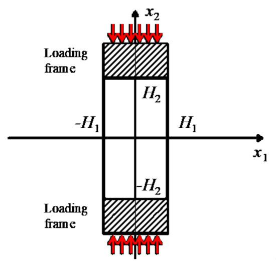
Figure 3.
A 2D model of a sample of particulate material under uniaxial compression applied through a stiff loading frame.
Under compression, the load particulate materials exhibit dilatancy, which is a nonelastic increase of the volume. Incrementally, the effect of dilatancy leads to an apparent increase in Poisson’s ratio such that the material can reach (and even exceed) the state of incompressibility (in plane strain, the 2D approximation we use here, the Poisson’s ratio is equal to 1). It needs to be emphasised that dilatancy is irreversible; hence, strictly speaking, the incompressibility is achieved only when the load increment is positive (compression is considered to be positive). This property was used in selecting the appropriate nontrivial (nonzero) solution of the incremental equilibrium equations.
In 2D, Hooke’s law and equilibrium equations for an incompressible elastic isotropic medium in the coordinate frame shown in Figure 3 lead to the following equations:
where E is the incremental Young’s modulus, and are incremental displacement, strain, and stress, respectively.
A nontrivial solution of Equation (5) is sought in the complex form
where are parameters and . Substituting this form into Equation (5) leads to a singular system for any unit vector k = (k1,k2). Furthermore, it is shown that ; therefore,
Substituting Equation (7) into the condition of incompressibility (second equation in Equation (4)) gives . Since , one can write
The obvious boundary conditions written in stress increments at the lateral surface are . According to Equations (6) and (7), ; hence, . Therefore, the second boundary condition is satisfied automatically. The first boundary condition due to incompressibility leads to .
From Equations (6) and (8), one obtains
By introducing
Strain in Equation (9) can be rewritten as
Since the dilatancy producing incompressibility is irreversible, only positive strains (compression is assumed positive) should be considered. Because the argument in Equation (11) can be both positive and negative, the only admissible solution is
This dependence represents strain localisation along either vector (1, 1) or vector (1, −1), i.e., the strain localisation lines are inclined to the loading axis x2 at 45°. The stress increments are not determinable in this approximation.
4. Incremental Incompressibility in 2D and 3D Simulations
In order to illustrate strain localisation in uniaxial compression of particulate materials induced by incremental incompressibility, we conducted 2D and 3D discrete element simulations of uniaxial compression of samples consisting of circular/spherical particles connected by breakable bonds.
4.1. 2D Simulations
For the 2D case, the critical value of incremental Poisson’s ratio is equal to 1. In order to verify that critical value, we performed 2D simulations of the uniaxial (unconfined) compressive test. The 2D sample consisting of 3786 particles was generated as explained in Section 2. The linear parallel bond model was used to simulate particle bonds, as described in Section 2.
In order to determine the incremental Poisson’s ratio, we need to use a suitable time interval, as plotting the Poisson’s ratio timestep by timestep will demonstrate considerable fluctuations. A natural choice of the time interval is the characteristic time of the computational stabilisation. In order to obtain this characteristic time, we applied a step loading to our sample. We then counted the timesteps required for the force on the wall to stabilise. As shown in Figure 4, it took about 4000 computational timesteps for the average force on the wall to be stabilised. Hence, the time that corresponded to 4000 steps was used as the time interval to compute the incremental Poisson’s ratio.
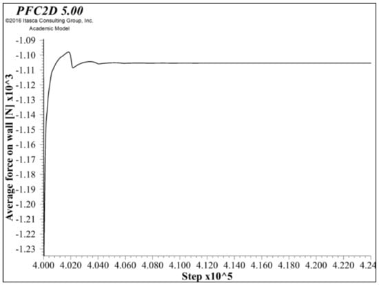
Figure 4.
Characteristic time (in computational timesteps) of a full-sized 2D sample. The horizontal axis numbering starts with actual loading, skipping the stages of sample generation and relaxation.
The incremental Poisson’s ratio is calculated as
where Ln and An are the lateral and axial strain for timestep n.
Figure 5 shows the incremental Poisson’s ratio and axial stress vs. the timestep. It can be seen from the figure that the critical value of 1 of incremental Poisson’s ratio was reached in the peak region.
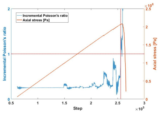
Figure 5.
Incremental Poisson’s ratio and axial stress vs. timestep in 2D simulations.
The localisation pattern of the 2D virtual sample is shown in Figure 6. It can be seen that the localisation pattern does not exactly incline at 45°. The difference between the simulated inclination angle and 45° was due to the fact that the material after microfracturing and dilatancy is no longer isotropic (as assumed) due to stress-induced anisotropy, although the anisotropy and the difference between the localisation angle and 45° are small.
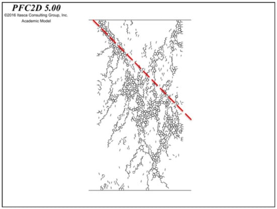
Figure 6.
Localisation pattern in a 2D virtual sample; the load direction is vertical. The broken line indicates the predicted angle of 45° to the loading direction. Deviation of the localisation pattern from the 45° direction is caused by incremental anisotropy induced by the bond breakage that depends upon the direction of the applied compression.
4.2. 3D Simulations
The analogue of incremental incompressibility in 3D is obviously an incremental Poisson’s ratio equal to 0.5. In order to verify that, we performed 3D simulations of the uniaxial compressive test on a cylindrical sample of particulate material. The 3D sample was created using a procedure similar to that for the 2D sample (Section 2). The 3D sample consisted of 15,023 particles, and, similarly to the 2D virtual sample, the linear parallel bond model was used as the bond. Parameters of the virtual sample in 3D chosen for illustration purposes are listed in Table 3 and Table 4.
Table 3.
Parameters of the 3D sample. H, W, Dmin, Dr, are the sample height, sample diameter, minimum disc diameter, maximum to minimum diameter ratio, and density of the particles.
Table 4.
Parameters of parallel bond model of the 3D sample. E, Ep, , , are the contact effective modulus, parallel bond effective modulus, parallel bond mean tensile strength, parallel bond tensile strength standard deviation, and parallel bond shear strength.
The same method as the 2D case was used to obtain the characteristic time for the 3D virtual sample. As shown in Figure 7, it took an interval of about 9000 computational time steps for the average force on the wall to be stabilised. Hence, 9000 was used as the time interval to compute the incremental Poisson’s ratio.
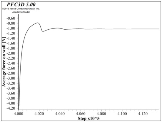
Figure 7.
Characteristic time for the full-sized 3D sample.
Figure 8 shows the plot of incremental Poisson’s ratio (Equation (13)) and axial stress against timestep. It can be seen from Figure 8 that the critical value of 0.5 of the incremental Poisson’s ratio was reached in the peak region. This means that, when the incremental material incompressibility was reached, the model sample exhibited localised deformation, which prevented further axial stress increase in this displacement-controlled loading. Figure 9 shows the localisation pattern of the 3D sample. It is seen that the region of strain localisation was approximately inclined at 45° to the direction of compression.
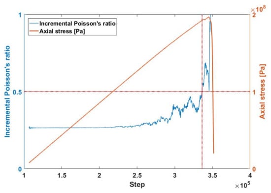
Figure 8.
Incremental Poisson’s ratio and axial stress vs. time (in steps) in 3D simulations.
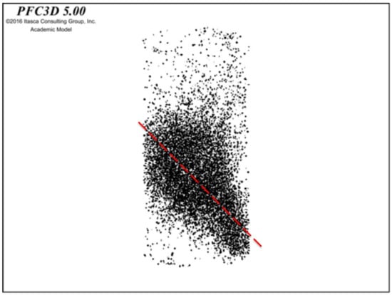
Figure 9.
Localisation pattern of 3D virtual sample; the load direction is vertical. The broken line indicates the predicted angle of 45° to the loading direction.
It can be seen that, while rotations of particle clusters were observed in the discrete element simulations and, hence, the apparent negative stiffness could emerge, it is the incremental incompressibility that provided a mechanism of strain localisation in uniaxial compression. Furthermore, the localisation zones were inclined at approximately 45° to the direction of compression, as follows from the analysis that assumed incremental isotropy of the material. The stress-induced anisotropy leading to deviations from the 45° orientation was apparently low.
5. Conclusions
The failure of particulate materials such as rocks and concretes occurs in the form of splitting, shear failure, or spalling. In this study, we focused on a possible mechanism of strain localisation that precedes shear failure.
Two mechanisms that are candidates for producing strain localisation in particulate materials under compression are the apparent negative stiffness caused by rotating non-spherical constituents in the presence of compression and the incremental compressibility caused by dilatancy. Using discrete element simulations (2D), we demonstrated that the apparent negative stiffness could be induced in the assembly of circular particles when not all the bonds were broken such that rotating clusters were formed. These clusters were not circular and, hence, in the presence of compression, they were capable of producing the apparent negative stiffness similarly to non-spherical (non-circular) particles.
The dilatancy-induced incremental incompressibility in (incrementally) isotropic material was shown to produce localisation zones inclined at 45° to the direction of axial compressive loading. This mechanism of localisation in particulate materials in compression was illustrated through 2D and 3D simulations. The time window needed for determining the stage of incremental incompressibility (the incremental Poisson’s ratio equal to 1 in 2D and 0.5 in 3D) was obtained from the step loading method. It was shown that, in the simulations, the peak stress (the onset of localisation) corresponded to the incremental Poisson’s ratio, reaching the critical values of 1 (in 2D) and 0.5 (in 3D). The localisation zones obtained in the simulation were inclined at approximately 45° to the loading axis; the deviation from the predicted angle could be attributed to the small stress-induced anisotropy.
The results of this study can provide insight into the mechanics of failure of heterogeneous and particulate materials in compression.
Author Contributions
A.V.D.—Conceptualisation, analytical modelling, writing; E.P.—Analytical modelling, writing; Y.X.—Numerical modelling, writing. All authors have read and agreed to the published version of the manuscript.
Funding
The research was funded bu the Australian Research Council Discovery Grant DP210102224.
Institutional Review Board Statement
Not applicable.
Informed Consent Statement
Not applicable.
Data Availability Statement
Not applicable.
Acknowledgments
A.V.D. and E.P. acknowledge support from the Australian Research Council through project DP210102224. A.V.D. acknowledges the support from the School of Civil and Transportation, Faculty of Engineering, Beijing University of Civil Engineering and Architecture.
Conflicts of Interest
The authors declare no conflict of interest.
References
- Dyskin, A.V.; Pasternak, E. Mechanical effect of rotating non-spherical particles on failure in compression. Philos. Mag. 2012, 92, 3451–3473. [Google Scholar] [CrossRef]
- Dyskin, A.V.; Pasternak, E. Elastic composite with negative stiffness inclusions in antiplane strain. Int. J. Eng. Sci. 2012, 58, 45–56. [Google Scholar] [CrossRef]
- Latash, M.L.; Zatsiorsky, V.M. Joint stiffness: Myth or reality? Hum. Mov. Sci. 1993, 12, 653–692. [Google Scholar] [CrossRef]
- Martin, P.; Mehta, A.D.; Hudspeth, A.J. Negative Hair-Bundle Stiffness Betrays a Mechanism for Mechanical Amplification by the Hair Cell. Proc. Natl. Acad. Sci. USA 2000, 97, 12026–12031. [Google Scholar] [CrossRef]
- Choi, A.; Sim, T.; Mun, J.H. Quasi-stiffness of the knee joint in flexion and extension during the golf swing. J. Sports Sci. 2015, 33, 1682–1691. [Google Scholar] [CrossRef] [PubMed]
- Lakes, R.S. Extreme damping in compliant composites with a negative-stiffness phase. Philos. Mag. Lett. 2001, 81, 95–100. [Google Scholar] [CrossRef]
- Lakes, R.S. Extreme Damping in Composite Materials with a Negative Stiffness Phase. Phys. Rev. Lett. 2001, 86, 2897–2900. [Google Scholar] [CrossRef] [PubMed]
- Bažant, Z.P.; Cedolin, L. Stability of Structures: Elastic, Inelastic, Fracture, and Damage Theories; Oxford University Press: New York, NY, USA, 1991. [Google Scholar]
- Yap, H.W.; Lakes, R.S.; Carpick, R.W. Mechanical Instabilities of Individual Multiwalled Carbon Nanotubes under Cyclic Axial Compression. Nano Lett. 2007, 7, 1149–1154. [Google Scholar] [CrossRef]
- Kuzumaki, T.; Mitsuda, Y. Nanoscale Mechanics of Carbon Nanotube Evaluated by Nanoprobe Manipulation in Transmission Electron Microscope. Jpn. J. Appl. Phys. 2006, 45, 364–368. [Google Scholar] [CrossRef]
- Yap, H.W.; Lakes, R.S.; Carpick, R.W. Negative stiffness and enhanced damping of individual multiwalled carbon nanotubes. Phys. Rev. B 2008, 77, 045423. [Google Scholar] [CrossRef]
- Estrin, Y.; Dyskin, A.V.; Pasternak, E.; Schaare, S.; Stanchits, S.; Kanel-Belov, A.J. Negative stiffness of a layer with topologically interlocked elements. Scr. Mater. 2003, 50, 291–294. [Google Scholar] [CrossRef]
- Carrella, A.; Brennan, M.J.; Waters, T.P. Demonstrator to show the effects of negative stiffness on the natural frequency of a simple oscillator. Proc. Inst. Mech. Eng. Part C J. Mech. Eng. Sci. 2008, 222, 1189–1192. [Google Scholar] [CrossRef]
- Sarlis, A.A.; Pasala, D.T.R.; Constantinou, M.C.; Reinhorn, A.M.; Nagarajaiah, S.; Taylor, D.P. Negative Stiffness Device for Seismic Protection of Structures. J. Struct. Eng. 2013, 139, 1124–1133. [Google Scholar] [CrossRef]
- Lee, C.M.; Goverdovskiy, V.N. Type synthesis of function-generating mechanisms for seat suspensions. Int. J. Automot. Technol. 2009, 10, 37–48. [Google Scholar] [CrossRef]
- Lee, C.M.; Bogatchekov, A.H.; Goverdovshiy, V.N.; Temnikow, A.I. Proceedings, KORUS 2003: The 7th Korea-Russia International Symposium on Science and Technology, Ulsan, Korea, 28 June–6 July 2003; University of Ulsan: Ulsan, Korea, 2003; Volume 1, p. 285. [Google Scholar]
- Pontecorvo, M.E.; Barbarino, S.; Murray, G.J.; Gandhi, F.S. Bistable arches for morphing applications. J. Intell. Mater. Syst. Struct. 2013, 24, 274–286. [Google Scholar] [CrossRef]
- Stręk, T.; Maruszewski, B.; Narojczyk, J.W.; Wojciechowski, K.W. Finite element analysis of auxetic plate deformation. J. Non-Cryst. Solids 2008, 354, 4475–4480. [Google Scholar] [CrossRef]
- Lakes, R.S.; Drugan, W.J. Dramatically stiffer elastic composite materials due to a negative stiffness phase? J. Mech. Phys. Solids 2002, 50, 979–1009. [Google Scholar] [CrossRef]
- Wang, Y.C.; Lakes, R.S. Extreme thermal expansion, piezoelectricity, and other coupled field properties in composites with a negative stiffness phase. J. Appl. Phys. 2001, 90, 6458–6465. [Google Scholar] [CrossRef]
- Wojciechowski, K.W.; Scarpa, F.; Grima, J.N.; Alderson, A. Auxetics and other systems of negative characteristics. Phys. Status Solidi B 2015, 252, 1421–1425. [Google Scholar] [CrossRef]
- Churchill, C.B.; Shahan, D.W.; Smith, S.P.; Keefe, A.C.; McKnight, G.P. Dynamically variable negative stiffness structures. Sci. Adv. 2016, 2, e1500778. [Google Scholar] [CrossRef] [PubMed]
- Shi, X.; Zhu, S. Simulation and optimization of magnetic negative stiffness dampers. Sens. Actuators A Phys. 2017, 259, 14–33. [Google Scholar] [CrossRef]
- Palomares, E.; Nieto, A.; Morales, A.L.; Chicharro, J.; Pintado, P. Numerical and experimental analysis of a vibration isolator equipped with a negative stiffness system. J. Sound Vib. 2018, 414, 31–42. [Google Scholar] [CrossRef]
- Attary, N.; Symans, M.; Nagarajaiah, S. Development of a rotation-based negative stiffness device for seismic protection of structures. J. Vib. Control. 2017, 23, 853–867. [Google Scholar] [CrossRef]
- Danh, L.T.; Ahn, K.K. Active pneumatic vibration isolation system using negative stiffness structures for a vehicle seat. J. Sound Vib. 2014, 333, 1245–1268. [Google Scholar] [CrossRef]
- Park, S.-T.; Luu, T.-T. Techniques for optimizing parameters of negative stiffness. Proc. Inst. Mech. Eng. Part C J. Mech. Eng. Sci. 2007, 221, 505–510. [Google Scholar] [CrossRef]
- Mizuno, T.; Takasaki, M.; Kishita, D.; Hirakawa, K. Vibration isolation system combining zero-power magnetic suspension with springs. Control. Eng. Pr. 2007, 15, 187–196. [Google Scholar] [CrossRef]
- Mizuno, T.; Toumiya, T.; Takasaki, M. Vibration Isolation System Using Negative Stiffness. JSME Int. J. Ser. C Mech. Syst. Mach. Elem. Manuf. 2003, 46, 807–812. [Google Scholar] [CrossRef][Green Version]
- Acar, M.; Yilmaz, C. Design of an adaptive–passive dynamic vibration absorber composed of a string–mass system equipped with negative stiffness tension adjusting mechanism. J. Sound Vib. 2013, 332, 231–245. [Google Scholar] [CrossRef]
- Yang, J.; Xiong, Y.; Xing, J. Dynamics and power flow behaviour of a nonlinear vibration isolation system with a negative stiffness mechanism. J. Sound Vib. 2012, 332, 167–183. [Google Scholar] [CrossRef]
- Braun, D.J.; Chalvet, V.; Dahiya, A. Positive–Negative Stiffness Actuators. IEEE Trans. Robot. 2018, 35, 162–173. [Google Scholar] [CrossRef]
- Cimellaro, G.P.; Domaneschi, M.; Warn, G. Three-Dimensional Base Isolation Using Vertical Negative Stiffness Devices. J. Earthq. Eng. 2018, 24, 2004–2032. [Google Scholar] [CrossRef]
- Karachevtseva, I.; Pasternak, E.; Dyskin, A.V. Negative Stiffness Produced by Rotation of Non-Spherical Particles and Its Effect on Frictional Sliding. Phys. Status Solidi B 2019, 256, 1800003. [Google Scholar] [CrossRef]
- Kochmann, D.M. Stability criteria for continuous anddiscrete elastic composites and theinfluence of geometry on the stabilityof a negative-stiffness phase. Phys. Status Solidi B 2012, 249, 1399–1411. [Google Scholar] [CrossRef]
- Wojnar, C.S.; Kochmann, D.M. Stability of extreme static and dynamic bulk moduli of an elastic two-phase composite due to a non-positive-definite phase. Phys. Status Solidi B 2014, 251, 397–405. [Google Scholar] [CrossRef]
- Kochmann, D.M.; Drugan, W.J. Infinitely stiff composite via a rotation-stabilized negative-stiffness phase. Appl. Phys. Lett. 2011, 99, 011909. [Google Scholar] [CrossRef]
- Grima, J.N.; Caruana-Gauci, R.; Wojciechowski, K.W.; Evans, K.E. Smart hexagonal truss systems exhibiting negative compressibility through constrained angle stretching. Smart Mater. Struct. 2013, 22, 084015. [Google Scholar] [CrossRef]
- Lakes, R.S.; Wojciechowski, K.W. Negative compressibility, negative Poisson’s ratio, and stability. Phys. Status Solidi B 2008, 245, 545–551. [Google Scholar] [CrossRef]
- Cook, N.G.W. The failure of rock. Int. J. Rock Mech. Min. Sci. 1965, 2, 389–403. [Google Scholar] [CrossRef]
- Salamon, M. Stability, instability and design of pillar workings. Int. J. Rock Mech. Min. Sci. Géoméch. Abstr. 1970, 7, 613–631. [Google Scholar] [CrossRef]
- Pasternak, E.; Dyskin, A.V.; Esin, M.; Hassan, G.M.; Macnish, C. Rotations and pattern formation in granular materials under loading. Philos. Mag. 2015, 95, 1–24. [Google Scholar] [CrossRef]
- Dyskin, A.V.; Pasternak, E.; Xu, Y. Behaviour of extreme auxetic and incompressible elastic materials. Phys. Status Solidi B 2017, 254, 1600851. [Google Scholar] [CrossRef]
- Dyskin, A.V.; Pasternak, E. Mechanism of in-plane fracture growth in particulate materials based on relative particle rotations. In Proceedings of the 13th International Conference on Fracture, Beijing, China, 16–21 June 2013; pp. 725–734. [Google Scholar]
- Potyondy, D.O.; Cundall, P.A. A bonded-particle model for rock. Int. J. Rock Mech. Min. Sci. 2004, 41, 1329–1364. [Google Scholar] [CrossRef]
Publisher’s Note: MDPI stays neutral with regard to jurisdictional claims in published maps and institutional affiliations. |
© 2021 by the authors. Licensee MDPI, Basel, Switzerland. This article is an open access article distributed under the terms and conditions of the Creative Commons Attribution (CC BY) license (https://creativecommons.org/licenses/by/4.0/).