1. Introduction
One of the major concerns of using conventional steel, concrete, or wooden piles in bridge structures is their short-term deterioration causing structural failure. In the marine environment, where saltwater accelerates corrosion, traditional materials are prone to corrosion in splash and tidal areas. In the presence of moisture and oxygen, even concrete piles are susceptible to corrosion because of the existence of the steel bars inside the concrete. Several solutions have been presented in the past, such as using epoxy as a coating layer or galvanizing the steel member [
1]; however, these approaches had unsatisfying outcomes for increasing the lifespan of steel materials in a corrosive environment [
2]. In the long run, excessive use of steel and reinforced concrete materials for pile construction increases the demand for restoration and strengthening [
3]. The short lifespan of these conventional materials can increase the cost of maintenance significantly. For instance, either replacing or repairing these piling systems costs more than one billion dollars annually in the U.S. [
4]. Maintenance costs in Great Britain are also high, as the allocated budget for repairing bridges is roughly 500 million Euros per year (
$592,070,000) [
5]. In contrast, fiber reinforced polymer (FRP) is resistant to corrosion compared to steel and other traditional materials. Furthermore, FRP piles can dissipate and absorb the impact energy of ships and other vessels, as well as serve as mooring points. Based on the highly acceptable performance of FRP materials for applications in marine engineering, using FRP materials in construction has gained a reputation as a practical solution against corrosion, as well as to improve the durability of structural members in a marine environment. Moreover, FRP reinforcement is a more reliable replacement to steel reinforcement, as it enhances the strength of the structure member without adding considerable weight to the structure [
6]. Therefore, fiberglass piles are considered as an ideal material for construction in the marine environment.
For the design of composite deep foundations in bridge structures, hybrid fiber-reinforced (FRP) materials have greater advantages, compared to non-hybrid materials. For instance, as a hybrid reinforcing method, glass fiber-reinforced polymer (GFRP) sheets have superior features regarding strength, tensile ratio, and stiffness-to-weight ratio. GFRP is both nonmagnetic and nonconductive, which is an advantage compared to traditional materials [
7]. Furthermore, the constructability of GFRP is useful for structures which have complex shapes. In addition, these hybrid FRP polymers are more resistant to hazardous environments when exposed to saltwater, or even during destructive hurricanes. Therefore, in specific environmental conditions, such as coastal areas, replacing conventional pile members with GFRP composite piles considerably improves the lifespan of the constructed members against corrosion. Because they enhance the lifespan of the pile, GFRP piles also are deemed as a cost-effective alternative for traditional piles, as they increase the repair cycle of pile bridge foundations.
Analyzing the behavior of a strengthened structural member, such as its flexural capacity, deflection response, failure modes, moment redistributions, and ductility, are significant factors for developing accurate design methods and practical structures. Ductility is a critical factor in the construction process; for example, in statically indeterminate structures, it governs moment redistribution within plastic hinges. Redistribution of the moment in structural members ensures the full-capacity usage of the members, which is an essential factor when designing structures that are economical [
8].
GFRP is considered a preferred material for enhancing the strength of piles, following methods such as near-surface-mounted and externally-bonded reinforcement techniques [
3]. Developing the application of GFRP hybrid materials for use in construction enhances the ductility of the assembled structural members, as well as their flexural strength. Using epoxy resin for externally bonding GFRP sheets increases the strength of members during flexural loading.
An advantage of using hybrid FRP laminates, such as GFRP sheets, is their nonlinear stress-strain behavior [
9]. This behavior results in enhancing both the ductility and strength of the members [
10,
11,
12]. On the other hand, unlike steel, non-hybrid FRP sheets demonstrate linear stress behavior; in contrast, FRP adds to the flexural capacity of the member but reduces the ductility of the member significantly [
8].
Despite increasing demands for the use of FRP materials, as an alternative method to replace traditional reinforcement techniques, the behavior of such hybrid materials as GFRP sheets have not been subject to extensive amounts of research. Moreover, the design and implementation methods of hybrid materials have not been sufficiently established in the guidelines such as EUROCOMP, CUR 96, and BD90/05 when compared to FRP materials. This study examined the behavior of hybrid fiberglass tubes filled with recycled material and concrete for use in deep foundations (piles). Many research studies have been conducted on the structural responses of recycled concrete material [
13], [
14,
15]. In this study, fiberglass tubes were filled with concrete containing recycled materials, such as shredded and used tires, to determine if the use of recovered materials resulted in lowering construction costs in an environmentally friendly manner. In this way, seemingly worthless materials could be used as part of the construction process, without sacrificing natural resources or producing hazardous materials during the construction process.
Significant factors should be considered in the design of structural members, such as composite piles which are reinforced with FRP layers. Using the appropriate hybrid material—for example, GFRP, hybrid carbon, and glass-reinforced polymers (HCG), or carbon fiber reinforced polymers (CFRP)—is one of these important factors. As another reinforced hybrid option, using basalt fiber-reinforced polymer (BFRP) sheets is almost 15% less expensive than using GFRP materials, and with the same compressive strength as GFRP [
16]. Moreover, the arrangement, thickness, and width, along with the number of the designated layers, and compressive strength of the hybrid material affect the experimental outcomes.
Another important parameter is the shape of the reinforced materials, in that various circular or squared arrangements of the specimens may result in different outcomes. Some experimental research works have been performed on the performance of circular tubes using FRP material [
17,
18,
19,
20,
21,
22]. Hybrid FRP materials such as GFRP are composed of either bonded or embedded fibers in a matrix arrangement. This specific matrix pattern transfers structural loads within mediums and reinforces the fibers against environmental hazards. With this arrangement, the fibers mainly are designed to sustain structural loads [
23].
Moreover, the direction of applied loads and the stiffness of a pile affect the results considerably. Based on the axial or lateral loading design criteria, the structure of the FRP tubes can be modified to enhance the strength capacities. For example, the tubes can be filled with concrete to increase their strength and stiffness. The filled tubes function as a permanent formwork that confines and protects the concrete. In addition, the tubes serve as flexural reinforcement for concrete by preventing local buckling of the tubes. Therefore, the considerable axial capacity and lateral strength of the FRP composite piles make them a reliable alternative to replace traditional piles.
3. Discussion and Results
Based on the laboratory data, and analysis of pile response, the curvature graph controlled based on the bending moment of the composite tubes. The responses of the tube members after cracks were determined. The overall slip between the recycled materials and the GFRP tubes is measured.
3.1. Material Verification
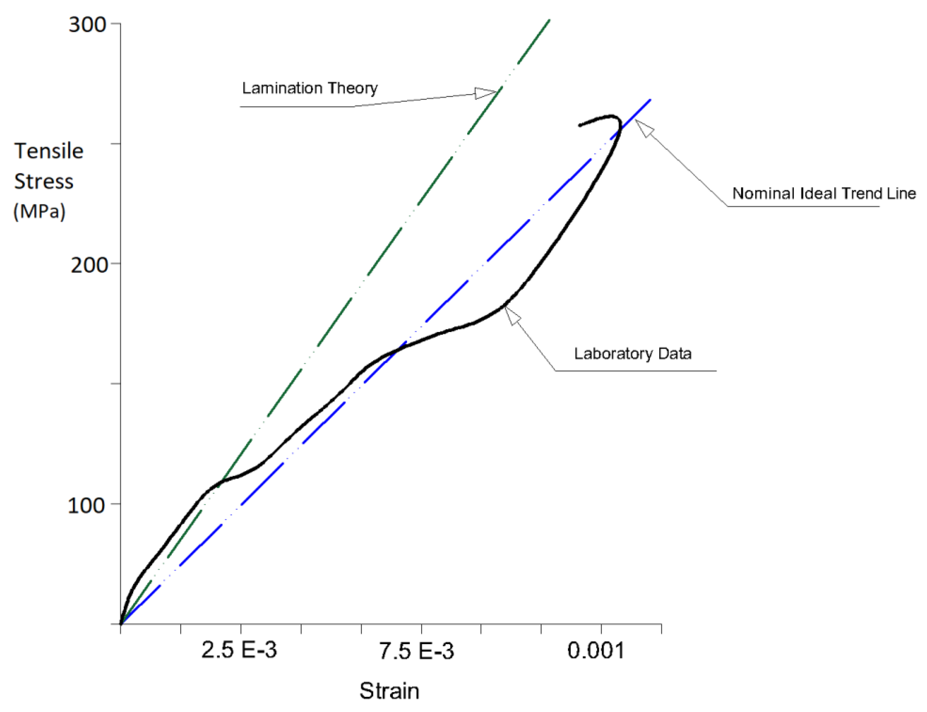
Material verification was controlled following the “coupon” testing methods and based on the lamination theory to calculate the maximum measured stiffness and strength capabilities of the GFRP members [
25]. The first step was to test a rectangular-shaped strip layer sample The actual strength measurement of the tube had an error at the very end of both fixing locations because of the stress concentrations around those regions [
26].
In the next procedure, steel tubes were used as a cover around the fiberglass tubes, along with resin to fill the empty voids. In this step, the GFRP coupons had a free (unfixed) length of 178 mm. After completion of the preparation stage, the GFRP samples at the fixed-end positions were tested under tension loading.
Figure 4 illustrates the results of the accumulated strain and stress following the laboratory tests.
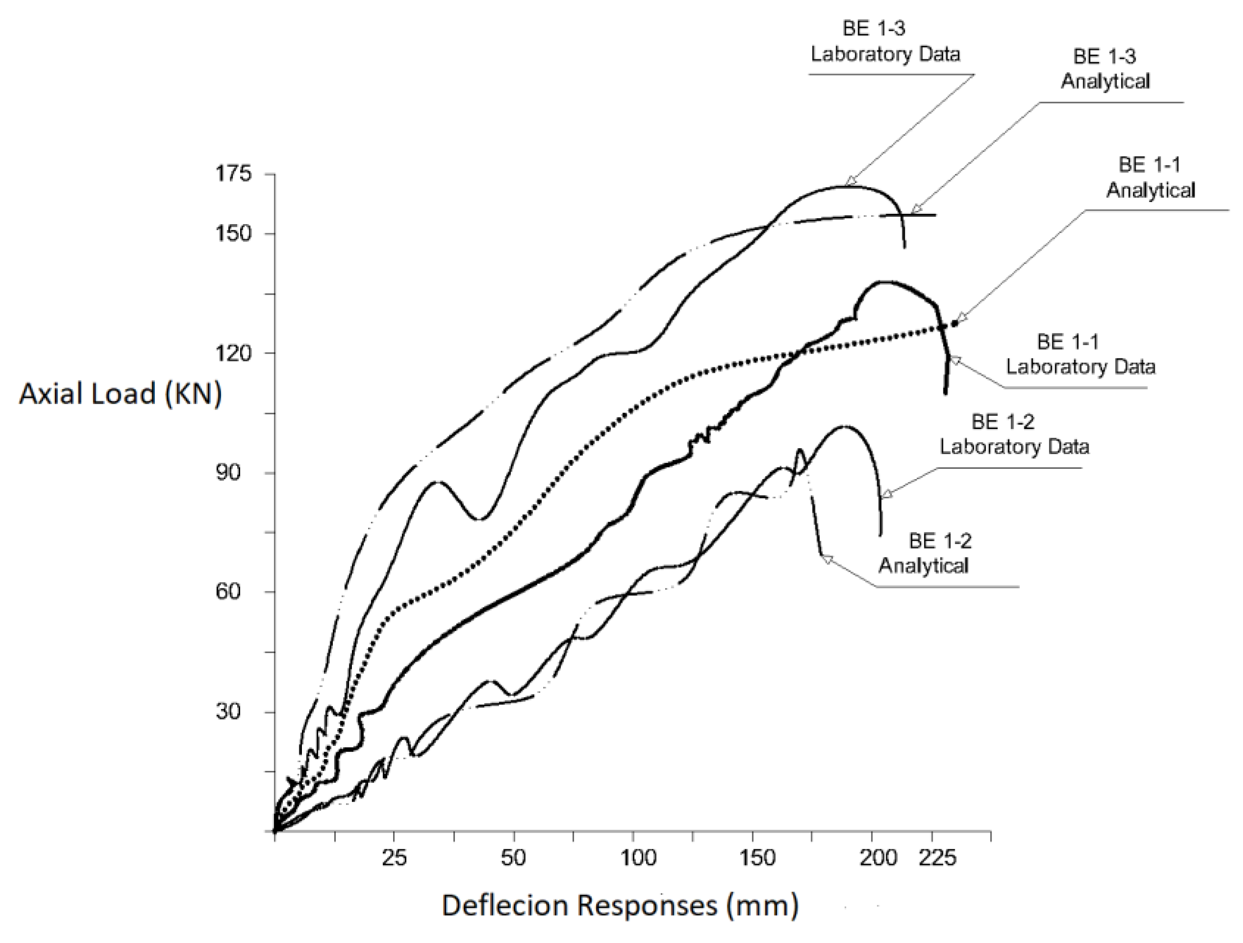
3.2. Response Evaluation of GFRP and Pre-Stressed Piles
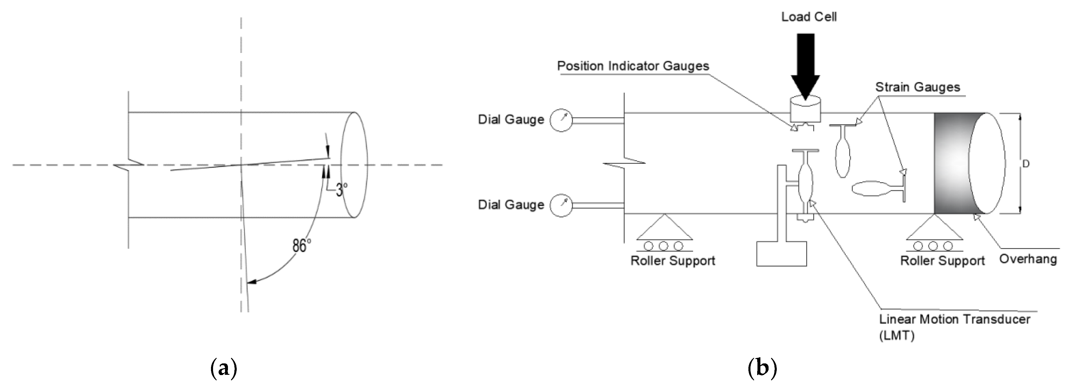
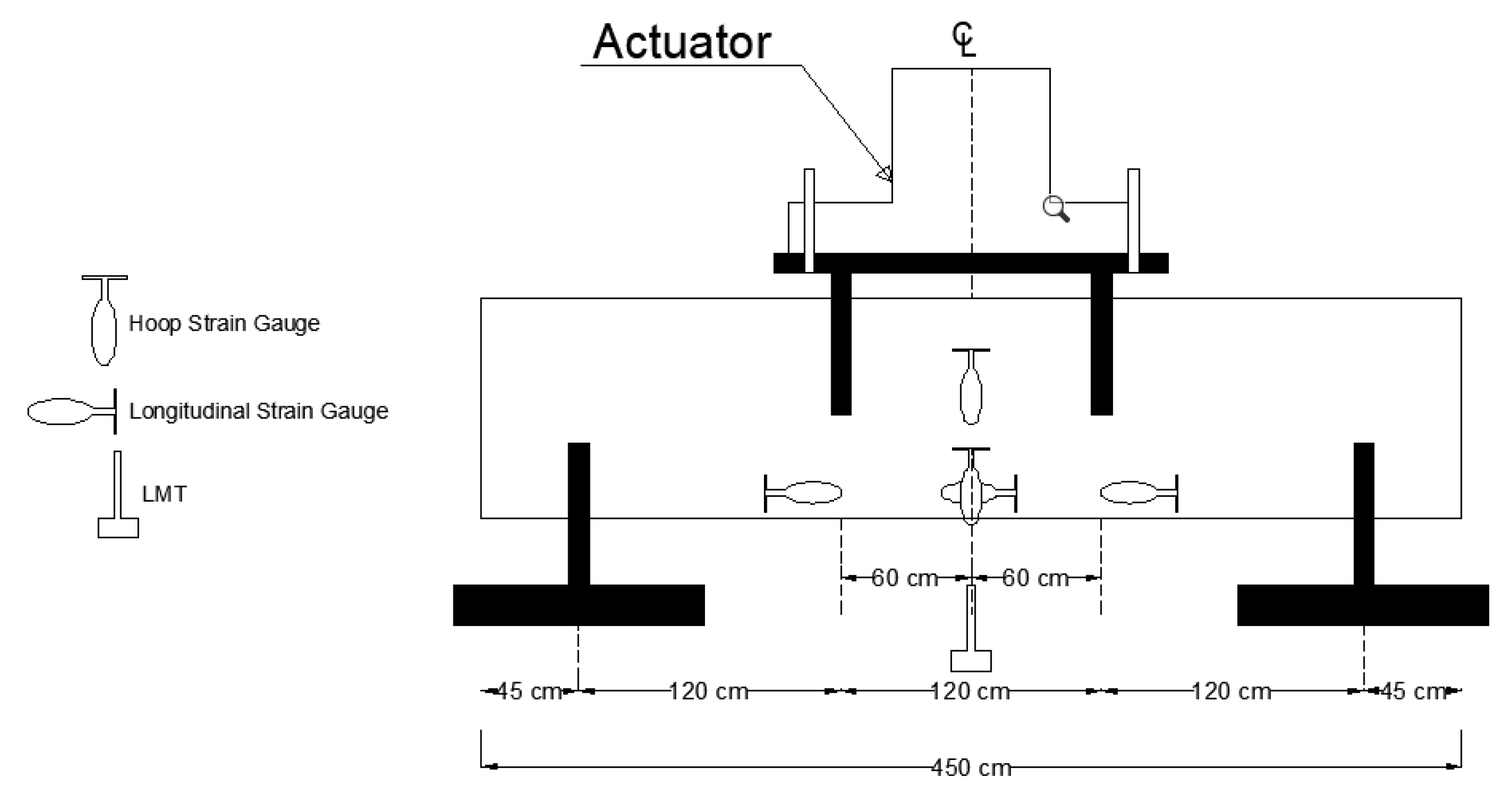
As mentioned before, the full-scale composite GFRP piles are instrumented using strain gauges to measure the deflection at the middle of the height of the eccentrically loaded column specimen. The strain gauges are also used to record the strains of the extreme fibers under tension and compression, based on the applied constant bending moments on the specimens. The relative slip range of the GFRP tube in contact with the recycled material is measured at both top and bottom of the columns. The load application is conducted by controlling strokes and appropriate care of cushion. The average rate of the loading was 1.5 mm/min.
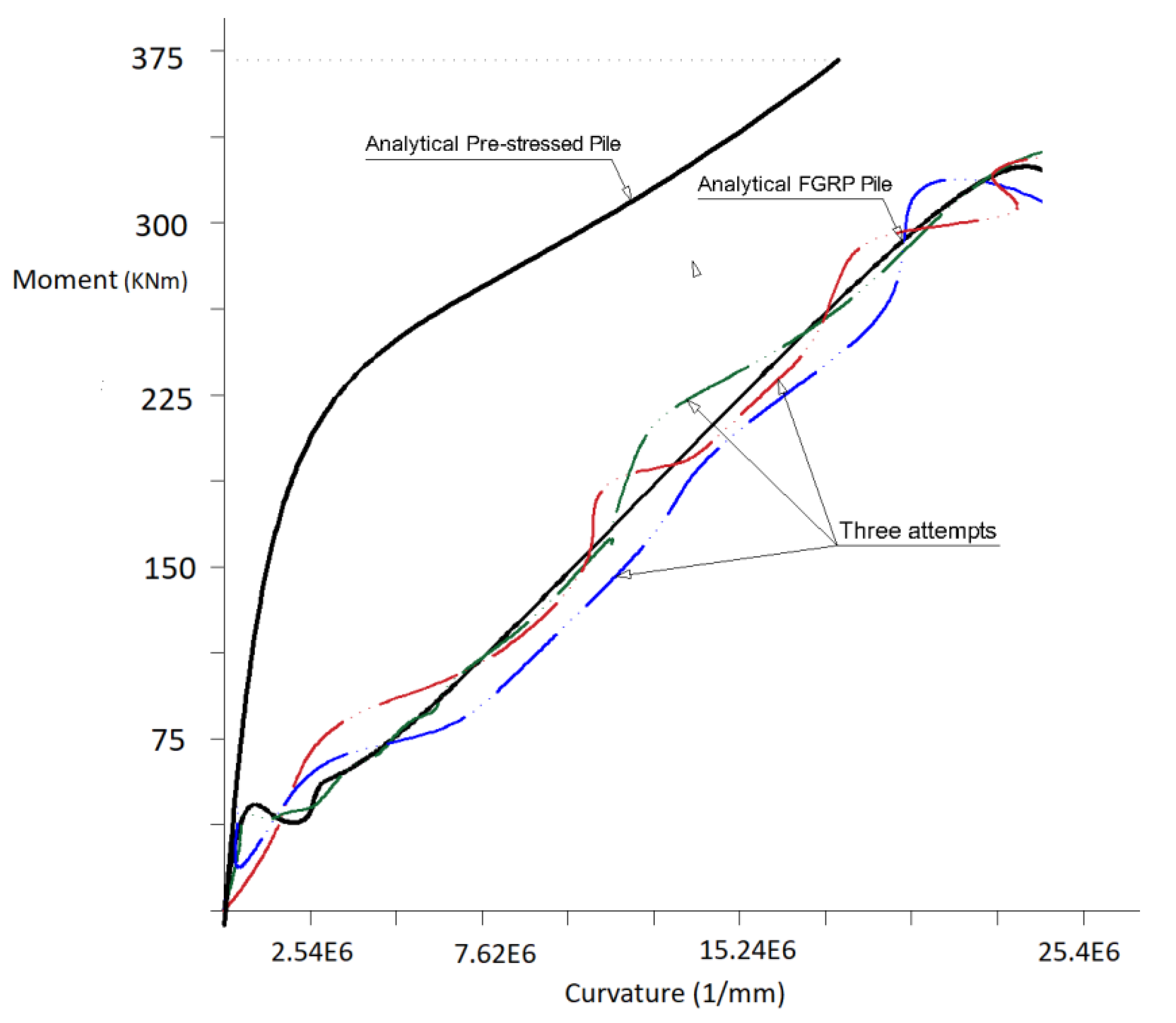
Figure 5 depicts the curvature-moment responses of the GFRP piles for the three geometrically similar eccentrically loaded column specimens. The crack moment, 43 kNm, is considerably small compared to the ultimate bending capacity of the specimens. An immediate drop in the bending capacity of the columns is recorded which is the result of the stroke control test after occurring the crack. An analytical comparison is conducted between the responses of the GFRP composite piles and pre-stressed piles filled with concrete. A prediction of curvature-moment response of the pre-stressed piles was calculated following the strain compatibility and equilibrium theory. Details of such an analytical model is available in the previous research studies [
27]. The Ramberg–Osgood equation was used to simulate the relationship between strain and strain responses of the pre-stressed strands. To simulate the nonlinear stress-strain behavior of the concrete in the pile reinforced with these pre-stressed steel material, a generalized expression model by Popovics [
28] is used. This predicted curvature-moment response of the pre-stressed concrete filled pile is shown in
Figure 5 for analytical comparison purposes. ACI 318M-19 Standard and AASHTO LRFD bridge design specification limited the ultimate useable compressive strain to 0.003, for the conventional plain concreter with limited ductility [
29,
30]. Following these standards, the same ultimate maximum strain of the concrete is used in the prediction of the responses of the pre-stressed piles filled with concrete material [
31].
The behavior of pile members in different loading scenarios is governed by type of the materials used for the construction of the piles. As a result, various composite materials considered in this research such as GFRP tubes, recycled and concrete materials provide the pile members with different strength and pile-deflection responses. Full-scale specimens provide this study with the opportunity to examine the response of such some composite pile members. Due to the various strengths of these materials, bridge design specifications recommend several types of design methods to deal with different reinforcement systems of pile members [
32].
Based on the responses, analyses of the pile members were performed by comparing moment-curvature graphs [
33]. First, the geometric characteristics of the GFRP filled with recycled materials were analyzed. A filled GFRP tube was stripped longitudinally and sampled. From the stress-strain data gleaned from the experimental test, which was semi-linear, the internal forces acting on the filled materials and the GFRP were evaluated by conducting a numerical analysis, as well as using regression on the resultant laboratory data, as is shown in
Figure 5. Second, in order to develop the moment-curvature diagram, the calculated internal forces were used to anticipate the internal moments in various locations following the estimated strain data. Three tests were conducted to compare the lateral responses of the GFRP piles.
As is shown in
Figure 5, when the internal moments reached the failure point, cracking occurred. At the cracking failure point, the moment capacity of the GFRP is decreased significantly following a non-linear response. Before the cracking, the stiffness capacity of the GFRP tubes and conventional pile were almost identical. Since the GFRP piles were filled with recycled materials, as a replacement of corrosive steel for reinforcement of the pile, the occurrence of the cracks will not affect the lifespan of the members in the long term because of eliminating the agent of the corrosion.
3.3. Field Results on GFRP Piles, Paramteric Study
As mentioned before, the use of full-scale test piles results in a more reliable outcome for analyzing the responses of the GFRP composite piles [
25,
34,
35]. The capacities of GFRP composite piles were measured under axial loading. Installed strain gauges and accelerometers measured the member’s displacements for both longitudinal and lateral loadings. The lateral deflection and displacement of the pile, as well as the axial strain and displacement responses of the piles, were measured and analyzed. For further illustration of the effect of GFRP tubes on the axial and bending capacities of the piles, a parametric study is presented as follows:
In this parametric research, the effect of different percentages of fibers on the axial and bending resistances of a test pile is investigated. Furthermore, variations of thickness of the GFRP composite tubes in both longitudinal and hoop directions on pile capacities are studied.
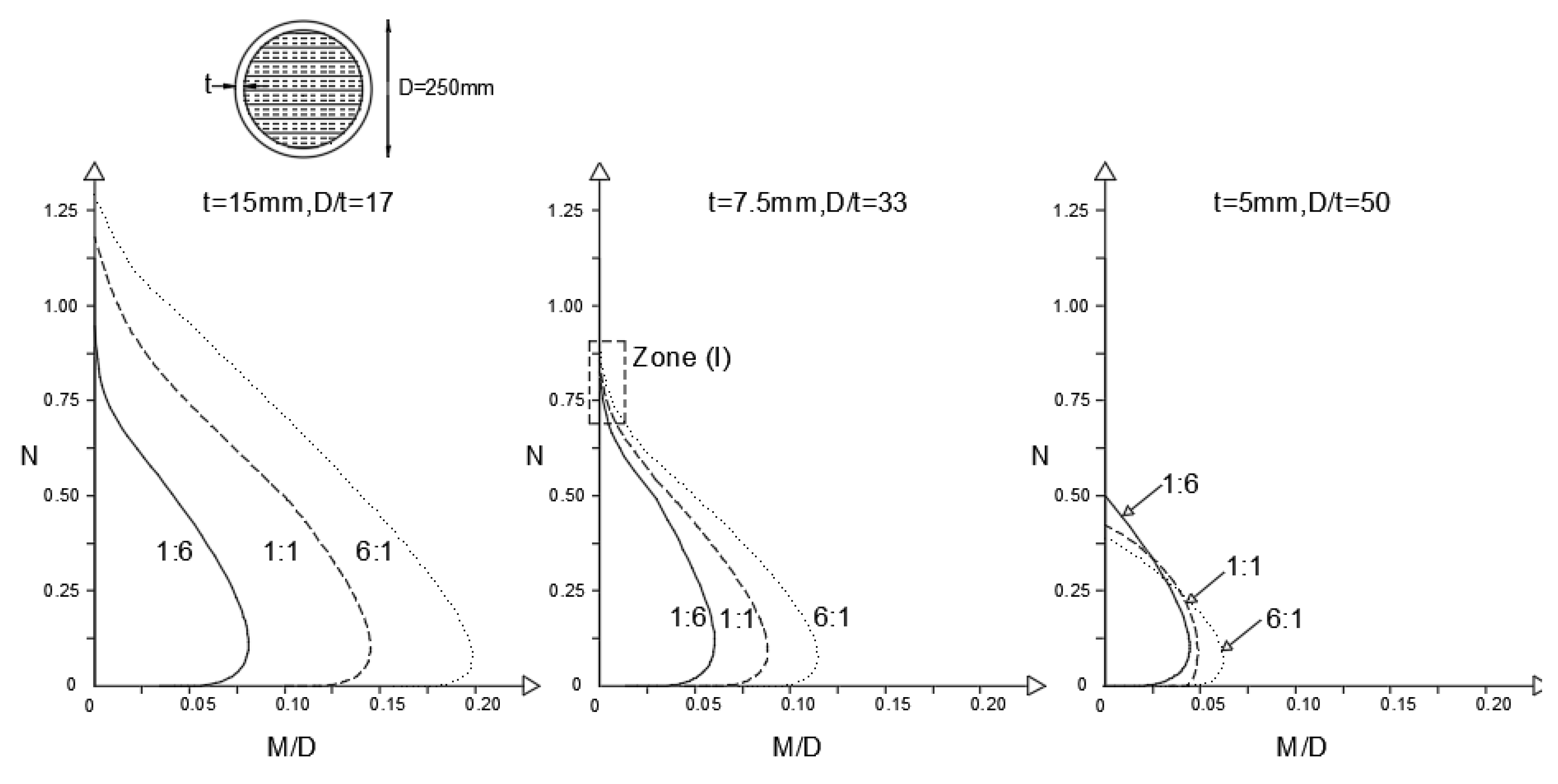
In this research, A GFRP composite tube with 250 inner diameters and filled with 30 MPa concrete is constructed using E-glass epoxy with the yield tensile strength of 27,500 psi based on the ASTM D638 specifications. Three arrangements for the laminate structure of the GFRP tubes were selected. The implemented percentages of GFRP fiber tubes in the longitudinal and hoop directions are varied using 1:6, 1:1 and 6:1 ratios. The 1:6 ratio indicates that 60% of the GFRP fibers are orientated in the hoop directions to increase the confinement capacity of the tubes under axial compression loading. The 6:1 GFRP laminate has 60% of these fibers orientated in the longitudinal direction to enhance the bending capacity of the composite tubes. The 1:1 ratio defines an equivalent distribution of fiber percentages in both hoop and longitudinal directions. Each of these ratios in the structures of the laminates is tested with wall thicknesses (t) 5, 7.5 and 15 mm, which are in respect equal to the 8%, 12% and 24%, as pile reinforcement ratios (4t/D). An analytical model is used to develop the interaction diagram [
25]. The combination of three different propionate percentages and three different thickness values, a total of 9 cases, were analyzed.
Figure 6 shows the axial-moment load interaction curve diagrams based on the thickness and fiber percentage variables. The axial compression and bending moment capacities of the tubes are presented based on the diameter of the pile D and compressive strength of the concrete
. In each diagram, three curves show the fiber proportionate ratios of the GFRP laminate structures based on the specified 4t/D ratios. The diagrams show that an improvement in longitudinal stiffness properties of the pile, for example from 1:6 to 6:1 fiber ratios, considerably adds to the moment capacity of the tubes in different thickness variations. In addition, increasing the GFRP tube thickness results in enhancing both axial and bending capacities. However, an increase in hoop stiffness, for instance from 6:1 to 1:6 fiber ratios is not necessarily increasing the pure axial capacity of the pile in compression for different thickness values. For example, for a 15 mm-thick GFRP tube, adding to the hoop stiffness is not increased the axial capacity of the pile. Although, for the tube with a thickness of 5 mm the increase of hoop stiffness results in enhancing the pure axial compression capacity. These outcomes for responses of the pile can be justified using the equations below [
25]. In the Equations (1)–(3),
is the ultimate axial capacity in interaction with the concrete
and the GFRP tube
. The cross-section area of the concrete is shown as
and
represents the confined compressive strength of the concrete.
is the effective modulus elasticity and
is the axial strain capacity of the tube at both ends.
The reduction of the hoop stiffness is shown by the decrease of the
in Equation (2). Therefore, the
is reduced in Equation (1).
is increased by increasing the longitudinal stiffness of the tube. For small variations in the thickness the rate of decrease of the
is more than the increasing rate of the
. As a result, the ultimate axial compression load capacity,
, is decreased. However, for large thickness values, the
becomes greater due to the increasing rate of the
The decline in the rate of hoop stiffness does not considerably affect the
for large thickness values. For the median values of the thicknesses, the reducing amount of the
happens at the same rate as the
increment and consequently, the change rate of the
is almost constant, as is presented in the Zone I of
Figure 6 for the GFRP tube with 7.5 mm thickness (D/t = 33). For the larger wall thicknesses, D/t within 33 and 17, interaction curves for various structures of GFRP tubes have no intersection. For the smaller thickness values, D/t between 33 and 50, the interaction curves have points of intersection.
These intersection points affect the effectiveness of the design procedure for various eccentricity values. For instance, as shown in
Figure 6, the curve attributed to the 6:1 ratio and with a relatively large eccentricity
, is tangent to the other two curves and acts as the envelope of the family curves.
Therefore, the 6:1 ratio is the most preferable fiber percentage for the design procedure compared to 1:6 and 1:1 ratios. On the other hand, the interaction curve related to the 1:6 ratio and with relatively small eccentricity is the envelope curve, compared to the other two curves. Therefore, the 1:6 is the most desired fiver proportion for the small eccentricity values. For the median eccentric values, , all the three curves attributed to 1:6, 1:1, and 6:1 have comparable efficiency to be selected for the design procedure. As a result, the ultimate axial and bending capacities of the piles are directed by the combination of GFRP fiber percentages and the tube thickness values for different ranges of eccentrics.
3.4. Significance of the Research
This study evaluated the response of full-scale piles in experimental analysis. The piles were reinforced with three different laminate structures of GFRP tubes. The tests were performed for pure bending, the combination of axial compression load and bending moment, along with the pure axial compression loading conditions. GFRP composite tubes were reinforced in both circumferential and longitudinal directions. The study investigated the use of GFRP reinforced piles as an alternative to the piles reinforced with FRP piles. Compared to the traditional reinforcement methods or use of FRP tubes, the application of the GFRP tubes is a more cost-effective practice in large-scale constructions such as bridge piers and has a considerable environmental impact. A parametric study is presented following the experimental tests for both axial compression and bending load applications.
4. Conclusions
Following the experimental data analysis, the use of glass-fiber-reinforced polymer has many benefits for the design and implementation of pile structures in large-scale construction projects, such as bridge structures. The use of piles reinforced with GFRP material in bridge design results in increasing the durability of these deep foundations and decreasing their construction costs. The allocated expenditure for recovering and repairing pile structures in both North America and Europe exceeds $1.5 billion dollars. Therefore, maintenance cost is a significant factor in the design of cost-effective structures. Using recycled materials as fillers in reinforced GFRP tubes decreases the total cost of production. In the past decade, using steel-reinforcement methods increased the cost of construction; however, developing structural piles with hybrid GFRP materials resulted in reducing the use of steel materials as reinforcing members. In addition, hybrid FRP materials, such as GFRP, enhance the anticipated lifespan of pile structures, even in such hazardous environments as oceans, where corrosion is one of the main concerns for the durability of these structures. Finally, these hybrid materials increase the anticipated strength capacity of the structures significantly.
The outcome of this research is based on a specific arrangement of GFRP layers, including their diameter, outer and inner thickness, and the degree of inclination from the longitudinal direction. Adjusting these specifications, as well as changing the material’s properties—such as EAxial, EHoop, and Poisson ratios—optimized the results. Based on the results from three full-scale samples, the deflection responses were linear in an axial loading condition before reaching the failure criteria. Since recycled material was used as filler inside the tubes, the long-term effect of cracking was negligible for high values of calculated strength, as well as under axial or lateral loadings. Some minor inconsistencies in such parameters as initial measurements or the calibration of samples could affect the outcomes.
Analyzing the internal forces of the GFRP tubes filled with recycled material showed the semi-linear behavior of the pile members, which resulted in increasing the total strength and ductility of the reinforced piles. The lateral responses of both the GFRP piles and pre-stressed piles showed comparable results, in that the effect of cracking under axial and lateral loadings was negligible.
A parametric study is conducted to investigate the effect of wall thickness and fiber percentages of the GFRP tubes on the axial and bending capacities of the piles. The structure of GFRP tubes, such as their thickness and ratios of the implemented GFRP in the pile considerably affects the axial-moment interaction curves of the piles. The T-2 type GFRP tube with higher hoop elastic modulus, 17.3 Gpa and relatively low Poisson’s ratio 0.085 has more confinement strength compared with T-1 and T-3 tubes with lower hoop modulus of elasticity values. Furthermore, the axial capacity of the tubes is changed due to higher GFRP fiber ratios in the hoop direction for small thickness values. However, the bending capacity of the tubes is governed by both thin and thick wall structures tubes for higher GFRP fiber ratios in the longitudinal direction. The increase rate of axial capacity for the GFRP with more thickness values tubes is higher in the longitudinal direction compared to the hoop direction. Furthermore, the effect of axial capacity is higher than the confinement capacity in tubes with lower thickness values. The required axial and bending resistance capacities of piles in different ranges of eccentricities can be met using the combination of tube wall thickness and GFRP fiber percentages following the curve interaction diagrams.
Further studies are recommended to investigate the developing of more reliable methods using full-scale test specimens with different laminate structures, various percentages of GFRP material along with using the tubes in different directions in both longitudinal and hoop directions. Furthermore, the effects of using other materials such as basalt fiber-reinforced polymer, as an alternative for GFRP material, could be investigated for more cost-effective design and implementation of piles.


