Article

Method to Increase the Accuracy of Large Crankshaft Geometry Measurements Using Counterweights to Minimize Elastic Deformations

by
Leszek Chybowski
*,
Krzysztof Nozdrzykowski
,
Zenon Grządziel
,
Andrzej Jakubowski
and
Wojciech Przetakiewicz
Faculty of Marine Engineering, Maritime University of Szczecin, ul. Willowa 2-4, 71-650 Szczecin, Poland
*
Author to whom correspondence should be addressed.
Appl. Sci. 2020, 10(14), 4722; https://doi.org/10.3390/app10144722
Submission received: 26 May 2020 / Revised: 30 June 2020 / Accepted: 7 July 2020 / Published: 9 July 2020
(This article belongs to the Special Issue Ship Energy Systems)

Abstract

:
Large crankshafts are highly susceptible to flexural deformation that causes them to undergo elastic deformation as they revolve, resulting in incorrect geometric measurements. Additional structural elements (counterweights) are used to stabilize the forces at the supports that fix the shaft during measurements. This article describes the use of temporary counterweights during measurements and presents the specifications of the measurement system and method. The effect of the proposed solution on the elastic deflection of a shaft was simulated with FEA, which showed that the solution provides constant reaction forces and ensures nearly zero deflection at the supported main journals of a shaft during its rotation (during its geometry measurement). The article also presents an example of a design solution for a single counterweight.

1. Introduction

The geometries of small machine components are easily measured because they are very common in mechanical engineering, and the relevant measurement instruments are available [1,2]. However, a ship’s engine room primarily contains equipment with medium and large components [3,4] that are heavy and large, and display low, variable rigidity that makes them highly susceptible to flexural deformation. This group of machine parts includes crankshafts, camshafts, straight shafts, and stage shafts that are part of line shafting [5]. We consider a crankshaft to be large where the length-to-diameter ratio (L/d) is greater than 12 ÷ 15, whereas the shape factor αk determining the nature of cross-sectional changes may take on significant values αk ˃ 1 [6].
Ship engine crankshafts are primarily used in diesel engines (reciprocating internal combustion engines), but they are also used in other types of haulage and transport (rail, road), agriculture, mining, and industrial construction.
When characterizing large crankshafts, the manufacturing technology must be considered because it is closely linked with the construction and shape. Crankshafts are formed by machining, resulting in complex shapes with low rigidity. Additionally, their manufacture requires high geometric precision, causing crankshafts to account for an estimated 20–25% of the total engine cost [7,8]. Crankshaft manufacturing precision largely determines whether a crank-and-piston system will function correctly and, consequently, the entire working machine’s reliability, safety, and operating costs [9,10,11].
Manufacturers impose strict requirements on the machine components that mate with the non-rigid thin-walled multilayer bearing liners used in modern marine engines. For this reason, modern manufacturing processes require continuous quality control for manufactured crankshafts [12,13,14]. A complete assessment of the geometric condition of a product to reflect its actual state can only be ensured using suitable measurement methods and techniques, and they should enable metrological and instrument accuracy within the specified tolerances [15].

2. Crankshaft Geometry Measuring Methods

While reviewing and categorizing the applied measurement methods and techniques, two basic criteria should be highlighted. The first criterion involves the measurement conditions in industrial settings, where a manufacturer typically has specialized, expensive measuring equipment and instruments [16]. Due to their high cost, these are not used in shipyards or overhaul plants, which have limited measurement capabilities.
The second criterion involves dimensions, which are closely related to the weight and design of a shaft. As highlighted in many studies [17,18,19], the overall dimensions of a shaft are the basic criteria used to classify shafts and are often a decisive factor when choosing measuring methods and instrumentation. Table 1 presents an overview of crankshaft measurement techniques and methods, categorized by shaft dimensions and measurement conditions, which include the way the shaft is fixed, the plane in which the measured shaft is positioned, the measurement system parameters, and the applied support.
According to this classification, there are non-reference methods that measure the radius and reference methods that evaluate the position of points of a profile being measured relative to one or more other points of that profile. However, to advance this measurement technology, we must focus on another group of methods, i.e., measurements based on an object’s image, such as scanning and photometry [20,21,22]. Such a system uses two cameras and the projection unit operates according to the triple scan principle. During the measurement, the surface of the object is analyzed and recorded by the cameras. It is a complete, automatic, optical 3D measuring machine used by manufacturers to control the quality of produced parts.
Reference measurements performed in a device with centers are most commonly used in the small shafts in high-speed engines (Figure 1). Taking into account the load capacity of fixed centers, measurement is possible only if center holes were previously made in the measured shaft, which must be small and low weight. These types of advanced measuring systems are coupled with a computer and allow the roundness profile to be digitally measured [23,24].
This total measurement error of this method depends on the manufacturing precision and type of center holes, the manufacturing precision of the center device, the type of sensor, and the method and accuracy of results analysis. Such solutions are often used for workshop measurement techniques. The shaft axis is horizontal and in the simplest solution can be kept in this position using a universal center device and a sensor set in a tripod.
For the abovementioned group of shafts and crankshafts in medium-speed engines, non-reference measurement methods are performed using a device with a rotary table [25] or rotating spindle [26]. The operation principle of these two systems is shown in Figure 2.
An example of such a device is shown in Figure 3. Non-reference measurements of such shafts can be performed on specially adapted measurement instruments or machines offered by well-known measuring equipment or instrumentation manufacturers.
In most commercially available measurement machines, shaft axes are positioned vertically during measurements to enable a comprehensive and quick assessment of the geometric condition of a shaft. In these instruments, the sensor’s measuring tip moves as the radius of the object being measured changes. The processed and amplified signal allows the measured profile to be recorded as a graph to determine the profile evaluation parameters. Instruments designed for non-reference measurement methods provide highly accurate measurements. The use of computers in modern non-referenced measurement instruments makes it possible to eliminate many errors, especially systematic errors [27]. Non-reference measurements of large shafts can also be performed on coordinate measuring machines [28,29,30,31], and optical scanners [32,33,34] are increasingly used, examples of which are shown in Figure 4.
Measuring instruments or machines performing non-reference measurements are accurate but are mainly used in laboratories because they require specific measuring conditions, including the accurate, time-consuming centering and aligning of measured items at ambient conditions (temperature, pressure). An additional limitation of these instruments and machines is their high cost, which prevents them from being used to produce small batches of units or in overhaul conditions. The use of these machines will not eliminate the basic difficulties in fixing and supporting large and flaccid components.
Attempts have also recently been made to use modern measurement techniques for large crankshafts. For example, the Tritop photometric mobile system and a system based on the Atos Trident III optical scanner was used to pre-assess the suitability of a semi-finished product to machine a 40-tonne forged crankshaft with a length of 13 m [35]; however, the use of these techniques is very limited due to their low accuracy. The restriction also applies to the use of other mobile shaft measuring devices (such as measuring arms), which unfortunately have significant uncertainty in their measurements. Taking these restrictions and the recommended accuracy requirements for the measuring equipment into account, this type of device may be used to measure the overall shaft dimensions.
By analyzing the measurement techniques for medium and large crankshafts in the conditions present in repair docks and workshops, the most common reference measurement methods are used to locate the shaft in vee blocks. Medium shafts are most often fixed in four vee blocks arranged on a bench plate, as shown in Figure 5.
Large crankshafts are fixed with multiple vee blocks, and measurements are performed on a specially adapted bench equipped with fixed rigid supports and vee block heads. These supports are anchored to the base with set screws, and the supports can be repositioned by moving them along the main guides of a bed and adapting them to main journals, depending on the shaft design.
The shaft geometry is assessed using a series of separate measurements [7], most of which are performed with multi-purpose measuring equipment [36]. The crank web deformation measurements (Figure 6a) are both the basic and final criteria for evaluating the geometry (apart from measurements of linear and angular dimensions, radial, and axial run-out of main journals, the parallelism of main and crank journals, and surface roughness measurements). This is commonly referred to as a springing measurement and is performed using a displacement sensor installed in a special holder [7,37]. Both the sensor’s probe stylus and the holder are equipped with centers, into which the instrument is seated in holes that crankshaft manufacturers pre-drill into the inner faces of individual crank webs. Springing measurements are performed in the vertical and horizontal planes, as the difference between the sensor readings in the two opposite outermost positions of the cranks while the shaft rotates. These extreme positions of the vertical plane are top dead center (TDC) and bottom dead center (BDC), respectively. In the horizontal plane, these positions are called the starboard side (SS) and the port side (PS).
Assessing a shaft’s geometric condition is thus based on indirect measurements. Springing measurements are the final criterion for assessing the shaft geometry, since it is not possible to directly measure journal axes’ shape deviations and positional deviations. When the shaft is supported on several fixed, rigid vee block supports, it is difficult to eliminate a shaft’s elastic deformation due to pre-deflections and geometric deviations. This results in geometric deviations that are conjugated with and interact with elastic deformations, making them virtually impossible to eliminate. In addition, conventional springing measurements suffer from a lack of permanent measurement means. In this case [7], the results are interpreted by assuming that the crank web deformations are symmetrical with respect to the main axis of a crank (Figure 6b), which is not always the actual case [38,39].
This assumption follows from the principle of measurement, as the sensor measures the total deformation of crank webs, which often results in the misinterpretation of measurement results. However, contrary to the previous remarks, this type of measurement is now commonly used to verify and assess shaft geometries, and crankshaft manufacturers use it at individual stages of interoperational inspection and in the final assessment of the shaft geometry. Repair shops and docks also use this type of assessment under operating conditions to measure the accuracy of the shaft bearing in the engine body. There are a number of scientific papers tackling the issues of appropriate bearing alignment [40] and identification of dynamic bearing parameters [41,42,43]. In our paper, we tackle quasi-static conditions during geometry measurement.
The procedures for measuring large crankshafts show significant limitations concerning the comprehensive measurement of geometric deviations, especially those in the shape and the position of axes [5]. These procedures are based on outdated measurement techniques, whose accuracy has not been adjusted to match the increasing manufacturing precision expected of modern crankshafts. Significant progress has been made in this type of measurement, as the discussion of current issues was narrowed to measuring deviations and shape profiles of cylindrical surfaces of shafts (main journals, crank journals). Particularly worth noting are the effects of works carried out at the Kielce University of Technology. This resulted in the development and implementation of an industrial-grade measuring system using a MUK 25-600 head and SAJD software to measure deviations and roundness profiles of large cylindrical machinery components (Figure 7) [23].
Measurements are performed by the reference method when using this system. The MUK 25-600 head, equipped with an induction displacement sensor, is mounted directly on a cylindrical surface. The measuring head is connected to a computer with SAJD software, which transforms the measured profile into an actual transformed profile. This approach enables the reference method to be applied to the measurements performed by non-reference methods, i.e., those whose results can be obtained using precise but expensive measuring machines. The resulting, digitized actual profile can be presented in either a polar or Cartesian coordinate system. The profile is defined by nf harmonics (nf2 ÷ 15⟩ or nf2 ÷ 50⟩) and includes some surface waviness components. The basic version of the program allows the roundness profile to be assessed using roundness deviation ΔZ and the amplitude of the largest harmonic Ck to present the profile as an amplitude spectrum. The extended version of the software enables a complete assessment of the roundness profile in accordance with the ISO standard by selecting the appropriate filter and reference circle and by determining any profile assessment parameter.
An important advantage of this system is that measurements can be performed directly on a production line, and the measured object does not need to be dismantled. Similar features are observed in various design solutions of measuring heads equipped with multi-contact self-aligning vee blocks cooperating with one or more dial sensors. The mathematical tools developed for this type of measuring instruments enable the selection of the number, shape, and positions of supports and sensors for specific measuring tasks with the required accuracy.
However, as previously highlighted, it is only possible to assess the deviations and shape profiles which, from the perspective of performing a comprehensive assessment of journal geometry, only provides partial control of the measurement accuracy. The measurement of axle position deviation remains difficult.
The presented review of the state of knowledge has shown the insufficiency of crankshaft measurement techniques, in particular those used for medium and large crankshafts for low-speed engines. However, these methods can still be used, as the elastic susceptibility of such flaccid, large components facilitates the shaft alignment on supports. This means that by improving the accuracy and measurement methods, better operational parameters of shafts, such as durability, service life, and reliability, can be achieved.
Currently, measurements of large crankshafts require the shaft to be supported on several fixed, rigid vee blocks. Simulation results have shown that there are significant deformations, and it is not possible to eliminate shaft deflections and elastic deformations when only some main shaft journals are supported, which is common in measurements under manufacturing conditions in overhaul workshops.
Many studies have shown that to correctly assess the geometrical condition of a shaft, it is necessary to provide appropriate measurement conditions, including the use of a support to eliminate deflections and, consequently, elastic deformations of the crankshaft caused by its self-weight and by its geometric deviations.
Therefore, to ensure correct measurement conditions, all main journals must be supported by a set of supports to compensate for these deflections and elastic deformations under their own weight, as well as those caused by geometric deviations of the shaft [38]. The reaction forces where the support heads and main journal contact should guarantee zero deflections at journals when rotating the supported shaft by any angle. Thus, to satisfy this criterion, the reaction forces should only vary at the successive supports bearing the individual main journals, also depending on the shaft rotation angle at the supports.
The distribution of reaction forces for crankshafts of different designs were analyzed, and it showed that, for most shafts, in the round-angle shaft rotation, the distribution of zero-deflection forces at individual journals formed a symmetrically deformed 8-shaped ellipse in the polar coordinate system [39], similar to a cosine function in the Cartesian coordinate system.
In these cases, providing shaft support with variable reaction forces requires a complex support force control system in which the reaction forces where the supports contact the main journals of the shaft, depending on its angular position, are continuously adjusted by precision current-controlled valves in a force sensor feedback system [5]. The force sensors measure the actual reaction forces at the contact between the support heads and main journals. The reaction forces are then compared with the pre-set forces (obtained beforehand from strength FEM-calculation program) to ensure zero deflection at journals. The parameters for simulation are a Tetra-type element, 242,207 nodes, and 145,639 elements. The analyzed parameters for elements are force and stress. The analyzed parameters for nodes are displacement, applied load (gravity), constraint force, and contact.
If the set forces do not match the measured forces, the latter are corrected by changing the pressure in the precision-controlled valve support cylinders until the reaction forces are equal to the set forces [5]. The vibration of the crankshaft [44,45] during the measurement was not analyzed as the conditions are quasi-static. Due to the character of reaction forces, we did not discuss either any vibration model or any issues of structural dynamics of reciprocating engines [46,47,48,49,50]. The entire adjustment process is controlled by a computer-based monitoring application.
This article presents a “reverse” approach, which is a novelty in crankshaft geometry measurements, i.e., instead of changing the reaction forces with controlled-cylinder supports, we propose placing the shaft on rigid supports and modifying elastic deflections of the shaft by temporarily attaching counterweights to it for the duration of geometry measurements.

3. Materials and Methods

As previously highlighted, the discussed control system is complex, making it quite expensive. Thus, testing was undertaken to find a solution that would stabilize the reaction forces to simplify the support control system by changing the shaft structure to identify a design that distributes the reaction force over individual main journals with small variations. First, we used a specific shaft design presented in Figure 8, where the center of gravity of the crank-web and journal system were located in the axis of the shaft, which ensured that the calculated reaction forces at individual main journals were constant.
Based on simulation results, a shaft was engineered so that its center of gravity was located in the main axis of the shaft to ensure minimal changes in the reaction forces at individual main journals during shaft rotation. The shaft’s design was modified compared with the nominal design by attaching counterweights to crank webs opposite them. Moments of inertia of counterweights were not considered because the measurements were quasi-static. The counterweight masses were calculated from the requirement for the equilibrium of torques of gravity forces from all masses (crank webs, crankpins, additional counterweight masses) with respect to the shaft rotation axis. In practice, the solution required the determination of counterweight parameters, which, after being applied to the shaft design, caused the counterweights to balance the torques of the cranks. Three counterweight shapes (Figure 9) were considered.
These counterweight shapes made it possible to distribute their masses and position their centers of gravity to obtain the torque of counterweight gravity forces that balanced the moment of the gravity forces of cranks. Solution “c” was chosen as the most advantageous because of its slenderness and compactness and manufacture and assembly technology. An analysis was performed for the shaft of a ship’s Buckau Wolf R8 DV136 main engine, the model of which is shown in Figure 10.
The crankshaft is 3630-mm long, weighs 9360 N, and is fitted with ten main journals, each 149 mm in diameter. It also has eight crankpins, each 114 mm in diameter. The shaft model was engineered with a design that was modified compared with the nominal one in Figure 11.
Each crank was equipped with a pair of counterweights to compensate for the elastic deflection of the shaft rotation during measurements. The measurement procedure using the proposed solution should follow the activity diagram in Figure 12.
According to the assumptions, the procedure consists of the following steps:
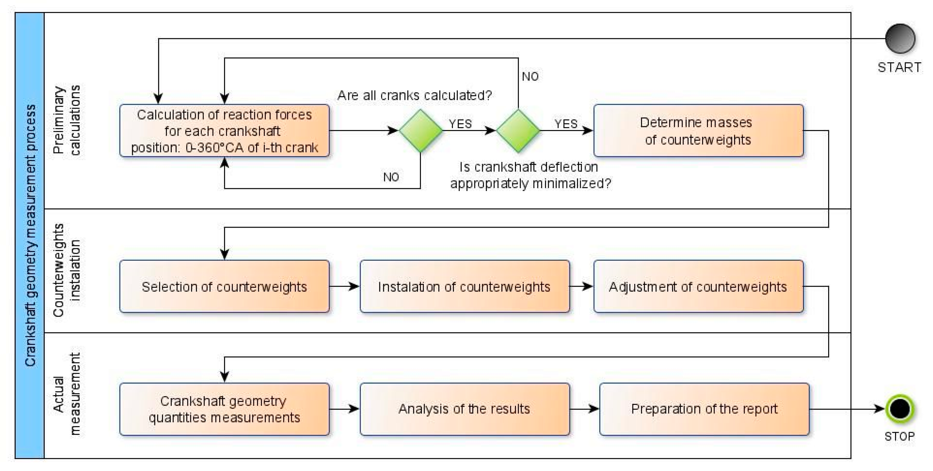
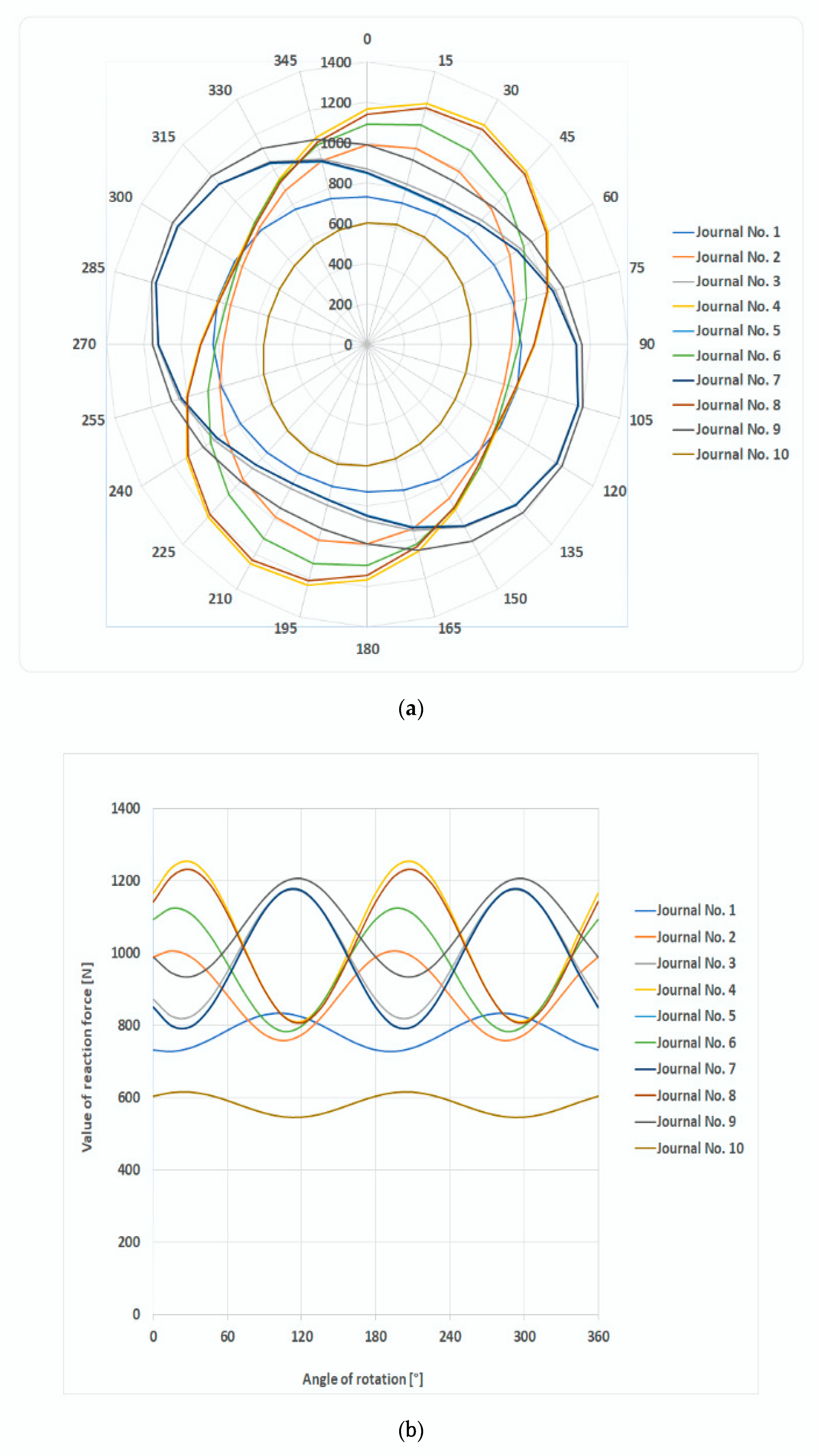
  • Calculating the reaction forces at the supports of the analyzed shaft for specified increments of the rotation angle from 0–360°, e.g., every 15 degrees.
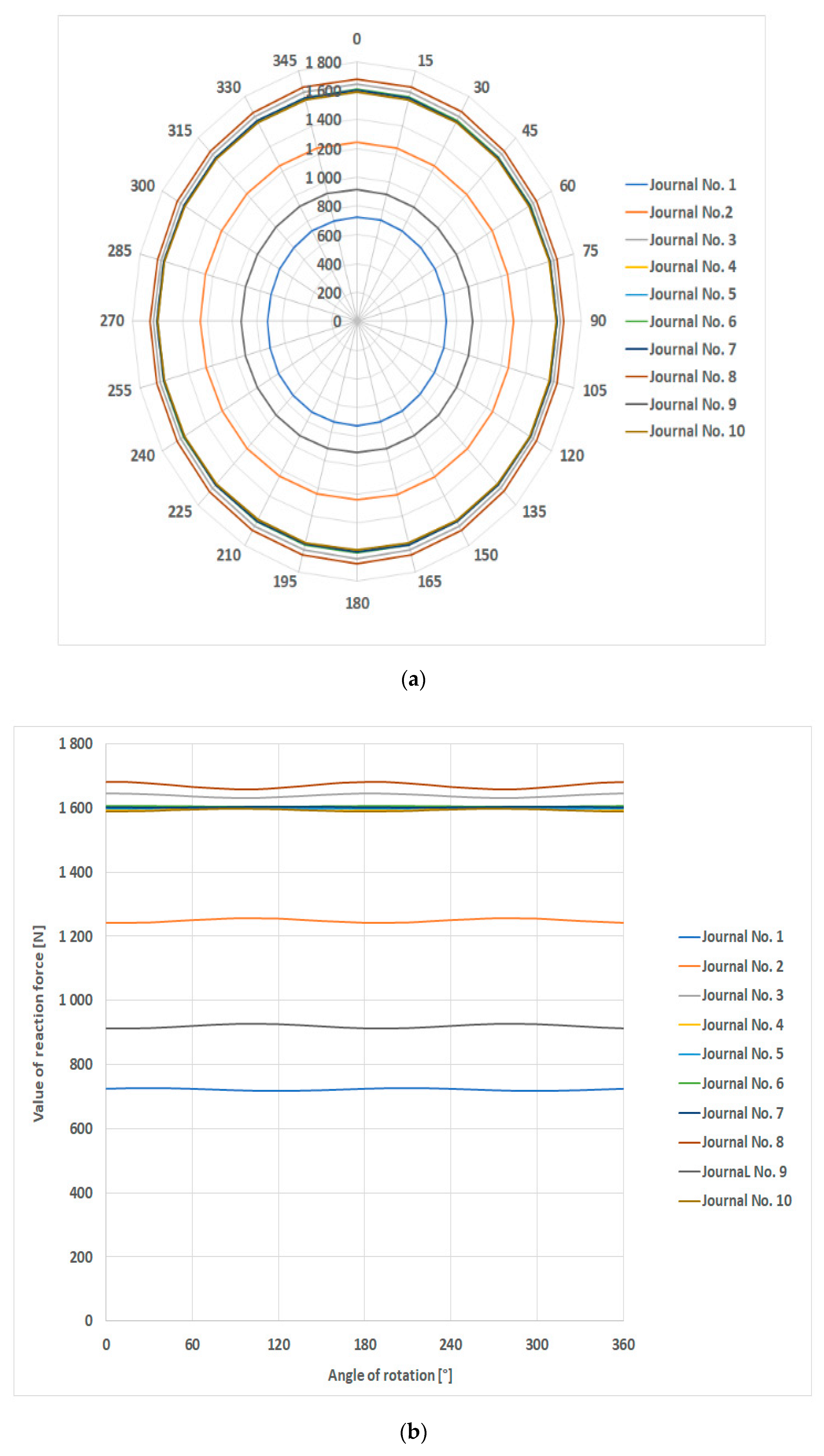
  • Determining balancing masses, the locations of their centers of gravity, and the position of masses on the crank to obtain the minimum changes in reaction forces for a full shaft rotation (as shown in the example). In practice, a reaction force deviation equal to approx. 0.1–0.5% prevents a shaft’s elastic deformation from affecting the accuracy of profile measurements.
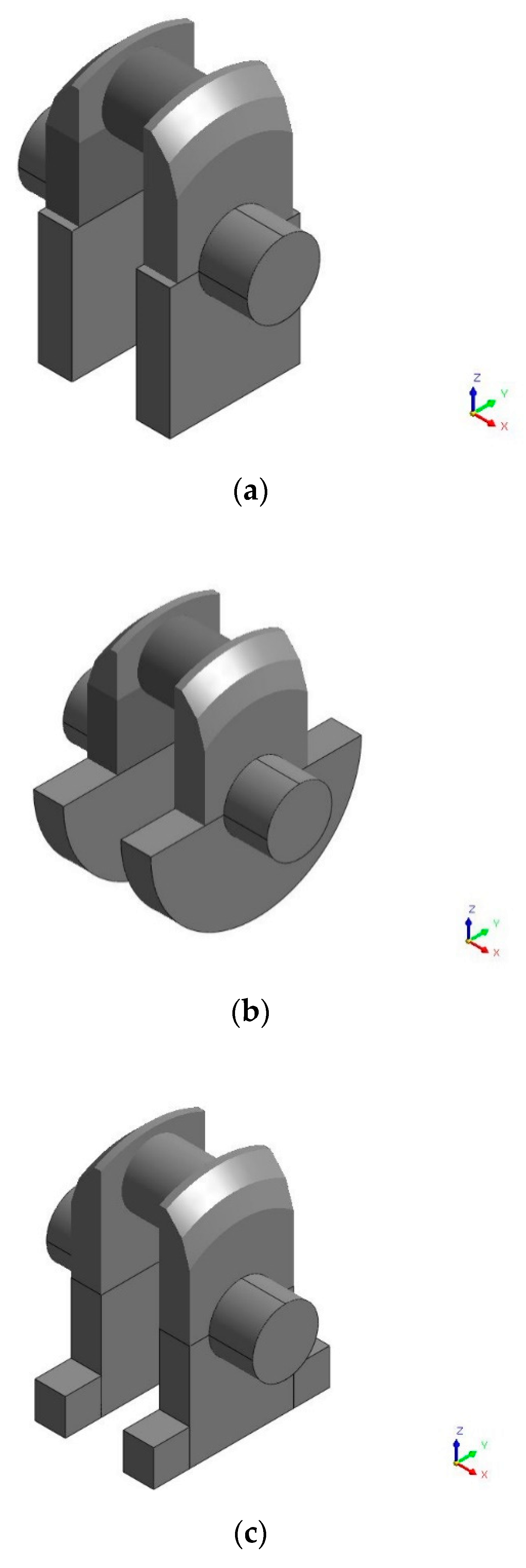
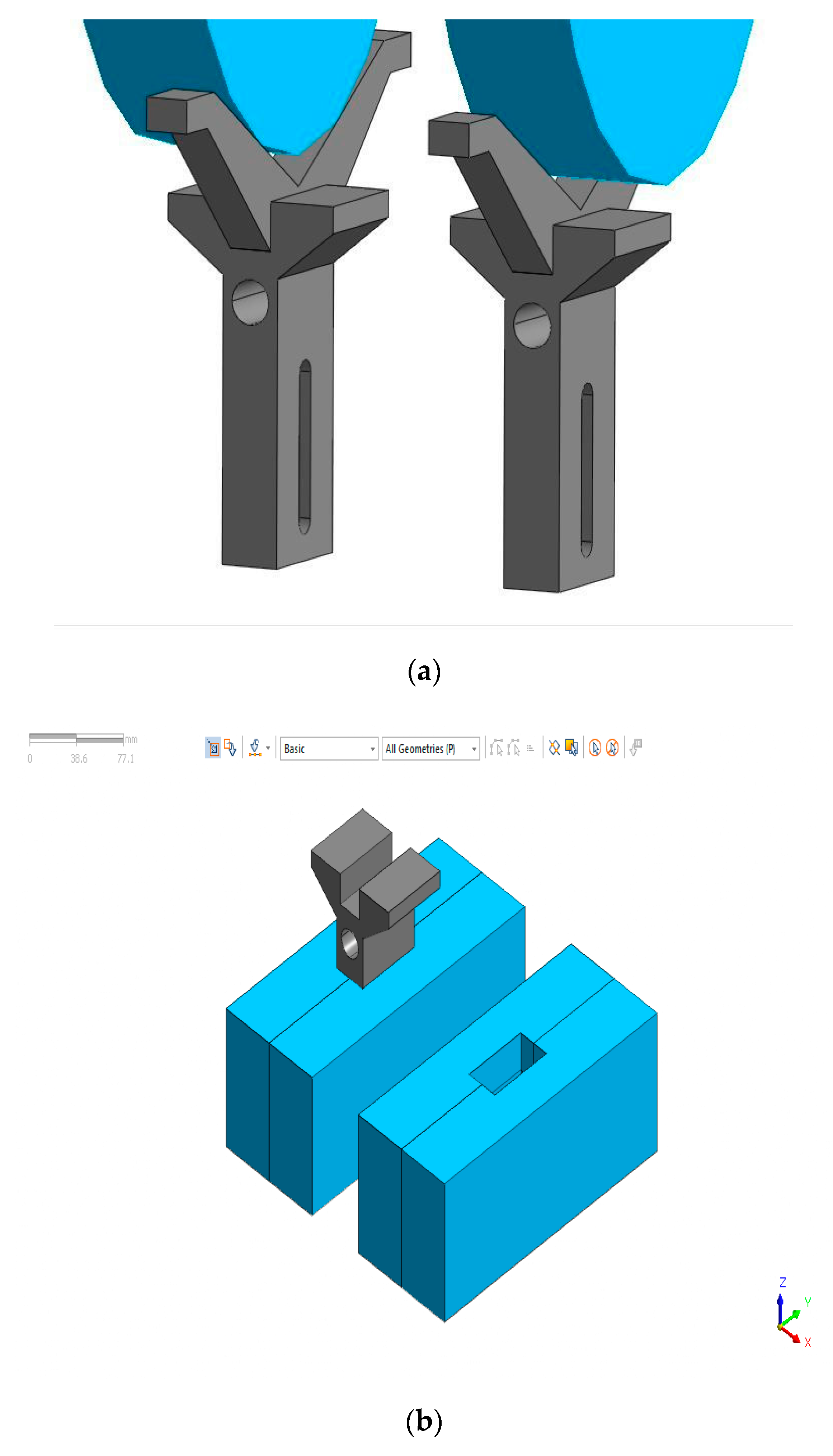
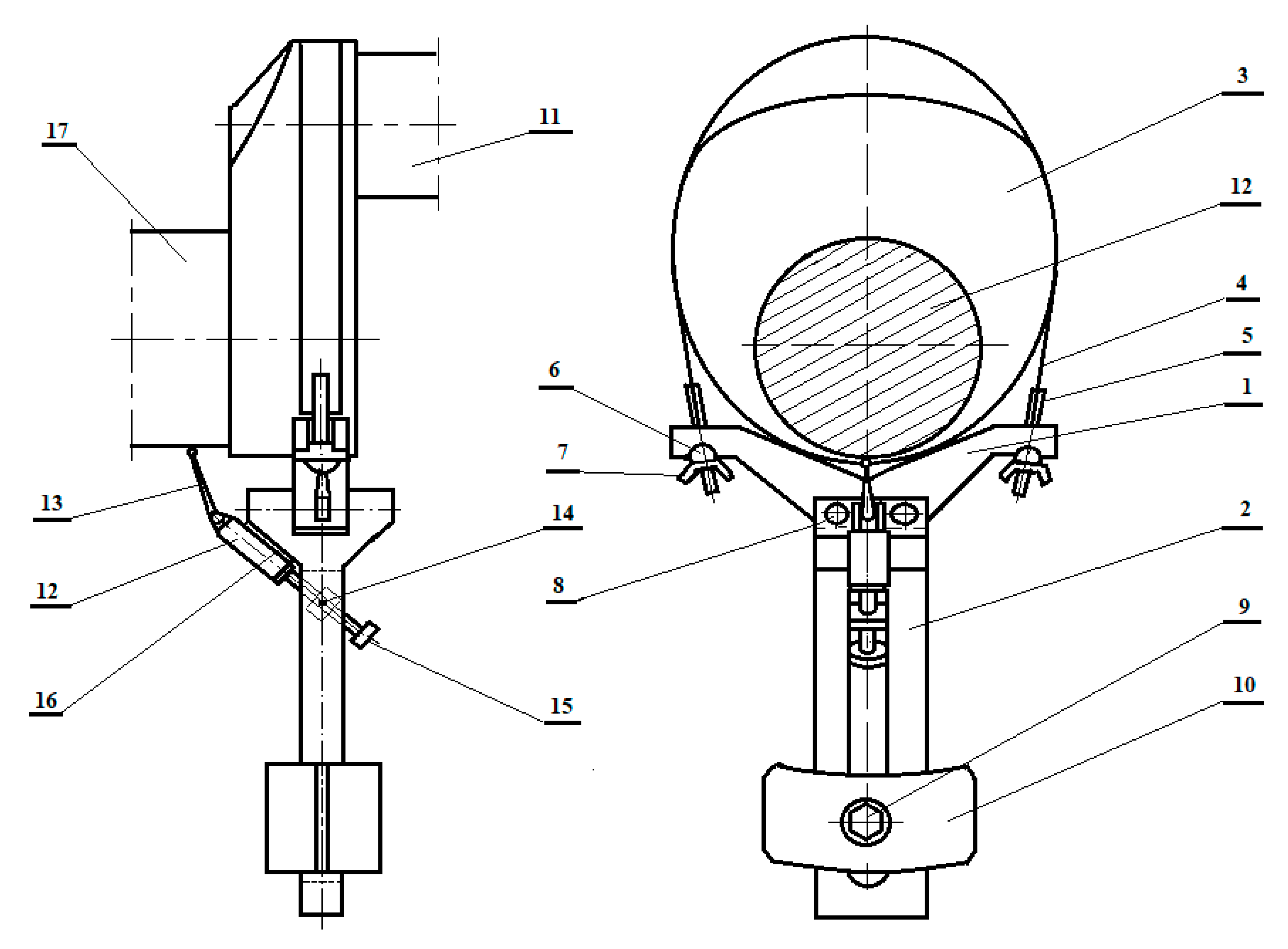
  • Fitting the crank with a correction device with weights that correspond to the calculated reaction forces. The device should be installed in the crank’s plane of symmetry, perpendicular to the longitudinal axis of the crankshaft. The weight must be located symmetrically, opposite the crankpin, for which the indications of the correction device’s displacement sensor may be helpful.
  • Adjusting weights so that the center of gravity of the device with the weights is as recommended in point 2. The center of gravity must also be located in the plane containing the axis of symmetry of the main journal and the crankpin, for the crank in which the device is installed.
  • Implementing steps 3 and 4 for all crank webs.
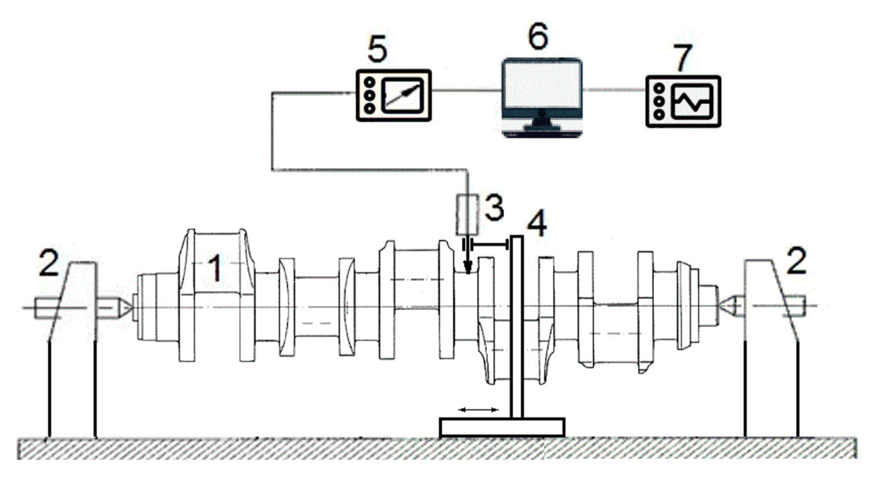
  • Properly measuring the geometry of the main journal by fully rotating the shaft, while gauging it with a dial displacement sensor or an electronic readout displacement sensor.
  • Repeating step 6 for all main journals.
  • Summarizing the results and drawing conclusions about the geometry of the shaft.
The following section presents the results of the calculations to confirm that this procedure minimizes the shaft deformation during measurements.

4. Results and Discussion

4.1. Calculations Confirming the Proposed Concept

Table 2 and Figure 13 show the results of calculations of the reaction forces that ensure nearly zero deflection at the main journals for the crankshaft of the analyzed engine.
The calculated reaction forces for the modified crankshaft design in a vessel’s main propulsion medium-speed engine, are presented in tabular (Table 3) and graphic form (Figure 14).
The calculation results showed that deflections could be minimized by applying temporary counterweights. In the polar coordinates, the deformed ellipses depicting the variability of reaction forces (Figure 13a) were nearly circular (Figure 14a), while in the Cartesian coordinates, sinusoids (Figure 14b) were formed as constant function curves.

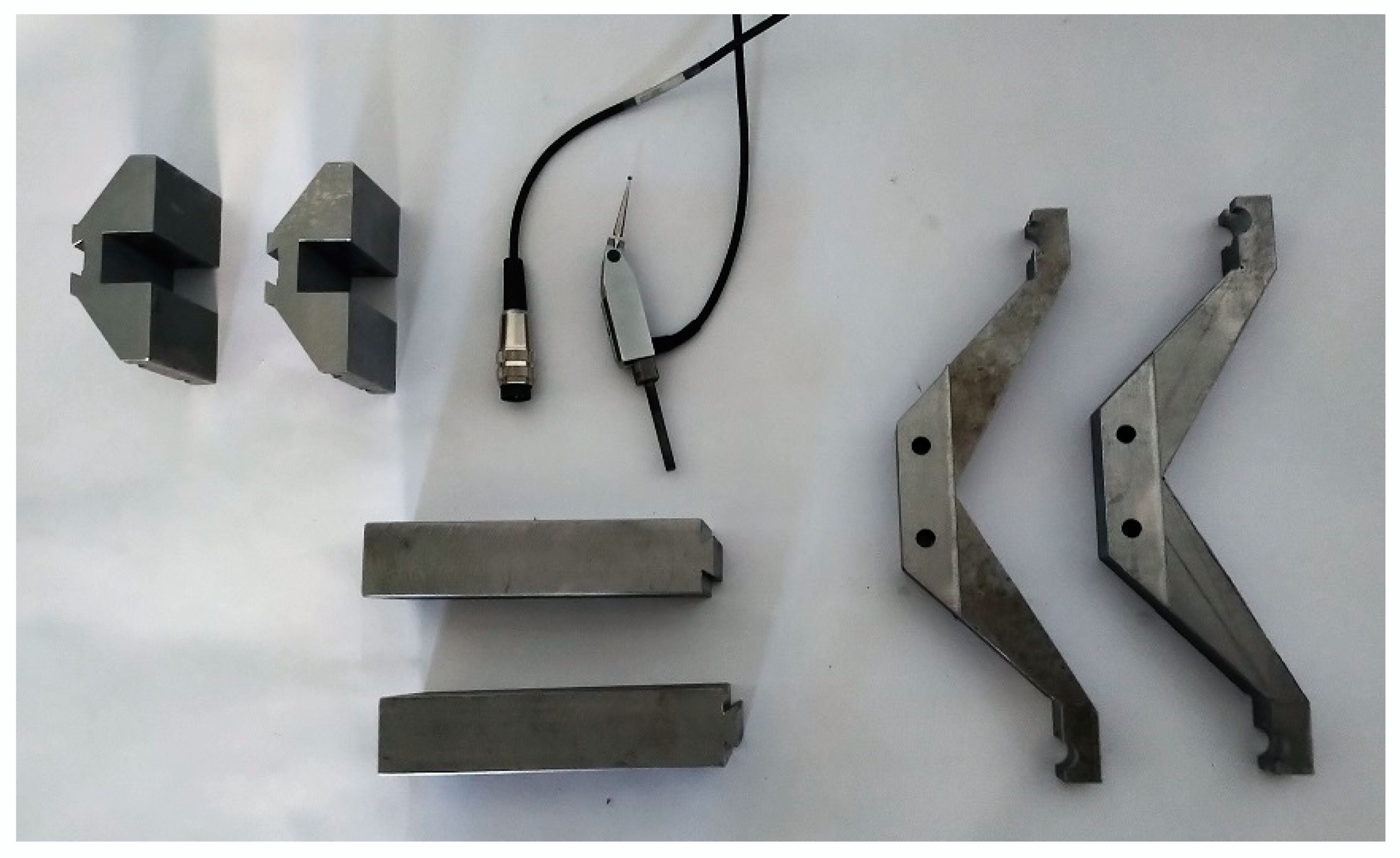
4.2. Example of an Embodiment of a Device to Stabilize Reaction Forces at Supports

After performing calculations to confirm the validity of the proposed solution, counterweights were formed to obtain the ideal slenderness and compactness of the design and manufacture and assembly technology. This solution made it possible to minimize the weight of the entire device. Based on the adopted assumptions, the design documentation was drawn up that contained information on the shape and dimensions of the vee block and guide strip (Figure 15a), weights serving as counterweights (Figure 15b), as well as their material data.
Adding counterweights to a shaft structure ensures constant reaction forces and virtually zero deflection at each supported main journal during shaft rotation. This insight was used as the basis to engineer a device to supplement the shaft with replaceable counterweights.
We propose performing crankshaft measurements with a device that is a special, versatile counterweight that supplements the basic version of the shaft with an additional mass to stabilize the reaction forces on supported main journals. The main element of the device (Figure 16) is the vee block (1), which, using an elastic band 4 (clamp), is fixed (attached) on the crank web (3) opposite the crankpin (11).
The vee block (1) is clamped to the crank web (3) with a band (4), wing nuts (7), and clamping screws (5), which are rigidly coupled to the band (4) on one side, placed in the side grooves of the vee block (1) on the other side, and placed in cylindrical holes of inserts (6) that swivel to mate with the vee block (1).
The strip (2) with a guide groove is attached to the vee block (1) using screws (8) and by the groove holding the replaceable counterweight (10) of two similarly shaped elements located on both sides of the guide strip, clamped around the strip (2) with the screw (9). The weights (counterweight) on both sides of the guide strip (2) are chosen so that the center of gravity of the device with the weights is as recommended in points 2 to 4 of section (c). They are also located in the plane containing the axes of symmetry of the main journal (17) and the crankpin (11), which are part of the crank on which the device is installed. The measuring system supplementing the proposed device is also useful for correctly positioning the entire device on the crank, to ensure that its center of gravity is situated opposite the center of gravity of the crank-forming masses.
The supplementary measurement system consists of a displacement sensor (12) with a pivoting stylus (13) that is positioned and pre-tensioned by moving the probe along the bed (16) (permanently attached to guide 2) with a screw and adjustment knob (15) and a rotatable nut (14) in the groove of guide (2). The device is positioned on the crank by turning the vee block (2) along the circumference of the crank web (3) profile while observing changes in the displacement sensor readings (12), whose probe stylus tip (13) is in contact with the cylindrical surface of the main journal (17). The position is adjusted until finding the maximum return position of the probe stylus (13) of the displacement sensor (12)—as displayed on the digital read-out (not shown in Figure 16—which cooperates with the displacement sensor. Then, the instrument is fixed on the crank with a clamp (4). The prototypes of vee blocks, counterweights and the sensor are shown in Figure 17.
The device and method are versatile because the device can be quickly installed on any crank web shape, allowing it to be used to measure crankshafts of any designs and dimensions. The method to prepare and attach the counterweight makes it possible to replace it quickly and to reposition it along the guide strip so that the counterweight mass and the moment of the mass can be changed. This makes it possible to adjust the position of the center of gravity of the balancing mass per the measurement producers given in points 2–4 of Section 4.2. To increase the versatility of the device, a counterweight can be used in the form of a container filled with a liquid (lead). By changing the liquid inside the container, the mass of the counterweight can be changed, thus changing the operating parameters of the device and its applications. It is also possible to optimize the design of the device by reducing its dimensions while maintaining its functionality.

5. Summary

The advantages of the proposed device are:
  • Increased accuracy of measurements of the geometry of large journals resting on fixed supports;
  • The solution is versatile and can be used for different shafts and support methods;
  • The solution does not require changing the construction and operation of the shaft support system at the measurement bench;
  • There is no need to use flexible supports that exert variable reaction forces depending on the angle of rotation of the supported shaft, which significantly simplifies the measurement system;
  • This solution may complement existing measurement systems by increasing their accuracy at little additional cost.

6. Patents

  • Nozdrzykowski K., Chybowski L., Grządziel Z., Device for increasing accuracy of geometry measurements for large size crankshafts and a method for geometry measurements for large size crankshafts. Polish Patent Office, P.433522.
  • Nozdrzykowski, K. Device for measuring positional deviation of axis of crankshaft pivot set. Polish 527 Patent Office, PL393829-A1; PL218653-B1.

Author Contributions

Conceptualization, L.C., K.N., Z.G., A.J. and W.P.; methodology, L.C., K.N., Z.G., A.J. and W.P.; software, L.C., K.N., Z.G., A.J. and W.P.; validation, L.C., K.N., Z.G., A.J. and W.P.; formal analysis, L.C., K.N., Z.G., A.J. and W.P.; investigation, L.C., K.N., Z.G., A.J. and W.P.; resources, L.C., K.N., Z.G., A.J. and W.P.; data curation, L.C., K.N., Z.G., A.J. and W.P.; writing—original draft preparation, L.C., K.N., Z.G., A.J. and W.P.; writing—review and editing, L.C., K.N., Z.G., A.J. and W.P.; visualization, L.C., K.N., Z.G., A.J. and W.P.; project administration, L.C., K.N., Z.G., A.J. and W.P.; supervision, L.C., K.N., Z.G., A.J. and W.P.; funding acquisition, L.C., K.N., Z.G., A.J. and W.P. All authors have read and agreed to the published version of the manuscript.

Funding

This research and APC was co-funded by the Ministry of Science and Higher Education of Poland from Grant 534 1/S/KPBMiM/20.

Conflicts of Interest

The authors declare no conflict of interest.

References

  1. Fonte, M.; Duarte, P.; Anes, V.; Freitas, M.; Reis, L. On the assessment of fatigue life of marine diesel engine crankshafts. Eng. Fail. Anal. 2015, 56, 51–57. [Google Scholar] [CrossRef]
  2. Sun, J.; Wang, J.; Gui, C. Whole crankshaft beam-element finite-element method for calculating crankshaft deformation and bearing load of an engine. Proc. Inst. Mech. Eng. Part J J. Eng. Tribol. 2010, 224, 299–303. [Google Scholar] [CrossRef]
  3. Zhao, Y.; Cao, S.Q. Modal Analysis of Large Marine Crankshaft. Front. Manuf. Des. Sci. III 2013, 271–272, 1022–1026. [Google Scholar] [CrossRef]
  4. Siemiątkowski, Z.; Rucki, M.; Morozow, D.; Martynowski, R.; Shelkovoy, A.; Gutsalenko, Y. Study of the geometry of grinding machines used for large scale crankshaft machining. Cut. Tools Technol. Syst. 2019, 91, 207–219. [Google Scholar] [CrossRef]
  5. Nozdrzykowski, K.; Chybowski, L. A Force-Sensor-Based Method to Eliminate Deformation of Large Crankshafts during Measurements of Their Geometric Condition. Sensors 2019, 19, 3507. [Google Scholar] [CrossRef] [Green Version]
  6. Niezgodziński, M.; Niezgodziński, T. Wytrzymałość Materiałów [Resistance of Materials]; PWN: Warsaw, Poland, 1979. [Google Scholar]
  7. Łukomski, Z. Technologia Spalinowa Silników Kolejowych i Okrętowych [Exhaust Gas Technology of Railway and Marine Engines]; WKiŁ: Warsaw, Poland, 1972. [Google Scholar]
  8. Dunaj, P.; Dolata, M.; Berczyński, S. Model Order Reduction Adapted to Steel Beams Filled with a Composite Material. In Information Systems Architecture and Technology: Proceedings of 39th International Conference on Information Systems Architecture and Technology–ISAT 2018; Springer: Cham, Switzerland, 2019; pp. 3–13. [Google Scholar]
  9. Kazienko, D.; Chybowski, L. Instantaneous Rotational Speed Algorithm for Locating Malfunctions in Marine Diesel EnginesLocating Malfunctions in Marine Diesel Engines. Energies 2020, 13, 1396. [Google Scholar] [CrossRef] [Green Version]
  10. Kazienko, D. The analysis of class survey methods and their impact on the reliability of marine power plants. Sci. J. Marit. Univ. Szczec. 2019, 55, 34–43. [Google Scholar] [CrossRef]
  11. Bejger, A.; Drzewieniecki, J.B. The Use of Acoustic Emission to Diagnosis of Fuel Injection Pumps of Marine Diesel Engines. Energies 2019, 12, 4661. [Google Scholar] [CrossRef] [Green Version]
  12. Siemiątkowski, Z.; Rucki, M.; Lavrynenko, S. Investigations on the modeled shrink-fitted joints of assembled crankshafts. J. Mach. Constr. Maint. 2018, 1, 33–44. [Google Scholar]
  13. Vijaya Ramnath, B.; Elanchezhian, C.; Jeykrishnan, J.; Ragavendar, R.; Rakesh, P.K.; Dhamodar, J.S.; Danasekar, A. Implementation of Reverse Engineering for Crankshaft Manufacturing Industry. Mater. Today Proc. 2018, 5, 994–999. [Google Scholar] [CrossRef]
  14. Yamagata, H. The crankshaft. In The Science and Technology of Materials in Automotive Engines; Elsevier: Amsterdam, The Netherlands, 2005; pp. 165–206. [Google Scholar]
  15. Dunaj, P.; Marchelek, K.; Chodźko, M. Application of the finite element method in the milling process stability diagnosis. J. Theor. Appl. Mech. 2019, 57, 353–367. [Google Scholar] [CrossRef]
  16. Przetakiewicz, W.; Bryll, K.; Kostecka, E.; Stochła, D.; Staude, M. Application of microscopy in the assesment of porosity in composite casts saturated with silumin. In Materials, Technologies, Constructions. “Special Purpose Materials”; Oficyna Wydawnicza Politechniki Rzeszowskiej: Rzeszów, Poland, 2019; pp. 21–28. [Google Scholar]
  17. Adamczak, S.; Janecki, D.; Stępień, K. Problems of Mathematical Modelling of Rotary Elements. In Proceedings of the International Symposium for Production Research 2018; Springer International Publishing: Cham, Switzerland, 2019; pp. 747–752. [Google Scholar]
  18. Janecki, D.; Stępień, K.; Adamczak, S. Investigating methods of mathematical modelling of measurementand analysis of spherical surfaces. In Proceedings of the X International Symposium on Measurement and Quality Control–ISMQC 2010, Osaka, Japan, 5–9 September 2010; pp. 1–4. [Google Scholar]
  19. PRS. Calculation of Crankshafts for Marine Diesel Engines; Polish Register of Shipping: Gdańsk, Poland, 2012; Volume 8/P. [Google Scholar]
  20. Trebuňa, P.; Mizerák, M.; Trojan, J.; Rosocha, L. 3D scanning as a modern technology for creating 3D models. Acta Tecnol. 2020, 6, 21–24. [Google Scholar] [CrossRef]
  21. Wei, G.; Tan, Q. Measurement of shaft diameters by machine vision. Appl. Opt. 2011, 50, 3246. [Google Scholar] [CrossRef] [PubMed]
  22. Miao, J.; Tan, Q.; Liu, S.; Bao, H.; Li, X. Vision measuring method for the involute profile of a gear shaft. Appl. Opt. 2020, 59, 4183. [Google Scholar] [CrossRef]
  23. Adamczak, S. Odniesieniowe Metody Pomiaru Zarysów Okrągłości Części Maszyn [Reference Methods for Measuring the Roundness Profiles of Machine Parts]; Kielce University of Technology: Kielce, Poland, 1998. [Google Scholar]
  24. Janecki, D.; Zwierzchowski, J.; Cedro, L. A problem of optimal cylindricity profile matching. Bull. Polish Acad. Sci. Tech. Sci. 2015, 63, 771–779. [Google Scholar] [CrossRef]
  25. Taylor Hobson. Talyrond® 2000 A High Precision Large Capacity Roundness System; Taylor Hobson: Berwyn, PA, USA, 2019. [Google Scholar]
  26. Mahr MarForm. Form Measuring Instruments; Mahr MarForm: Providence, RI, USA, 2020. [Google Scholar]
  27. Adamczak, S. Pomiary Geometryczne Powierzchni, Zarysy Kształtu, Falistości i Chropowatości; PWN: Warsaw, Poland, 2008. [Google Scholar]
  28. Carl Zeiss. UPMC CARAT S-ACC. Specifications and Performance Features; Carl Zeiss: Oberkochen, Germany, 2002. [Google Scholar]
  29. Wenzel Bridge Machines. Available online: https://www.wenzel-group.com/en/product/category/bridge-machines/ (accessed on 17 May 2020).
  30. ADCOLE 1200: Cylindrical Crankshaft/Camshaft Gage. Available online: https://www.adcole.com/portfolio/1200-cylindrical-crankshaft-camshaft-gage/ (accessed on 24 June 2020).
  31. Michalski, R.; Wieczorowski, M.; Glazowski, P.; Gapiński, B. Analysis of the Influence of Support During Measurement Using Coordinate Measuring Techniques. Adv. Sci. Technol. Res. J. 2019, 13, 22–29. [Google Scholar] [CrossRef]
  32. Urey, H.; DeWitt IV, F.A.; Luanava, S. Optical scanners for high-resolution RSD systems. In Proceedings of the SPIE-The International Society for Optical Engineering; Rash, C.E., Reese, C.E., Eds.; SPIE: Bellingham, WA, USA, 2002; Volume 4711, pp. 214–223. [Google Scholar]
  33. Bernal, C.; de Agustina, B.; Marín, M.M.; Camacho, A.M. Performance Evaluation of Optical Scanner Based on blue LED Structured Light. Procedia Eng. 2013, 63, 591–598. [Google Scholar] [CrossRef] [Green Version]
  34. Kuş, A. Implementation of 3D Optical Scanning Technology for Automotive Applications. Sensors 2009, 9, 1967–1979. [Google Scholar] [CrossRef]
  35. GOM ATOS Triple Scan-Industrial Optical 3D Digitizer. Available online: https://www.gom.com/metrology-systems/atos/atos-triple-scan.html (accessed on 17 May 2020).
  36. Moghtaderi, M. Diesel Engine Crankshaft Deflection Measurement. Available online: https://www.linkedin.com/pulse/diesel-engine-crankshaft-deflection-measurement-mahmoud-moghtaderi/ (accessed on 28 August 2019).
  37. MAN B&W Diesel A/S. MAN B&W 50-90 MC/MCE Instruction Manual; Works Written by an Organization or a Committee: Copenhagen, Denmark, 2013. [Google Scholar]
  38. Nozdrzykowski, K.; Chybowski, L.; Dorobczyński, L. Model-Based Estimation of the Reaction Forces in an Elastic System Supporting Large-Size Crankshafts During Measurements of their Geometric Quantities. Measurement 2020, 155, 107543. [Google Scholar] [CrossRef]
  39. Chybowski, L.; Nozdrzykowski, K.; Grządziel, Z.; Dorobczyński, L. Evaluation of Model-based Control of Reaction Forces at the Supports of Large-size Crankshafts. Sensors 2020, 20, 2654. [Google Scholar] [CrossRef]
  40. Leontopoulos, C.; Davies, P.; Park, K.R. Shaft alignment analysis: Solving the reverse problem. Proc. Inst. Mar. Eng. Sci. Technol. Part B J. Mar. Des. Oper. 2005, 8B, 3–12. [Google Scholar]
  41. Tiwari, R.; Lees, A.W.; Friswell, M.I. Identification of dynamic bearing parameters: A review. Shock Vib. Dig. 2004, 36, 99–124. [Google Scholar] [CrossRef]
  42. Lees, A.W. Vibration Problems in Machines Diagnosis and Resolution; CRC Press: Boca Raton, FL, USA, 2016. [Google Scholar]
  43. Friswell, M.I.; Mottershead, J.E. Finite Element Model Updating in Structural Dynamics; Springer: Berlin/Heidelberg, Germany, 1996. [Google Scholar]
  44. Hirdaris, S.E.; Lees, A.W. A conforming unified finite element formulation for the vibration of thick beams and frames. Int. J. Numer. Methods Eng. 2005, 62, 579–599. [Google Scholar] [CrossRef]
  45. Yu, B.Y.; Feng, Q.K.; Yu, X.L. Modal and vibration analysis of reciprocating compressor crankshaft system. In 7th International Conference on Compressors and their Systems 2011; Elsevier: Amsterdam, The Netherlands, 2011; pp. 295–303. [Google Scholar]
  46. Bejger, A.; Chybowski, L.; Gawdzińska, K. Utilising elastic waves of acoustic emission to assess the condition of spray nozzles in a marine diesel engine. J. Mar. Eng. Technol. 2018. [Google Scholar] [CrossRef] [Green Version]
  47. Mourelatos, Z.P. A crankshaft system model for structural dynamic analysis of internal combustion engines. Comput. Struct. 2001, 79, 2009–2027. [Google Scholar] [CrossRef]
  48. Tsitsilonis, K.; Mavrelos, C.; Stefanidis, F.; Gad, A.; Timmerman, M. Concept Design Considerations for the Next Generation of Mega-Ships. In Proceedings of the 13th International Marine Design Conference (IMDC 2018); Taylor & Francis: Boca Raton, FL, Poland, 2018; pp. 579–588. [Google Scholar]
  49. Tsitsilonis, K.-M.; Theotokatos, G.; Xiros, N.; Habens, M. Systematic Investigation of a Large Two-Stroke Engine Crankshaft Dynamics Model. Energies 2020, 13, 2486. [Google Scholar] [CrossRef]
  50. Arnulfi, G.L.; Blanchini, F.; Giannattasio, P.; Micheli, D.; Pinamonti, P. Extensive study on the control of centrifugal compressor surge. Proc. Inst. Mech. Eng. Part A J. Power Energy 2006, 220, 289–304. [Google Scholar] [CrossRef]
  51. Nozdrzykowski, K.; Grządziel, Z.; Harušinec, J. Determining and Analysing Support Conditions at Variable Construction of Crankshafts. New Trends Prod. Eng. 2018, 1, 553–560. [Google Scholar] [CrossRef] [Green Version]
Figure 1. Device with centers for measuring crankshaft roundness profiles: 1—tested element, 2—center, 3—sensor, 4—tripod, 5—indicator device, 6—computer, 7—recorder.
Applsci 10 04722 g001
Figure 2. Non-reference measurement methods: (a) system with a rotary table; (b) system with rotating spindle.
Applsci 10 04722 g002
Figure 3. Talyrond 2000, an instrument with a rotary table for performing non-reference measurements of crankshaft geometry (courtesy of Taylor Hobson).
Applsci 10 04722 g003
Figure 4. Examples of machines used for coordinate measurements of the geometry of large machinery components, including crankshafts: (a) Carl Zeiss CARAT UPMC 850 (courtesy of Zeiss); (b) Wenzel LH 1512 (courtesy of Wenzel); (c) ADCOLE 1200 (courtesy of ADCOLE).
Applsci 10 04722 g004
Figure 5. Measuring station for crankshafts for medium-speed engines.
Applsci 10 04722 g005
Figure 6. Crank web deformation measurements: (a) view of the instrument; (b) interpretation of measurement results.
Applsci 10 04722 g006
Figure 7. SAJD measurement system: (a) layout of the system; (b) example of application (courtesy of S. Adamczak and T. Dobrowolski).
Applsci 10 04722 g007
Figure 8. The design of the “ideal” shaft that ensured zero deflection at journals as the shaft rotates.
Applsci 10 04722 g008
Figure 9. Analyzed counterweight design variants: (a) square/rectangle counterweight; (b) half-circle counterweight; (c) “hammer”-shaped counterweight.
Applsci 10 04722 g009
Figure 10. View of the crankshaft of the Buckau Wolf R8 DV 136 medium-speed main propulsion engine [39].
Applsci 10 04722 g010
Figure 11. The modified design of the shaft equipped with counterweights, ensuring negligible changes in the reaction forces of supports, regardless of the shaft rotation angle.
Applsci 10 04722 g011
Figure 12. Activity diagram for the process of measuring crankshaft geometry using temporary counterweights.
Applsci 10 04722 g012
Figure 13. Distribution of the reaction forces ensuring zero deflection at the main journals for the crankshaft of a medium-speed engine of the main propulsion of a ship in (a) polar and (b) Cartesian coordinates [51].
Applsci 10 04722 g013
Figure 14. The distribution of reaction forces for near-zero deflections at main journals for the modified crankshaft design in (a) polar and (b) Cartesian coordinates.
Applsci 10 04722 g014
Figure 15. Structural elements of the device fixing the center of gravity in the shaft axis of a single crank: (a) vee blocks and guide strips; (b) counterweights.
Applsci 10 04722 g015
Figure 16. The device used to stabilize reaction forces, installed on the shaft’s crank.
Applsci 10 04722 g016
Figure 17. View of key components of the device used to stabilize reaction forces.
Applsci 10 04722 g017
Table 1. Crankshaft measurement methods and techniques categorized by their overall dimensions and measurement conditions.
MethodMeasurement TechniqueFixingAdditional SupportPlane of the Shaft AxisMeasurement System ParametersSupport ConditionsEngine Type
Non-reference– in a device with centerscentersnonehorizontalnoneuncontrolledhigh speed
– in a devicewith a rotary table– centers
– chuck
– directly on a table
verticalhigh speed,
medium speed
with a rotary spindle
– using a measurement system with controlled reaction forces at the supportby external faces, in centersMulti-point, on supports/vee blockshorizontalα, γ, φ, l1, Lmonitoredmedium speed
low speed
Reference- using vee blocksin 2 vee blocksnonehorizontalnoneuncontrolled
indirect control by measuring the deformation of crank webs (springing measurement)
high speed,
medium speed
in 4 vee blocksselectivelymedium speed
in n vee blocksmulti-pointlow speed
– with a measurement system with controlled reaction forces at the supportby outermost external main journals in vee blocksMulti-point, on flexible supportshorizontalα, γ, φ, l1, Lmonitoredmedium speed
low speed
Others- coordinate measuring technique
- using measurement arms
in 2 vee blocksnonehorizontalnoneuncontrolledhigh speed
in 4 vee blocksselectivelymedium speed
in n vee blocksmulti-pointlow speed
– scanning,
– photometry
in n vee blocksmulti-pointlow speed
Table 2. Example of the calculation of the reaction forces ensuring zero deflection at the main journals for the crankshaft in a medium-speed Buckau Wolf R8 DV 136 engine of the main propulsion of a ship [39].
Angular Position (°CA)Main Journal Number (-)
12345678910
Reaction Forces in Main Journals (N)
0731.62988.50871.121166.33847.891093.01852.041142.22988.15603.47
15727.481005.43823.761237.24796.421123.70799.741212.93944.12613.51
30737.46989.14822.941253.23795.301108.89797.221231.62933.95614.59
45758.88943.98868.881210.01844.821052.54845.151193.29960.37606.42
60786.00882.05949.281119.16931.72969.75930.691108.201016.30591.19
75811.57819.941042.601005.031032.70882.711030.91999.161086.75572.98
90828.72774.301123.82898.191120.71814.741118.97895.381152.84556.67
105832.87757.351171.18827.291172.17784.051171.26824.671196.87546.62
120822.89773.651172.00811.301173.29798.871173.78805.981207.04545.54
135801.47818.821126.05854.531123.77855.221125.85844.311180.62553.71
150774.33880.761045.65945.371036.88938.001040.31929.401124.69568.94
165748.76942.87952.341059.50935.901025.04940.091038.441054.24587.16
180731.62988.50871.121166.33847.891093.01852.041142.22988.15603.47
195727.481005.43823.761237.24796.421123.70799.741212.93944.12613.51
210737.46989.14822.941253.23795.301108.89797.221231.62933.95614.59
225758.88943.98868.881210.01844.821052.54845.151193.29960.37606.42
240786.00882.05949.281119.16931.72969.75930.691108.201016.30591.19
255811.57819.941042.601005.031032.70882.711030.91999.161086.75572.98
270828.72774.301123.82898.191120.71814.741118.97895.381152.84556.67
285832.87757.351171.19827.291172.17784.051171.26824.671196.87546.62
300822.89773.651172.00811.301173.29798.871173.78805.981207.04545.54
315801.47818.821126.05854.531123.77855.221125.85844.311180.62553.71
330774.33880.761045.65945.371036.88938.001040.31929.401124.69568.94
345748.76942.86952.341059.50935.901025.04940.091038.441054.24587.16
360731.62988.50871.121166.33847.891093.01852.041142.22988.15603.47
Table 3. Calculation of the reaction forces ensuring virtually zero deflection at main journals, performed for the modified crankshaft design.
Angular Position (°CA)Main Journal Number (-)
12345678910
Reaction Forces in Main Journals (N)
0724.001241.001645.001595.001601.001607.001603.001589.001680.00913.00
15725.601241.001644.001595.001601.001607.001603.001590.001680.00912.40
30726.101242.001642.001596.001601.001607.001602.001591.001676.00913.70
45725.401246.001639.001597.001602.001606.001602.001594.001671.00916.60
60723.801250.001635.001598.001602.001606.001603.001596.001665.00920.30
75721.601253.001632.001599.001602.001605.001603.001598.001661.00923.90
90719.501256.001630.001600.001602.001605.001604.001599.001658.00926.30
105717.901256.001630.001600.001602.001605.001605.001598.001658.00926.90
120717.401255.001633.001599.001602.001605.001605.001597.001662.00925.60
135718.101251.001636.001598.001601.001605.001605.001594.001667.00922.70
150719.701247.001640.001597.001601.001606.001605.001592.001673.00919.00
165721.901244.001643.001596.001601.001606.001604.001590.001678.00915.40
180724.001241.001645.001595.001601.001607.001603.001589.001680.00913.00
195725.601241.001644.001595.001601.001607.001603.001590.001680.00912.40
210726.101242.001642.001596.001601.001607.001602.001591.001676.00913.70
225725.401246.001639.001597.001602.001606.001602.001594.001671.00916.60
240723.801250.001635.001598.001602.001606.001603.001596.001665.00920.30
255721.601253.001632.001599.001602.001605.001603.001598.001661.00923.90
270719.501256.001630.001600.001602.001605.001604.001599.001658.00926.30
285717.901256.001630.001600.001602.001605.001605.001598.001658.00926.90
300717.401255.001633.001599.001602.001605.001605.001597.001662.00925.60
315718.101251.001636.001598.001601.001605.001605.001594.001667.00922.70
330719.701247.001640.001597.001601.001606.001605.001592.001673.00919.00
345721.901244.001643.001596.001601.001606.001604.001590.001678.00915.40
360724.001241.001645.001595.001601.001607.001603.001589.001680.00913.00

