1. Introduction
In the evolution of modern transportation systems, maglev trains have emerged as a crucial development direction for future rail transit, attributed to their non-mechanical contact between vehicle and track, no wheel–rail adhesion, high operating speed, excellent stability, superior ride comfort, strong gradient climbing capacity, and environmental friendliness. Rapid advancements in maglev transportation have been witnessed in recent years.
For high-speed EMS-type maglev trains, an active guidance system is indispensable to meet the stringent requirements for curve negotiation at elevated speeds. Operating independently from the levitation system, this subsystem provides lateral guidance forces to continuously correct deviations from the track centerline, ensuring the train travels along the track centerline. While guidance technologies for medium- and low-speed applications are relatively mature, high-speed and ultra-high-speed operating conditions still face problems, including lateral sway and operational instability. Consequently, in-depth research into guidance system control holds substantial theoretical and practical significance.
Current research on high-speed maglev guidance primarily focuses on control methodologies and system dynamics. Among them, the research on guidance dynamics has been relatively mature, and a relatively complete model can be established to describe the actual work of the guidance system. For instance, a comprehensive guidance dynamics model for EMS maglev trains was developed by Zhao et al. [
1]. Li et al. [
2] used multi-rigid-body dynamics modeling to explain the causes of friction between the guide electromagnet and the track by combining experiments. From a control perspective, current research primarily focuses on improving controller performance: Hao et al. [
3,
4,
5] proposed adaptive control, robust control, and track irregularity compensation control strategies respectively; Wu et al. [
6,
7] realized the optimal design of the guidance control system by constructing a single vehicle guidance dynamics model and combining simulation analysis. Zhai et al. [
8] established the mathematical model of the active guidance control system of high-speed maglev trains around the model uncertainty problem of the active guidance control system of high-speed maglev trains, and designed the robust controller by using H∞ control theory, which improved the safety and reliability of the system. The 2-DOF control method of active suspension and guidance [
9] is adopted, which improves the lateral dynamic response performance of the vehicle. Zuo et al. [
10] focused on the fault-tolerant control technology of the guidance system, which enhanced the reliability of the guidance control under complex working conditions. Wang et al. [
11] provided a multi-technical path for the optimization and upgrading of the guidance system of high-speed maglev trains by using linear quadratic optimal control and particle swarm optimization. Li et al. [
12] adopted the method of Active Disturbance Rejection Control combined with genetic algorithm optimization, which effectively improved the guidance control performance. For the quasi-high-speed maglev train, Min Kim et al. [
13] realized the active control of lateral displacement through linearization modeling and PDA controller design. Chang-Hyun Kim et al. [
14] incorporated the yaw motion of the bogie into the control law and used a linear observer to achieve state feedback and improve lateral stability.
Although existing research has made strides in parameter optimization and operational adaptability, high-speed conditions exacerbate the challenges posed by the system’s inherent strong nonlinearities, parameter variations, and complex external disturbances. These factors lead to significant guidance gap fluctuations, elevating safety risks, degrading ride quality and comfort, and potentially shortening equipment service life. Therefore, further investigation into control strategies with enhanced adaptive capability and multi-objective optimization remains necessary to mitigate these issues. Addressing the common challenges of strong nonlinearity, time-varying parameters, and complex disturbances in maglev systems, targeted explorations have been conducted in levitation system research. Chen et al. [
15] constructed a vehicle–track–bridge coupled dynamics model. Through modal analysis of multi-span guideways and co-simulation, they revealed the performance degradation limitations of PID control under high-speed conditions, confirming that traditional linear control struggles to adapt to dynamic disturbance scenarios. Furthermore, Chen et al. [
16] proposed an adaptive inverse control algorithm based on an RBF neural network state observer. By enabling real-time estimation of system states and parameter matrices, combined with output constraint design, this approach significantly enhanced the disturbance rejection capability and response speed under time-varying mass disturbances, providing an effective pathway for intelligent control of maglev systems.
Aiming at the problems of strong nonlinearities, time-varying parameters and complex disturbances in the maglev guidance system, this paper designs an intelligent control algorithm, DDPG-STSMC, which combines Super-Twisting Sliding Mode Control (STSMC) and the Deep Deterministic Policy Gradient (DDPG) algorithm to control the maglev train guidance unit. With the help of the model-free adaptive learning ability of reinforcement learning, the self-tuning of the parameters of the super-twisting sliding mode controller is realized, and the dynamic stability, control accuracy and working condition adaptation ability of the maglev train guidance system are further improved. Compared with the existing methods, such as traditional PID, the proposed method has stronger robustness and better real-time control performance when dealing with nonlinearity and uncertainty. This study builds a simulation environment based on actual engineering scenarios and demonstrates the engineering application potential of the proposed control method by constructing a high-fidelity virtual verification system, so as to reduce the cost of trial and error for subsequent hardware experiments.
The rest of this paper is organized as follows: In
Section 1, the dynamic model of the maglev system is established. In
Section 2, the super-twisting sliding mode controller is proposed, and its stability is proved theoretically. In
Section 3, the DDPG-STSMC controller is proposed, which sets the agent based on the system performance requirements and trains the agent.
Section 4 verifies the superior performance of the proposed control method through simulation results.
Section 5 provides a discussion of the results and their implications.
Section 6 gives the conclusion of this paper.
2. High-Speed Maglev Guidance System Modeling
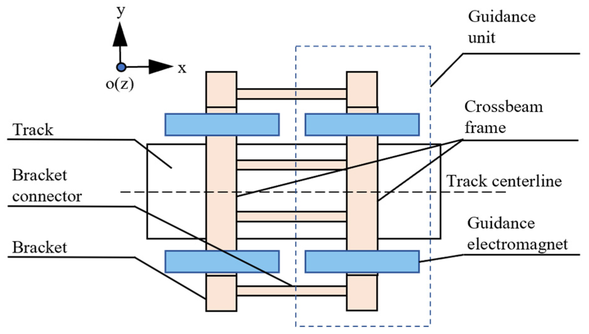
In order to increase the redundancy of the system, the guiding electromagnet is connected by an overlapping structure to form a guiding overlapping system. The overlapping system is composed of two guiding units. The schematic diagram of the overlapping system is shown in
Figure 1. As the two units are controlled independently, the controller design focuses on a single-ended guidance system.
The two magnetic pole groups of the single-ended steering system are equivalent to small electromagnets with a specific pole area . The electromagnets on both sides are coupled through the bogie structure. Given the high transverse stiffness and minimal deformation of the connection between the electromagnet and the bogie, the guidance controller design assumes a rigid connection, thereby reducing the model order by simplifying the system into a single rigid body with equivalent mass .
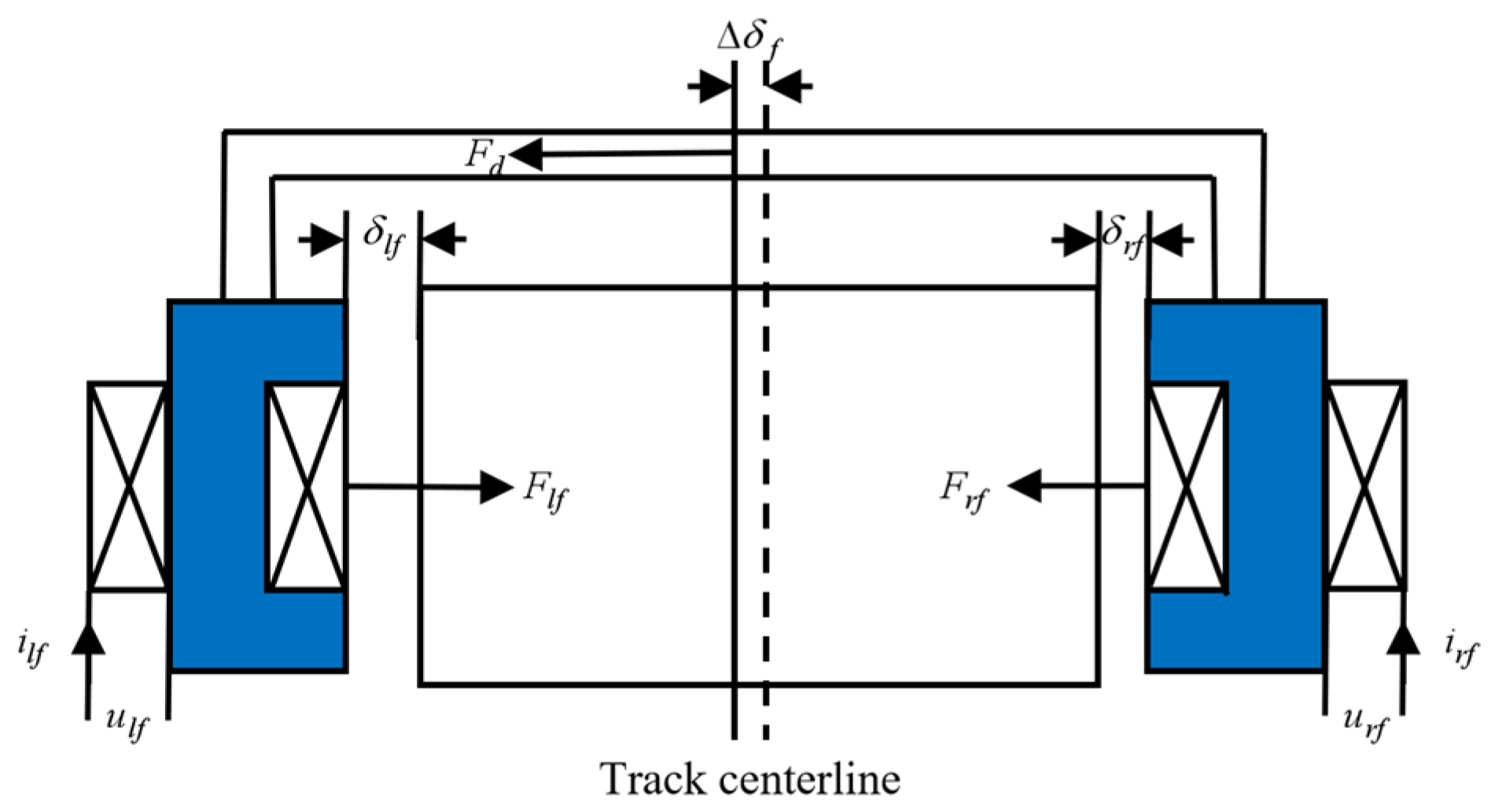
The system model of single-ended guidance is shown in
Figure 2. The electromagnetic forces of the guidance electromagnets on the left and right sides of the track are denoted as
and
, respectively, the coil currents are
and
, the coil voltages are
and
, and the external force acting on the system is
. When the system is in a stable state, the guidance system is exactly at the center of the track. At this time, the gap between the left and right sides is equal to
, and the current of the electromagnet coil is equal to
.
Based on this model, the mathematical model can be obtained by combining the electromagnetic force equation and the dynamic equation. The guidance system is a nonlinear system. By performing the first-order Taylor expansion of the above formula at the static working point
, the state space expression of the system is derived as follows:
where
,
,
,
,
,
is the air gap coefficient;
is the current coefficient;
is the inductance of the coil at the static working point;
is the change value of the guiding gap,
is the change of the current;
is the increased voltage at both ends of the electromagnet.
3. Super-Twisting Sliding Mode Control (STSMC) Design
The considerable time delay between the input voltage and output current of the guidance electromagnet results in a lag of the coil current relative to the control voltage, degrading system performance. Therefore, a cascaded control structure is adopted, separating inner current loop and outer position loop.
The working model of the coil is that the transfer function of voltage to current is as follows:
Here, is the static inductance, and the above model is an inertial element with a time constant of . The adjustment time of the current signal can be calculated as , which indicates that there is a certain delay between the coil current and the voltage. To ensure the coil current can rapidly track the variation in the control signal , correction via a current loop is considered.
The closed-loop transfer function of the corrected model is:
When
= 19.2,
= 0.15 are selected; the time parameter of the model is
. At this point, the adjustment time is shortened to 10 ms (which is basically negligible). In the low-frequency segment, the corrected current loop is approximately a proportional link with a coefficient of 1. It is known that the corrected current loop is equivalent to a proportional link with a coefficient of 1, so
holds. The linearized model of the system is reduced from the original third order to the second order. At this point, let
,
, then the state equation of the reduced-order system is obtained as:
where
,
and
.
In the reduced-order system model, define: , , and .
Super-Twisting Sliding Mode Control (STSMC) is applied to the reduced-order model, and the controller is designed as follows:
Define the sliding surface:
where
is the sliding surface coefficient.
Take the derivative of the sliding surface
; combined with the state equation, we can get:
From the state equation in (4), we have
. Substituting these into the above equation gives:
The control law is defined by the following two equations:
where
and
are control gains, and
is an auxiliary control variable.
Substitute the relevant expression into Equation (8), and arrange to obtain the control law
:
Stability Analysis
Based on Lyapunov stability analysis: To ensure the system is stable on the sliding surface, it is necessary to verify that “the system satisfies within a finite time”.
Select the Lyapunov function as:
Take the derivative of
:
Substitute
and
, and simplify further to obtain:
Since
, according to Barbalat’s lemma [
17], the sliding surface s will converge to 0 within a finite time. When
, the sliding surface satisfies
, whose solution is
, and
. Thus, the system states
.
4. Deep Deterministic Policy Gradient (DDPG) Algorithm
The performance of Super-Twisting Sliding Mode Control (STSMC) critically depends on three parameters: the nonlinear proportional gain , the integral gain and the sliding mode surface coefficient . Traditional offline parameter calibration methods (e.g., empirical trial-and-error, analytical design) are difficult to adapt to dynamic operating conditions. Reinforcement learning can adjust the super-twisting parameters online through real-time interaction with the environment, so that the controller can always maintain the optimal performance under different working conditions, with strong adaptability. At the same time, reinforcement learning can automatically learn the optimal matching relationship between parameters through multi-dimensional action space exploration, breaking through the limitations of human experience. The magnetic levitation guidance system adopts a differential control scheme. The magnitude of the gap change on both sides is equal and the direction is opposite. Therefore, the state space of the agent is set to the gap difference in the one-sided electromagnet guidance, the speed of the electromagnet module, the sliding mode surface and the slip rate . The output action of the agent is the sliding mode surface coefficient , nonlinear proportional gain , and integral gain .
The DDPG algorithm [
18,
19,
20,
21,
22,
23] is a reinforcement learning algorithm for a continuous action space. It is based on the Actor–Critic framework. In order to improve the stability and efficiency of training, DDPG introduces experience replay and TargetNetworks and enhances the exploration ability by adding noise to the action. In addition, DDPG avoids the sharp fluctuation of the target value by softly updating the target network parameters, which further improves the convergence performance of the algorithm.
Design of Super-Twisting Sliding Mode Controller for Guidance System Based on DDPG Algorithm
The framework of the high-speed maglev guidance system controller based on the DDPG algorithm adopts the Actor–Critic framework. The Actor network is a policy network, responsible for outputting the control command
, where
denotes the network parameters. The Critic network is an evaluation network, used to represent the action-value function
(with
as the network parameters). The optimization objective of the evaluation network is to minimize the cost function:
where
;
represents the current state space of the system,
is the current action,
is the reward of the current action,
is the discount factor,
is the next state, and
is the next action.
The data of reinforcement learning is collected in sequence, and there is a strong correlation between the data. Therefore, it is necessary to set an experience replay buffer (Replay Buffer) and an independent target network to break the correlation between the data. In the learning process, the Replay Buffer stores the data tuple obtained by the interaction between the algorithm and the environment. When the Actor–Critic network parameters need to be updated, uniform random sampling is used to extract data from it for training and updating the neural network.
In DDPG, the Actor network and the Critic network have the corresponding target network, Target-Actor network and Target-Critic network, respectively. The network parameters are
and
. The parameters of the target network are updated by:
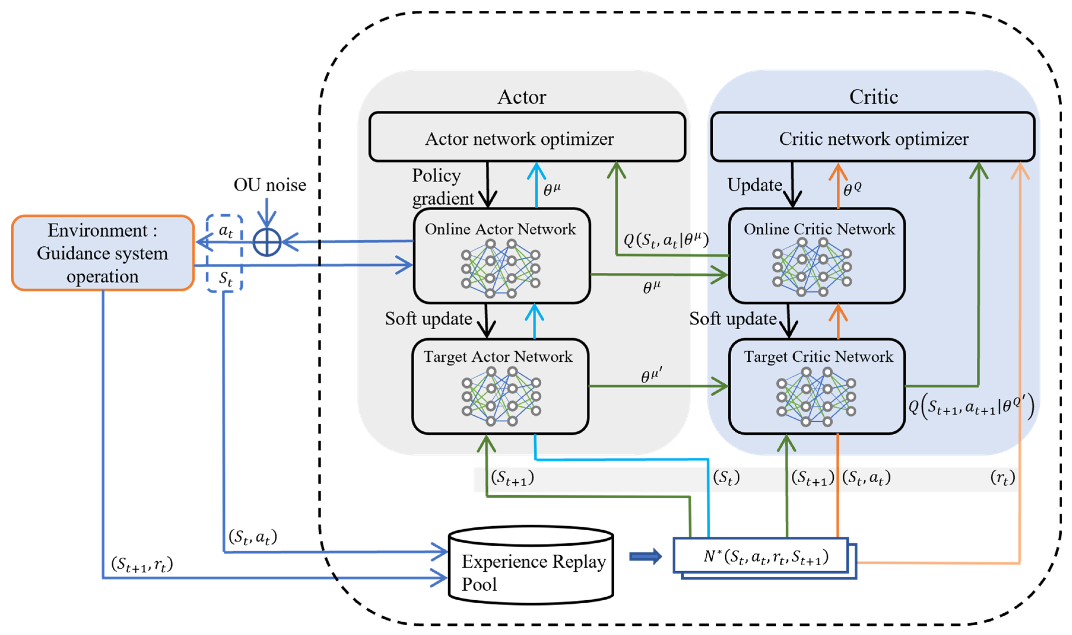
The structure of the Super-Twisting Sliding Mode Control method of the guidance system based on the DDPG algorithm is shown in
Figure 3. Both the Actor and Critic networks consist of two hidden layers, configured with 256 and 128 neurons, respectively, utilizing ReLU activation functions. The learning rates are specified as 10
−4 for the Actor and 10
−3 for the Critic. Specifically, the Actor network accepts the current state of the guidance system as input and generates the STSMC control parameters via linear mapping. The Critic network evaluates the state-action pair by taking the current state and the Actor’s output as inputs to produce the action-value. Meanwhile, the target networks are employed to process the state and action transitions for the subsequent time step.
Since DDPG is a deterministic strategy, it is not as exploratory as the traditional random strategy, so it is necessary to set up an additional exploration strategy. The exploration strategy used in this paper is to add noise to the control parameters of the output of the Actor network:
This study adopts a composite control architecture that embeds a reinforcement learning algorithm within a second-order sliding mode framework supported by rigorous Lyapunov stability proofs. The fundamental stability of the closed-loop system is inherently guaranteed by the STSMC structure. Within the constraints of this stable control framework, the agent performs continuous optimization of key gain parameters. This approach enhances the generalized safety of the method at the structural level; it not only ensures the boundedness of the closed-loop system states but also achieves optimal parameter tuning through agent training. During the training process, the agent explores various situations as much as possible for its own learning. In the actual operation process, if the guidance gap error is too large, it may lead to mechanical structure collision or actuator overload and weaken the running stability. Therefore, the error of the guidance gap should not be too large as the stopping condition of the agent training. Combined with the actual requirements of the running stability, the guidance gap error exceeding 3 mm is set as the termination condition for each agent training episode.
To meet the core requirements of reinforcement learning optimization (high-precision error convergence, sliding mode stability, and chattering suppression), we adopt a hybrid reward function combining positive rewards and negative penalties, based on the reward design framework used in maglev levitation control, which not only clarifies the priority of the core control target, but also adapts the optimization characteristics of different indicators through the type of differential function. The specific design is as follows:
The error threshold reward term is introduced, and its physical meaning is to constrain the guide gap deviation and its differential in a small range, and directly guarantee the steady-state accuracy and dynamic stability of the gap:
Here, is the penalty coefficient for the gap deviation, and is the penalty coefficient for the derivative of the gap deviation.
At the same time, in order to avoid the agent giving up exploration due to no reward when the error is large, it is necessary to introduce an exponential decay reward to promote the system to converge quickly from the large error region to the target:
Here, is the exponential decay reward coefficient for the gap deviation, and is the exponential decay reward coefficient for the derivative of the gap deviation.
A sliding surface constraint term is introduced, whose physical meaning is to guide the super-twisting sliding surface to rapidly converge and ensure the core performance of sliding mode control. The sliding surface convergence reward coefficient is
:
A chattering penalty term is introduced to penalize the agent when chattering occurs in sliding mode control:
Here, is the chattering penalty coefficient for the derivative of the sliding surface.
The final reward function is the sum of the above functions.
The selection of weight coefficients within the reward function significantly influences the convergence process of reinforcement learning. In this study, the reward function is constructed based on two primary principles. First, error normalization is employed to ensure that all reward components remain within the same order of magnitude, thereby enhancing the numerical robustness of the function. Second, a hierarchical weight configuration is implemented according to the priority of control objectives. By designing this magnitude-based hierarchy aligned with task priorities, the policy optimization remains consistent with engineering control goals, structurally eliminating weight conflicts and improving parameter fault tolerance. This ensures that the algorithm maintains strong robustness against infinitesimal perturbations within the parameter space. Furthermore, the parameter tuning process demonstrates that varying reward coefficients within a reasonable range results in negligible fluctuations in both convergence trends and final performance metrics. This indicates that the proposed hybrid reward function possesses a structural buffering capacity against parameter sensitivity. Finally, the parameter values obtained through debugging are: , , , , and .
The pseudo code of the algorithm is given in Algorithm 1.
| Algorithm 1 Pseudo Code of the DDPG Algorithm |
1: Initialize the parameters and of the critic network and the actor network (Critic network input: guidance system state ; Actor network output: parameters , , of the super-twisting sliding mode controller)
2: Initialize the corresponding target network parameters, i.e., ,
3: Initialize the experience replay buffer to store the experience data of the guidance system
4: for episode = 1 to M, do
5: Select action , where is the exploration noise
6: The environment executes , and returns the reward and the next state
7: Store the sample into the experience replay buffer
8: Update the environment state as
9: Policy update:
10: Sample a random minibatch of from
11: Compute
12: Update the critic parameters
13: Update the actor parameters
14: Soft update the target networks:
15: end for |
5. Simulation Verification and Analysis
5.1. Agent Training Results
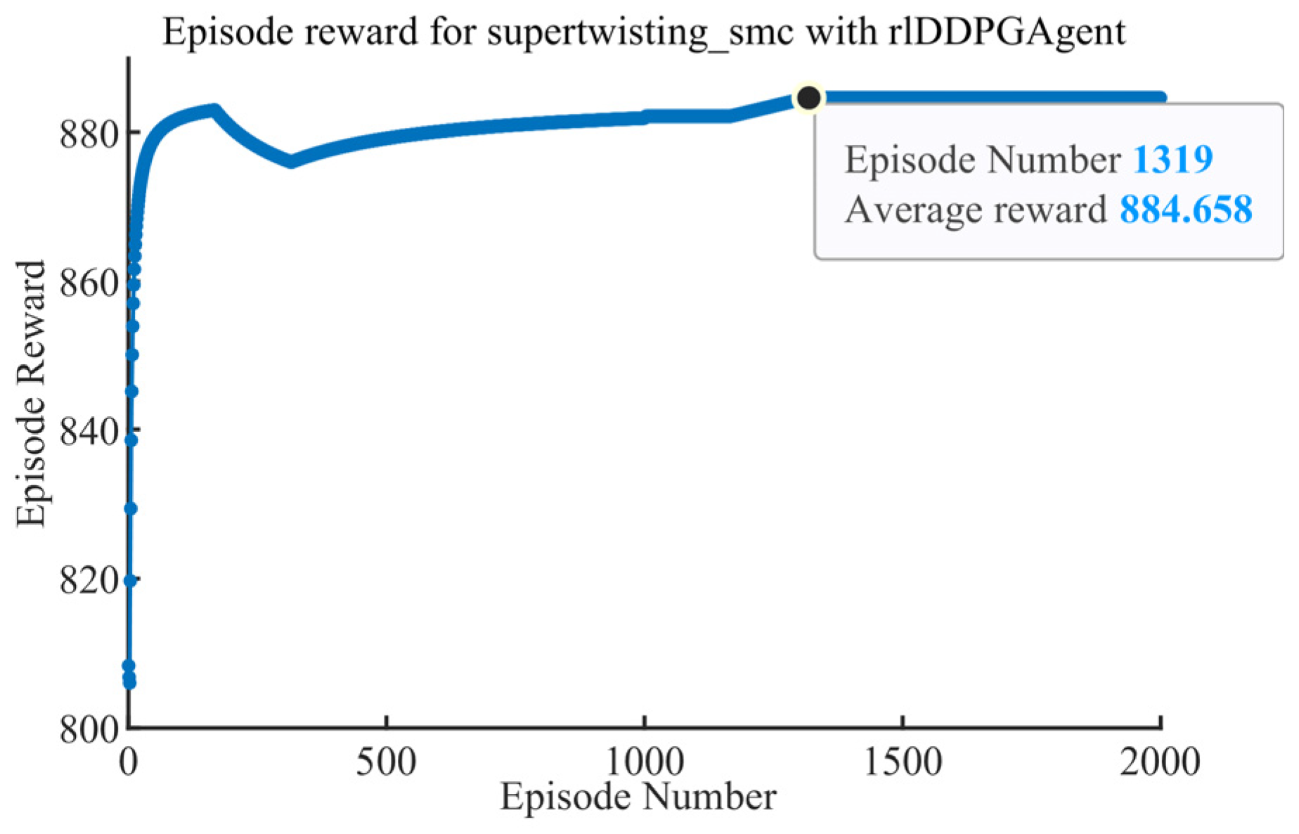
The agent was trained for 2000 episodes with a sampling and control time of 0.01 s. System parameters are listed in
Table 1. The training curve of the reinforcement learning agent is depicted in
Figure 4. As illustrated in
Figure 4, the episodic reward rises sharply during the initial stage of training, indicating that the agent rapidly explores the state space of the guidance system. Subsequently, minor fluctuations (decreases and recoveries) are observed, which correspond to the agent’s fine-grained exploration of the policy space. Thereafter, the reward curve stabilizes and exhibits a gradual upward trend. The reward value approaches its maximum at approximately episode 1319 and remains steady thereafter. This convergence of the reward curve signifies that the agent has successfully learned the optimal policy, marking the completion of the training process.
5.2. Simulation Results and Analysis
As the most widely adopted industrial control standard within the field of maglev transportation engineering, the Proportional–Integral–Derivative (PID) controller serves as a highly significant benchmark for evaluation. To verify the control performance of the trained controller, this method is compared with traditional PID control in different environments. The PID controller is designed based on closed-loop pole placement [
24], and the dynamic performance indices of the closed-loop system are assumed to be:
Combined with practical engineering experience, the parameters of the PID used are . Furthermore, the PID parameters are maintained constant throughout the multi-condition simulation comparisons. This configuration ensures consistency across the diverse evaluative scenarios, thereby rendering the performance comparisons between different control strategies both comparable and objective.
5.2.1. Simulation of Periodic Interference
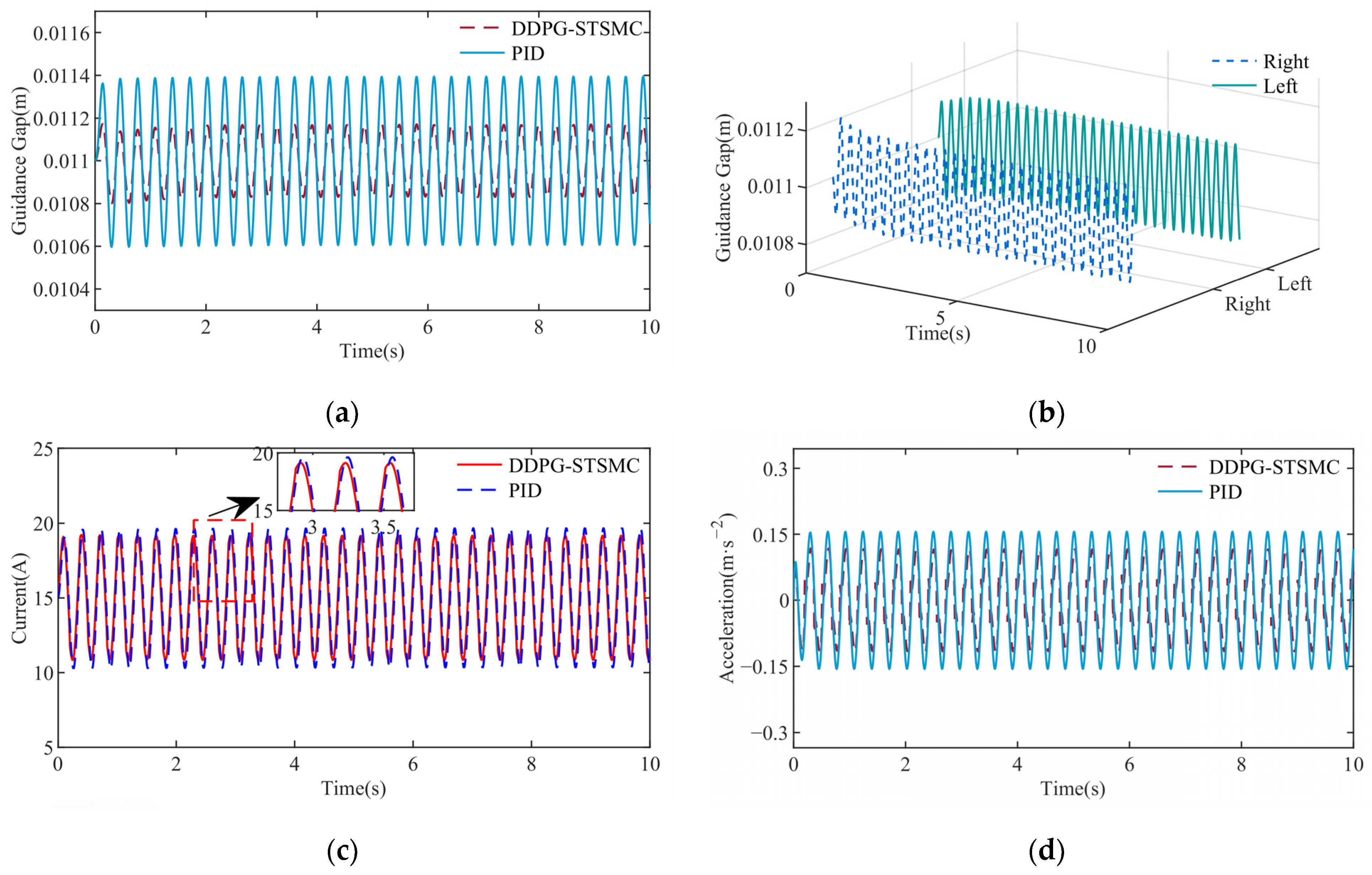
To simulate the periodic interference during the operation of the maglev train, the periodic interference is applied to the control system. The applied periodic interference is 1000 N and the frequency is 20 rad/s. The control performance of the two controllers is as shown in
Figure 5.
After the simulation, the comparison diagram of the guiding gap under the two control strategies is shown in
Figure 5. From the diagram, it can be obtained that the DDPG-STSMC controller reduces the amplitude of guidance gap variation by 56.41%, current variation by 10.73%, and acceleration peak by 25% compared to PID (
Table 2).
5.2.2. Simulation of Stepped Interference
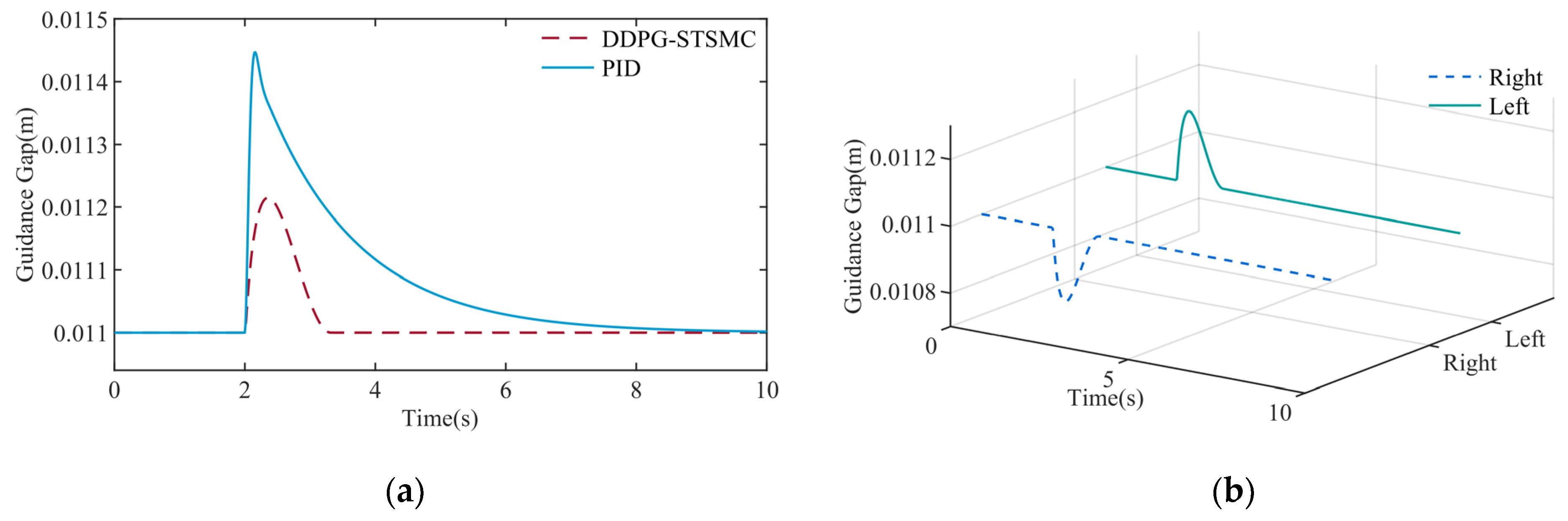
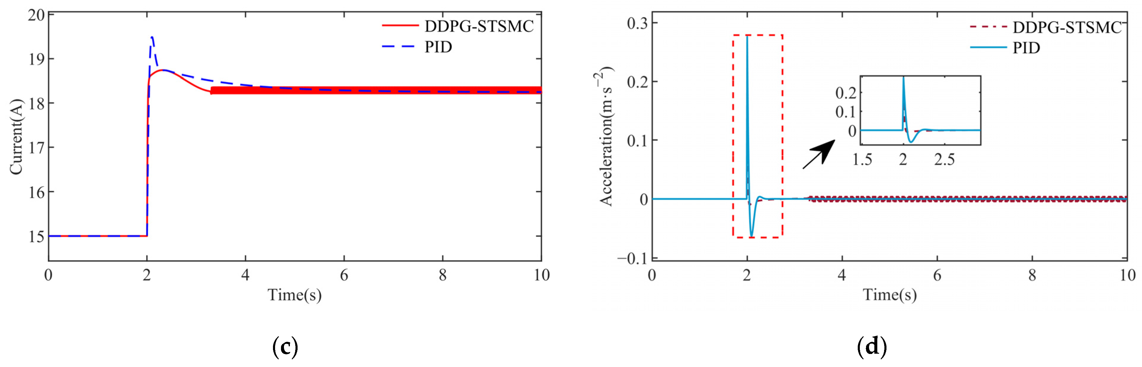
The step signal is introduced to simulate the typical working condition encountered in the operation of the guidance system: continuous crosswind interference. The step interference of 1 kN is applied at 2 s, and the control performance of the two controllers is compared. The control performance of the two controllers is as shown in
Figure 6. It can be seen that DDPG-STSMC achieved 60.4% lower gap overshoot, 16.14% lower current peak, 32.14% lower acceleration and achieved a significantly faster dynamic recovery rate compared to the conventional PID controller as shown in
Table 3.
5.2.3. Simulation of Pulse Excitation
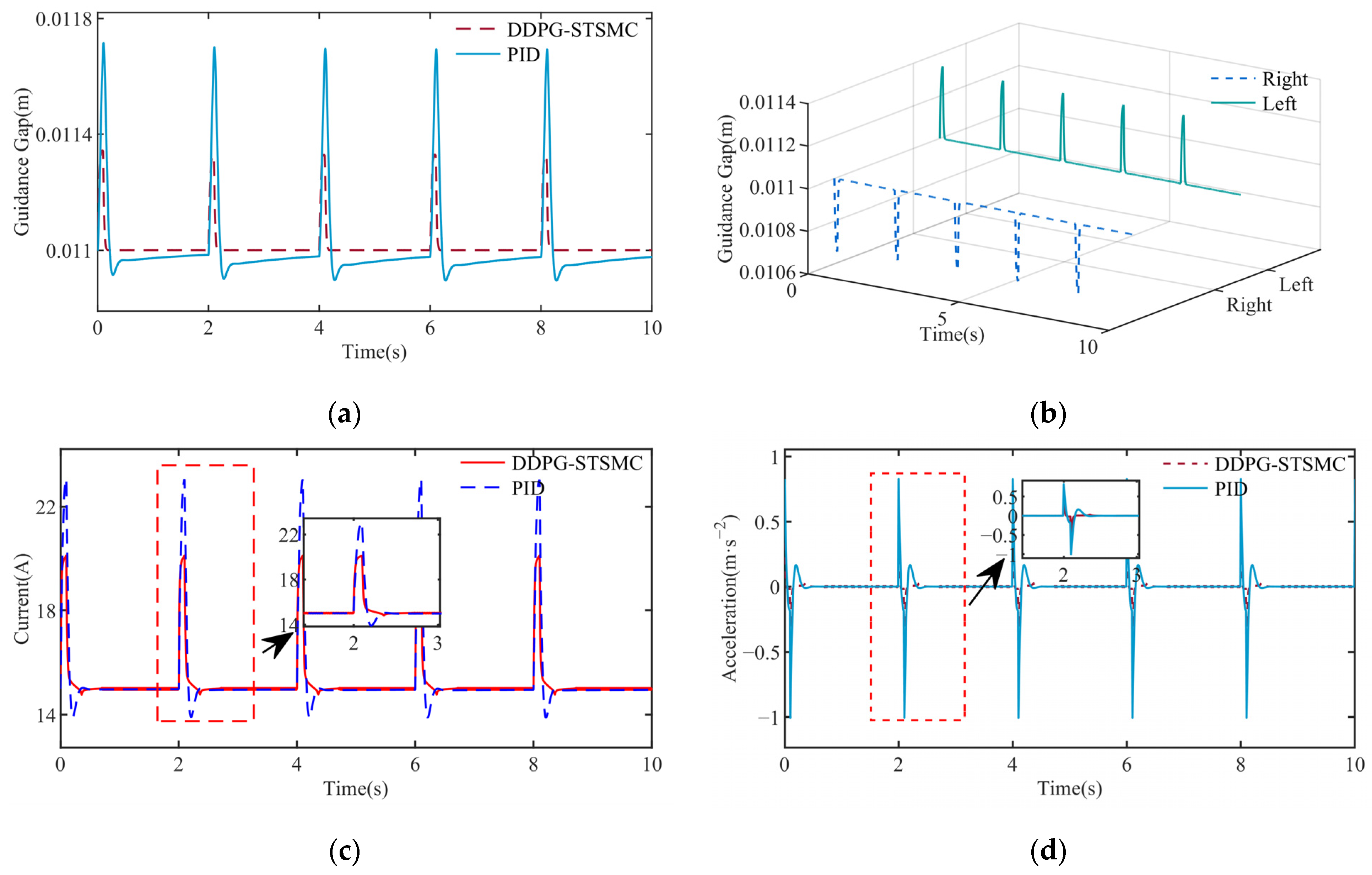
In order to simulate the instantaneous impact that the guidance unit may be subjected to, the system is subjected to pulse excitation every 2 s, and the pulse excitation size is 3000 N. The control performance of the two controllers is as shown in
Figure 7. It can be seen that DDPG-STSMC achieved 52.86% lower gap overshoot, 34.61% lower current peak, and 40.59% lower acceleration compared to PID. The specific comparison is shown in
Table 4.
5.2.4. Simulation of Track Irregularity Interference
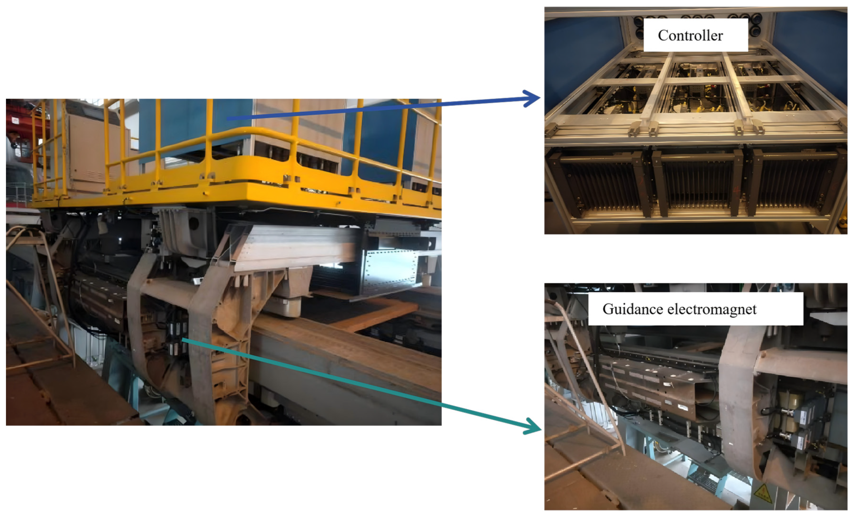
Track irregularity is formed by the superposition of various random factors such as construction accuracy deviation and operation wear, and its spatial distribution has random statistical characteristics. In this paper, based on the statistical law of track irregularity, the parametric design of random interference is carried out. The random excitation process of track irregularity to guide system is simulated by random interference to compare the control performance of different controllers under track irregularity. Tongji University operates a normal-conducting high-speed maglev test line. This test line comprises straight sections, transition curves, and circular curves. Furthermore, the university possesses a single-bogie test rig. This infrastructure provides the necessary hardware foundation for validating the control performance of the maglev guidance system under various operating conditions. The actual photograph of the experimental test bench is as shown in
Figure 8. In the simulation, with reference to the actual layout of Tongji University’s maglev test line, a disturbance with an amplitude of 3 mm was introduced to the guidance control unit. Additionally, to evaluate the control performance under deteriorating conditions, a further disturbance with an amplitude of 6 mm is applied.
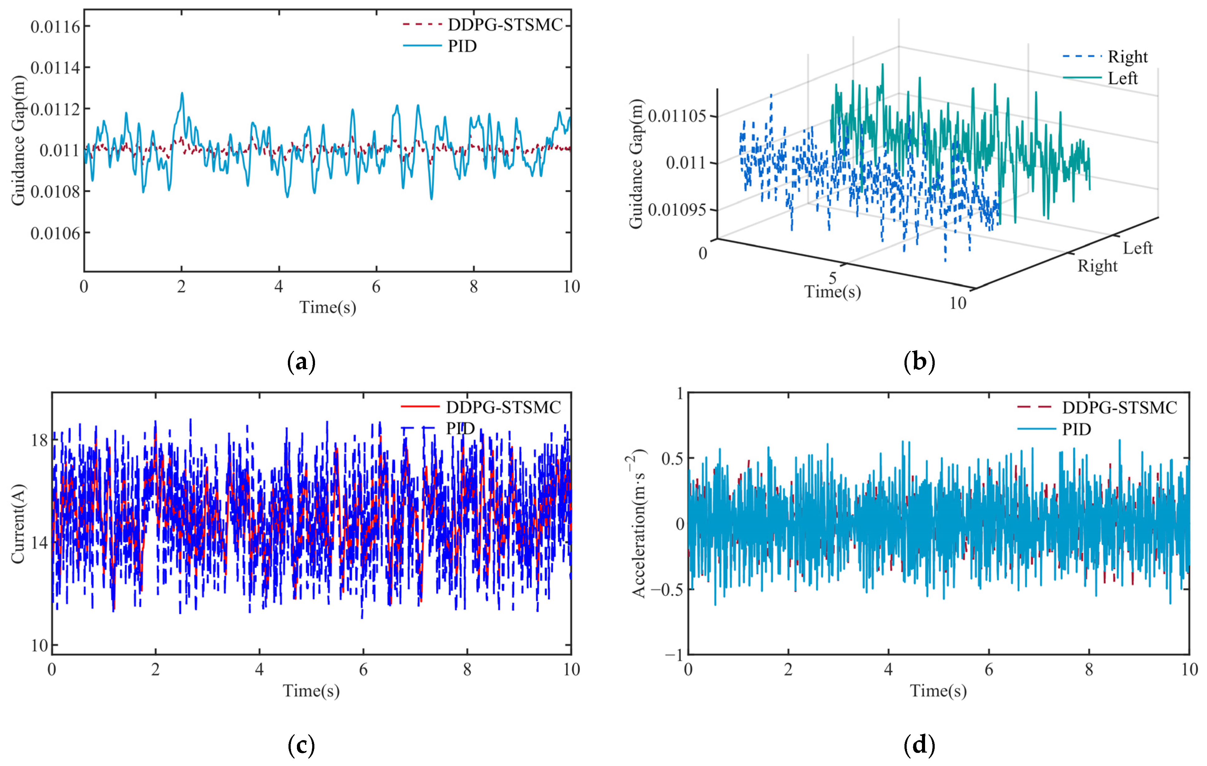
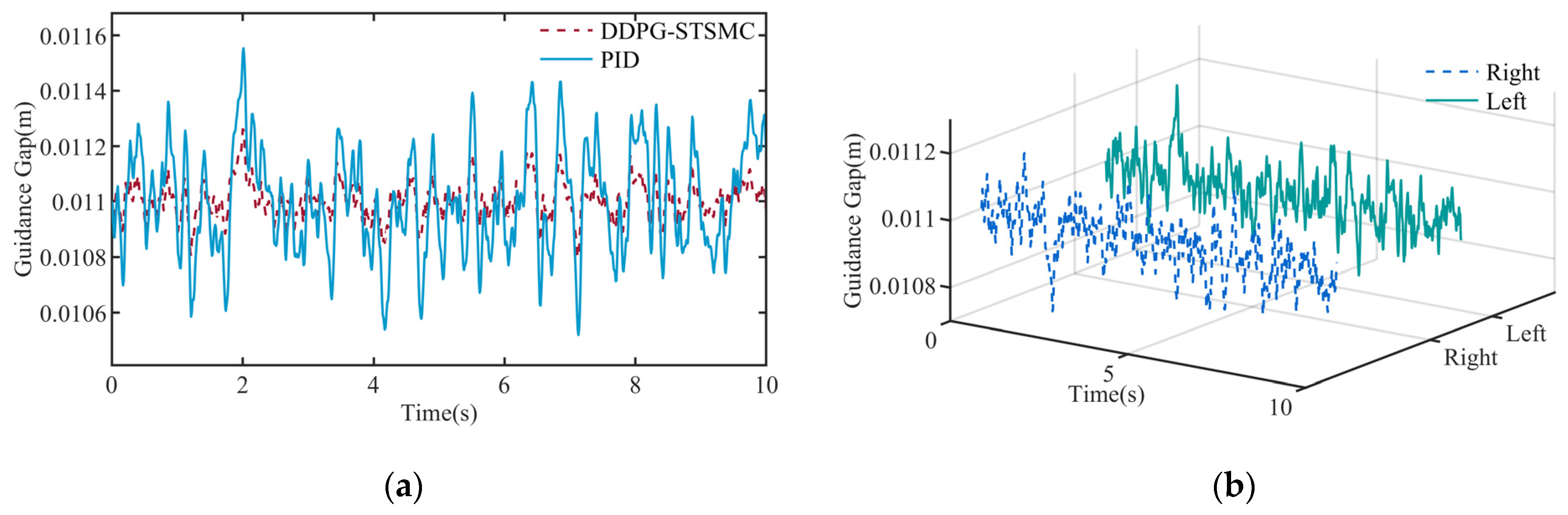
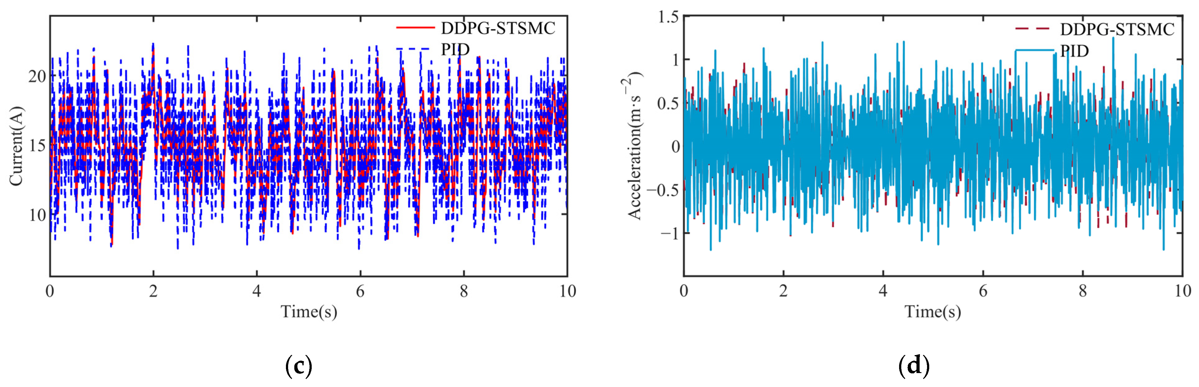
The simulation results of the two controllers under 3 mm and 6 mm irregularity disturbances are shown in
Figure 9 and
Figure 10, respectively. Through simulation, it can be concluded that the guide control performance of the DDPG-STSMC controller electromagnet is obviously improved, and the guide gap is basically stable at 11 mm. The change in guidance gap is far less than that of the PID controller. In terms of current response, the current fluctuation of DDPG-STSMC under two working conditions is 26.80% and 16.29% smaller than that of the PID controller, respectively. The peak acceleration of DDPG-STSMC is 23.81% and 19.17% smaller than that of PID controller. The specific data are shown in
Table 5.
6. Discussion
This paper addresses the challenges of strong nonlinearity and parameter time-variation in the high-speed maglev train guidance system by proposing a DDPG-STSMC control method that integrates the DDPG algorithm with STSMC. Through simulations under various typical operating conditions (e.g., periodic disturbances, step disturbances, and pulse excitations), it is demonstrated that the proposed STSMC algorithm incorporated with DDPG exhibits remarkable superiority in enhancing the control performance of the maglev train guidance system. Compared with the conventional PID controller, the proposed method achieves significant reductions in the overshoot, settling time, and steady-state error of the guidance gap, while simultaneously mitigating fluctuations in the guidance current and acceleration across different operating scenarios. These improvements indicate that the proposed method further augments the stability of the guidance gap, disturbance rejection capability, and dynamic response speed relative to the PID controller. Conventional PID controllers depend on fixed parameters and manual parameter calibration, whereas the DDPG-STSMC controller enables adaptive tuning of STSMC parameters through interactions between the agent and the guidance system, coupled with a tailored multi-objective hybrid reward function, thereby furnishing an efficient intelligent control paradigm for addressing this critical issue. From the perspective of engineering applications, this study establishes a theoretical foundation for subsequent hardware experiments via simulations under multiple representative operating conditions.
The research on high-speed maglev guidance control has undergone evolutionary stages, including robust control and 2-DOF control, all of which rely on precise mathematical modeling and manual parameter tuning. In contrast, the DDPG-STSMC method proposed herein leverages the model-free adaptive capability of DRL, empowering the agent to autonomously learn the optimal parameter matching relationship via interactions with the environment. In comparison with alternative control strategies such as Active Disturbance Rejection Control (ADRC) and adaptive Sliding Mode Control (SMC), the STSMC method—a representative second-order sliding mode technique—offers several core advantages. It eliminates the need for high-gain observers and suppresses the chattering phenomenon inherent in traditional SMC by designing a continuous control law. This renders it more suitable for high-speed maglev systems characterized by parameter time-variation and uncertain disturbances. Compared with other intelligent control methodologies, this study innovatively combines DDPG with STSMC. This hybrid framework combines reinforcement learning with Super-Twisting Sliding Mode Control, leveraging the advantages of both approaches while incorporating the practical operational priorities of the guidance system, thereby enabling more targeted and refined parameter optimization. In the proposed structure, STSMC serves as the underlying deterministic control backbone, which guarantees closed-loop stability across different operating points. To further improve robustness and generalization, diversified state perturbations derived from typical maglev guidance operating conditions are introduced during the training phase. Through exposure to multi-scenario disturbances, the agent learns gain adjustment strategies that preserve desirable dynamic response characteristics under varying conditions, thus enhancing the controller’s generalization capability. Future research may incorporate supplementary factors, such as the influence of guidance force degradation induced by eddy current effects in electromagnetic coils on control performance. Furthermore, while this study validates the guidance control system through simulations with diverse excitation signals, it fails to comprehensively encompass all uncertainties encountered in real-world operations. Consequently, additional HIL verification on physical test benches is imperative to further investigate the performance and robustness of the control method in actual physical systems.
In summary, the STSMC method integrated with DRL overcomes the inherent limitations of conventional control methods and provides an intelligent control solution for the maglev train guidance system. Through extensive simulation validation, this study also reduces the risk of trial and error and clarifies the key optimization direction for subsequent experiments which lay a robust theoretical foundation for future HIL experiments.
7. Conclusions
In this paper, a Super-Twisting Sliding Mode Control method combined with reinforcement learning is proposed for the high-speed maglev guidance system. By combining the Deep Deterministic Policy Gradient (DDPG) algorithm and the Super-Twisting Sliding Mode Control (STSMC), a multi-objective reward function integrating sliding mode surface convergence, gap stability and chattering suppression is constructed. The intelligent self-tuning of the Super-Twisting Sliding Mode Control parameters is achieved, and the stability of the closed-loop system is proved based on the Lyapunov theory at the theoretical level. The control method realizes the fast and accurate convergence of the guidance gap in a finite time and greatly reduces the gap fluctuation of the guidance system. Through simulation comparison under different typical working conditions, it is concluded that the DDPG-STSMC controller proposed in this paper can effectively shorten the adjustment time and reduce the guidance gap fluctuation compared with the traditional PID controller, thereby proving the effectiveness and robustness of the proposed control method. In this study, the core performance and engineering potential of the proposed control method are verified by simulating the typical working conditions and interference types in actual operation, which offers solid theoretical pre-research and feasibility verification for the engineering application of the control strategy of the maglev guidance system. Based on the simulation conclusions of this paper, the hardware-in-the-loop experiment will be carried out in the future to further verify the effectiveness and reliability of the control method in the real environment.
Author Contributions
Conceptualization, J.X. and C.C.; methodology, W.W.; software, W.W.; validation, J.X., W.W. and L.R.; formal analysis, C.C. and L.R.; investigation, J.X.; resources, J.X.; data curation, J.X.; writing—original draft preparation, W.W.; writing—review and editing, C.C.; visualization, W.J.; supervision, Z.G. and L.R.; project administration, L.R.; funding acquisition, J.X. All authors have read and agreed to the published version of the manuscript.
Funding
National Natural Science Foundation of China, grant number 52502449; National Natural Science Foundation of China, grant number 52232013; National Key R&D Program of China, grant number 2023YFB4302502; the China National Railway Group Science and Technology Program, grant number K2024T005.
Institutional Review Board Statement
Not applicable.
Informed Consent Statement
Not applicable.
Data Availability Statement
The data presented in this study are available on request from the corresponding author.
Acknowledgments
The authors would thank the National Maglev Transportation Engineering R&D Center for the support of the research.
Conflicts of Interest
The authors declare no conflicts of interest.
Abbreviations
The following abbreviations are used in this manuscript:
| DDPG | Deep Deterministic Policy Gradient |
| STSMC | Super-Twisting Sliding Mode Control |
| PID | Proportional–Integral–Derivative |
| DOF | Degree-of-Freedom |
| DRL | Deep Reinforcement Learning |
References
- Zhao, C. Research on Guidance Dynamics of EMS High-Speed Maglev Train; National University of Defense Technology: Changsha, China, 2014. [Google Scholar]
- Li, B.; Zhao, C.; Li, X.; Long, Z. Dynamics Modeling Analysis and Experiment of the Guidance Control System of High-Speed Maglev Train. IEEE Access 2020, 8, 206207–206221. [Google Scholar] [CrossRef]
- Hao, A.; She, L.; Chang, W. Adaptive Controller Design of Guidance System of EMS High Speed Maglev Train. Control. Eng. China 2008, 15, 116–119,170. [Google Scholar]
- Chang, W.; Hao, A.; Long, Z. Design of the Robust Controller of the Guidance System in High-Speed Maglev Train. Tiedao Xuebao/J. China Railw. Soc. 2008, 30, 40–45. [Google Scholar]
- Chang, W.; Hao, A.; Long, Z. Guidance Controller Design of High Speed Maglev Train Considering Random Irregularity of Guideway. J. Syst. Simul. 2008, 20, 6234–6237. [Google Scholar]
- Wu, Y. Guidance Control System and Simulation Research of EMS Type High-Speed Maglev Vehicle. Heilongjiang Keji Xueyuan Xuebao (J. Heilongjiang Inst. Sci. Technol.) 2006, 16, 244–247. [Google Scholar]
- Wu, Y. Simulation Research on Guidance Control System of High-Speed Maglev Train; Southwest Jiaotong University: Chengdu, China, 2006. [Google Scholar]
- Zhai, M. Research on the Active Guidance Control System in High Speed Maglev Train. IEEE Access 2019, 7, 741–752. [Google Scholar] [CrossRef]
- Piao, M.; Liang, S.; Xue, S.; Zhao, W. 2-Dof Control of Active Levitation and Guidance in High-Speed Maglev Train. Zhongguo Tiedao Kexue/China Railw. Sci. 2006, 27, 80–85. [Google Scholar]
- Zuo, Z. Research on Fault Tolerant Control of Guidance System of High Speed Maglev Train; National University of Defense Technology: Changsha, China, 2019. [Google Scholar]
- Wang, Z.; Guo, W.; Sang, Z.; Li, B.; Long, Z.; Li, X. Optimized Control Method for Guidance System of High-Speed Maglev Train. Xinan Jiaotong Daxue Xuebao/J. Southwest Jiaotong Univ. 2025, 60, 833–841, 864. [Google Scholar] [CrossRef]
- Li, B. Research on Optimal Control Algorithm for Active Guidance System for High Speed Maglev Train; National University of Defense Technology: Changsha, China, 2021. [Google Scholar]
- Kim, M.; Jeong, J.-H.; Lim, J.; Kim, C.-H.; Won, M. Design and Control of Levitation and Guidance Systems for a Semi-High-Speed Maglev Train. J. Electr. Eng. Technol. 2017, 12, 117–125. [Google Scholar] [CrossRef]
- Kim, C.; Ha, C.; Lim, J.; Han, H.; Kim, K. Yaw Motion Control of Electromagnetic Guidance System for High-Speed Maglev Vehicles. J. Electr. Eng. Technol. 2016, 11, 1299–1304. [Google Scholar] [CrossRef]
- Chen, C.; Xu, J.; Yang, J.; Gao, D.; Xu, Z. Dynamic analysis of high-speed maglev magnetic coupling and experimental study on vehicle-bridge characteristics. J. Vib. Control. 2025. [Google Scholar] [CrossRef]
- Chen, C.; Xu, J.; Rong, L.; Ji, W.; Lin, G.; Sun, Y. Neural-Network-State-Observation-Based Adaptive Inversion Control Method of Maglev Train. IEEE Trans. Veh. Technol. 2022, 71, 3660–3669. [Google Scholar] [CrossRef]
- Khalil, H.K. Nonlinear Systems, 3rd ed.; Pearson: London, UK, 2001. [Google Scholar]
- Hu, W.; Yang, Y.; Liu, Z. Deep Deterministic Policy Gradient (DDPG) Agent-Based Sliding Mode Control for Quadrotor Attitudes. Drones 2024, 8, 95. [Google Scholar] [CrossRef]
- Wang, Z.; Yang, S.; Xie, T.; Tong, J.; Hao, W. Trajectory Planning of Quadrotor Elastic Suspension System Based on DDPG Algorithm. ISA Trans. 2025, 167, 2063–2077. [Google Scholar] [CrossRef] [PubMed]
- Lu, Z.; Wei, J.; Wang, Z. Active Steering Control for Independently Rotating Wheels Driven by PMSMs Based on the Improved DDPG Algorithm. J. Mech. Sci. Technol. 2025, 39, 2113–2126. [Google Scholar] [CrossRef]
- Jin, L.; Yang, S. Fault-Tolerant Control of Spacecraft Attitude with Prescribed Performance Based on Reinforcement Learning. Beijing Hangkong Hangtian Daxue Xuebao/J. Beijing Univ. Aeronaut. Astronaut. 2024, 50, 2404–2412. [Google Scholar] [CrossRef]
- Liang, Y. Reinforcement Learning Control Fora Magnetic Levitation System; Harbin University of Technology: Harbin, China, 2019. [Google Scholar]
- Ma, L.; Qi, M.; Chen, S.; Bian, H.; Zhang, J. Optimization of Underactuated Ship Sliding Mode Controller Based on the DDPG Algorithm. J. Mar. Sci. Technol. 2025, 33, 160–168. [Google Scholar] [CrossRef]
- Brockett, R. Poles, Zeros, and Feedback: State Space Interpretation. IEEE Trans. Autom. Control. 1965, 10, 129–135, Correction in IEEE Trans. Autom. Control. 1965, 10, 460. [Google Scholar] [CrossRef]
Figure 1.
Overlapping system diagram.
Figure 1.
Overlapping system diagram.
Figure 2.
The schematic diagram of the equivalent model of the single-ended guidance system.
Figure 2.
The schematic diagram of the equivalent model of the single-ended guidance system.
Figure 3.
Deep Deterministic Policy Gradient (DDPG) algorithm block diagram.
Figure 3.
Deep Deterministic Policy Gradient (DDPG) algorithm block diagram.
Figure 4.
Agent training curve.
Figure 4.
Agent training curve.
Figure 5.
(a) Comparison of gap response of two controllers; (b) DDPG-STSMC controls the guidance gap on both sides; (c) comparison of the current response of the two controllers; (d) comparison of acceleration response of two controllers.
Figure 5.
(a) Comparison of gap response of two controllers; (b) DDPG-STSMC controls the guidance gap on both sides; (c) comparison of the current response of the two controllers; (d) comparison of acceleration response of two controllers.
Figure 6.
(a) Comparison of gap response of two controllers; (b) DDPG-STSMC controls the guidance gap on both sides; (c) comparison of the current response of the two controllers; (d) comparison of acceleration response of two controllers.
Figure 6.
(a) Comparison of gap response of two controllers; (b) DDPG-STSMC controls the guidance gap on both sides; (c) comparison of the current response of the two controllers; (d) comparison of acceleration response of two controllers.
Figure 7.
(a) Comparison of gap response of two controllers; (b) DDPG-STSMC controls the guidance gap on both sides; (c) comparison of the current response of the two controllers; (d) comparison of acceleration response of two controllers.
Figure 7.
(a) Comparison of gap response of two controllers; (b) DDPG-STSMC controls the guidance gap on both sides; (c) comparison of the current response of the two controllers; (d) comparison of acceleration response of two controllers.
Figure 8.
High-speed maglev single levitation frame test bench.
Figure 8.
High-speed maglev single levitation frame test bench.
Figure 9.
(a) Comparison of gap response of two controllers; (b) DDPG-STSMC controls the guidance gap on both sides; (c) comparison of the current response of the two controllers; (d) comparison of acceleration response of two controllers.
Figure 9.
(a) Comparison of gap response of two controllers; (b) DDPG-STSMC controls the guidance gap on both sides; (c) comparison of the current response of the two controllers; (d) comparison of acceleration response of two controllers.
Figure 10.
(a) Comparison of gap response of two controllers; (b) DDPG-STSMC controls the guidance gap on both sides; (c) comparison of the current response of the two controllers; (d) comparison of acceleration response of two controllers.
Figure 10.
(a) Comparison of gap response of two controllers; (b) DDPG-STSMC controls the guidance gap on both sides; (c) comparison of the current response of the two controllers; (d) comparison of acceleration response of two controllers.
Table 1.
Guidance system controller related parameters.
Table 1.
Guidance system controller related parameters.
| Symbolic | Physical Meaning | Numerical Value |
|---|
| Vacuum permeability | |
| Number of turns of coil winding | 200 |
| Electromagnet magnetic pole area | 0.021 |
| Coil winding resistance | 2.79 |
| Balance point gap | 11 |
| Balance point working current | 15 |
| The equivalent inductance of the electromagnet coil | 0.17 |
| Quality of guide electromagnet | 390 |
| The equivalent mass of a guide unit | 1540 |
Table 2.
Comparison of control effect under periodic disturbance.
Table 2.
Comparison of control effect under periodic disturbance.
| Performance Index | DDPG-STSMC | PID | Control Optimization Effect |
|---|
| Gap change amplitude/mm | 0.17 | 0.39 | 56.41% |
| Current change amplitude/A | 4.16 | 4.66 | 10.73% |
| Acceleration peak/m·s−2 | 0.12 | 0.16 | 25.00% |
Table 3.
Comparison of control effect under step disturbance.
Table 3.
Comparison of control effect under step disturbance.
| Performance Index | DDPG-STSMC | PID | Control Optimization Effect |
|---|
| Gap change amplitude/mm | 0.21 | 0.45 | 60.40% |
| Current change amplitude/A | 3.74 | 4.46 | 16.14% |
| Acceleration peak/m·s−2 | 0.19 | 0.28 | 32.14% |
Table 4.
Comparison of control effect under pulse interference.
Table 4.
Comparison of control effect under pulse interference.
| Performance Index | DDPG-STSMC | PID | Control Optimization Effect |
|---|
| Gap change amplitude/mm | 0.33 | 0.7 | 52.86% |
| Current change amplitude/A | 5.12 | 7.83 | 34.61% |
| Acceleration peak/m·s−2 | 0.6 | 1.01 | 40.59% |
Table 5.
(a) Comparison of control effect of guidance gap under different amplitude irregularity interference. (b) Comparison of control effect of current response under different amplitude irregularity interference. (c) Comparison of control effect of current response under different amplitude irregularity interference.
Table 5.
(a) Comparison of control effect of guidance gap under different amplitude irregularity interference. (b) Comparison of control effect of current response under different amplitude irregularity interference. (c) Comparison of control effect of current response under different amplitude irregularity interference.
| (a) |
| Irregularity interference amplitude/mm | Gap change peak of DDPG-STSMC controller/mm | Gap change peak of PID controller/mm | Control effect optimization |
| 3 | 0.08 | 0.28 | 71.43% |
| 6 | 0.26 | 0.55 | 52.73% |
| (b) |
| Irregularity interference amplitude/mm | Current change peak of DDPG-STSMC controller/A | Current change peak of PID controller/A | Control effect optimization |
| 3 | 2.84 | 3.88 | 26.8% |
| 6 | 6.27 | 7.49 | 16.29% |
| (c) |
| Irregularity interference amplitude/mm | Peak acceleration of DDPG-STSMC controller/m·s−2 | Peak acceleration of PID controller/m·s−2 | Control effect optimization |
| 3 | 0.48 | 0.63 | 23.81% |
| 6 | 0.97 | 1.20 | 19.17% |
| Disclaimer/Publisher’s Note: The statements, opinions and data contained in all publications are solely those of the individual author(s) and contributor(s) and not of MDPI and/or the editor(s). MDPI and/or the editor(s) disclaim responsibility for any injury to people or property resulting from any ideas, methods, instructions or products referred to in the content. |




 ,
,