1. Introduction
Limit switches are electromechanical components widely used for position detection and motion control in construction machinery, marine equipment, and industrial automation systems. Under conventional operating conditions, limit switches typically operate at ampere-level currents and are therefore classified as high-current switching devices. However, in special applications requiring explosion protection—such as dusty workshops, underground mines, fuel depots, and hazardous shipboard zones—position detection circuits must comply with intrinsically safe (IS) design principles. In these cases, the allowable load current is strictly limited to only a few milliamperes or several tens of milliamperes, forcing the limit switches to operate under micro-current conditions. A representative example is shipborne electromechanical equipment installed in explosion-proof areas, where the operating current of snap-action limit switches is often restricted to the milliampere range.
In practical applications, shipborne limit switches operating under micro-current loads exhibit a high incidence of triggering failures when exposed to hot–humid and salt-laden marine environments. These failures are typically characterized by intermittent and random malfunction events, in which the moving and stationary contacts fail to conduct electrically after mechanical engagement. Notably, unlike conventional switch failures, no obvious mechanical damage, severe corrosion, or open-circuit faults are observed on the contact components, indicating that the failure is dominated by abnormal electrical contact behavior rather than mechanical degradation. Such abnormal triggering behavior can seriously impair the reliability of position detection systems and, in severe cases, threaten the operational safety of shipboard equipment. Therefore, elucidating the root causes and intrinsic failure mechanisms of micro-current limit switches in marine environments is of significant practical importance.
Extensive research has been conducted on switch-type electrical components, including limit switches and snap-action microswitches, covering reliability assessment, fault diagnosis, structural optimization, and electrical contact material modification. In the field of reliability analysis, Mulloni et al. [
1] systematically investigated instability phenomena in MEMS switches induced by fabrication errors, mechanical deformation, contact wear, and temperature variations, highlighting the multifactorial nature of reliability degradation. Zhou et al. [
2] employed multiphysics coupled simulations to analyze the influence of structural and material parameters on system reliability. Zarei et al. [
3] proposed a stochastic nonlinear Wiener-process-based reliability model to describe multisource degradation in relays, which was validated experimentally. Yang et al. [
4] conducted high-temperature accelerated degradation tests to study the evolution of contact pressure and resistance in relay reeds, while Wen et al. [
5] revealed fretting wear mechanisms through vibration experiments and established a correlation model between contact resistance and closure characteristics. These studies provide important insights into the reliability evolution of switching devices under conventional operating conditions; however, they are predominantly conducted under medium- or high-current regimes and do not explicitly address the failure behavior of limit switches operating under micro-current loads in corrosive marine environments.
In terms of fault diagnosis, research efforts have focused on diagnostic methodologies, fault mechanism identification, and system-level optimization strategies. Wang et al. [
6] proposed a fuzzy-logic-based fault diagnosis method for fault-tolerant drive systems, enabling accurate detection of intermittent open-circuit faults. Shahbazi et al. [
7] developed an open-switch fault diagnosis algorithm for power electronic interfaces, successfully identifying failures induced by limit switch malfunctions in wind energy systems. Current- and voltage-based diagnostic approaches have also been widely reported [
8,
9,
10,
11], while entropy-based signal processing techniques have demonstrated effectiveness in detecting open-circuit faults in motor inverter systems [
12,
13]. However, these studies primarily aim at fault detection and identification at the system or signal level, rather than eliminating the root causes of contact failure, and therefore do not directly address the reliability degradation of limit switches operating under micro-current conditions in harsh marine environments.
From a structural perspective, the electrical contact system plays a decisive role in the performance and reliability of contact-type switches and has therefore attracted considerable attention. Various studies have explored structural optimization strategies to improve contact stability, durability, and response characteristics [
14,
15,
16,
17,
18,
19]. In parallel, extensive research has been devoted to electrical contact materials, particularly silver-based composites, with the aim of enhancing arc erosion resistance and electrical stability under medium- and high-current conditions [
20,
21,
22,
23]. Nevertheless, most existing structural and material optimization strategies are developed for medium- and high-current applications, where arc erosion and severe mechanical wear dominate the failure process. Under micro-current conditions, especially in marine environments, insufficient arc energy fundamentally alters the failure mechanism, rendering these approaches inadequate for suppressing heterogeneous film accumulation and contact resistance instability.
A comprehensive review of the literature reveals that most existing studies have focused on high-current operating regimes, while the failure behavior of limit switches under micro-current conditions remains fundamentally different and insufficiently explored. In marine environments, micro-current limit switches exhibit a distinctive triggering failure mode that cannot be explained by conventional arc erosion or wear-dominated mechanisms. Research specifically addressing the failure mechanisms of micro-current limit switches in marine hot–humid and salt spray environments is scarce, and systematic investigations remain largely absent.
In this study, the triggering failure of shipborne micro-current snap-action limit switches operating in marine hot–humid salt spray environments is systematically investigated from the perspectives of electrical contact behavior, environmental degradation, and structural response. By combining electrical performance characterization, accelerated environmental exposure tests, and in situ microscopic analysis of contact surfaces, the failure mechanism dominated by corrosion product formation and contaminant migration is elucidated. The current-dependent electrical contact behavior is further clarified, demonstrating that under micro-current conditions, insufficient arc energy prevents effective disruption of high-resistance heterogeneous films, leading to their continuous accumulation and abnormal increases in contact resistance. Based on the identified film-dominated failure mechanism, and inspired by the natural self-cleaning behavior of crabs that remove contaminants through repetitive scraping motions, a biomimetic press-and-wipe self-cleaning dual-redundant limit switch structure is proposed. Unlike conventional sliding or wiping contact designs primarily intended to reduce contact resistance or improve corrosion resistance, the proposed structure is explicitly derived from the micro-current failure mechanism and enables active regulation of surface film evolution through controlled mechanical rubbing. Finally, comparative experiments conducted under simulated marine hot–humid and salt spray environments validate the effectiveness of the proposed design in suppressing heterogeneous film accumulation and maintaining stable electrical contact performance during long-term operation.
Overall, this work establishes a mechanism-driven framework linking failure characterization, electrical contact behavior, and biomimetic structural design. It provides both a scientific understanding of film-dominated micro-current failures and a practical engineering solution to ensure high-reliability operation of micro-current limit switches in harsh marine conditions.
3. Failure Mechanism Analysis of Triggering Failure Under Marine Environments
The above-mentioned snap-action limit switch is widely used in industrial automation, mechanical position limiting, and safety protection systems. In shipborne applications, these switches are typically installed on deck-mounted or near-deck equipment and operate in a marine environment characterized by high humidity, salt-laden air, and continuous low-frequency mechanical vibration. In addition, to meet intrinsic safety requirements, the switches usually operate under micro-current loads and are energized only during equipment operation, with frequent but short-duration actuation events.
Under such marine hot–humid and salt spray conditions, snap-action limit switches operating under micro-current loads are prone to triggering failure, which may further induce abnormal behavior of electromechanical equipment. The representative environmental and operational conditions considered in this study are summarized in
Table 1.
To systematically investigate the triggering failure of limit switches under micro-current loads in marine hot–humid salt spray environments, a series of experiments was conducted to progressively identify and verify the underlying causes. Voltage waveform measurements were first performed to characterize abnormal switching behavior and signal instability. Structural inspections and contact force tests were then carried out to determine whether mechanical damage or insufficient contact force contributed to the failures. Microscopic examination of internal contamination and subsequent chemical analysis of the contact surfaces clarified the composition and formation of heterogeneous films. Finally, current-gradient testing was employed to verify the decisive influence of the operating current on contact recovery and film removal. Together, these experiments establish a stepwise, validated understanding of the dominant failure mechanisms under the targeted marine micro-current operating conditions.
3.1. Voltage Signal Detection of Faulty Limit Switches
The voltage waveform during the switching process of a limit switch directly reflects the on–off state and stability of the electrical contacts, and therefore provides an effective means for identifying triggering failure characteristics.
For a new or healthy switch, the waveform should exhibit two stable voltage levels: a high level (Vmax), when the contacts are reliably open, and a near-zero level (Vmin) when they are firmly closed.
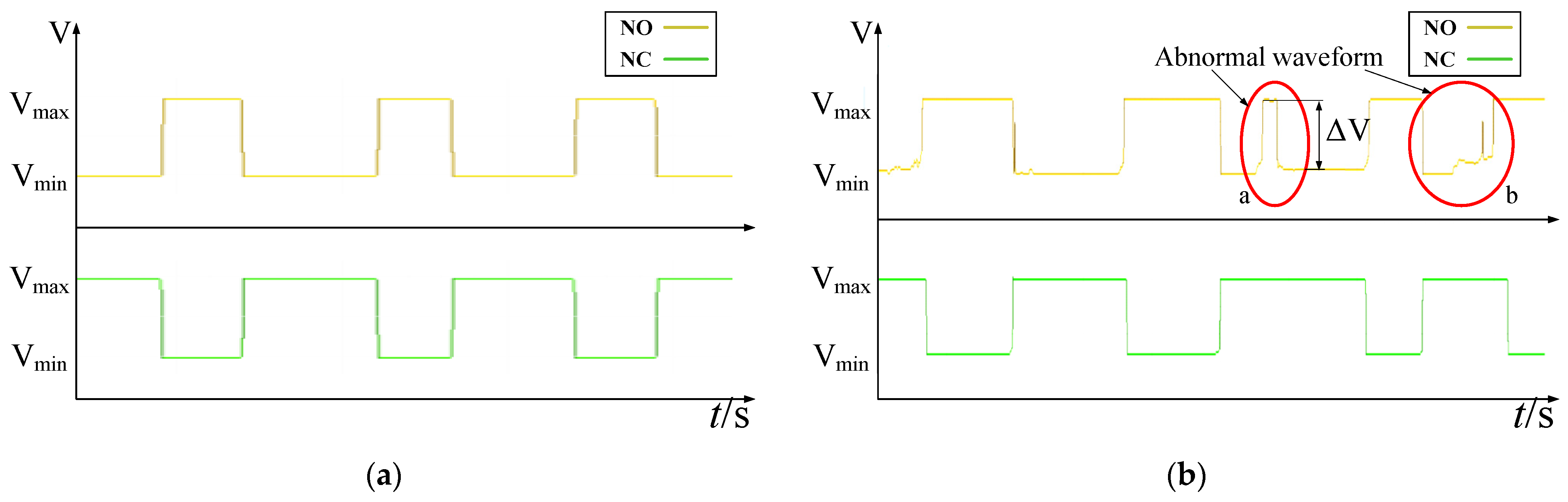
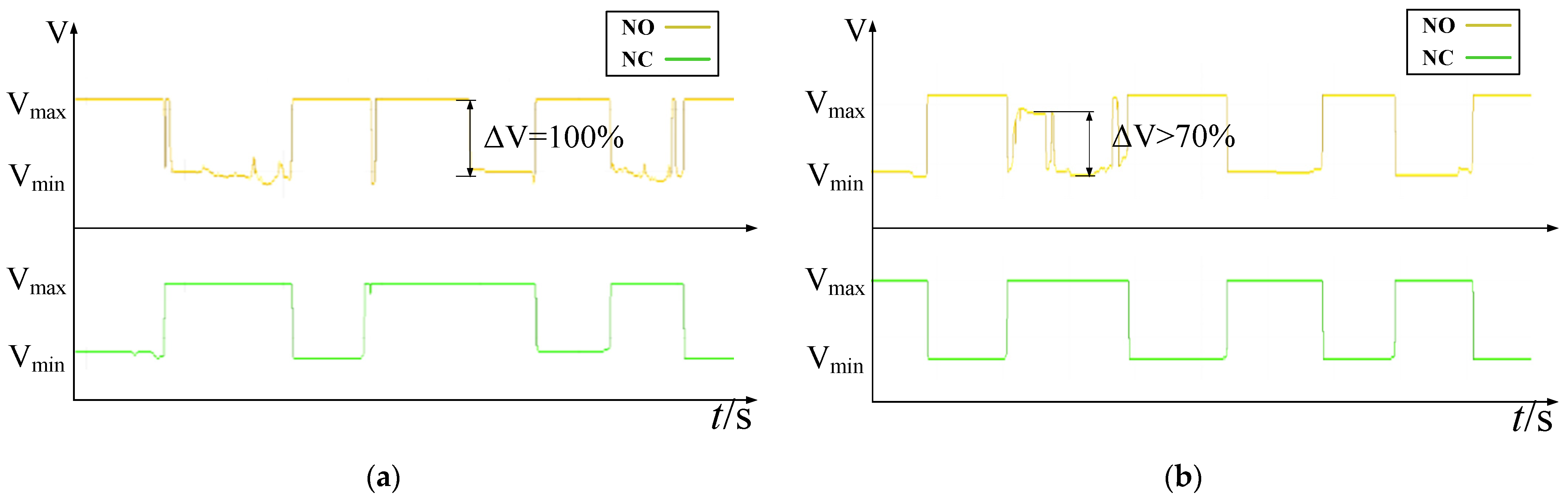
The switching voltage waveforms of a normally operating limit switch and a micro-current load limit switch after approximately 30 days of exposure to a marine hot–humid salt spray environment are shown in
Figure 2a and
Figure 2b, respectively.
Compared with the clean transitions in
Figure 2a, the voltage waveform in
Figure 2b exhibits abnormal behavior at positions a and b, characterized by pronounced fluctuations and voltage spikes. This behavior indicates instability of the normally open electrical contact during the closing phase. This indicates that the contact resistance is no longer stable and low—instead of reaching the ideal V
min, the voltage during closure shows erratic increases, reflecting intermittent high-resistance points or unstable contact mating.
Such instability during closure corresponds to a significant and volatile increase in the contact voltage drop (∆V) compared to the initial Vmin. Sustained operation under these conditions not only leads to incorrect control signal interpretation and unintended system responses, but the repeated abnormal switching also induces transient micro-arcing or localized discharge events at the contact interface. These events further accelerate the degradation of the electrical contacts through oxidation and erosion, increasing ∆V over time and ultimately progressing toward complete triggering failure, thereby posing clear risks to system reliability and operational safety.
3.2. Structural Condition Inspection of Faulty Limit Switches
To determine whether triggering failure under micro-current conditions originates from mechanical damage, the internal structural integrity of faulty limit switches exposed to marine salt spray environments was first examined.
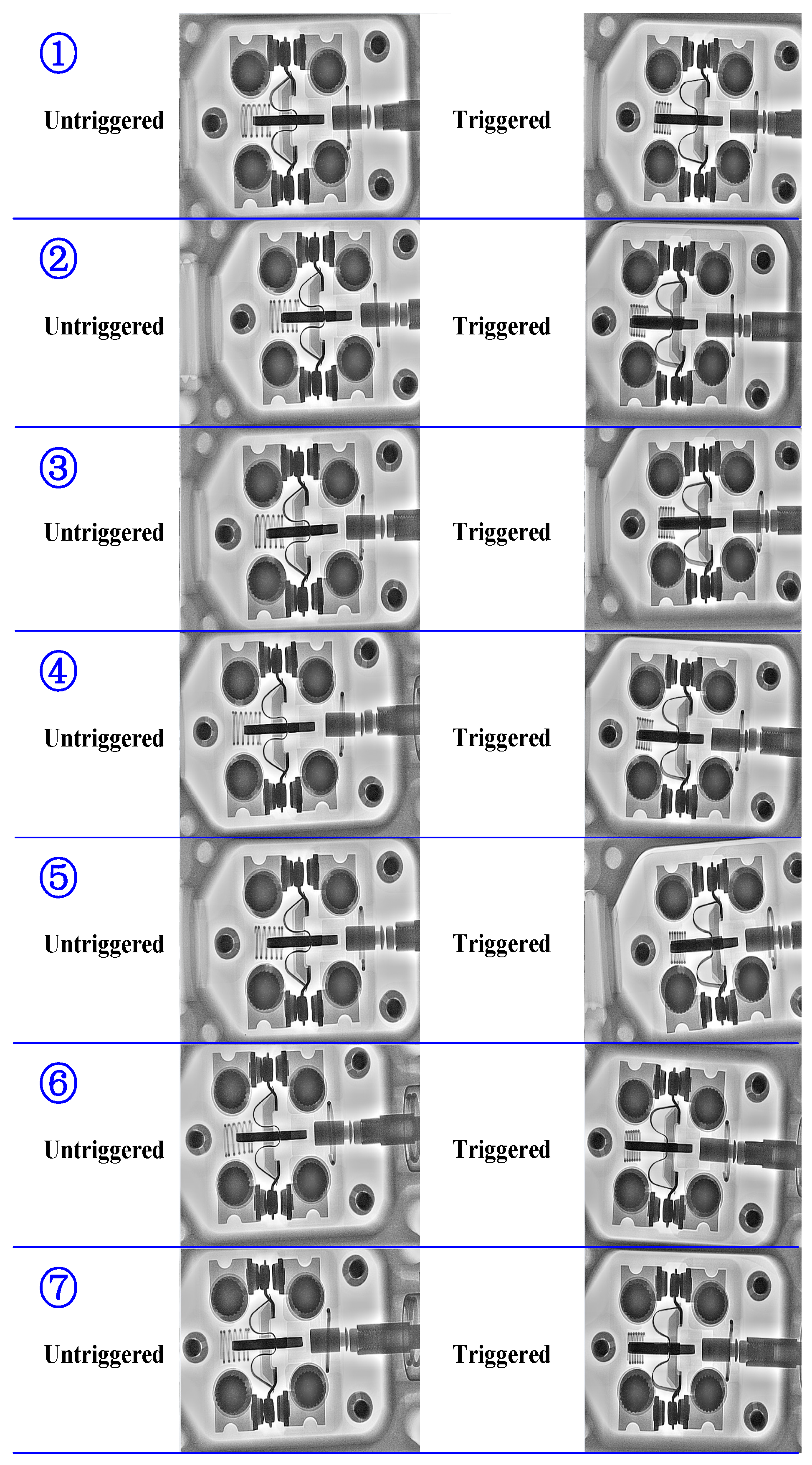
After removing the metal cover plates of seven faulty limit switches, X-ray in situ imaging was performed on each sample. Structural scans were conducted under both the triggered and non-triggered states to observe whether abnormalities existed within the microswitch units. The X-ray images of the faulty switches are shown in
Figure 3.
The results show that no structural damage was observed in any of the microswitch units. The moving electrical contacts exhibited normal motion behavior, and sufficient mechanical engagement between the moving and stationary electrical contacts was achieved in both operational states.
To further verify this observation, the contact forces of the microswitch units were measured in both free (non-triggered) and pressed (triggered) states. The free-state contact force corresponds to the normally closed electrical contact, whereas the pressed-state force corresponds to the normally open electrical contact. The test results are summarized in
Table 2.
As shown in
Table 2, the contact forces of all microswitch units are comparable and remain within the design specifications, with no significant abnormalities observed. Therefore, it can be concluded that the triggering failure of the investigated limit switches is not caused by internal mechanical damage or insufficient contact force.
3.3. Inspection of Internal Foreign Matter
In addition to mechanical factors, internal contamination may also contribute to triggering failure. If foreign matter adheres to the contact surfaces, the electrical contact resistance can increase significantly, thereby impairing switching stability.
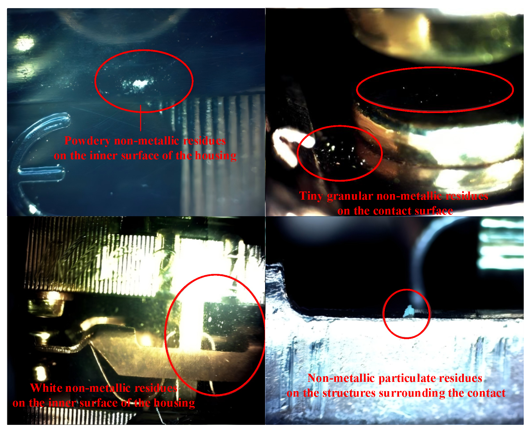
To assess the contamination status, the internal structures of the microswitch units were examined using electron microscopy. White non-metallic residues were observed to varying degrees on the inner housing surfaces, contact surfaces, and surrounding structural components of all faulty samples, as shown in
Figure 4.
For conventional Ag–Zn-based microswitches, electrical discharge during normal operation can induce migration and deposition of environmental or internal contaminants. Specifically, the static electric field and micro-arcs at the contact interface attract airborne or internally generated particles, which embed into the contact surface, forming a surface layer rich in C, N, and O compounds. Repetitive triggering of the contacts mechanically redistributes these contaminants. When the Au plating on the contact surface is worn, exposing the underlying Ag–Zn alloy, residual salts such as NaCl may react with Zn, forming ZnCl2 deposits. These phenomena represent the typical contamination evolution in conventional microswitches.
The presence of these residues poses a substantial risk to electrical contact stability. When located at the contact interface between the moving and stationary electrical contacts, such residues can directly obstruct reliable electrical conduction. Furthermore, mechanical vibration during switch actuation may promote dynamic migration of the residues, introducing additional uncertainty into the electrical conduction state. Therefore, internal foreign matter is considered a critical contributor to unstable electrical contact behavior and triggering failure.
3.4. Formation Mechanism of the Heterogeneous Film
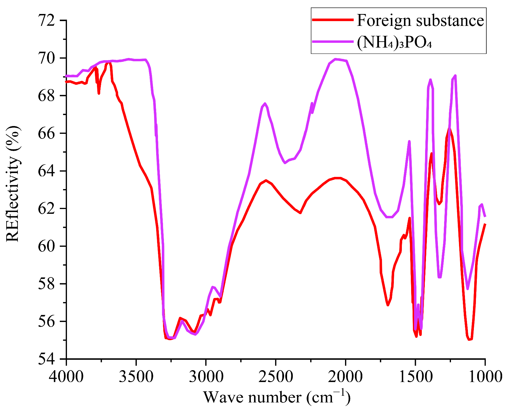
To determine whether the heterogeneous film observed in micro-current switches contains chemical components different from those formed during normal discharge in conventional switches, samples from the contact region were analyzed using Fourier transform infrared (FT-IR) spectroscopy. The FT-IR results, shown in
Figure 5, reveal that the primary component of the heterogeneous film is ammonium phosphate ((NH
4)
3PO
4), a white, water-soluble inorganic salt that readily deliquesces under humid conditions.
Further material analysis of the limit switch components showed no detectable phosphorus element in the base materials, excluding the possibility that ammonium phosphate originated from material degradation of the switch itself. In addition, disassembly inspections of new switches of the same model and batch revealed no presence of ammonium phosphate. Therefore, it is inferred that ammonium phosphate is formed during service, as moisture in the environment carries phosphorus- or ammonium-containing substances into the switch interior, where they react and crystallize. The hygroscopic nature of this substance under humid conditions is consistent with the proposed formation mechanism.
In summary, the heterogeneous film observed in micro-current limit switches can be regarded as a composite of two distinct contributions: (1) conventional C-, N-, and O-rich compounds along with ZnCl
2 deposits generated during normal operation of Ag–Zn-based switches through electrical discharge and contact wear; and (2) an additional ammonium phosphate layer formed specifically under humid marine conditions, as described in
Table 1. The FT-IR analysis provides clear chemical identification of this latter component, enabling differentiation from the typical discharge- and wear-induced deposits and supporting a unified understanding of the film formation and evolution mechanism.
3.5. Current-Gradient Testing
Notably, limit switches of identical structure operating under high-current loads (>2 A) in the same marine environment did not exhibit triggering failure, nor was any heterogeneous film observed, indicating a strong dependence on operating current.
To clarify the decisive influence of current magnitude on electrical contact performance, we designed and conducted a systematic current-gradient switching test. The test subjects were seven limit switches, all selected from the same faulty batch and confirmed to have heterogeneous films on their contacts. The test setup employed a constant current source with a pure resistive load, applying sequential currents of 0.2 A, 1 A, 2 A, and 5 A. At each current level, the switches were cycled at a rate of 10 cycles per minute (with a closed-state duration of ≥2 s per cycle). Each switch underwent 50 cycles per day for three days, resulting in a total of 150 switching cycles at each current level. We defined the quantitative criterion for functional recovery as the contact voltage drop (ΔV) stabilizing below 10% of its maximum initial value (i.e., a reduction of >90%) recorded at that current level.
The detailed test process for two representative faulty switches (No. 3 and No. 4) is shown in
Figure 6 and
Figure 7. At 0.2 A, persistent triggering failures were observed. When the current was increased to 1A, the failure frequency decreased markedly. Normal switching behavior was almost completely restored at 2 A and 5 A, with the contact voltage drop ΔV falling to very low levels.
To comprehensively evaluate the universality of the current effect,
Table 3 summarizes the functional recovery status of all seven tested switches at each current level. The recovery status was determined based on the aforementioned voltage-drop criterion combined with the success rate of triggering.
Post-test inspection of all switch contacts confirmed that the heterogeneous film had either disappeared or was significantly reduced on the contact surfaces of all switches that achieved complete functional recovery at currents of 2 A and above (“Post-test Contact Condition” in
Table 3). This stands in sharp contrast to the contact morphology of faulty switches that did not undergo the current test.
These results clearly demonstrate that current magnitude is a critical factor determining electrical contact performance. Under low current (0.2 A), the arc energy is insufficient to disrupt the insulating film. As the current increases, enhanced Joule heating and incipient arcing begin to degrade the film (manifested as partial recovery at 1 A). When the current reaches a threshold of approximately 2 A, the intense arc discharge generated upon contact closure provides sufficient thermal and electromagnetic effects to effectively remove the heterogeneous film from the contact surface, thereby reliably restoring stable metallic contact and electrical conduction.
3.6. Summary of Failure Mechanisms
The triggering failure of micro-current load limit switches in marine hot–humid salt spray environments can be attributed to the following mechanisms:
- (1)
Environmental ingress and heterogeneous film formation:
Moisture in marine environments transports phosphorus- or ammonium-containing substances into the switch interior, leading to the formation of heterogeneous films such as ammonium phosphate on the contact surfaces. These films obstruct electrical conduction at the contact interface and degrade switching stability.
- (2)
Insufficient self-cleaning capability under micro-current conditions:
Under micro-current loads, inadequate arc energy is generated during contact closure, preventing effective disruption or removal of the heterogeneous film. As a result, the film accumulates progressively, causing a continuous increase in contact resistance. This process forms a positive feedback loop that accelerates electrical contact degradation and exacerbates triggering failure.
4. Optimized Design Scheme
Considering the stringent requirements of explosion-proof operating environments, periodic removal of heterogeneous films on electrical contact surfaces by applying high currents is not feasible. Therefore, to ensure the long-term operational reliability of limit switches in marine hot–humid and salt spray environments, it is necessary to develop a novel limit switch capable of achieving effective electrical contact self-cleaning under micro-current load conditions.
The failed limit switches investigated in this study adopt a conventional snap-action contact configuration. In such structures, the relative sliding displacement between the moving and stationary electrical contacts during engagement is extremely limited. As a result, surface contaminants tend to be compacted rather than removed during impact, which facilitates the accumulation of heterogeneous films at the contact interface. To fundamentally mitigate contaminant accumulation and film formation, an optimized dual-redundant limit switch design incorporating a rubbing–pressing self-cleaning mechanism is proposed.
4.1. Biomimetic Design Concept
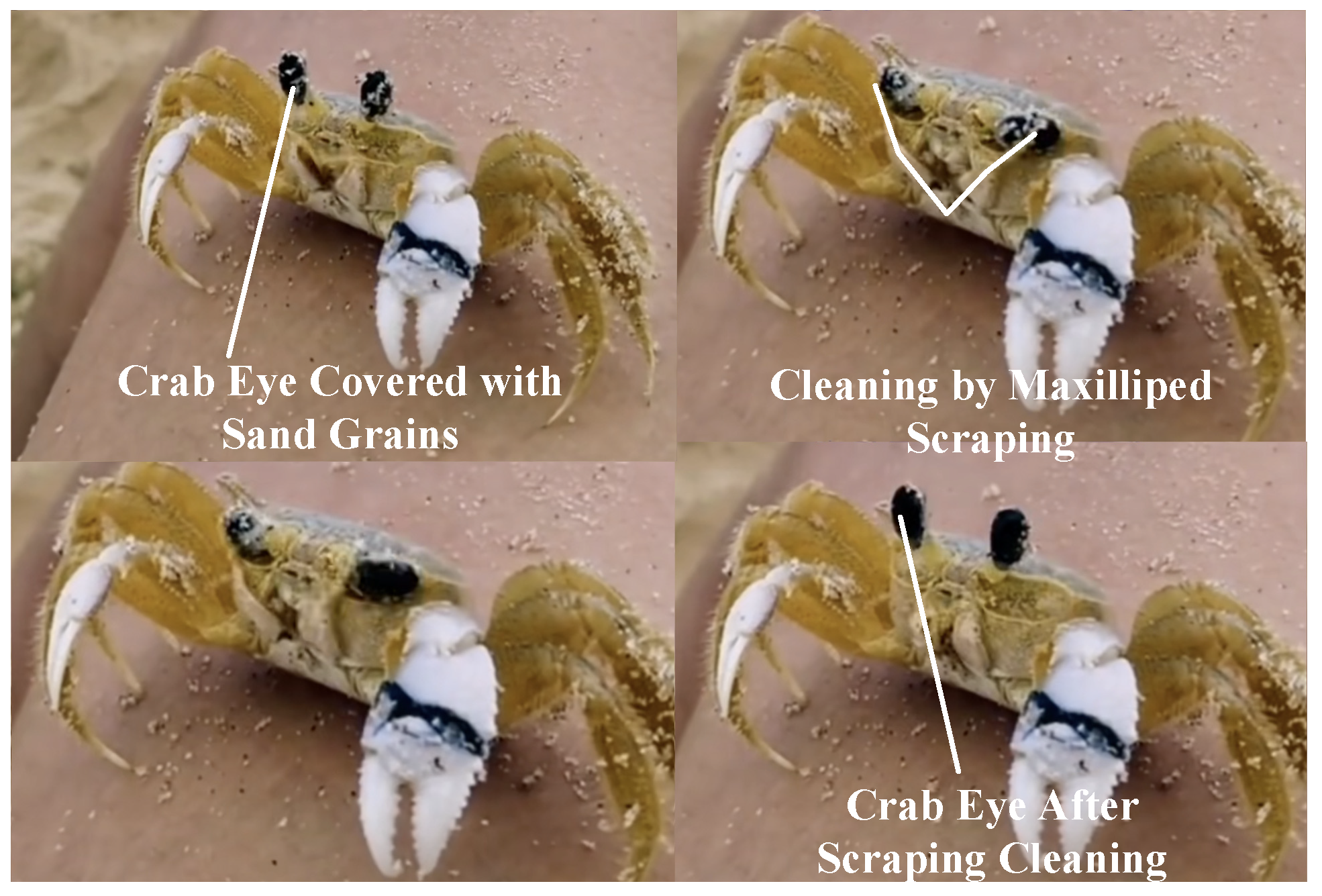
The proposed design is inspired by the natural self-cleaning behavior of crabs. In marine environments, crab eyes are frequently contaminated by sand particles and salt crystals precipitated from seawater. Crabs effectively remove these contaminants by periodically scraping their eyes with their maxillipeds, thereby maintaining visual function. This biological self-cleaning behavior is illustrated in
Figure 8.
In this biological process, the scraping action is not a separate or externally driven motion, but is inherently generated by the relative sliding and pressing between the maxillipeds and the eye surface during normal limb movement. The repeated contact, accompanied by a controlled normal force and tangential displacement, enables effective mechanical removal of adhered contaminants.
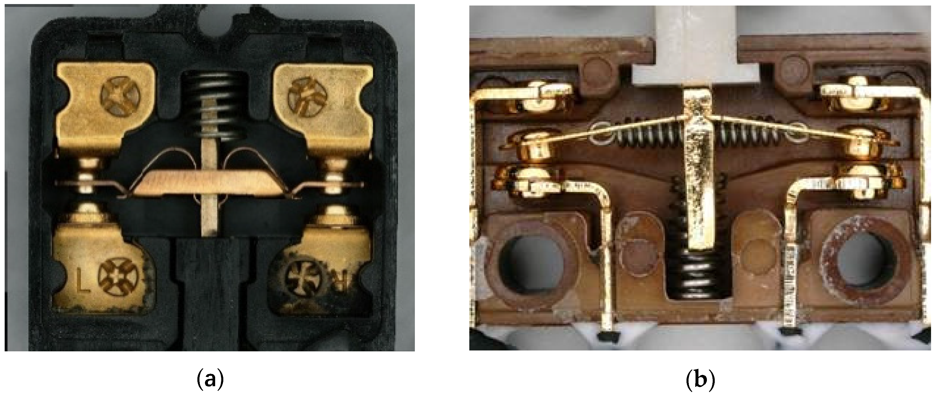
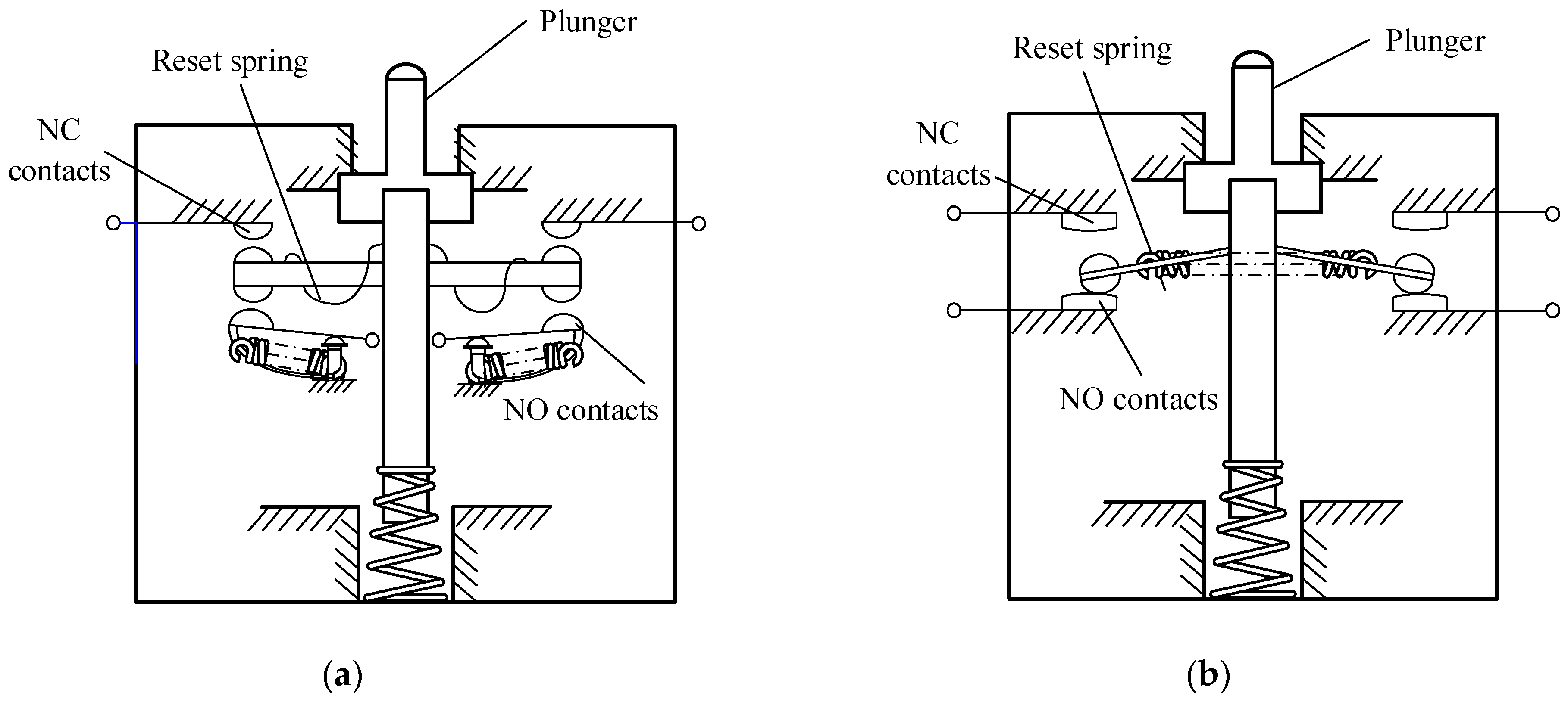
Drawing inspiration from this repetitive scraping motion, two rubbing–pressing self-cleaning limit switch configurations are proposed, as shown in
Figure 9a,b.
Figure 9a illustrates a design in which the stationary electrical contact performs the scraping action, whereas
Figure 9b presents a configuration in which the moving electrical contact performs the scraping action.
In the proposed limit switch designs, the scraping action is realized through the intrinsic kinematic coupling between the elastic deformation of the reed and the contact engagement process. During switch actuation, vertical deflection of the reed generates a coupled tangential displacement at the contact interface, resulting in a controlled rubbing–scraping motion under contact pressure. This motion produces a repeatable mechanical shearing effect on the contact surfaces, enabling the disruption and displacement of contaminants and heterogeneous films without relying on electrical arcing or external actuators.
In both designs, autonomous self-cleaning is realized through this mechanically induced rubbing–pressing motion at the electrical contact interface, effectively suppressing contaminant accumulation and insulating film formation.
4.2. Design Criteria and Performance Indicators
In limit switch operation, reliable engagement of the electrical contacts is essential for ensuring stable electrical performance and long-term reliability. Among the influencing factors, scraping displacement and contact pressing force are the two most critical design parameters.
Scraping displacement determines the effectiveness of mechanical removal of surface contaminants and constitutes the fundamental mechanism of self-cleaning. Contact pressing force ensures sufficient normal load at the electrical contact interface to penetrate surface films, reduce contact resistance, and maintain stable electrical conduction. Accordingly, scraping displacement and contact pressing force jointly define the core performance indicators for evaluating rubbing–pressing self-cleaning limit switch designs. Based on these criteria, a systematic structural optimization and performance evaluation were conducted.
4.3. Structural Optimization of the Self-Cleaning Limit Switch
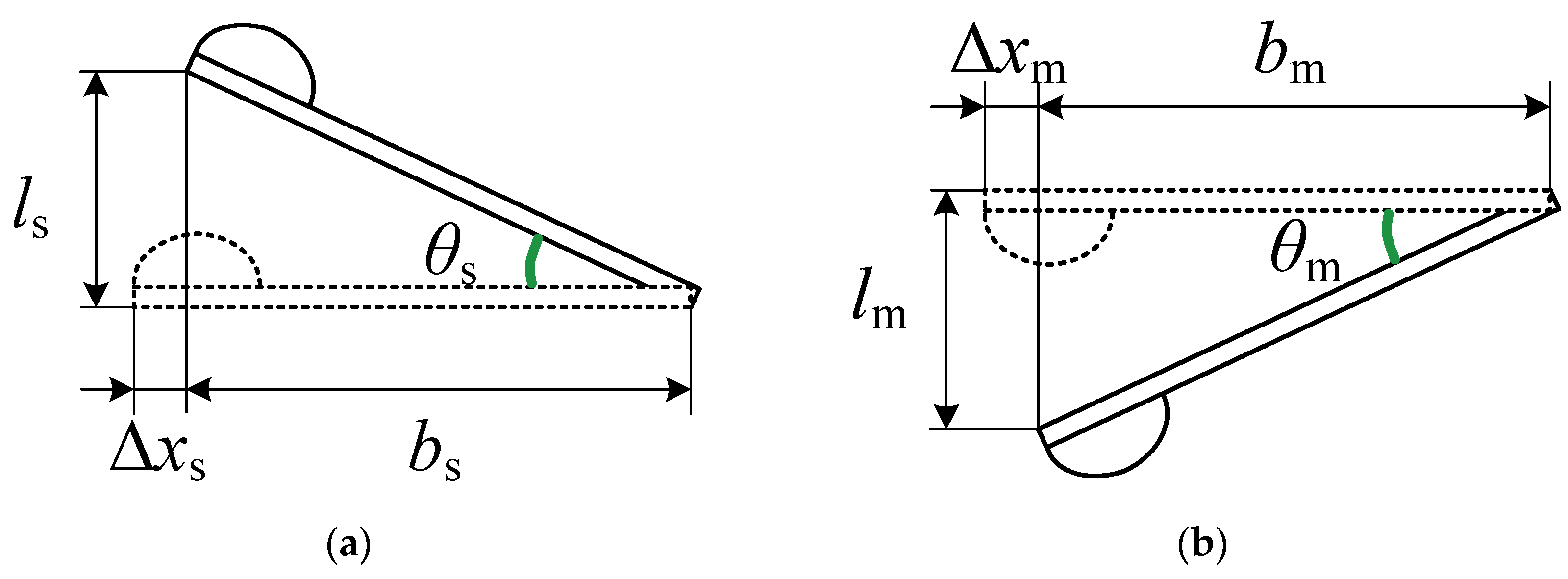
The two rubbing–pressing configurations were simplified into equivalent mechanical models, as shown in
Figure 10.
As shown in the simplified models, both configurations share an identical kinematic form. The scraping displacement
can therefore be expressed as:
where
denotes the effective length of the reed (the distance from the fixed end to the force application point),
represents the vertical deflection of the reed, and
is the motion angle of the reed.
These equations highlight the nonlinear coupling between the motion angle , vertical deflection and the reed length , governing the scraping displacement .
The influence of these parameters on the scraping displacement and motion angle has been systematically investigated:
- 1.
Reed length influence: The relationship between the effective reed length and the scraping displacement shows that increasing leads to an increase in , assuming that the motion angle remains constant. This implies that longer reeds require larger vertical deflections to maintain a constant motion angle, which, in turn, results in an increase in scraping efficiency.
- 2.
Vertical deflection influence: When the reed length is fixed, increasing the vertical deflection leads to larger motion angles and greater scraping displacement . This indicates that vertical deflection plays a significant role in determining the kinematic output of the system and is critical for efficient cleaning action.
- 3.
Reed length and vertical deflection trade-off: For a fixed vertical deflection , reducing the reed length significantly amplifies the scraping displacement , highlighting the superior scraping efficiency of shorter reeds.
The optimization of reed length and vertical deflection must be carefully balanced to maximize scraping efficiency without compromising the structural integrity or operational durability of the limit switch. By manipulating these parameters, the self-cleaning mechanism can be fine-tuned to suppress heterogeneous film accumulation, thus improving the performance and longevity of the contact surfaces under micro-current operating conditions.
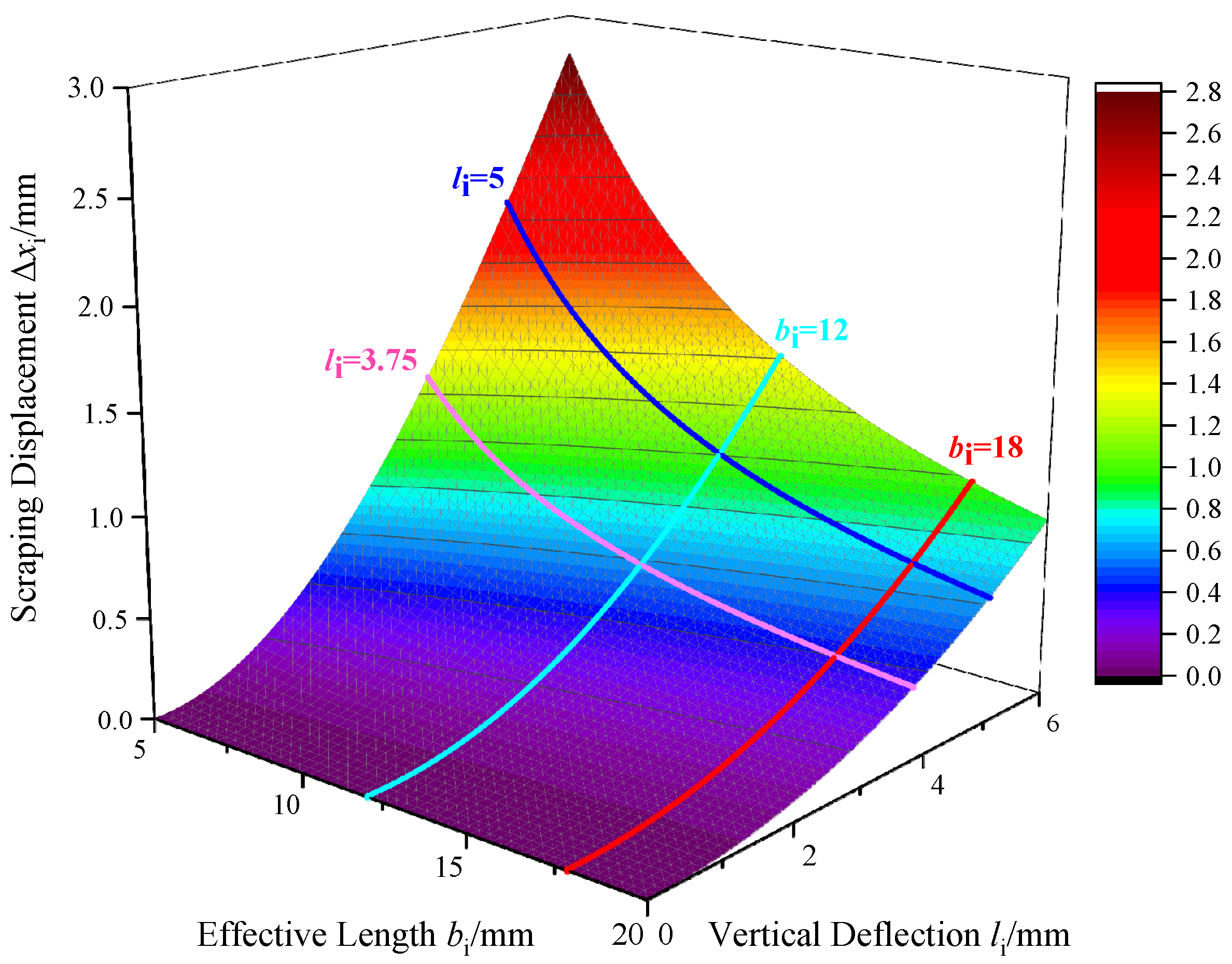
The three-dimensional surface shown in
Figure 11 illustrates the coupled relationship among scraping displacement
, effective reed length
, and vertical deflection
, providing a global visualization for multi-parameter design optimization.
4.4. Design Window Identification and Parameter Selection
In practical limit switch design, excessive motion angle may result in excessive contact pressing force, accelerated wear, or permanent reed deformation, whereas an overly small yields insufficient scraping displacement and reduced self-cleaning efficiency. Therefore, an optimal design region must balance scraping effectiveness and structural reliability.
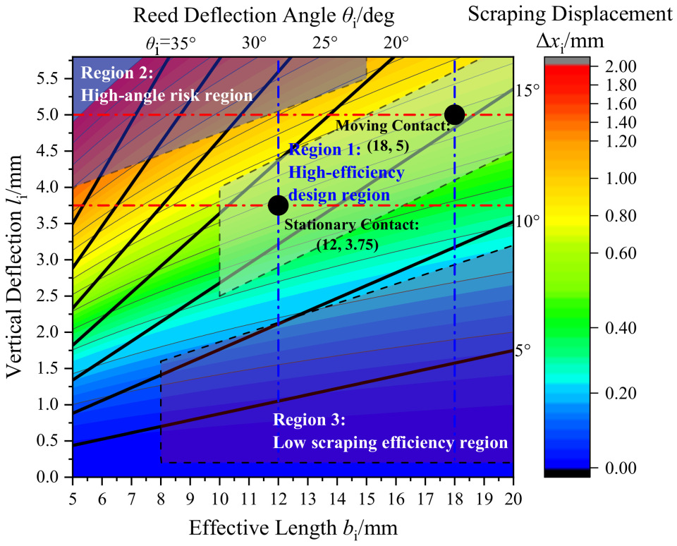
Based on the parameter space in
Figure 11, a performance efficiency contour map was constructed using dual criteria of scraping displacement
and motion angle
, as shown in
Figure 12. The design space is divided into three characteristic regions:
(1) High-efficiency design region; (2) High-angle risk region; (3) Low scraping efficiency region.
Based on this design map and spatial constraints, this study formulates a mathematical optimization problem to select the optimal parameters for both configurations. The constraints and their origins are detailed below:
- (1)
Constraint 1:
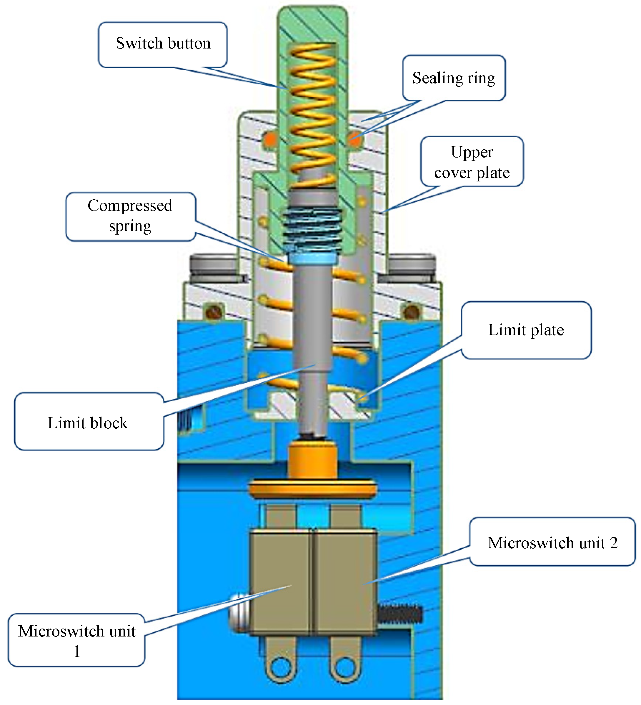
The vertical deflection of the moving contact is constrained by the pressing stroke of conventional contact-type limit switches. In practical applications, an excessively large stroke increases operating force, accelerates wear of elastic elements and contacts, and may impair reliable reset, whereas an overly small stroke leads to insufficient contact engagement and unstable conduction. Therefore, the rated pressing stroke of the contact-type limit switch (
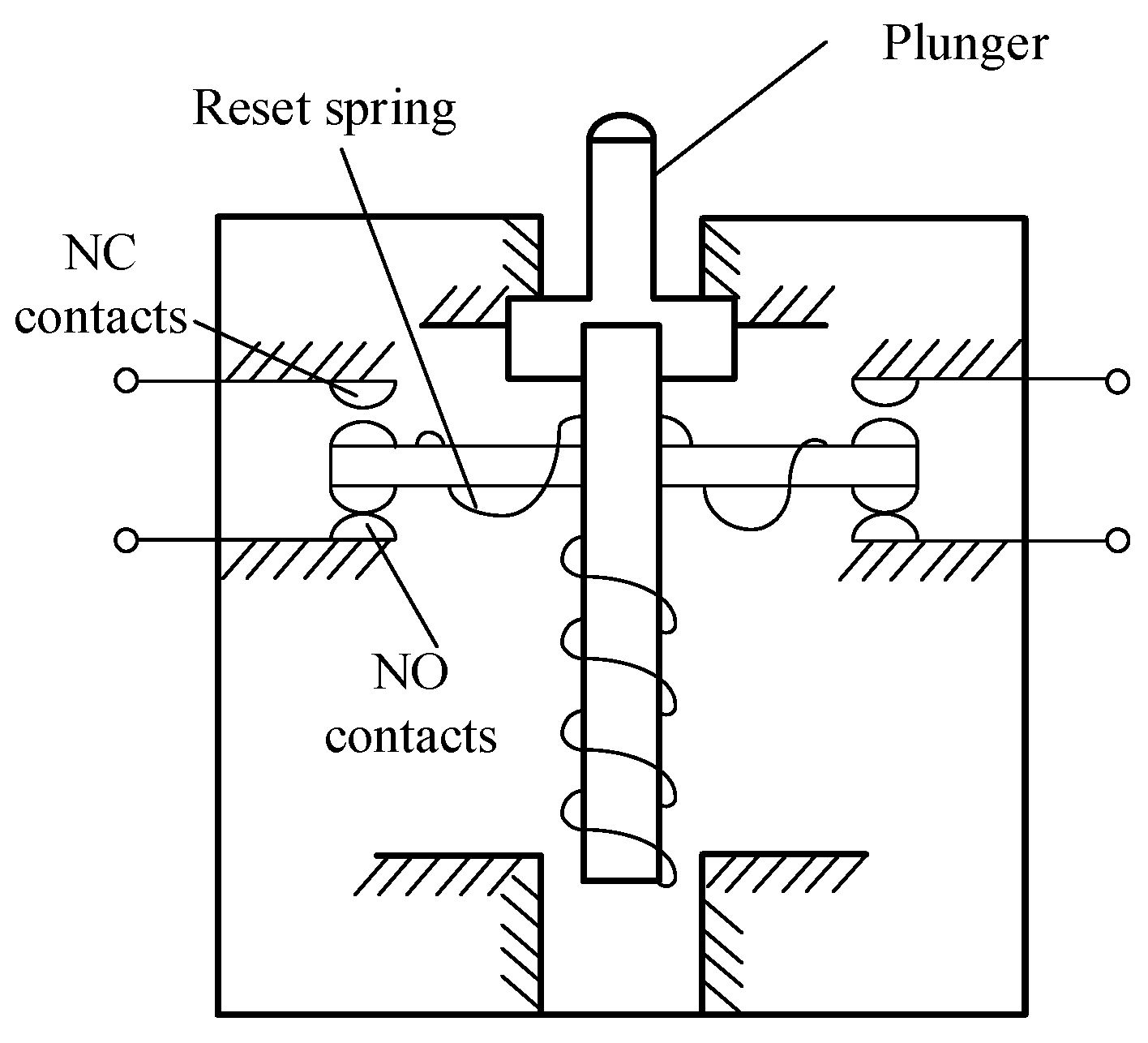
Figure 1) originally used in the system is typically designed as 5 mm, which represents a well-established engineering upper limit balancing reliability, service life, and structural safety. Therefore,
lm = 5 mm is adopted as a design constraint and reference for the moving-contact scraping configuration.
- (2)
Constraint 2:
The effective reed length of the moving contact is limited by the minimum feasible layout of the moving-contact scraping design. To ensure the full pressing stroke, stable contact engagement, and avoidance of mechanical interference,
bm must not be smaller than a certain value. Based on structural layout and assembly space analysis of the configuration shown in
Figure 9b, the minimum allowable effective reed length is determined to be 18 mm.
- (3)
Constraint 3:
For the stationary-contact scraping design (
Figure 9a), the arrangement of the central plunger imposes stricter spatial limitations. To avoid mechanical interference during the scraping motion and to ensure proper engagement between stationary and moving contacts, the effective reed length of the stationary contact must be limited. Layout analysis shows that
bs should not exceed 12 mm, which is therefore imposed as an upper bound.
- (4)
Constraint 4:
The ratio between the vertical deflection
and the effective reed length
directly governs the motion angle
, as described by Equation (2). The parametric analysis in
Figure 12 indicates that excessively large motion angles may result in excessive contact pressure, accelerated wear, or permanent reed deformation, whereas overly small motion angles lead to insufficient scraping displacement and reduced self-cleaning efficiency. To ensure effective scraping while avoiding excessive contact stress, the two configurations are designed to operate at similar and moderate motion angles, corresponding to an approximate ratio of
.
Under the structural reliability requirement (
), design points located in region 1 of the design map (
Figure 12) are preferred, as they provide high scraping displacement while avoiding excessive contact stress.
For the moving-contact scraping design (
Figure 9b), sufficient internal space allows the vertical deflection to be set at the maximum allowable value
(Constraint 1). Under Constraints 2 and 4, the effective reed length is minimized to enhance scraping displacement while maintaining structural feasibility, yielding
. This parameter set satisfies
and lies within the high-efficiency region.
For the stationary contact scraping design (
Figure 9), the effective reed length is limited to
by spatial constraints (Constraint 3). To maintain a comparable motion angle and avoid the high-angle risk region, the vertical deflection is reduced in accordance with Constraint 4, resulting in
(Constraint 4). The resulting design point also falls within the high-efficiency region and satisfies the structural reliability requirement.
4.5. Performance Comparison and Final Design Selection
Based on the optimized parameters, the ratio of scraping displacement between the stationary-contact (
) and moving-contact scraping (
) designs is given by:
The results indicate that the moving-contact scraping design achieves a slightly larger scraping displacement.
The contact pressing force
can be expressed as:
where
is the elastic modulus of the reed material,
is the reed width,
is the reed thickness, and
is the effective reed length.
Due to layout constraints, the reed thickness of the stationary-contact design () is smaller than that of the moving-contact design (), with .
Accordingly, the ratio of pressing force between the two designs is obtained as:
This result indicates that the moving-contact scraping design also provides a slightly higher contact pressing force.
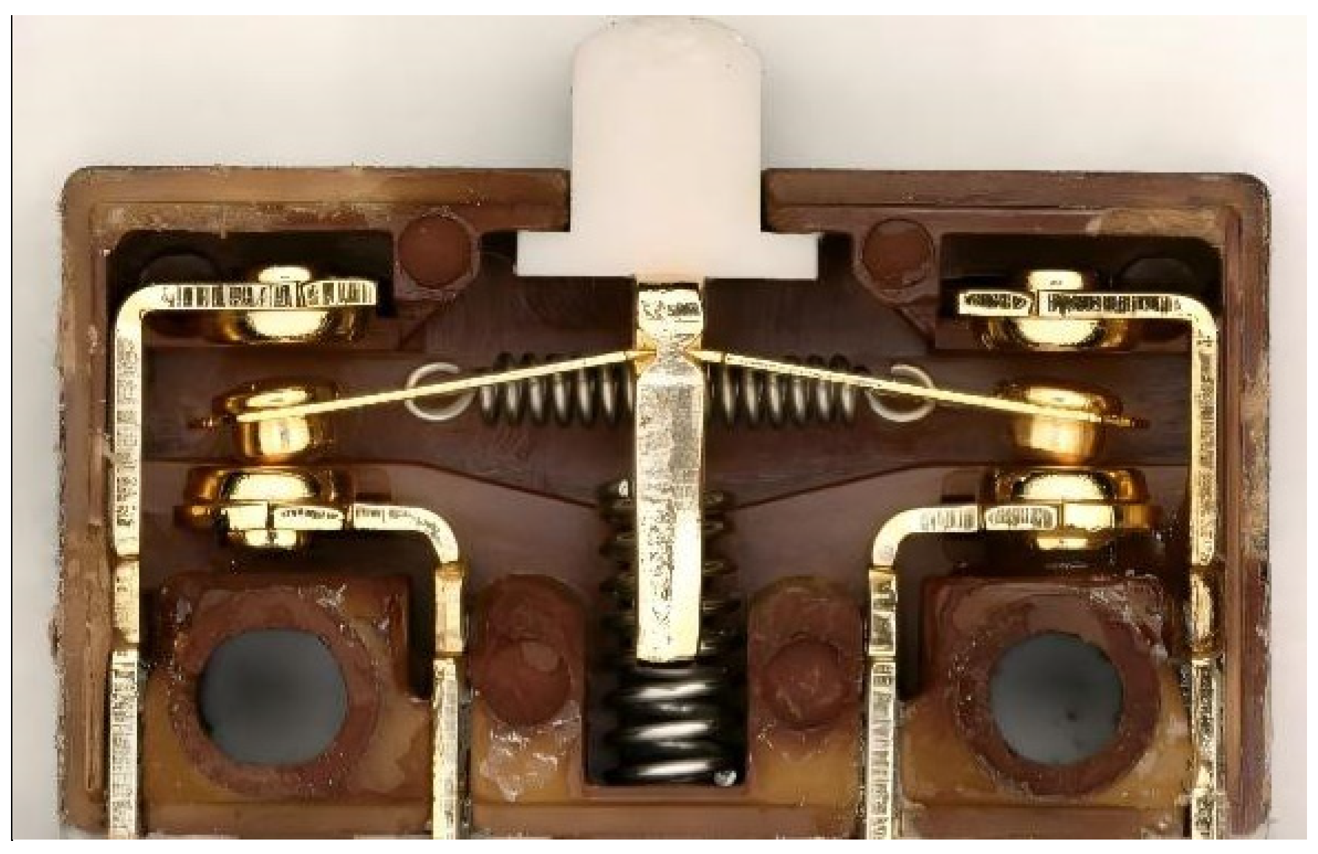
Considering both scraping displacement and contact pressing force, the moving-contact scraping rubbing–pressing self-cleaning structure was selected for implementation. A single-unit prototype microswitch is shown in
Figure 13. To ensure reliable operation under harsh marine conditions, two of these units were connected in a dual-station parallel configuration, as illustrated in
Figure 14.
5. Performance Comparison Experiments
To evaluate the operational reliability and engineering feasibility of the proposed rubbing–pressing self-cleaning limit switch under simulated marine hot–humid and salt spray conditions, a series of comparative experiments were conducted. These tests are designed to reproduce key service stresses and assess whether the new design effectively mitigates the heterogeneous film–dominated failures identified in earlier sections. First, salt spray and damp heat storage tests were applied to replicate typical marine environmental conditions, ensuring a consistent basis for comparison between conventional and self-cleaning switches. Contact resistance measurements were then performed throughout the exposure period to directly monitor conduction reliability under micro-current loads. Switching voltage waveforms were recorded to evaluate the stability of contact engagement and detect any abnormal triggering events. Finally, microstructural analysis of the contact surfaces using SEM and EDS provided detailed insight into wear, contaminant accumulation, and the effectiveness of the self-cleaning mechanism. Together, these experiments establish a complete engineering validation loop, linking environmental stress, electrical performance, and contact surface behavior to demonstrate the practical advantages of the proposed self-cleaning design.
5.1. Environmental Conditioning and Sample Preparation
Salt spray tests and damp heat storage tests were employed to simulate the marine hot–humid salt spray operating environment. The detailed test conditions are as follows:
- (1)
Salt spray test:
Temperature: 35 ± 3 °C.
pH value: 6.5–7.2.
NaCl solution concentration: 5%.
Continuous spraying for 48 h, followed by drying for 48 h.
- (2)
85/85 damp heat storage test:
Temperature: 85 ± 2 °C.
Relative humidity: 85% ± 3% RH.
Test duration: 60 days.
After completion of the environmental conditioning, the internal structures of both the snap-action contact limit switches and the rubbing–pressing self-cleaning limit switches were examined, as shown in
Figure 15.
It should be noted that the rubbing–pressing self-cleaning structure is implemented without altering the original stroke or triggering logic of the limit switch. The additional scraping displacement is generated solely through internal relative motion at the electrical contact interface, without increasing the external actuation force. This ensures good mechanical compatibility with existing systems.
5.2. Contact Resistance Measurement
Under normal conditions, the contact resistance of the normally open (NO) electrical contact of a qualified limit switch should be less than 100 mΩ. To evaluate operational reliability under harsh environments, samples were removed every 15 days during the damp heat storage test. Repeated actuation cycles (
Table 1) were performed to simulate practical operating conditions.
Subsequently, to verify whether the switch still met the specification under its typical operating current, its contact resistance was measured. Given that the micro-current limit switches in this study have an operating current range of 50 mA to 100 mA, we employed the four-wire (Kelvin) method and selected 0.1 A as the measurement current to accurately assess its contact state under rated micro-current conditions. This current value is well below the threshold that would induce significant alteration of the contact surface, thereby ensuring the measurement process itself did not interfere with the contact characteristics. The measurement was performed using a programmable DC power supply (with a compliance voltage of 24 V).
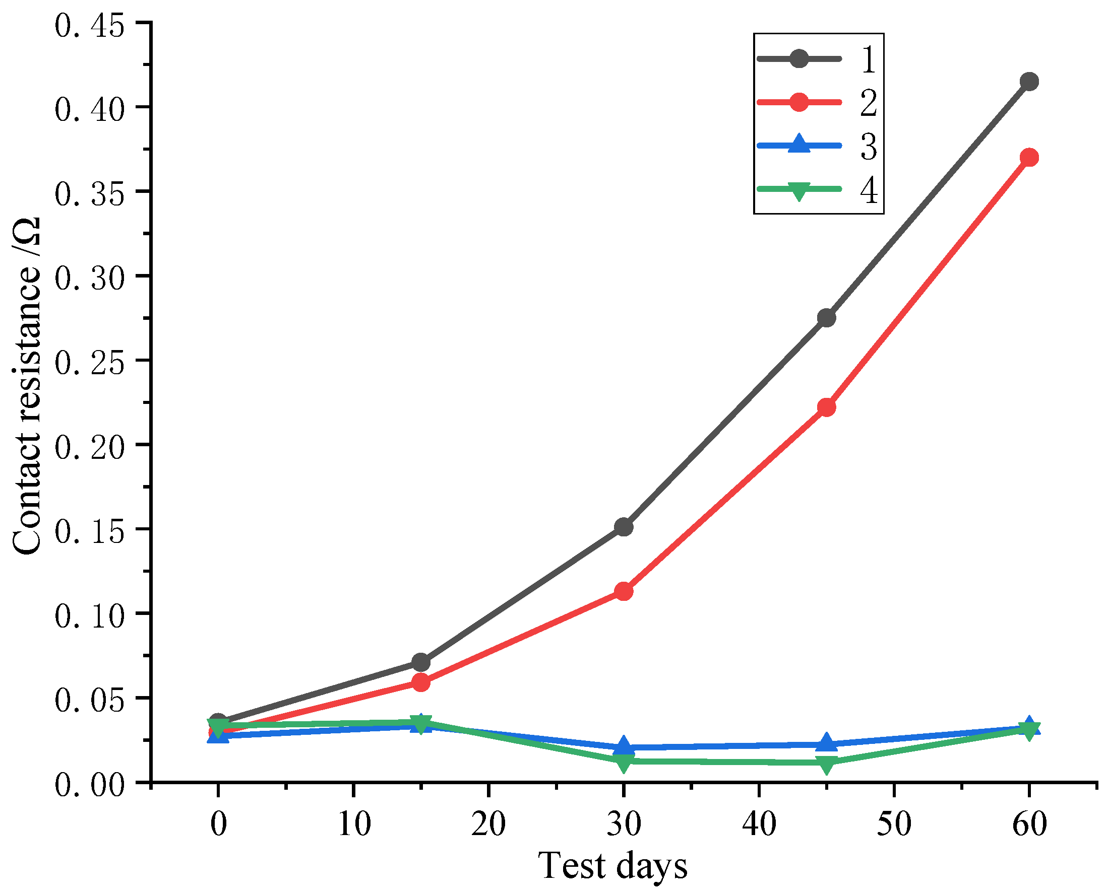
The measurement results are shown in
Figure 16, where samples No. 1 and No. 2 correspond to conventional snap-action limit switches, and samples No. 3 and No. 4 correspond to rubbing–pressing self-cleaning limit switches.
The snap-action limit switches exhibit pronounced instability in contact resistance, with varying degrees of abnormal increase as the test duration progresses. In particular, between days 15 and 30, continuous accumulation of heterogeneous films causes the contact resistance to exceed the standard threshold of 100 mΩ. Continued operation under such conditions may lead to unstable signal transmission, localized contact heating, or complete functional failure.
In contrast, although the rubbing–pressing self-cleaning limit switches show an initial decrease followed by a slight increase in contact resistance, the overall fluctuation remains minimal. The maximum measured resistance is only 0.035 Ω, well below the 0.1 Ω limit. These results indicate that the proposed self-cleaning design effectively maintains stable electrical contact performance even after prolonged exposure to salt spray and damp heat environments.
5.3. Voltage Waveform Measurement
The switching voltage waveform directly reflects electrical contact engagement behavior and contact stability, providing an important basis for failure characterization.
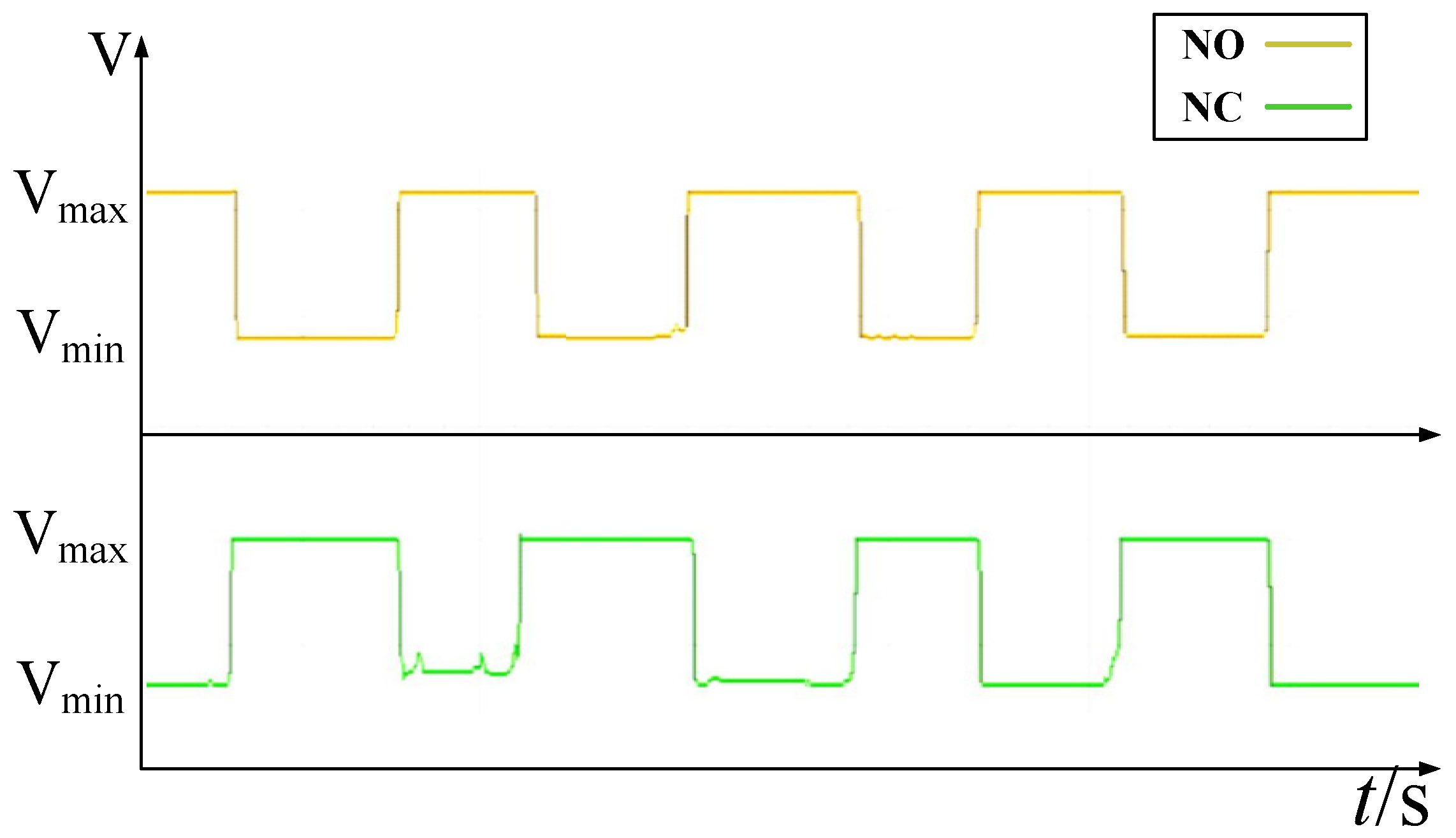
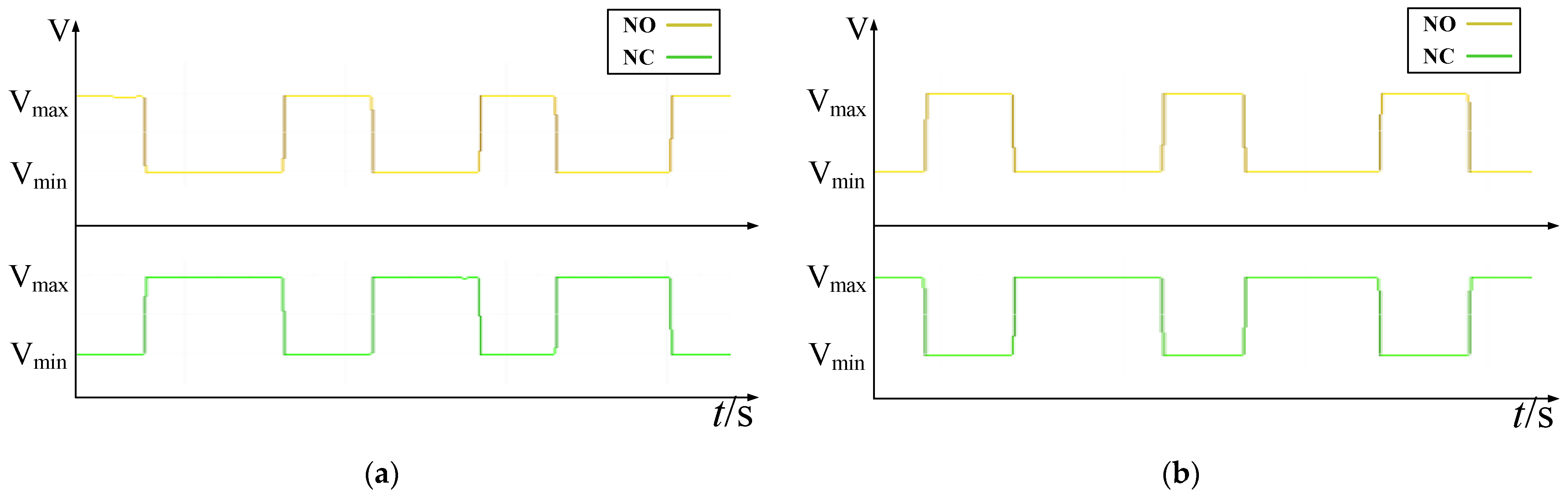
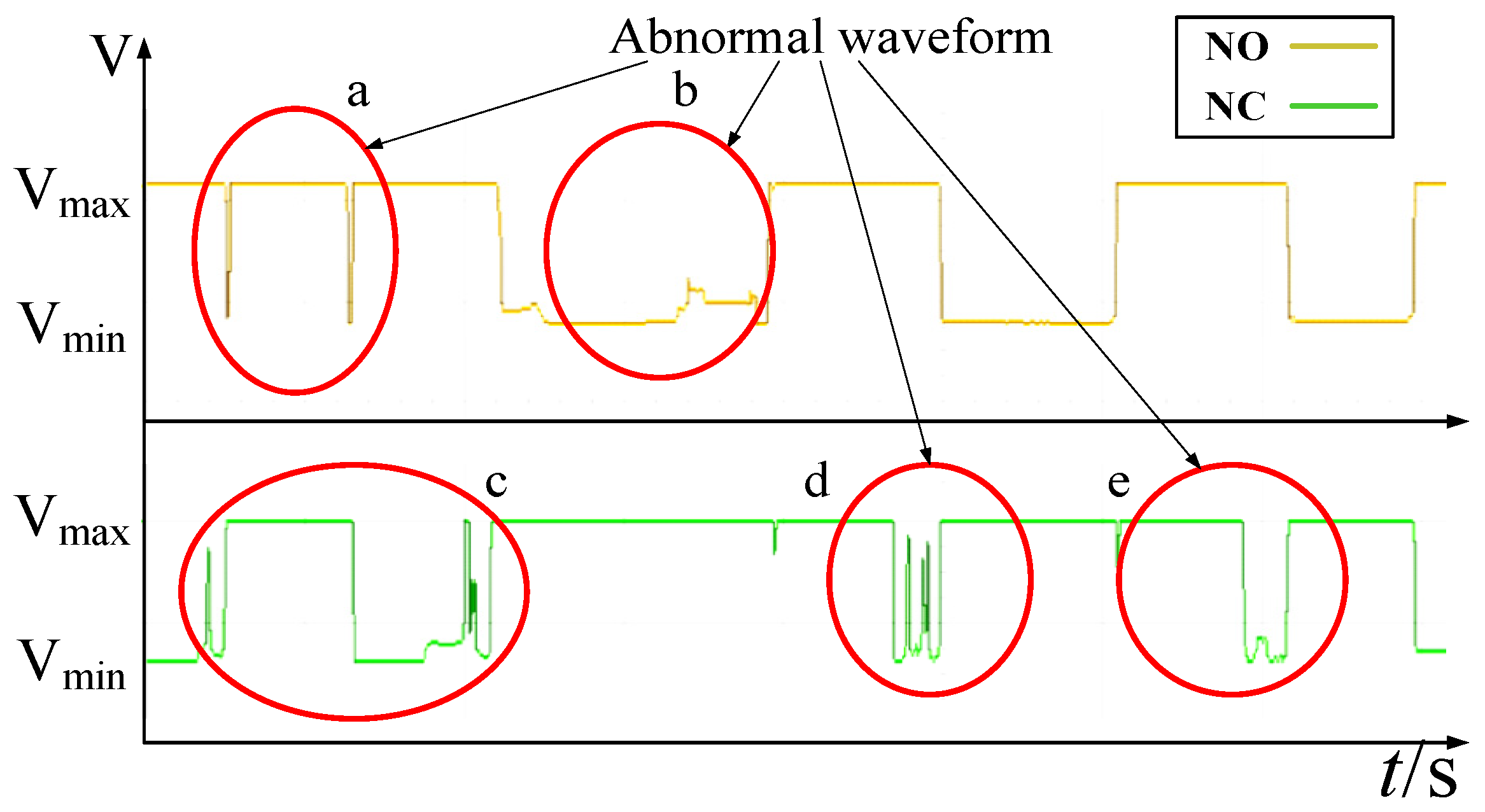
After salt spray exposure and 60 days of damp heat storage, the limit switches were repeatedly actuated. An oscilloscope was used to monitor the voltage waveforms of each microswitch unit during contact closing and opening. Abnormal waveforms were recorded for analysis. The voltage waveforms of snap-action limit switches and rubbing–pressing self-cleaning limit switches are shown in
Figure 17 and
Figure 18, respectively.
Analysis of
Figure 17 reveals multiple waveform abnormalities in the snap-action limit switches:
- (1)
At position a, the NO contact is mechanically closed, but the voltage does not drop as expected, indicating ineffective electrical conduction.
- (2)
At position b, the NO contact voltage fluctuates during closure, reflecting unstable contact resistance.
- (3)
At position c, an abnormal voltage rise is observed during closure of the normally closed (NC) contact.
- (4)
At positions d and e, the NC contact voltage fails to decrease normally upon closure.
These phenomena indicate unstable conduction behavior at both NO and NC electrical contact interfaces in the snap-action limit switches.
In contrast, the voltage waveform of the rubbing–pressing self-cleaning limit switch shown in
Figure 18 remains stable throughout the switching process, with no abnormal fluctuations observed. This confirms stable contact engagement behavior and reliable electrical performance.
5.4. Contact Morphology and Elemental Composition Analysis
To evaluate the effectiveness of the rubbing–pressing self-cleaning mechanism in removing heterogeneous films during operation, scanning electron microscopy (SEM) and energy-dispersive spectroscopy (EDS) were employed to analyze the morphology and elemental composition of the electrical contact surfaces.
5.4.1. Snap-Action Contact Limit Switch
Both the moving and stationary electrical contacts of the snap-action limit switches are fabricated from Ag–SnO2–ZnO alloy and are gold-plated to enhance conductivity and oxidation resistance.
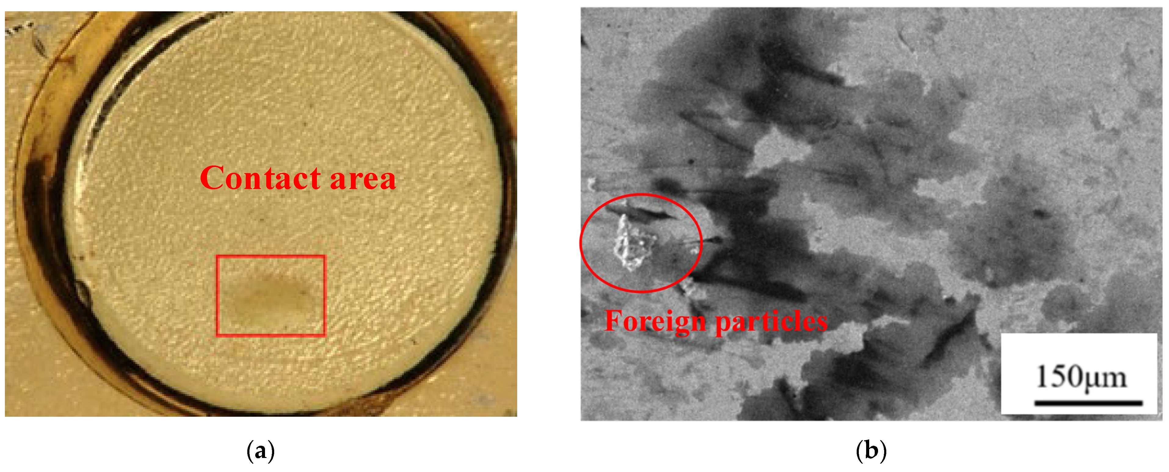
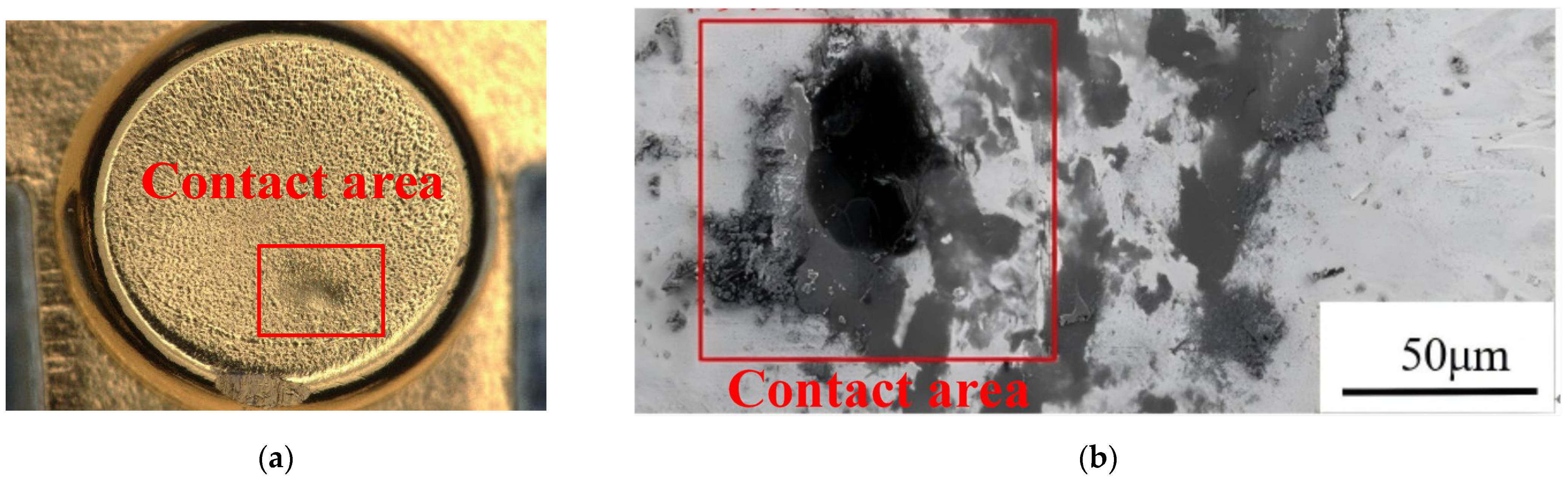
After salt spray exposure and 60 days of damp heat storage, SEM images of the stationary contact surface (
Figure 19) reveal impact-induced depressions resulting from snap-action motion. These depressions provide favorable sites for contaminant accumulation. Pronounced wear features and debris accumulation are observed along the edges of the contact region.
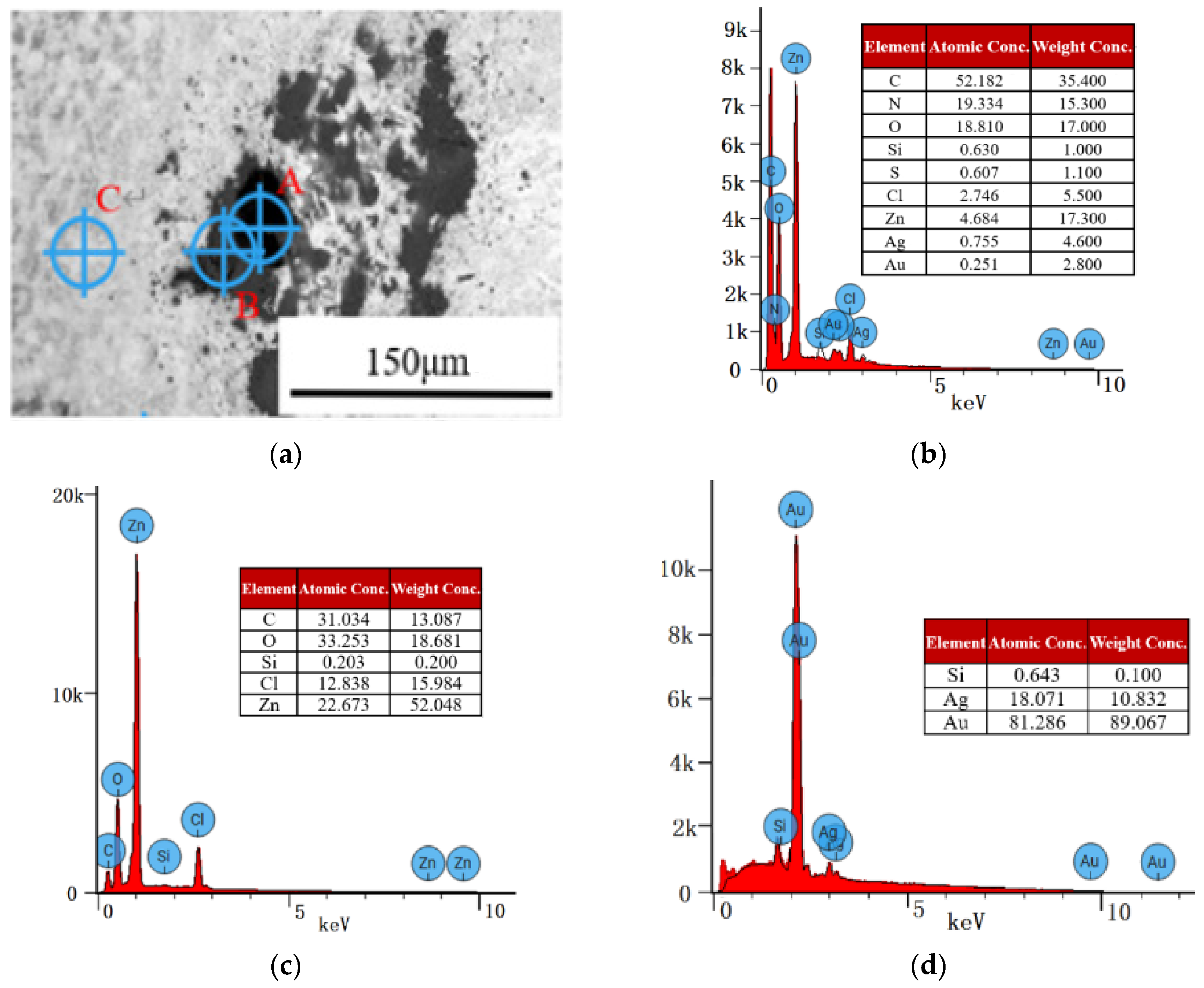
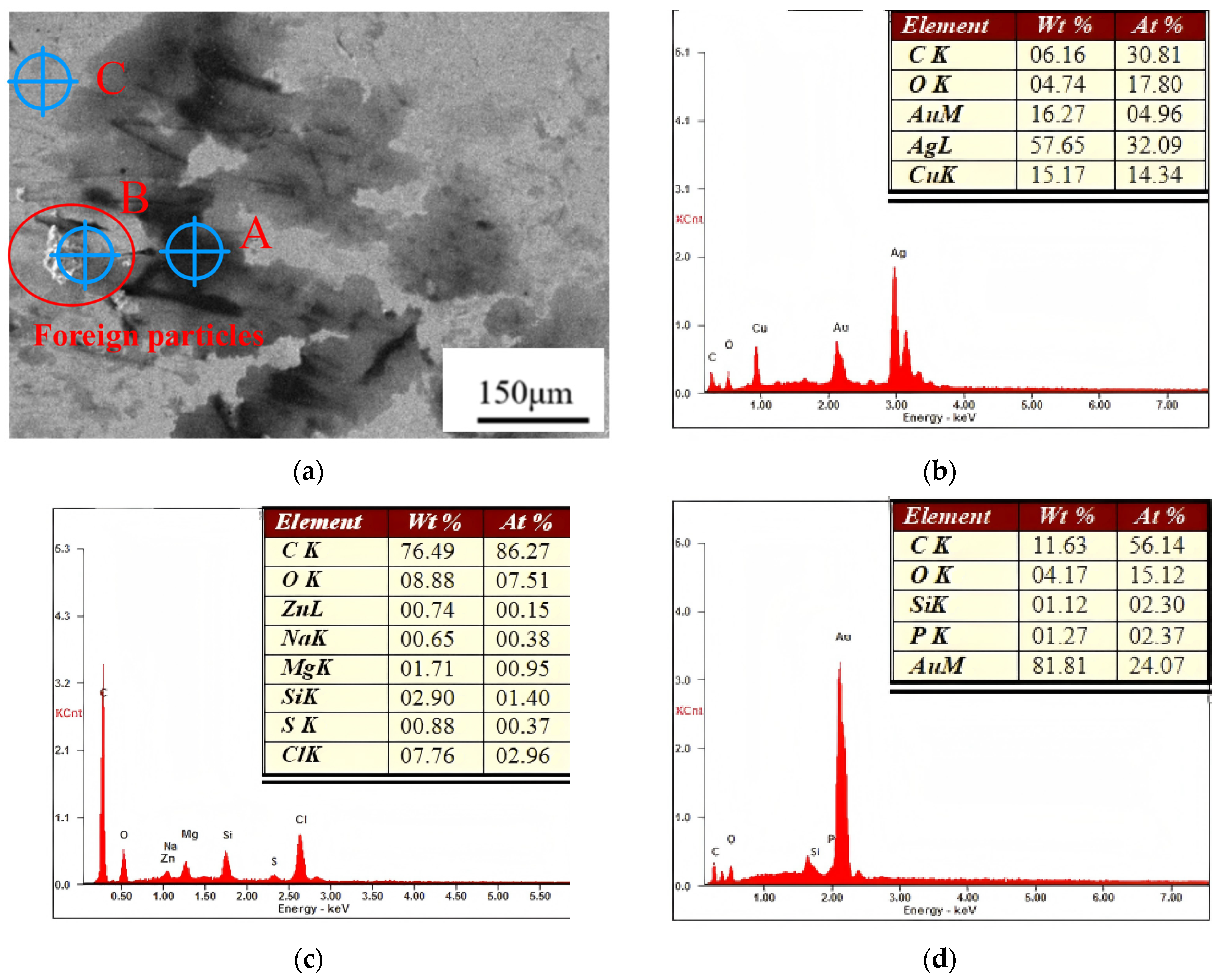
EDS analysis was performed on three characteristic regions (A, B, and C) indicated in
Figure 20a, with results shown in
Figure 20b–d.
Region A corresponds to the severely worn contact area, characterized by dominant elements C, N, O, Cl, and Zn, with extremely low Ag and Au content. This indicates that the gold plating has been largely removed and that a high-resistance heterogeneous film—primarily composed of zinc chlorides and carbon–nitrogen–oxygen compounds—has formed on the silver-based substrate, leading to a sharp reduction in electrical conductivity.
Region B corresponds to the debris accumulation region and exhibits a similar elemental composition (C, O, Cl, Zn), indicating that the debris originates from mechanical delamination of the heterogeneous film.
Region C corresponds to the non-contact region, which remains smooth and is dominated by Au and Ag, indicating preservation of the original gold plating.
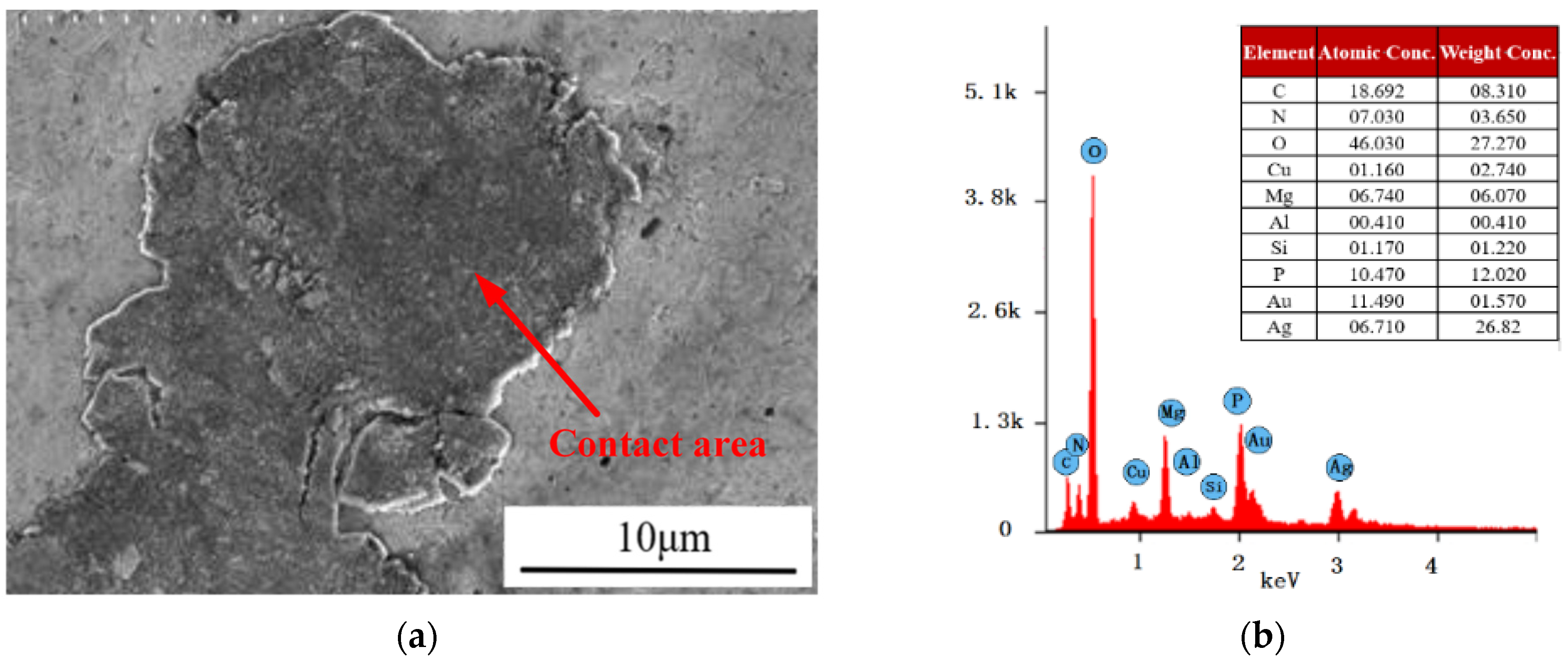
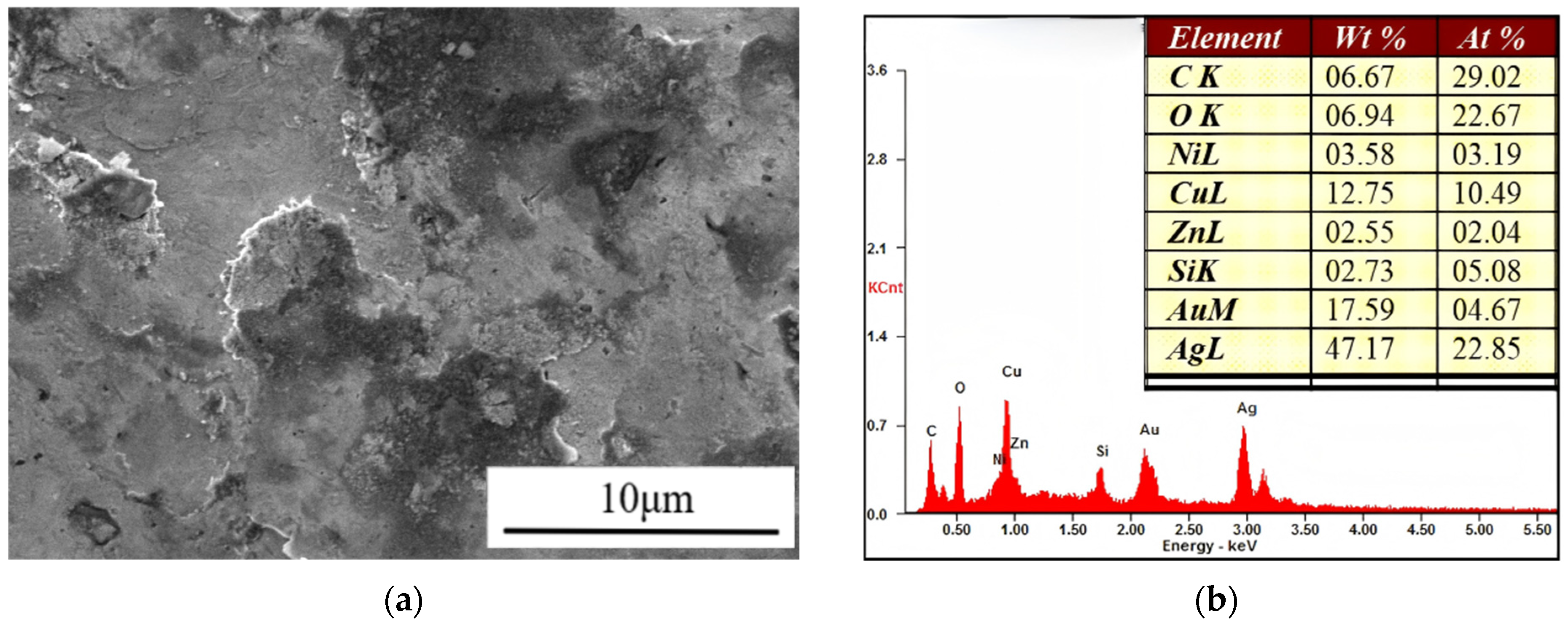
SEM images of the moving contact surface (
Figure 21) reveal a distinct heterogeneous deposition layer in the contact region. EDS analysis shows dominant elements C, N, O, Mg, P, Au, and Ag. Based on the elemental composition, this deposition layer is identified as a metal-containing complex oxide film, which is a major contributor to increased contact resistance.
Overall, the contact regions of the snap-action limit switches are heavily covered by high-resistance heterogeneous films, whereas non-contact regions remain morphologically intact. The formation of these films prevents reliable electrical conduction in the closed state.
Further analysis indicates that impurity elements enriched in the contact regions (C, O, Cu, Zn, K, Cl, P, and N) are consistent with those detected within the microswitch housing, suggesting that contaminants originate from internal particle migration driven by mechanical vibration, surface roughening, frictional heating, and electrostatic adsorption.
5.4.2. Rubbing–Pressing Self-Cleaning Limit Switch
The electrical contacts of the rubbing–pressing self-cleaning limit switches are also fabricated from Ag–SnO2–ZnO alloy with gold-plated surfaces. Importantly, the self-cleaning mechanism does not rely on preservation of the gold layer but instead operates by mechanically disrupting chloride- and phosphate-dominated heterogeneous films. Consequently, stable electrical contact can still be maintained by the Ag-based alloy even after partial depletion of the gold layer.
SEM images of the contact surfaces after environmental testing are shown in
Figure 22. Compared with snap-action contacts, the rubbing–pressing contacts exhibit a wider contact region with a clearly defined scraping path. Pronounced friction marks are observed within the contact region, while contaminants are mainly distributed at the edges of the scraping path. No deposition layers are observed within the primary contact region, confirming effective self-cleaning behavior.
EDS analysis was conducted on three regions marked in
Figure 23a.
Region A corresponds to the severely worn contact region and is dominated by C, O, Au, Ag, and Cu, with no detectable Zn, N, or Cl. This indicates substantial removal of the gold plating and exposure of the silver-based substrate. Despite increased mechanical wear, the reduced C and O contents indicate effective disruption of high-resistance heterogeneous films.
Region B corresponds to the debris accumulation region and is dominated by C, O, Si, and Zn, with significantly reduced Cl content, indicating outward transport of contaminants by the rubbing–pressing motion.
Region C corresponds to the non-contact region and remains smooth and Au-dominated, indicating intact gold plating.
SEM and EDS analysis of the moving contact surface (
Figure 24) reveal no obvious heterogeneous deposition layer. Clear scraping marks are observed, and no phosphorus-containing compounds are detected, confirming effective removal of phosphate-based oxide films.
Although more pronounced mechanical wear is observed, the rubbing–pressing self-cleaning mechanism effectively suppresses film-dominated contact failure, thereby maintaining stable electrical performance under micro-current conditions.
5.5. Summary of Comparative Performance
Compared with conventional snap-action limit switches, the proposed rubbing–pressing self-cleaning microswitch effectively disrupts and removes high-resistance heterogeneous films dominated by chloride- and phosphate-containing compounds, maintaining stable electrical performance under micro-current marine conditions. SEM observations indicate increased mechanical wear due to the rubbing action; however, under the low-frequency operating conditions of this study (less than 500 actuations per month), such wear has a limited impact on service life. In contrast, conventional snap-action switches fail within 30–60 days under the same conditions, whereas the self-cleaning design maintains reliable operation, achieving a balanced trade-off between mechanical durability and electrical reliability.
6. Conclusions
This study investigates the triggering failure of shipborne limit switches operating under micro-current loads in marine hot–humid salt spray environments, systematically elucidates the underlying failure mechanisms, and proposes a rubbing self-cleaning dual-redundant limit switch design. The main conclusions can be summarized as follows:
- (1)
Through combined electrical performance measurements, accelerated environmental exposure tests, and detailed analyses of electrical contact surface morphology and elemental composition, it is demonstrated that corrosion products and externally introduced contaminants within the microswitch unit migrate under mechanical vibration and repeated switching cycles. These contaminants preferentially accumulate at the electrical contact interfaces, forming high-resistance heterogeneous films primarily composed of carbon-, oxygen-, chlorine-, and phosphorus-containing compounds and metal oxides. The formation of such heterogeneous films is identified as the fundamental cause of unstable conduction and triggering failure of shipborne limit switches under micro-current load conditions.
- (2)
The electrical contact behavior of limit switches is strongly dependent on the applied current magnitude. Under micro-current conditions, insufficient arc energy is generated during contact closure, preventing effective breakdown or removal of the high-resistance heterogeneous films and ultimately leading to contact failure. As the current increases, arc discharge occurs during contact engagement. When the current reaches 2A or higher, the high-energy arc effectively removes the heterogeneous films from the contact surfaces, enabling recovery of normal electrical contact performance.
- (3)
Based on the identified failure mechanism, and inspired by the biomimetic cleaning behavior of crab maxillipeds scraping contaminants from the eyes, a novel rubbing self-cleaning dual-redundant limit switch structure is proposed. By introducing controlled rubbing and scraping motions between the moving and stationary electrical contacts during engagement, the formation of high-resistance heterogeneous films is suppressed at the source and contaminants are directionally displaced toward non-contact regions, enabling autonomous contact surface cleaning under micro-current operating conditions.
- (4)
Comparative salt spray and 85 °C/85% RH damp heat storage tests indicate that, compared with conventional snap-action switches, the proposed self-cleaning design exhibits lower and more stable contact resistance, more consistent switching voltage waveforms, and superior long-term operational reliability, suggesting a potential extension of service life under micro-current loads.
In summary, this work establishes a coherent framework linking failure mechanisms, electrical contact behavior, biomimetic structural design, and environmental validation. The results provide both mechanistic insights and a practical engineering solution for improving the reliability of shipborne micro-current limit switches in harsh marine environments. Furthermore, the proposed rubbing self-cleaning concept offers a transferable biomimetic design paradigm for high-reliability electrical contact devices operating under low-current conditions.
To address the observed limitations, future work will aim to further evaluate the improvements of reliability with larger sample sets to statistically confirm potential service-life extension, and to mitigate the increased mechanical wear in the rubbing self-cleaning mechanism through the use of wear-resistant ceramics or novel synthetic materials, thereby further extending operational lifespan.