1. Introduction
The utilization of high-torque-density motors has emerged as a significant technological trend in the contemporary robotics industry. Across diverse application domains, including humanoid robots, walking robots, rehabilitation robots, and wearable robots, high-torque-density motors offer several critical advantages. Primarily, high-torque-density motors substantially enhance back-drivability by enabling the reduction in gear ratio or, in certain instances, the complete elimination of reduction gears. This characteristic is particularly essential in collaborative robots and rehabilitation robots that require physical human–robot interaction. Enhanced back-drivability facilitates intuitive, natural, and safe interactions with external environments or humans by enabling compliant joint responses in unexpected collisions, while high-torque-density motors further contribute to superior control precision and overall system reliability [
1,
2]. The reduction in gearing stages diminishes nonlinear elements such as backlash, friction, and hysteresis, thereby enabling more accurate position and force control. Additionally, the decreased nonlinearity from reduction gears improves the accuracy of torque estimation through motor current. This can offer a significant advantage in that precise torque control is achievable without additional torque sensors, suggesting the potential for reducing overall system costs and simplifying the mechanical structure.
The implementation of high-torque-density motors can effectively reduce the volume and weight of robotic systems, thereby decreasing the overall system inertia and improving energy efficiency. In humanoid and wearable robots, this weight reduction directly translates to extended battery life and enhanced user comfort. Moreover, by reducing the overall manufacturing costs of robots, high-torque-density motors present potential solutions to various challenges currently faced by robotic technology [
2,
3,
4,
5,
6,
7].
However, conventional high-torque-density motors inherently generate high back-electromotive force (back-EMF) due to their structural characteristics, which inevitably leads to limited speed performance. Despite this limitation, many robotic applications demand not only high torque density but also high-speed operation. For instance, humanoid robots during walking motions and industrial collaborative robots performing rapid movements require both high torque and high speed. A traditional approach to overcoming this limitation involves increasing the supply voltage for motor operation. A higher voltage allows a greater usable voltage per phase, which can handle the increased back-EMF and thus enable higher speed operation. However, this voltage-boosting strategy entails several drawbacks, including increased system complexity, safety concerns, and higher costs. In particular, robotic systems involving direct human interaction—such as wearable or rehabilitation robots—are subject to strict safety regulations. According to international safety standards (e.g., IEC 60335), the operating voltage of systems in contact with the human body is generally limited to below 50 V in order to mitigate potential hazards during physical interaction [
8]. Consequently, such robot systems typically employ battery configurations with a maximum of 48 V [
9,
10]. This voltage constraint poses a direct limitation on enhancing the speed performance of high-torque-density motors. Therefore, improving the speed characteristics of these motors under the 50 V safety limit, without altering the mechanical configuration, remains a significant challenge. Due to these limitations, there are currently applications in the robotics field where the use of high-torque-density motors—despite their importance—is not feasible. Therefore, this study proposes two innovative winding techniques aimed at enhancing the speed performance of high-torque-density motors while maintaining their torque characteristics under a limited supply voltage of below 50 V and analyzes the synergistic effects arising from their combination.
The first technique is the PCW (Parallel Connected Winding) configuration approach. This method reconfigures the conventional SCW (Series-Connected Winding) configuration into a parallel topology, effectively reducing the equivalent phase resistance and inductance. The reduction in these parameters minimizes voltage drop, thereby increasing the usable voltage per phase. Furthermore, the parallel configuration lowers the back-electromotive force (back-EMF) to approximately half at the same rotational speed, which enables the motor to achieve a higher maximum speed under the same voltage conditions. Theoretically, this enables the motor to deliver up to twice the output power compared to a conventional SCW while preserving the inherent torque characteristics of a high-torque-density motor.
The second technique involves the application of the OEW (Open-End Winding) configuration. Conventional BLDC motors typically adopt a SCW, in which the neutral point is shared and the motor operates under a two-phase conduction mode, resulting in only half of the supply voltage being applied to each phase. In contrast, the OEW eliminates the neutral point and enables independent control of each phase, allowing the full supply voltage to be directly applied to every phase. This configuration modification significantly improves voltage utilization and, under the same voltage conditions, can theoretically achieve up to a two-fold enhancement in speed performance compared to the SCW [
11].
The primary contribution of this study is the proposal of a novel POEW (parallel open-end winding) configuration, which integrates the previously described PCW and OEW techniques to enhance the speed performance of high-torque-density motors under 50V-limited robotic systems. By combining the two-fold speed improvement of the PCW method and the two-fold improvement of the OEW, the POEW approach theoretically achieves up to a four-fold increase in maximum rotational speed. POEW is expected to effectively overcome the speed limitations of high-torque-density motors in voltage-constrained environments, thereby meeting the various operational demands of robotic applications. Moreover, since the POEW requires no changes to the physical configuration of the stator or rotor, but only a modification in the winding method, it can be implemented with minimal structural alteration. Therefore, the proposed POEW-based motor is particularly advantageous in applications where both torque and speed performance are critical, such as wearable robots and collaborative robots. The proposed motor is visualized in
Figure 1, and its dynamic characteristics are summarized in
Table 1. Notably, the transition from a SCW to a PCW configuration results in only an 8 g increase in total motor mass, demonstrating the practicality of the proposed configuration modification.
2. Designing of Motor and Drive System
2.1. Designing of Motor
2.1.1. Governing Equations of Motor
The three-phase BLDC motor exhibits identical forms of governing equations regardless of the winding connection topology. Therefore, the dynamic characteristics of various connection methods can be systematically compared and analyzed. In this study, the governing equations describing motor behavior are defined as follows: Equation (1) represents the voltage equation of the motor. Equation (2) defines the stator resistance based on the winding method. Equation (3) expresses the stator inductance based on the winding method. Equation (4) denotes the magnitude of the back-electromotive force (back-EMF). Equation (5) defines the back-EMF constant according to the number of series turns per phase. Equation (6) presents the three-phase back-EMF waveform equations [
12,
13,
14].
In Equation (1), represents the voltage of each phase (n = a, b, c), is the phase resistance, is the phase current, and is the back-EMF. In Equation (2), denotes the resistivity of the conductor, is the total length of the coil, is the effective number of series turns per phase, is the cross-sectional area of the coil, and is the number of parallel paths. In Equation (3), is the phase inductance, is the magnetic permeability, is the cross-sectional area of the magnetic path, and is the magnetic path length. In Equation (4), represents the peak amplitude of the back-EMF, is the back-EMF constant, and is the electrical angular velocity. In Equation (5), denotes the magnetic flux. Equation (6) describes the three-phase sinusoidal back-EMF waveforms, where each phase is shifted by 120 degrees where denotes the time variable aligned to the electrical angle reference frame.
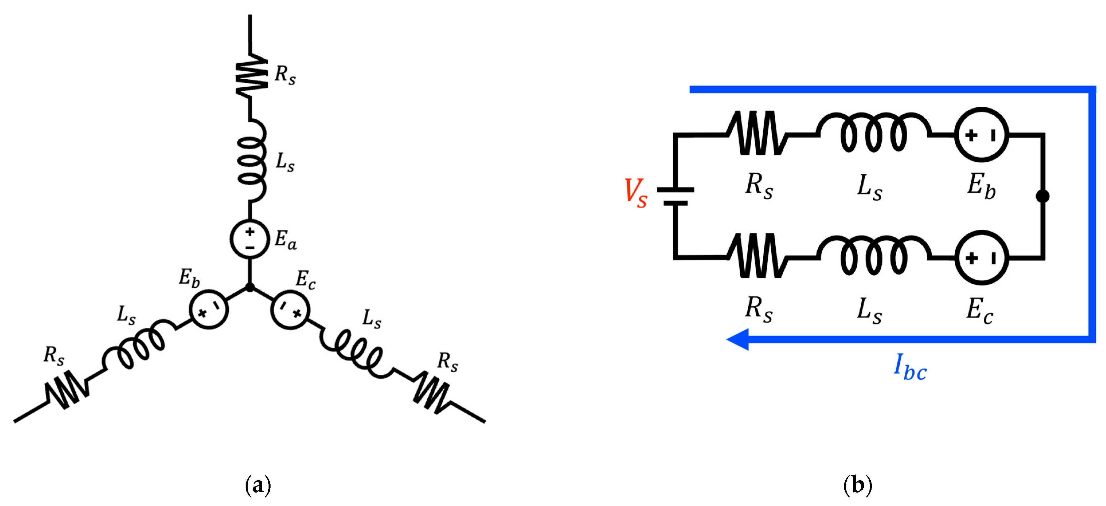
2.1.2. SCW
The SCW is illustrated in
Figure 2a, and the corresponding two-phase conduction system is illustrated in
Figure 2b. In this configuration, two phases are simultaneously energized by a single voltage source. The mathematical model of the two-phase conduction system is given as follows [
13,
14]:
In Equation (7),
denotes the usable voltage considering the voltage drop across the winding resistance and
represents the supply voltage applied to the motor. Equations (8)–(11) derive the motor’s saturation speed based on the back-EMF relationship. The motor speed reaches a saturation at the electrical angular velocity
that satisfies Equation (11). Equation (12) illustrates the influence of the number of series-connected turns on the motor’s speed limitation [
14].
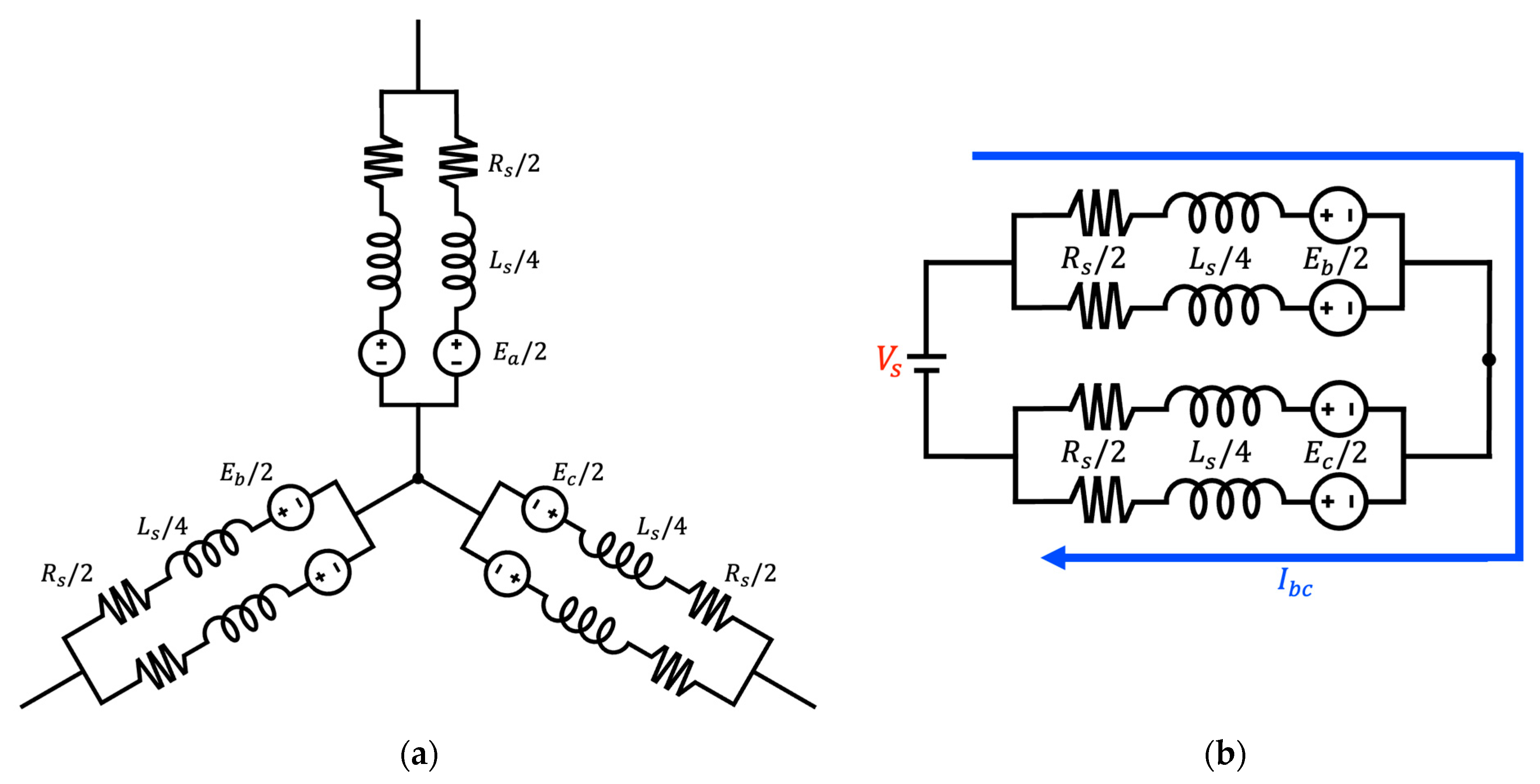
2.1.3. PCW
The schematic of the proposed PCW is illustrated in
Figure 3a, which consists of two parallel Circuits. The associated two-phase conduction system is illustrated in
Figure 3b that is identical to that used in the conventional SCW. A key feature of the proposed PCW topology is that it maintains the same total number of turns as the conventional SCW while utilizing two parallel current paths. This effectively reduces the number of series-connected turns per phase (
) by half. As described by Equation (2), a reduction in
along with a doubling of the number of parallel branches (
) leads to a substantial decrease in phase resistance (
), theoretically reducing it to one-fourth of the original value. Similarly, according to Equation (3), the phase inductance (
), which is proportional to the square of the number of turns, is reduced to approximately one-eighth when
is halved. These reductions in both resistance and inductance significantly lower the voltage drop across the windings, thereby increasing the
for motor operation. This increased
directly contributes to an improvement in the motor’s maximum saturation speed. Furthermore, as shown in Equation (12), the back-EMF constant (
), which is linearly dependent on
, also decreases by half under the PCW. Consequently, the motor’s speed saturation point is theoretically doubled compared to that of a SCW under the same voltage supply. These characteristics make the PCW particularly advantageous for robotic actuator applications that require high-speed operation within limited voltage environments.
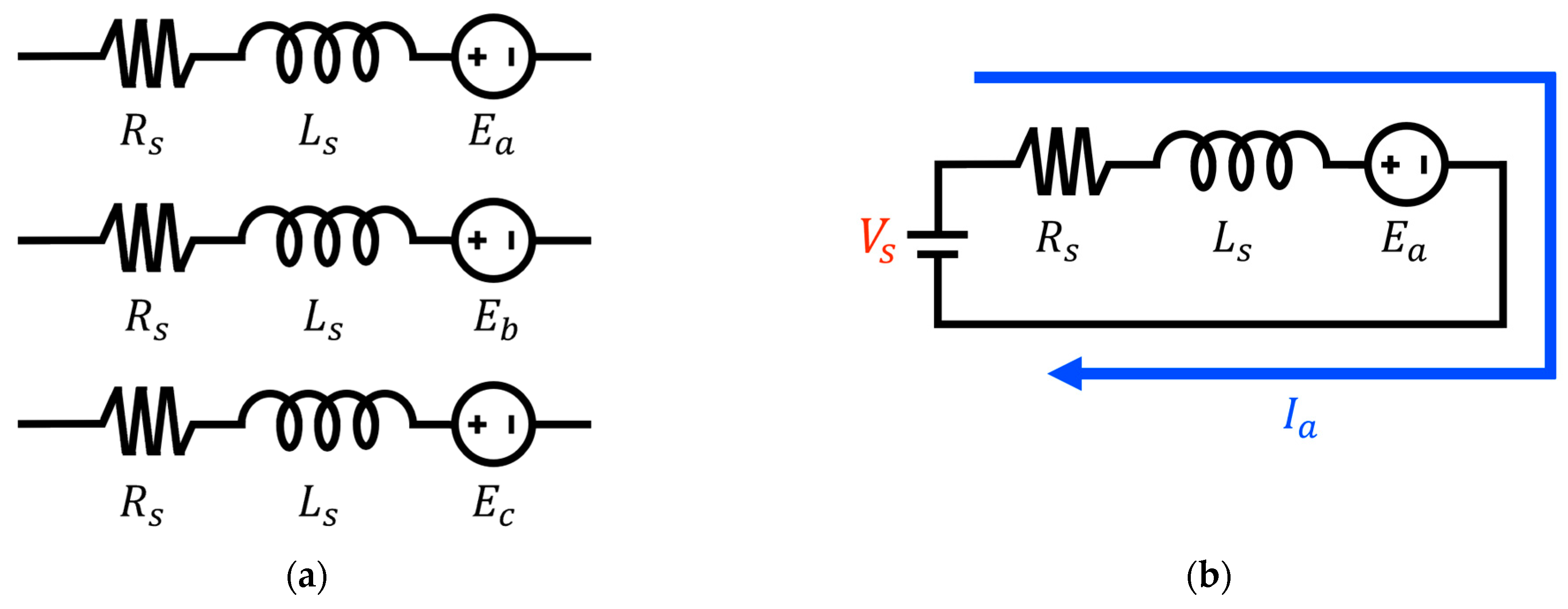
2.1.4. OEW
The circuit schematic of the OEW is shown in
Figure 4a, and the associated single-phase conduction system is depicted in
Figure 4b. Unlike the SCW, the OEW employs a conduction system in which each phase is independently driven by a dedicated voltage source. This architectural difference has a significant impact on the motor’s electrical performance. Equation (13) defines the effective phase voltage in the OEW, while Equations (14)–(17) represent the relationship between the usable voltage and the back-EMF, ultimately leading to the determination of the motor’s saturation speed [
15,
16,
17,
18,
19].
In contrast to the SCW, the OEW topology significantly reduces voltage drop, as observed by comparing Equations (7) and (13). Another key distinction lies in the mechanism governing saturation speed. As shown in Equations (14)–(17), the saturation speed in the OEW is determined solely by the back-EMF of a single phase, unlike the SCW. Consequently, under identical voltage conditions, the OEW can achieve a higher saturation speed. This performance benefit represents a significant technological advancement for robotic actuator systems operating under voltage-constrained conditions [
20].
2.1.5. POEW
The POEW proposed in this study represents an innovative winding configuration that integrates the advantages of existing approaches. As illustrated in
Figure 5a, this configuration maintains the same total number of turns per phase as OEW while utilizing two parallel circuits, effectively reducing the number of series-connected turns by half. The conduction system, shown in
Figure 5b, adopts the same single-phase conduction system used in the OEW, thereby maximizing voltage utilization. The electrical characteristics of the POEW can be understood as the result of the synergistic effect of the PCW and OEW methods. Similarly to the PCW, the phase resistance
is significantly reduced to one-fourth of its original value, as described by Equation (2). Likewise, the inductance
decreases to approximately one-eighth, according to Equation (3). The reduction in resistance and inductance further mitigates the voltage drop observed in OEW operation, as described in Equation (13), thereby increasing
, which in turn contributes directly to improved high-speed performance. From the back-EMF perspective, the halved number of series turns results in a proportional reduction in the back-EMF constant
, leading to a theoretical saturation speed that is approximately twice as high as that of the OEW and four times that of the conventional SCW under the same voltage constraints. The POEW offers a cost-effective solution to overcoming the speed limitations of high-torque-density motors in voltage-limited environments. Notably, this approach can be implemented without altering the physical configuration of the stator or rotor, requiring only a modification to the winding configuration. This feature adds practical value by enabling straightforward performance upgrades in existing robotic systems. This performance benefit represents a significant technological advancement for robotic actuator systems operating under voltage-constrained conditions.
2.2. Designing of Inverter
2.2.1. SCW and PCW Inverter
The motor drive systems for the SCW and PCW were implemented based on the six-step inverter topology, as illustrated in
Figure 6.
Table 2 presents the switching sequences corresponding to the Hall sensor signals for the six-step inverter. To minimize switching losses and improve efficiency, a unipolar PWM control strategy—in which only the lower switches are modulated—was employed, instead of the bipolar method that modulates both upper and lower switches. This unipolar approach reduces the switching frequency, thereby minimizing switching losses and mitigating electromagnetic interference (EMI). Compared to the bipolar method, the unipolar PWM technique also significantly reduces output voltage ripple, resulting in suppressed torque ripple and lower acoustic noise during motor operation. In
Table 3, the ‘Interrupt’ column indicates the logical states of the Hall sensor signals. Upward arrows represent rising edges, while downward arrows indicate falling edges [
21].
2.2.2. OEW and POEW Inverter
The motor drive systems for OEW and POEW adopt a topology consisting of three full-bridge inverters, as illustrated in
Figure 7. Unlike the previously described six-step inverter, this configuration enables independent voltage application to each phase. Each phase is driven by its own full-bridge inverter, allowing for fully bidirectional and independent phase control. This architecture is a critical enabler for maximizing phase voltage utilization—one of the key advantages of both OEW and POEW.
Table 3 presents the switching sequence for OEW/POEW inverters, which expands the conventional Hall sensor-based control logic to cover all four switches in each full-bridge inverter. This control strategy facilitates seamless implementation using the same Hall sensor infrastructure and control algorithms as in conventional systems [
20,
22].
3. Experiment Comparing the Motor Dynamics
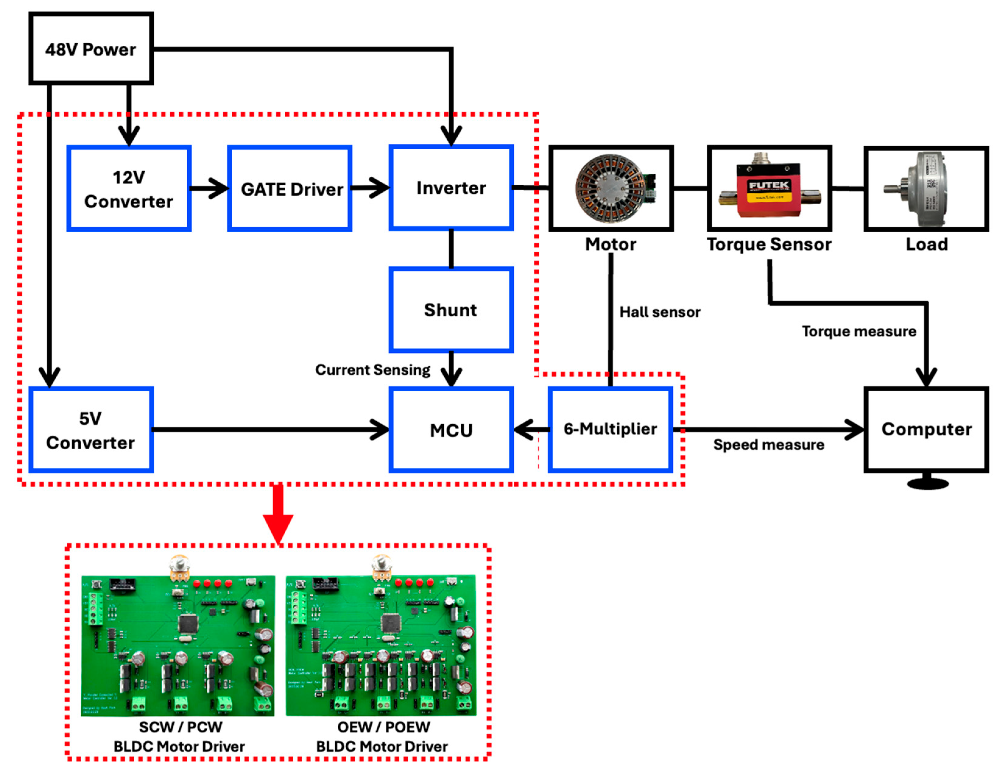
3.1. Experiment Setting
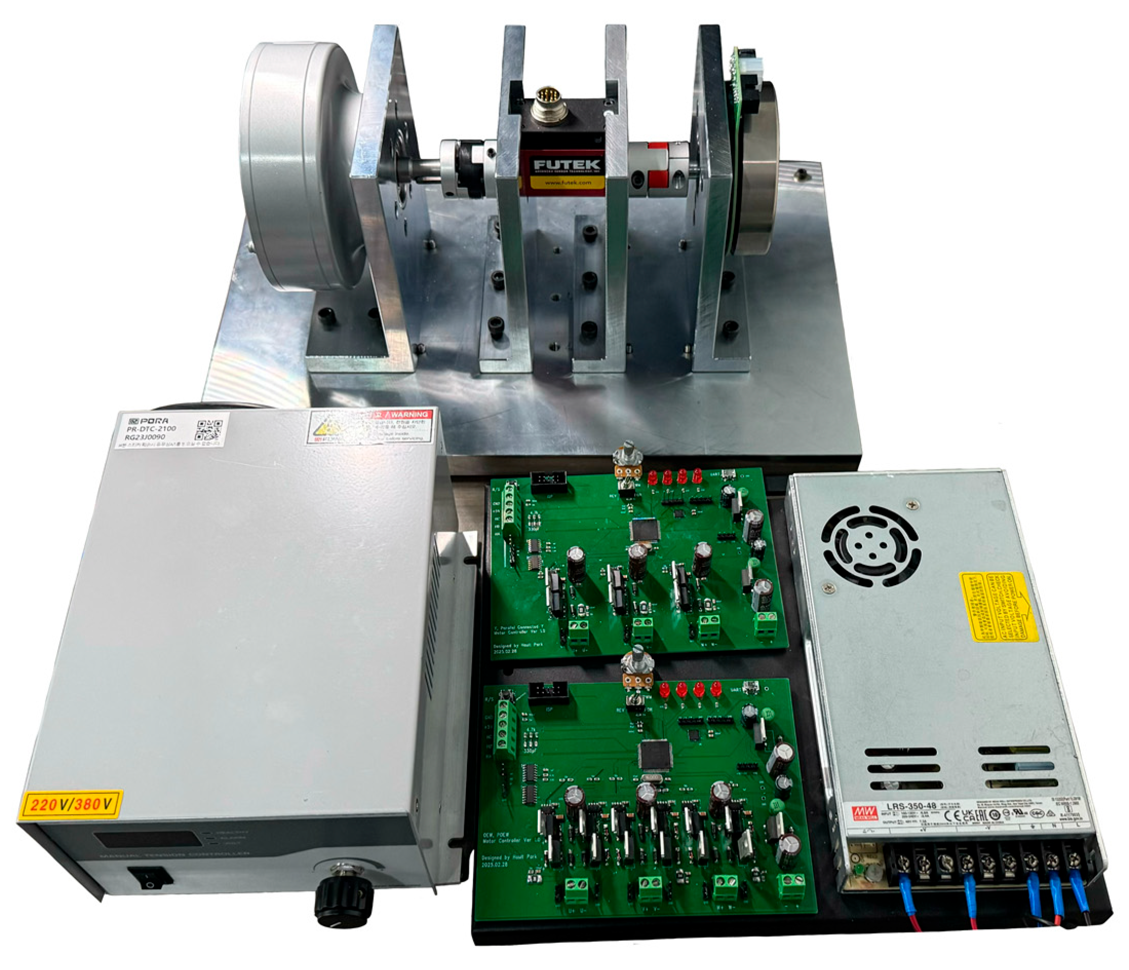
The overall configuration of the proposed experimental setup is illustrated in
Figure 8. The setup is powered by a 48 V DC power supply, with the main supply voltage directly applied to the drain terminals of the inverter. A microcontroller unit (MCU) for system control and monitoring requires a 5 V supply, while the gate driver circuit operates at 12 V. Both voltages are efficiently derived from the main 48 V source via buck converters. To evaluate the performance of the proposed winding configurations, two key experiments were conducted: (1) speed characteristic evaluation and (2) torque characteristic analysis. As shown in
Figure 9, a dynamometer system was employed to ensure precise load control and accurate performance measurement. To minimize parameter variations—such as resistance and inductance—caused by the manual winding process, the neutral points of both the single SCW and PCW motors were internally connected within the motor driver PCB. This approach effectively isolates the effects of the winding configurations from other variables, enabling the accurate assessment of the proposed winding configuration alone. The structural and electrical characteristics of each winding configurations are presented in
Table 4.
3.2. Speed Experiment of Each BLDC Motor
The rotational speed of motor was measured using Hall sensor signals. To improve resolution, the signal was amplified six-fold and processed using the M-method for accurate speed estimation. The mathematical basis of the M-method is provided in Equations (18) and (19), and the parameters used for speed calculation are detailed in
Table 5 [
23].
Here, denotes the mechanical rotation angle, (Pulses Per Revolution) represents the maximum number of pulses generated per revolution, and is the sampling time of the measurement system. The variable refers to the pulse count within the sampling window.
3.3. Torque Experiment of Each BLDC Motor
In this study, it is crucial to verify that the torque characteristics are preserved in addition to achieving improved high-speed operation. If the proposed winding configuration enhances speed performance but compromises torque output, it will not fulfill the intended function of a high-torque-density motor. To enable a systematic comparison of torque performance, the output torque of each motor was measured using a precision dynamometer while incrementally increasing the phase current from 0 A to 5 A in steps of 0.5 A. Equation (20) presents the formula for calculating the torque constant, while Equations (21) and (22) define the Joule heating power and the motor constant, respectively.
Here, denotes the measured torque and refers to the Joule heating power, which represents the copper loss due to resistive heating. is the torque constant and is the motor constant. In this study, in addition to the conventional evaluation using the torque constant , the motor constant was introduced as a supplementary performance metric. The motor constant is defined as the ratio of the generated torque to the square root of the Joule heating power and serves as a key indicator of the motor’s torque generation efficiency relative to thermal losses. A higher value of implies a more efficient motor design, capable of producing greater torque under the same thermal dissipation conditions. Since parallel winding reduces the phase resistance by a factor of four, comparing the motor constant is particularly important when evaluating torque performance relative to heat generation.
4. Results
4.1. Experimental Result of Speed Characteristics Comparison
The speed characteristic experiment was conducted under a 48 V power supply condition, and the maximum speed and speed ripple for each winding configuration were measured at a maximum inverter duty cycle of 94%. The results of this experiment are visualized in
Figure 10 and summarized in
Table 6. For the conventional SCW, the maximum speed was measured to be 1214.4 RPM with a low-speed ripple of 19 RPM. Since this value is similar to the motor specification provided by the manufacturer, the inverter design used in this experiment can be considered appropriate for the test environment. The PCW, which incorporates parallel windings, exhibited a maximum speed of 2312.7 RPM due to reduced phase resistance, mitigated voltage drop, and a lower back-EMF constant. This represents approximately a 1.9-fold improvement compared to SCW. The speed ripple was also maintained at a stable level of 19 RPM, experimentally verifying that the PCW contributes to speed improvement. The OEW, despite being a series configuration, eliminates the neutral point and allows full voltage application for each phase. This resulted in a maximum speed of 2331.2 RPM, approximately 1.92 times higher than SCW. The speed ripple was measured at 20 RPM, also showing stable operating characteristics. These findings demonstrate that OEW is an effective method to enhance speed even in SCW configurations. Finally, the POEW, which combines both PCW and OEW benefits, achieved the highest speed of 4273.8 RPM, representing a 3.52-fold improvement over SCW, 1.85-fold over PCW, and 1.83-fold over OEW. The speed ripple remained low at approximately 19 RPM, comparable to the other configurations, indicating stable rotational performance. These results confirm that the speed performance of high-torque-density motors can be significantly improved through winding configuration modifications, even under a limited 48 V supply. The consistently low ripple across all configurations further suggests high practical applicability. Particularly in applications such as humanoid and wearable robots, where both high torque and high speed are essential, the proposed POEW offers an efficient and safe actuation solution.
4.2. Experimental Results of Torque Characteristics Comparison
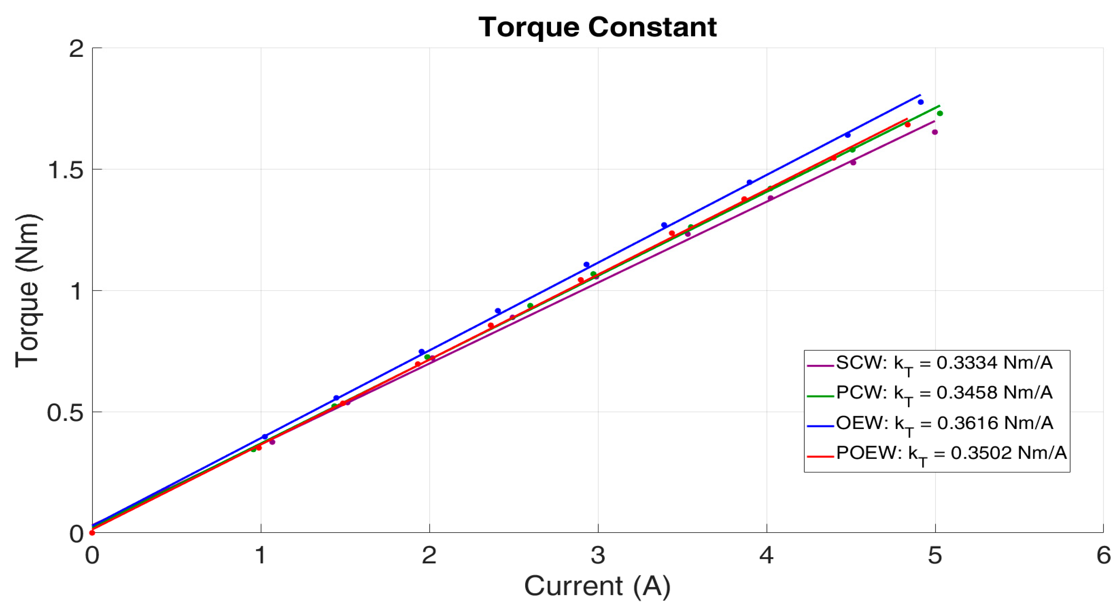
While the proposed winding methods contribute to improving speed performance, they must also maintain the core characteristic of high-torque-density motors—namely torque performance. If torque capability is degraded, the winding configuration would not be a suitable choice. Therefore, it is essential to verify whether torque performance is preserved alongside the speed improvement. To evaluate torque characteristics, the torque constant
, which represents the ratio of output torque to input current, was measured. The results were as follows: OEW: 0.3616 Nm/A > POEW: 0.3502 Nm/A > PCW: 0.3458 Nm/A > SCW: 0.3334 Nm/A, as visualized in
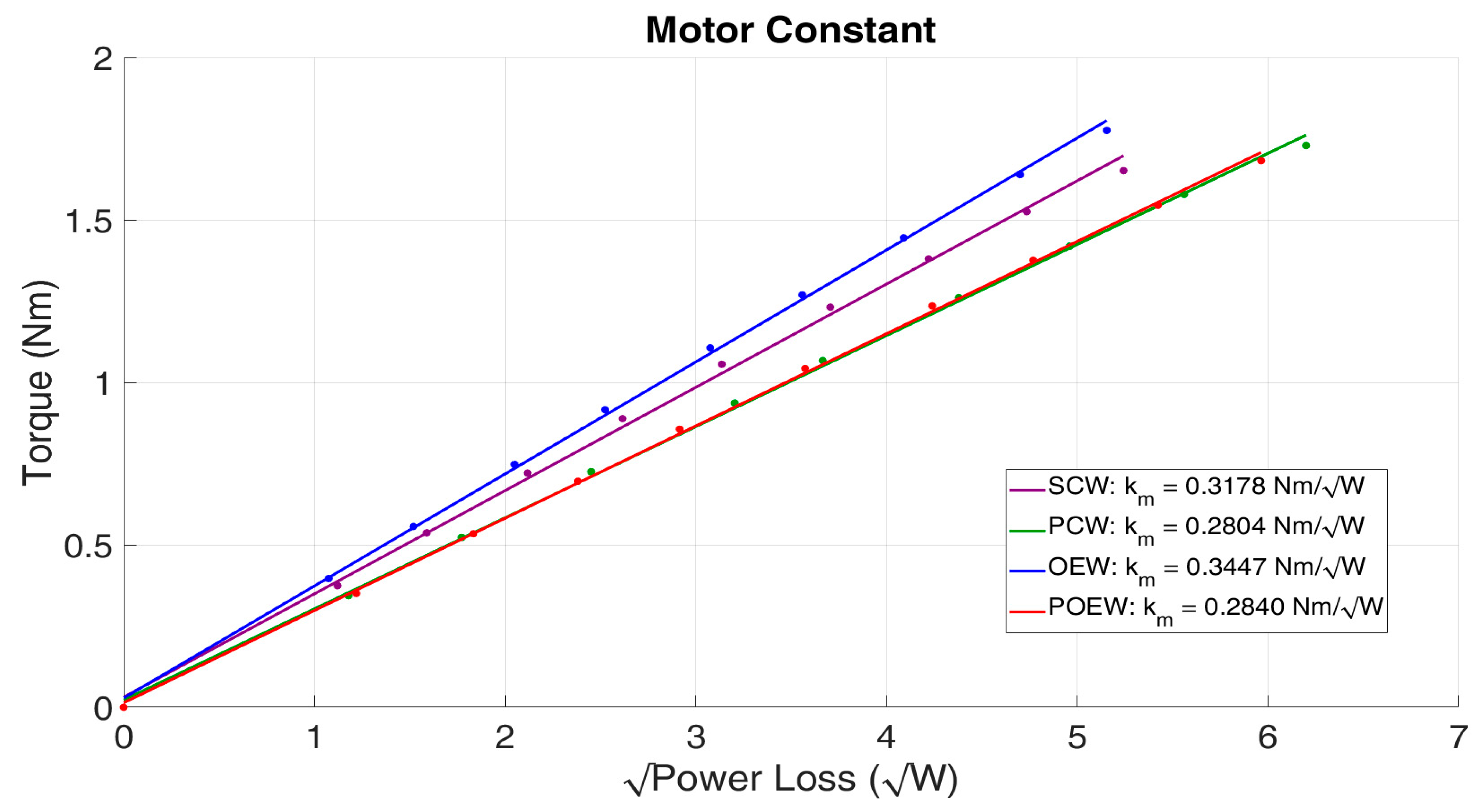
Figure 11. The maximum difference was approximately 0.03 Nm/A, which is not considered a significant performance degradation under the given experimental conditions. However, since phase resistance and current amplitude vary depending on the winding configuration, an additional metric, the motor constant
, was analyzed to comprehensively evaluate torque efficiency with respect to heat generation. The measured results were as follows: OEW: 0.3447
> SCW: 0.3178
> POEW: 0.2840
> PCW: 0.2804
, as shown in
Figure 12. These results indicate that winding configurations incorporating parallel paths tend to exhibit lower motor constants. Although the parallel winding theoretically reduces phase resistance to one-quarter, it requires approximately twice the current in each parallel path to achieve the same torque as a series configuration. Consequently, the total heat generation increases. Specifically, the motor constant of PCW was approximately 11.77% lower than that of SCW and POEW was 17.62% lower than OEW. Therefore, although the torque generation capability
does not differ significantly among the configurations, the motor constant
is relatively lower in parallel winding configurations. This suggests that while parallel winding configurations are advantageous for enhancing speed performance and maintaining torque output, they may reduce overall motor efficiency due to increased heat generation. A summary of all experimental results is provided in
Table 7.
5. Discussion
This study aimed to overcome the inherent limitations of high-torque-density BLDC motors in terms of high-speed performance, particularly under human–robot interaction environments. These motors structurally exhibit high back-electromotive force (back-EMF), and international safety regulations typically restrict their operating voltage to below 50 V, thereby limiting their achievable speed. To address this issue, four winding configurations—SCW, PCW, OEW, and POEW—were proposed and comparatively analyzed. High-torque-density motors are essential for systems such as collaborative robots, wearable robots, rehabilitation robots, and quadruped robots, where both high torque and high-speed performance are required.
Experimental results under a 48 V voltage source demonstrated that the PCW and OEW configurations achieved approximately 1.85 and 1.83 times the maximum speed of SCW, respectively, while the combined POEW configuration achieved a 3.52-fold improvement. These results were obtained solely through winding modifications without altering the rotor or stator structure, demonstrating that the proposed POEW serves as an innovative alternative to overcome the traditional limitations of high-torque-density motors. In terms of torque characteristics, the torque constants () of the four configurations were measured as SCW: 0.3334 Nm/A, PCW: 0.3458 Nm/A, OEW: 0.3616 Nm/A, and POEW: 0.3502 Nm/A, with a maximum deviation of only 0.03 Nm/A, indicating minimal impact on torque generation capability from the winding modifications. On the other hand, the motor constant () showed a slight decrease in parallel winding configurations due to increased current-induced heating, with POEW exhibiting a 10.63% reduction compared to SCW, recorded at 0.2840 .
However, implementing the POEW presents certain technical challenges. Firstly, commercially available motors and dedicated drivers supporting POEW are limited. Secondly, OEW and POEW require three full-bridge inverters, which not only double the number of switching components and associated losses but also increase the overall hardware cost. Thirdly, parallel windings may introduce circulating currents due to resistance and inductance discrepancies between parallel paths, necessitating precise symmetrical design and wiring, which could also lead to increased manufacturing complexity and cost.
Nevertheless, the POEW configuration presents a practical and effective solution for fundamentally overcoming the low-speed limitations of conventional high-torque-density motors in voltage-constrained environments. Future research will focus on analyzing the POEW’s performance under specific load conditions and evaluating inverter losses and thermal characteristics to further enhance the safety, reliability, and dynamic response of robotic actuators.
Author Contributions
Conceptualization, J.P. and H.C.; methodology, J.P. and H.C.; software, J.P.; data curation, J.P. and H.C.; formal analysis, J.P. and H.C.; writing—original draft preparation, J.P.; Visualization C.H.; writing—review and editing, J.P. and H.C.; supervision, H.C.; project administration, H.C.; funding acquisition, H.C. All authors have read and agreed to the published version of the manuscript.
Funding
This work was supported by Incheon National University (International Cooperative) Research Grant in 2020.
Data Availability Statement
Data are contained within the article.
Conflicts of Interest
The authors declare no conflicts of interest.
References
- Pervez, A.; Ryu, J. Safe physical human robot interaction-past, present and future. J. Mech. Sci. Technol. 2008, 22, 469–483. [Google Scholar] [CrossRef]
- Yu, S.; Wang, Z.; Gan, H.; Shi, Q.; Wang, Z.; Xiao, Y.; Zhang, J.; Zhao, J. Quasi-direct drive actuation for a lightweight hip exoskeleton with high backdrivability and high bandwidth. IEEE/ASME Trans. Mechatron. 2020, 25, 1794–1802. [Google Scholar] [CrossRef] [PubMed]
- Seok, S.; Wang, A.; Otten, D.; Kim, S. Actuator design for high force proprioceptive control in fast legged locomotion. In Proceedings of the 2012 IEEE/RSJ International Conference on Intelligent Robots and Systems, Vilamoura, Portugal, 7–12 October 2012; pp. 1970–1975. [Google Scholar]
- Seok, S.; Wang, A.; Chuah, M.Y.M.; Otten, D.; Lang, J.; Kim, S. Design principles for highly efficient quadrupeds and implementation on the MIT Cheetah robot. In Proceedings of the 2013 IEEE International Conference on Robotics and Automation, Karlsruhe, Germany, 6–10 May 2013; pp. 3307–3312. [Google Scholar]
- Seok, S.; Wang, A.; Chuah, M.Y.; Hyun, D.J.; Lee, J.; Otten, D.M.; Lang, J.H.; Kim, S. Design principles for energy-efficient legged locomotion and implementation on the MIT cheetah robot. IEEE/ASME Trans. Mechatron. 2014, 20, 1117–1129. [Google Scholar] [CrossRef]
- Wensing, P.M.; Wang, A.; Seok, S.; Otten, D.; Lang, J.; Kim, S. Proprioceptive actuator design in the MIT cheetah: Impact mitigation and high-bandwidth physical interaction for dynamic legged robots. IEEE Trans. Robot. 2017, 33, 509–522. [Google Scholar] [CrossRef]
- Farve, N.N. Design of a Low-Mass High-Torque Brushless Motor for Application in Quadruped Robotics. Ph.D. Thesis, Massachusetts Institute of Technology, Cambridge, MA, USA, 2012. [Google Scholar]
- Roman, D. Introduction to IEC 60335—Household and similar electrical appliances—Safety. In Proceedings of the 2015 IEEE Symposium on Product Compliance Engineering (ISPCE), Chicago, IL, USA, 18–20 May 2015; pp. 1–6. [Google Scholar]
- Schwartz, M.; Sim, J.; Ahn, J.; Hwang, S.; Lee, Y.; Park, J. Design of the Humanoid Robot TOCABI. In Proceedings of the 2022 IEEE-RAS 21st International Conference on Humanoid Robots (Humanoids), Ginowan, Japan, 28–30 November 2022; pp. 322–329. [Google Scholar]
- Chen, J.; Deng, Z.; Jiang, S. Study of Locomotion Control Characteristics for Six Wheels Driven In-Pipe Robot. In Proceedings of the 2004 IEEE International Conference on Robotics and Biomimetics, Shenyang, China, 22–26 August 2004; pp. 119–124. [Google Scholar]
- Jo, K.-J.; Oh, J.-S. Characteristic analysis of independent 3 phase BLDC motor. Trans. Korean Inst. Power Electron. 2007, 12, 299–304. [Google Scholar]
- Mohanraj, D.; Muthananthguruadoss, S.; Vijayarajan, A.; Rajasekar, V.G.; Chokkalingam, B.; Muthuramalingam, T. A review of BLDC motor: State of art, advanced control techniques, and applications. IEEE Access 2022, 10, 54833–54869. [Google Scholar] [CrossRef]
- Pillay, P.; Krishnan, R. Modeling of permanent magnet motor drives. IEEE Trans. Ind. Electron. 1988, 35, 537–541. [Google Scholar] [CrossRef]
- Pillay, P.; Krishnan, R. Modeling, simulation, and analysis of permanent-magnet motor drives. II. The brushless DC motor drive. IEEE Trans. Ind. Appl. 1989, 25, 274–279. [Google Scholar] [CrossRef]
- An, Q.; Liu, J.; Peng, Z.; Sun, L.; Sun, L. Dual-Space Vector Control of Open-End Winding Permanent Magnet Synchronous Motor Drive Fed by Dual Inverter. IEEE Trans. Power Electron. 2016, 31, 8329–8342. [Google Scholar] [CrossRef]
- Hu, W.; Ruan, C.; Nian, H.; Sun, D. Zero-Sequence Current Suppression Strategy with Common-Mode Voltage Control for Open-End Winding PMSM Drives with Common DC Bus. IEEE Trans. Ind. Electron. 2021, 68, 4691–4702. [Google Scholar] [CrossRef]
- Kumar, N.; Das, A. Analysis of Torque Ripple in Open-End Winding Dual Inverter-Based BLDC Motor Drive System. In Proceedings of the 2023 International Conference on Power Electronics and Energy (ICPEE), Bhubaneswar, India, 3–5 January 2023; pp. 1–5. [Google Scholar]
- Shchur, I.; Turkovskyi, V.; Boichuk, B. Dual Battery Powered Drive System Using an Open-End Winding Brushless DC Motor. In Proceedings of the 2021 IEEE 3rd Ukraine Conference on Electrical and Computer Engineering (UKRCON), Lviv, Ukraine, 26–28 August 2021; pp. 327–332. [Google Scholar]
- Huang, Q.; Luo, L.; Xue, L.-K.; Tang, Y. Research on the Characteristics of Open Winding Brushless DC Motor. In Proceedings of the 2019 22nd International Conference on Electrical Machines and Systems (ICEMS), Harbin, China, 11–14 August 2019; pp. 1–6. [Google Scholar]
- Park, J.; Chang, H. Improving Speed Characteristics of High-Torque-Density Motors for Physical Human–Robot Interaction Using an Independent Three-Phase Winding Structure. Actuators 2024, 13, 161. [Google Scholar] [CrossRef]
- Lee, Y.; Kim, J. Analysis of the three-phase inverter power efficiency of a BLDC motor drive using conventional six-step and inverted pulsewidth modulation driving schemes. Can. J. Electr. Comput. Eng. 2019, 42, 34–40. [Google Scholar] [CrossRef]
- Sun, Q.; Wu, J.; Gan, C.; Si, J.; Guo, Y. Modular full-bridge converter for three-phase switched reluctance motors with integrated fault-tolerance capability. IEEE Trans. Power Electron. 2018, 34, 2622–2634. [Google Scholar] [CrossRef]
- Petrella, R.; Tursini, M.; Peretti, L.; Zigliotto, M. Speed measurement algorithms for low-resolution incremental encoder equipped drives: A comparative analysis. In Proceedings of the 2007 International Aegean Conference on Electrical Machines and Power Electronics, Bodrum, Turkey, 10–12 September 2007; IEEE: Piscataway, NJ, USA, 2007. [Google Scholar]
Figure 1.
Developed motor.
Figure 1.
Developed motor.
Figure 2.
(a) Equivalent circuit of SCW BLDC motor; (b) conduction system of SCW BLDC motor (two-phase conduction).
Figure 2.
(a) Equivalent circuit of SCW BLDC motor; (b) conduction system of SCW BLDC motor (two-phase conduction).
Figure 3.
(a) Equivalent circuit of PCW BLDC motor; (b) Conduction system of PCW BLDC motor (two-phase conduction).
Figure 3.
(a) Equivalent circuit of PCW BLDC motor; (b) Conduction system of PCW BLDC motor (two-phase conduction).
Figure 4.
(a) Equivalent circuit of OEW BLDC motor; (b) Conduction system of OEW BLDC motor (single-phase conduction).
Figure 4.
(a) Equivalent circuit of OEW BLDC motor; (b) Conduction system of OEW BLDC motor (single-phase conduction).
Figure 5.
(a) Equivalent circuit of POEW BLDC motor; (b) conduction system of POEW BLDC motor (single-phase conduction).
Figure 5.
(a) Equivalent circuit of POEW BLDC motor; (b) conduction system of POEW BLDC motor (single-phase conduction).
Figure 6.
SCW and PCW BLDC motor inverter circuit and connecting schematic.
Figure 6.
SCW and PCW BLDC motor inverter circuit and connecting schematic.
Figure 7.
OEW and POEW BLDC motor inverter circuit and connecting schematic.
Figure 7.
OEW and POEW BLDC motor inverter circuit and connecting schematic.
Figure 8.
Experiment layout.
Figure 8.
Experiment layout.
Figure 9.
Top view of the experimental test bed.
Figure 9.
Top view of the experimental test bed.
Figure 10.
Comparison of no-load motor speed characteristics under different winding configurations.
Figure 10.
Comparison of no-load motor speed characteristics under different winding configurations.
Figure 11.
Comparison of torque constants for different winding configurations.
Figure 11.
Comparison of torque constants for different winding configurations.
Figure 12.
Comparison of motor constants for different winding configurations.
Figure 12.
Comparison of motor constants for different winding configurations.
Table 1.
Developed motor characteristic parameters (SCW BLDC motor).
Table 1.
Developed motor characteristic parameters (SCW BLDC motor).
Phase Resistance
] | Torque Const.
] | Nominal Torque
] | Torque Density
] | Weight
] | No Load Speed
] | Power
] |
|---|
| 0.55 | 0.32 | 2.2 | 3.78 | 582.4 | ] | 280 |
Table 2.
SCW and PCW BLDC motor inverter switching sequence.
Table 2.
SCW and PCW BLDC motor inverter switching sequence.
| Direction | Operating Range | Hall Sensor | Switching Signal |
|---|
| Degree | Interrupt | HA | HB | HC | A1 | A2 | B1 | B2 | C1 | C2 |
|---|
| Forward | 0~60 | HA↑ | 1 | 1 | 0 | 0 | 0 | 1 | 0 | 0 | PWM |
| 60~120 | HB↓ | 1 | 0 | 0 | 1 | 0 | 0 | 0 | 0 | PWM |
| 120~180 | HC↑ | 1 | 0 | 1 | 1 | 0 | 0 | PWM | 0 | 0 |
| 180~240 | HA↓ | 0 | 0 | 1 | 0 | 0 | 0 | PWM | 1 | 0 |
| 240~300 | HC↑ | 0 | 1 | 1 | 0 | PWM | 0 | 0 | 1 | 0 |
| 300~360 | HB↓ | 0 | 0 | 1 | 0 | PWM | 1 | 0 | 0 | 0 |
| Reverse | 0~60 | HA↑ | 1 | 0 | 1 | 0 | PWM | 1 | 0 | 0 | 0 |
| 60~120 | HC↓ | 1 | 0 | 0 | 0 | PWM | 0 | 0 | 1 | 0 |
| 120~180 | HB↑ | 1 | 1 | 0 | 0 | 0 | 0 | PWM | 1 | 0 |
| 180~240 | HA↓ | 0 | 1 | 0 | 1 | 0 | 0 | PWM | 0 | 0 |
| 240~300 | HC↑ | 0 | 1 | 1 | 1 | 0 | 0 | 0 | 0 | PWM |
| 300~360 | HB↓ | 0 | 0 | 1 | 0 | 0 | 1 | 0 | 0 | PWM |
Table 3.
OEW and POEW BLDC motor inverter switching sequence.
Table 3.
OEW and POEW BLDC motor inverter switching sequence.
| Direction | Operating Range | Hall Sensor | Switching Signal |
|---|
| Degree | Interrupt | HA | HB | HC | A1 | A2 | A3 | A4 | B1 | B2 | B3 | B4 | C1 | C2 | C3 | C4 |
|---|
| Forward | 0~60 | HA↑ | 1 | 1 | 0 | 0 | 0 | 0 | 0 | 1 | 0 | 0 | PWM | 0 | PWM | 1 | 0 |
| 60~120 | HB↓ | 1 | 0 | 0 | 1 | 0 | 0 | PWM | 0 | 0 | 0 | 0 | 0 | PWM | 1 | 0 |
| 120~180 | HC↑ | 1 | 0 | 1 | 1 | 0 | 0 | PWM | 0 | PWM | 1 | 0 | 0 | 0 | 0 | 0 |
| 180~240 | HA↓ | 0 | 0 | 1 | 0 | 0 | 0 | 0 | 0 | PWM | 1 | 0 | 1 | 0 | 0 | PWM |
| 240~300 | HC↑ | 0 | 1 | 1 | 0 | PWM | 1 | 0 | 0 | 0 | 0 | 0 | 1 | 0 | 0 | PWM |
| 300~360 | HB↓ | 0 | 0 | 1 | 0 | PWM | 1 | 0 | 1 | 0 | 0 | PWM | 0 | 0 | 0 | 0 |
| Reverse | 0~60 | HA↑ | 1 | 0 | 1 | 0 | PWM | 1 | 0 | 1 | 0 | 0 | PWM | 0 | 0 | 0 | 0 |
| 60~120 | HC↓ | 1 | 0 | 0 | 0 | PWM | 1 | 0 | 0 | 0 | 0 | 0 | 1 | 0 | 0 | PWM |
| 120~180 | HB↑ | 1 | 1 | 0 | 0 | 0 | 0 | 0 | 0 | PWM | 1 | 0 | 1 | 0 | 0 | PWM |
| 180~240 | HA↓ | 0 | 1 | 0 | 1 | 0 | 0 | PWM | 0 | PWM | 1 | 0 | 0 | 0 | 0 | 0 |
| 240~300 | HC↑ | 0 | 1 | 1 | 1 | 0 | 0 | PWM | 0 | 0 | 0 | 0 | 0 | PWM | 1 | 0 |
| 300~360 | HB↓ | 0 | 0 | 1 | 0 | 0 | 0 | 0 | 1 | 0 | 0 | PWM | 0 | PWM | 1 | 0 |
Table 4.
Structural and electrical characteristics of SCW, PCW, OEW, and POEW.
Table 4.
Structural and electrical characteristics of SCW, PCW, OEW, and POEW.
| | Neutral Point | Conduction System | | | | | Back-EMF Constant | Inverter Topology |
|---|
| SCW | Present | Two-phase | 1 | 18 | 0.55 | 802.4 | | Six-step inverter |
| PCW | Present | Two-phase | 2 | 9 | 0.19 | 200.6 | | Six-step inverter |
| OEW | Absent | Single-phase | 1 | 18 | 0.55 | 802.4 | | Three full-bridge inverters |
| POEW | Absent | Single-phase | 2 | 9 | 0.19 | 200.6 | | Three full-bridge inverters |
Table 5.
Speed calculation parameters for the M method.
Table 5.
Speed calculation parameters for the M method.
| | Number of Poles | PPR | [s] |
|---|
| BLDC Motor | 13 | 78 | 0.04 |
Table 6.
Comparison of motor speed and ripple under different winding configurations at 94% PWM duty.
Table 6.
Comparison of motor speed and ripple under different winding configurations at 94% PWM duty.
| | SCW | PCW | OEW | POEW |
|---|
| Speed [RPM] | 1214.4 | 2312.7 | 2331.2 | 4273.8 |
| Max Ripple [RPM] | 19 | 19 | 20 | 19 |
Table 7.
Comparison of torque constant and motor constant for each winding configuration.
Table 7.
Comparison of torque constant and motor constant for each winding configuration.
| | SCW | PCW | OEW | POEW |
|---|
| | 0.3334 | 0.3458 | 0.3616 | 0.3502 |
| | 0.3178 | 0.2804 | 0.3447 | 0.2840 |
| Disclaimer/Publisher’s Note: The statements, opinions and data contained in all publications are solely those of the individual author(s) and contributor(s) and not of MDPI and/or the editor(s). MDPI and/or the editor(s) disclaim responsibility for any injury to people or property resulting from any ideas, methods, instructions or products referred to in the content. |
© 2025 by the authors. Licensee MDPI, Basel, Switzerland. This article is an open access article distributed under the terms and conditions of the Creative Commons Attribution (CC BY) license (https://creativecommons.org/licenses/by/4.0/).


