Article

Preparation and Characterization of HIR Multi-Layer Abrasion-Resistant Coating for Hydraulic Concrete


1
State Key Laboratory of Silicate Materials for Architectures, Wuhan University of Technology, Wuhan 430070, China
2
Mid-Route Source of South-to-North Water Transfer Co., Ltd., Danjiangkou 442700, China
3
Material and Engineering Structure Department, Changjiang River Scientific Research Institute, Wuhan 430010, China
*
Authors to whom correspondence should be addressed.
Buildings 2026, 16(9), 1799; https://doi.org/10.3390/buildings16091799
Submission received: 2 April 2026 / Revised: 19 April 2026 / Accepted: 27 April 2026 / Published: 1 May 2026
(This article belongs to the Topic Advanced Composite Materials)

Abstract

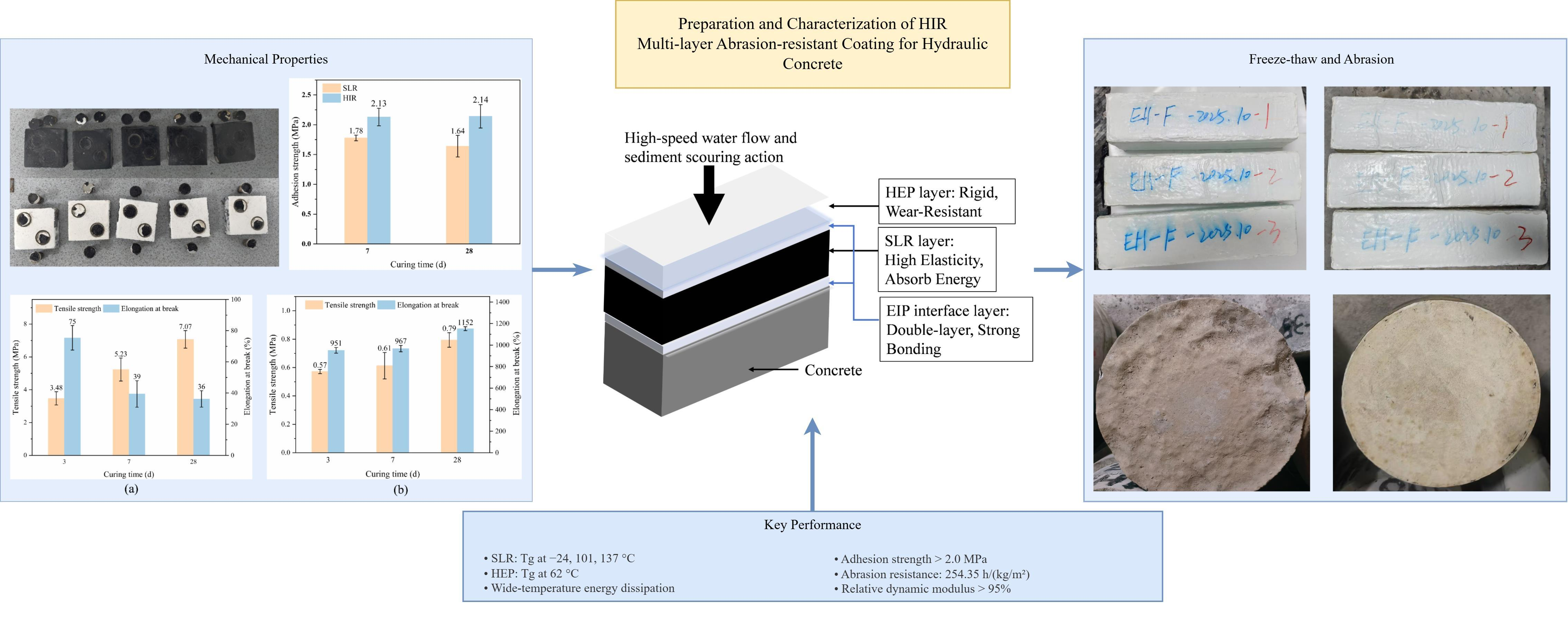
Hydraulic concrete suffers severe damage from high-velocity sand-bearing water flow. Traditional single-layer coating materials struggle to simultaneously satisfy the requirements of strong adhesion, high abrasion resistance, and long-term durability. In this study, a functionally graded multilayer composite coating system, designated HIR (Hybrid Epoxy–Interfacial Primer–Rubber), was developed. The HIR system comprises a hybrid acrylic–epoxy resin (HEP) top layer, a modified epoxy-based interfacial primer (EIP), and a sprayed liquid rubber (SLR) middle layer, realizing synergistic enhancement of interfacial bonding, deformation adaptability, and abrasion resistance. The results showed that the HIR achieved an adhesion strength exceeding 2.0 MPa to concrete. The HEP exhibited an elongation at break exceeding 30%, while the SLR showed an elongation at break higher than 1000%. The anti-abrasion strength of the HIR-coated concrete reached 254.35 h/(kg/m2), which is 15 times that of uncoated concrete. Moreover, the coated concrete maintained a relative dynamic elastic modulus above 95% after 300 freeze–thaw cycles. DMA revealed multiple glass transition temperatures in both SLR (24 °C, 101 °C, 137 °C) and HEP (62 °C), enabling effective energy dissipation over a wide temperature range. Through interlayer property matching and synergistic enhancement, the HIR significantly enhances both abrasion resistance and freeze–thaw durability of hydraulic concrete.

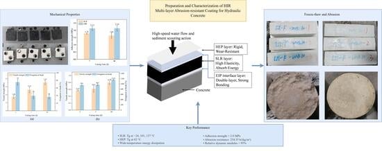
Graphical Abstract

1. Introduction

Hydraulic concrete structures (e.g., dam spillways, hydropower station diversion tunnels, and water conveyance galleries) are susceptible to cracking, pitting, microbial growth, and weathering under long-term erosion by high-velocity sand-laden flows, as well as abrasion, cavitation damage, and chemical corrosion. These deterioration mechanisms significantly reduce service life and compromise the safe operation and appearance of engineering projects [1,2,3,4]. Among them, abrasion is the primary factor that triggers other forms of damage [5]. The wear rate is closely related to concrete mix proportion, porosity, flow velocity, sediment content, and particle size [6,7].
Current anti-abrasion protection measures for concrete include corrosion inhibitors [8], surface protective coatings [9], and superhydrophobic modification [10,11]. Among these, high-performance coating technology, as an economical and effective method, has become a research and application focus. By enhancing the erosion resistance of concrete surfaces, it improves structural durability.
Protective coatings for concrete are broadly classified into organic coatings, inorganic coatings, and organic/inorganic nanocomposite coatings. Organic coatings, such as epoxy resins [12,13], polyurea [14,15], polyurethane [16], and acrylics [17], typically possess a dense structure that effectively blocks the ingress of molecules, ions, and water, thereby significantly improving concrete abrasion resistance. Epoxy resin materials, owing to their excellent adhesion, high strength, low shrinkage, and strong heat and corrosion resistance, have been widely used in hydraulic engineering, especially in highly corrosive environments such as chemical plants and marine facilities [18,19]. However, cured epoxy resins form a three-dimensional network with high crosslinking density and substantial internal stress, leading to high brittleness, easy cracking, and poor toughness [12].
To address these drawbacks, various modification strategies have been explored. Sushil et al. [20] incorporated SiO2 nanoparticles (ca. 15 nm) into an epoxy system via ultrasonic dispersion. With 4 wt.% silica nanoparticles, the tensile strength, Young’s modulus, and toughness increased by approximately 44%, 58%, and 144%, respectively, compared to unmodified epoxy. Ge et al. [21] used epoxidized hydroxyl-terminated polybutadiene (EHTPB) to toughen epoxy resin; the activation energy decreased, and the elongation at break reached 120%. Xu et al. [22] synthesized a polyurethane-modified epoxy resin using interpenetrating polymer network (IPN) technology and flexible segment design. At an A/B component ratio of 7:3, the modified epoxy achieved a tensile strength exceeding 15 MPa and an elongation at break higher than 20%, realizing synergistic enhancement of strength and toughness.
Single-layer coating systems are often constrained by their inherent properties and struggle to simultaneously meet the conflicting requirements of strong adhesion, high abrasion resistance, and long-term durability, which remains a key challenge for engineering applications. To overcome these limitations in performance adaptability, interfacial stability, and environmental adaptability, this study proposes a synergistic strategy that integrates a “multilayer composite structure” with a “broad-temperature gradient loss” concept. A functionally graded multilayer composite coating system (Hybrid Epoxy–Interfacial Primer–Rubber, HIR), featuring an “interface-structure-function” multidimensional coupling, was constructed to enhance the abrasion resistance of concrete under wide-temperature and multi-factor coupled environments. The originality of this work lies in (i) the rational design of a soft-hard multilayer structure with gradient Tg; (ii) the use of a sprayed liquid rubber (SLR) layer with ultra-high elongation (>1000%) and multiple Tg for broad-temperature energy dissipation; (iii) the synergistic coupling of a rigid hybrid epoxy resin top layer and a flexible SLR middle layer, which breaks the conventional bottleneck of epoxy brittleness. The objectives are to evaluate the interfacial bonding, mechanical properties, freeze–thaw durability, and impact-abrasion resistance of the HIR system and to elucidate the underlying energy dissipation mechanisms via DMA and fractography.
Specifically, to address the insufficient flexibility and poor environmental friendliness of conventional solvent-based epoxy coatings, a waterborne hybrid acrylic–epoxy resin (HEP) was developed as the top layer via hybrid emulsion polymerization, combining high strength with excellent flexibility. The intermediate layer employed a sprayed liquid rubber (SLR) formulated from modified anionic emulsified asphalt and rubber polymers. It forms a seamless, “skin-like” waterproof and corrosion-resistant layer through rapid ambient-temperature curing of two-component materials, integrating asphalt’s sealing properties with rubber’s high elasticity. The SLR layer effectively accommodates concrete cracking and structural deformation, offering ultra-high elasticity, good heat resistance, and non-toxic, pollution-free characteristics [23,24]. The interface layer material was a modified epoxy-based interfacial primer (EIP) that ensures strong adhesion between the coating system, the concrete substrate, and interlayer interfaces. Through this novel multilayer functional gradient Hybrid Epoxy–Interfacial Primer–Rubber (HIR) coating system and its interfacial coupling synergistic mechanism, both the abrasion resistance and freeze–thaw durability of hydraulic concrete are synergistically improved. This paper systematically evaluates the comprehensive performance and application potential of the HIR coating system and explores the relationship between its microstructure and properties.

2. Materials and Methods

2.1. Raw Materials

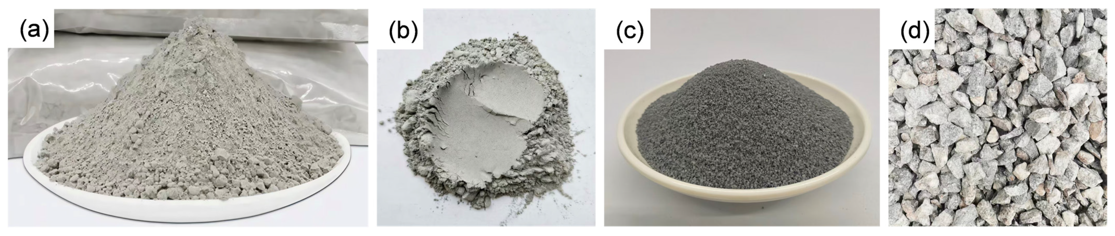
The strength grade of the concrete used in the test is C40, and the mix proportions of different components are shown in Table 1. The details of the materials are as follows: Cement: moderate-heat Portland cement of strength grade 42.5, Taiyuan Shitou Cement Co., Ltd. (Taiyuan, China); fly ash: Grade I, Hebei Huisun Mining Co., Ltd. (Shijiazhuang, China); Sand: manufactured sand with fineness modulus of 2.44; Coarse aggregate: crushed granite with particle sizes of 5–20 mm and 20–40 mm mixed at a mass ratio of 9:11; Water-reducing agent: acrylic type X404, with a water reduction rate exceeding 30%, capable of reducing hydration heat, produced by Mapei S.P.A. (Milan, Italy); Air-entraining agent: DH9, used in combination with the water-reducing agent to improve workability and freeze–thaw durability of concrete, Hebei Shengtong Building Materials Technology Co., Ltd. (Shijiazhuang, China). The appearance of cement, fly ash, sand, and granite crushed stone is shown in Figure 1. The main chemical compositions of cement and fly ash are presented in Table 2 and Table 3, respectively.
Water-based epoxy curing agent: Guangzhou Yike New Material Technology Co., Ltd. (Guangzhou, China); Modified epoxy-based interface agent: Shenzhen Jiadida New Material Technology Co., Ltd. (Shenzhen, China); Matrix asphalt: PetroChina Karamay Petrochemical Company (Karamay, China); Chloroprene latex: Shanghai Zhengshang Chemical Technology Co., Ltd. (Shanghai, China); Modified styrene-butadiene rubber: Shandong Haifang Rubber Technology Co., Ltd. (Zibo, China); Bisphenol A epoxy resin: E44, Guangzhou Dongfeng Chemical Industry Co., Ltd. (Guangzhou, China); Ammonium nonylphenol ether sulfate (AESA): Nanjing Baiju Science and Technology Co., Ltd. (Nanjing, China). Butyl acrylate (BA), styrene (St), ammonium persulfate (APS), Non-ionic surfactant Triton X-100 buffer (1%), anionic surfactants Sodium 3-(allyloxy)-2-hydroxypropane-1-sulfonate (HAPS, 40 wt.%), propylene glycol methyl ether (PM), nano-silicon dioxide (particle size approximately 15 nm, purity 99.5%), sodium hydroxide (NaOH), aqueous ammonia (25–28%) are produced by Shanghai Macklin Biochemical Co., Ltd. (Shanghai, China), all reagents are analytical grade; Deionized water: self-made.

2.2. Preparation of Material

2.2.1. Preparation of SLR Intermediate Layer Material

First, 50 g of water and 20 g of nano-silica were added to a beaker and stirred with a glass rod to form a paste. The mixture was then ultrasonically dispersed for 15 min to ensure the absence of agglomerates. After standing to eliminate bubbles, the paste was set aside for later use. Meanwhile, 500 g of base asphalt was heated to 140–160 °C under continuous stirring. Once completely melted, 20 g of modified styrene-butadiene rubber was added, and the mixture was subjected to high-speed shear emulsification (3000 r/min) using a colloid mill for 1 h to obtain an emulsified asphalt. Subsequently, the emulsified asphalt, 150 g of chloroprene latex, 10 g of thickener, the pre-dispersed nano-silica, 4 g of defoamer, and aqueous ammonia (to adjust the pH to 8.0) were stirred at a low speed (400 r/min) for 30 min to form a stable emulsion, which served as Component A of the coating. Component B (curing agent) was a 20 wt.% sodium hydroxide aqueous solution prepared by dissolving NaOH in water under agitation. Components A and B were mixed at a mass ratio of 10:1 using a spray-mixing nozzle. Upon spraying, the mixture cured to form a film within 3–5 s.

2.2.2. Preparation of HEP Surface Layer Material

100 g of deionized water and 4 g of a composite emulsifier (HAPS:AESA:X-100 = 1:1:1 by mass, i.e., approximately 1.33 g each) were placed into a three-necked flask. Then, 25 g of epoxy resin (E44), 30 g of butyl acrylate, 30 g of styrene, and 1 g of aqueous ammonia were slowly added. The mixture was pre-emulsified under high-speed stirring (1000 r/min) to obtain a pre-emulsion. Subsequently, 1/4 of the pre-emulsion was transferred into a four-necked flask equipped with a stirrer, a condenser, and a thermometer. The content was heated to approximately 80 °C under constant-speed stirring (300 r/min), and 0.5 g of ammonium persulfate was added dropwise as an initiator to start the polymerization. After about 1 h, the remaining pre-emulsion and 1 g of ammonium persulfate were added dropwise, and the reaction continued for 3–4 h. The temperature was then raised to 80–90 °C and maintained for an additional 1 h. After the reaction was completed, the mixture was cooled to 40 °C, and an appropriate amount of aqueous ammonia was added to adjust the pH to 7.0, yielding an aqueous hybrid-modified epoxy emulsion.
10 g of propylene glycol methyl ether was added to the hybrid-modified epoxy emulsion and mixed uniformly to serve as Component A of the hybrid-modified epoxy coating. Meanwhile, 20 g of an amine curing agent, 1 g of defoamer, 60 g of water, and 19 g of pigments were mixed under high-speed stirring (3000 r/min) for 30 min to form Component B. Components A and B were mixed homogeneously at a mass ratio of 2:1. The mixture was allowed to stand for several minutes to eliminate bubbles. After spraying, it cured to form a film within 24 h.

2.3. Preparation of Specimen

The concrete specimens were prepared as follows. Before casting, the inner surface of the mixer was cleaned and kept moist, while the molds were cleaned and uniformly coated with a release agent on the inner surfaces to facilitate demolding. Cement, fly ash, coarse aggregate, and fine aggregate were weighed according to the designed mix proportions. After dry mixing, the water-reducing agent, which had been pre-dissolved in water, was added, and the mixture was thoroughly stirred until a proper workability was achieved. Subsequently, the air-entraining agent was added, and mixing continued to ensure a uniform distribution of air bubbles. The specimens were then cured in a standard curing room for 28 days under conditions of 20 ± 2 °C and relative humidity no less than 95%.
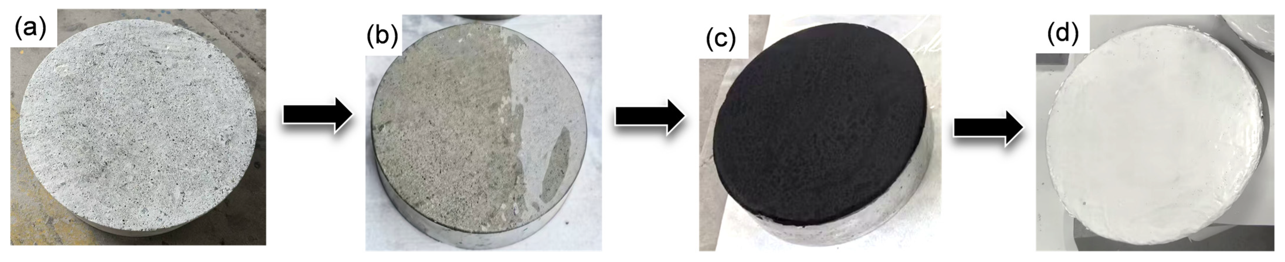
Before applying the coating materials, the surface of each concrete specimen was ground using a grinding machine, then washed with water, dried, and set aside. The coating was applied on the concrete surface in the following sequence. First, a thin layer of EIP interfacial primer was applied. After the primer became tack-free, the SLR middle layer (black) was uniformly sprayed using a spray gun to a controlled dry film thickness of 2 mm. After 7 days of curing, another layer of EIP interfacial primer was brushed onto the SLR layer. Finally, the HEP top layer (white) was sprayed to a dry film thickness of 1 mm. The coated specimens are shown in Figure 2. They were cured for 28 days under standard test conditions (23 ± 2 °C and 50 ± 5% relative humidity) before performance testing. Based on the densities of the SLR (1.0 g/mL) and HEP (1.1 g/mL) materials, the theoretical mass of the required coating was calculated from the surface area of the concrete substrate. The actual film thickness was verified using a hexagonal wet-film comb by randomly measuring three points on each specimen.

2.4. Tests and Characterization

Adhesion performance analysis: The adhesion strength was tested in accordance with GB/T 16777-2008 “Test methods for building waterproofing coatings” [25]. The specimens were cement mortar blocks with dimensions of 70 mm × 70 mm × 20 mm. Five parallel specimens were tested for each coating system (SLR and HIR), and the average adhesion strength was calculated and reported to an accuracy of 0.01 MPa.
Tensile mechanical property analysis: Tensile and elongation at break tests were conducted using a universal testing machine (AG-IC, 100 kN, Shimadzu Corporation, Kyoto, Japan) in accordance with the GB/T 16777-2008 standard. The specimens were Type I dumbbell-shaped with a total length of 115 mm, a narrow-section length of 33 mm, a narrow-section width of 6 mm, and a gauge length of 25 mm. Five parallel specimens were tested for each material. The tensile rate for HEP was 200 mm/min, and for SLR it was 500 mm/min.
FTIR analysis: Fourier transform infrared spectroscopy (FTIR, Nicolet 6700, Thermo Fisher Scientific, Madison, WI, USA) was employed to determine the chemical composition and structure of HEP and SLR. The spectra were recorded over a wavenumber range of 4000 cm−1 to 400 cm−1 with a resolution of 4 cm−1 and 32 scans.
FE-SEM analysis: The fracture morphology of the coatings after tensile testing was observed using a field emission scanning electron microscope (FE-SEM, Zeiss Ultra Plus, Carl Zeiss, Oberkochen, Germany).
DMA: Dynamic mechanical analysis (DMA, 8000, PerkinElmer, Inc., Waltham, MA, USA) was performed in tensile mode to measure the glass transition temperature (Tg) of the coating materials. Specimen dimensions were 50 mm × 6 mm × 2 mm. The test temperature range was −100 °C to 200 °C at a heating rate of 3 °C/min, with a frequency of 1 Hz, and a constant amplitude of 10 μm. The storage modulus (E’) and loss factor (tanδ) were recorded as functions of temperature.
Permeability resistance test: The test was performed according to the stepwise pressurization method described in SL/T 352-2020 “Test code for hydraulic concrete” [26]. Specimens were truncated cones with an upper diameter of 175 mm, a lower diameter of 185 mm, and a height of 150 mm. Six parallel specimens were tested per group. The test apparatus was an automatic pressurization concrete permeameter (HP-4.0, Shanghai Leiyun Test Instrument Manufacturing Co., Ltd., Shanghai, China). Before testing, the specimens were sealed with a mixture of paraffin and rosin and then placed into the mold sleeve. During the test, water pressure was applied stepwise, starting from 0.1 MPa, with each pressure level maintained for 8 h. The end face of each specimen was continuously observed for water seepage. If leakage occurred at the specimen periphery, that specimen was retested. When water seepage appeared on the surface of three specimens, the corresponding pressure was recorded, and the test was terminated.
Freeze–thaw performance test: The test was conducted according to the rapid freezing method (−18 °C to 5 °C cycle) specified in GB/T 50082-2024 “Standard for test methods of long-term performance and durability of concrete” [27]. Specimens were prisms of 100 mm × 100 mm × 400 mm, with three parallel specimens per group. The apparatus consisted of a concrete rapid freeze–thaw testing machine (TDRF-2, Tianjin Luye Experimental Instrument Factory, Tianjin, China) and a dynamic elastic modulus tester for concrete (MIN-011-0-3, Tianjin Luye Experimental Instrument Factory, Tianjin, China). After every 25 freeze–thaw cycles, the specimens were removed to measure their natural vibration frequency. The specimens were rinsed with running water, weighed, and photographed before being returned to the test. The mass loss and relative dynamic elastic modulus of the specimens were calculated. The test was terminated when the relative dynamic elastic modulus fell below 60% of its initial value, and the test data were collected. The relative dynamic elastic modulus was calculated using Equation (1).
P n = f n 2 f 0 2 × 100 %
where P n is the relative dynamic elastic modulus after n freeze–thaw cycles, %; f 0 is the natural vibration frequency before the freeze–thaw test, Hz; f n is the natural vibration frequency after n freeze–thaw cycles, Hz.
Abrasion resistance test: The test was performed using the underwater steel ball method described in DL/T 5150-2017 “Test code for hydraulic concrete” [28] and SL/T 352-2020 “Test code for hydraulic concrete”. Specimens were Φ 300 mm × h 100 mm, with three parallel specimens per group. Before testing, the specimens were immersed in water for 48 h, then removed and weighed under a saturated surface-dry condition to determine their initial mass. The rotation speed of the shaft was set to 4000 r/min. Every 24 h, water was added to the steel cylinder to restore the original water level. After a cumulative abrasion time of 48 h, the specimens were removed, and the mass change was measured. The anti-abrasion strength was calculated using Equation (2):
f α = TA M T
where f α is the anti-abrasion strength, i.e., the time required to abrade a unit mass per unit area, h/(kg/m2); T is the total test duration, h; A is the abraded area of the specimen, m2; M T is the cumulative mass loss of the specimen after abrasion for time T, kg.
The wear rate was calculated using Equation (3):
L = M 1 M 2 M 1
where L is the wear rate, %; M 1 is the specimen mass before the test, kg; M 2 is the specimen mass after the test, kg.
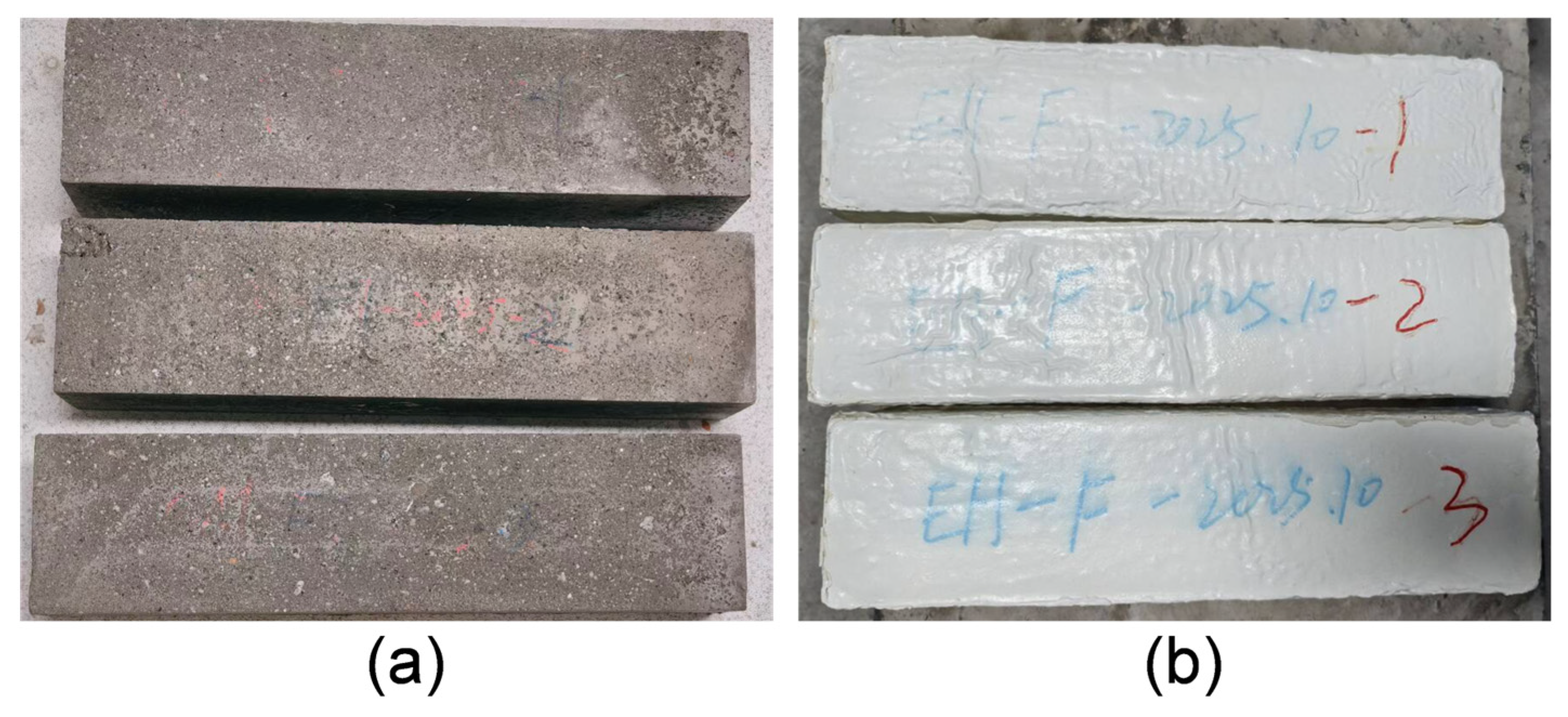
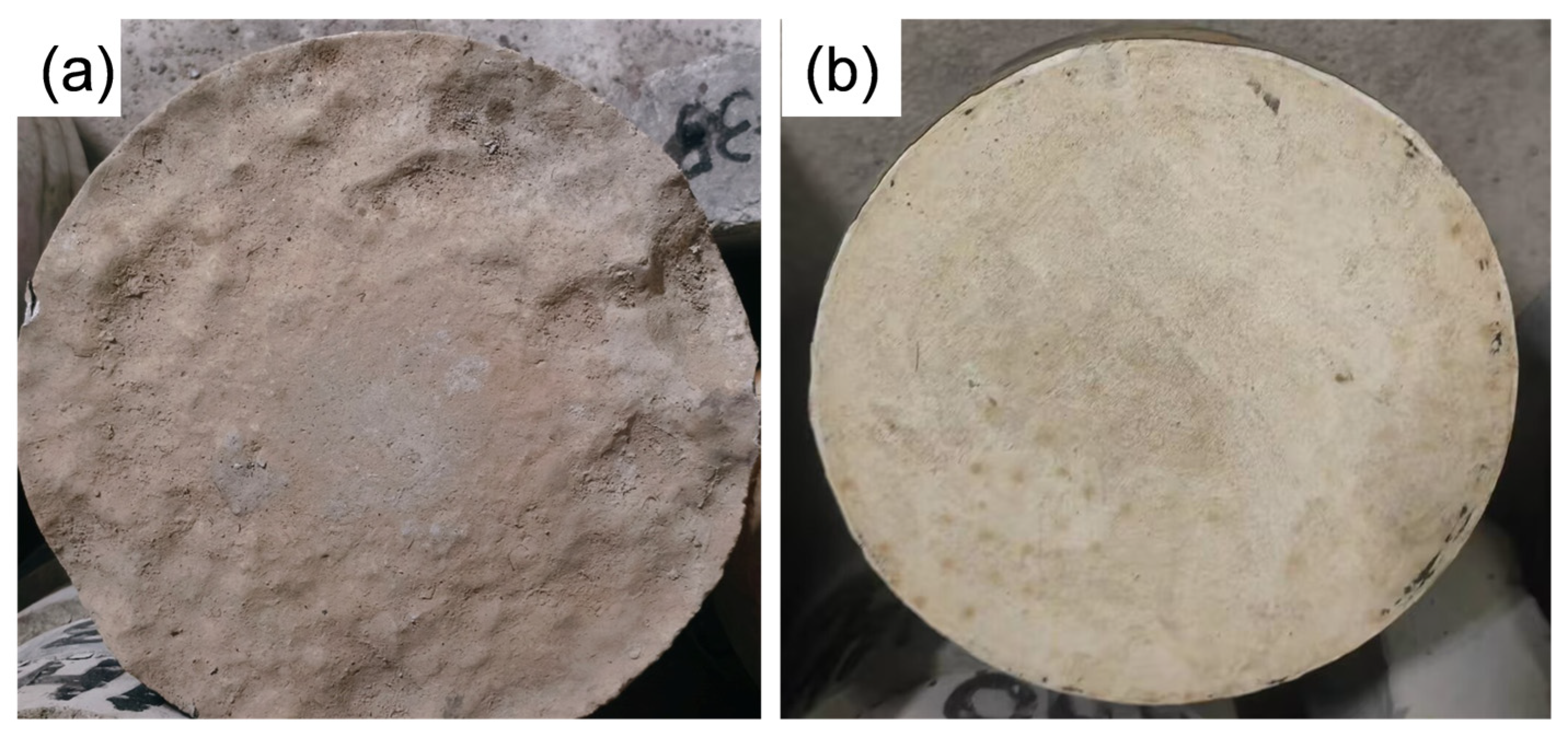
Figure 3 and Figure 4 show the surface photographs of the specimens after the freeze–thaw and abrasion tests, respectively. The relevant performance test results of the coating materials are presented in Table 4.

3. Results and Discussion

3.1. Mechanical Properties Analysis

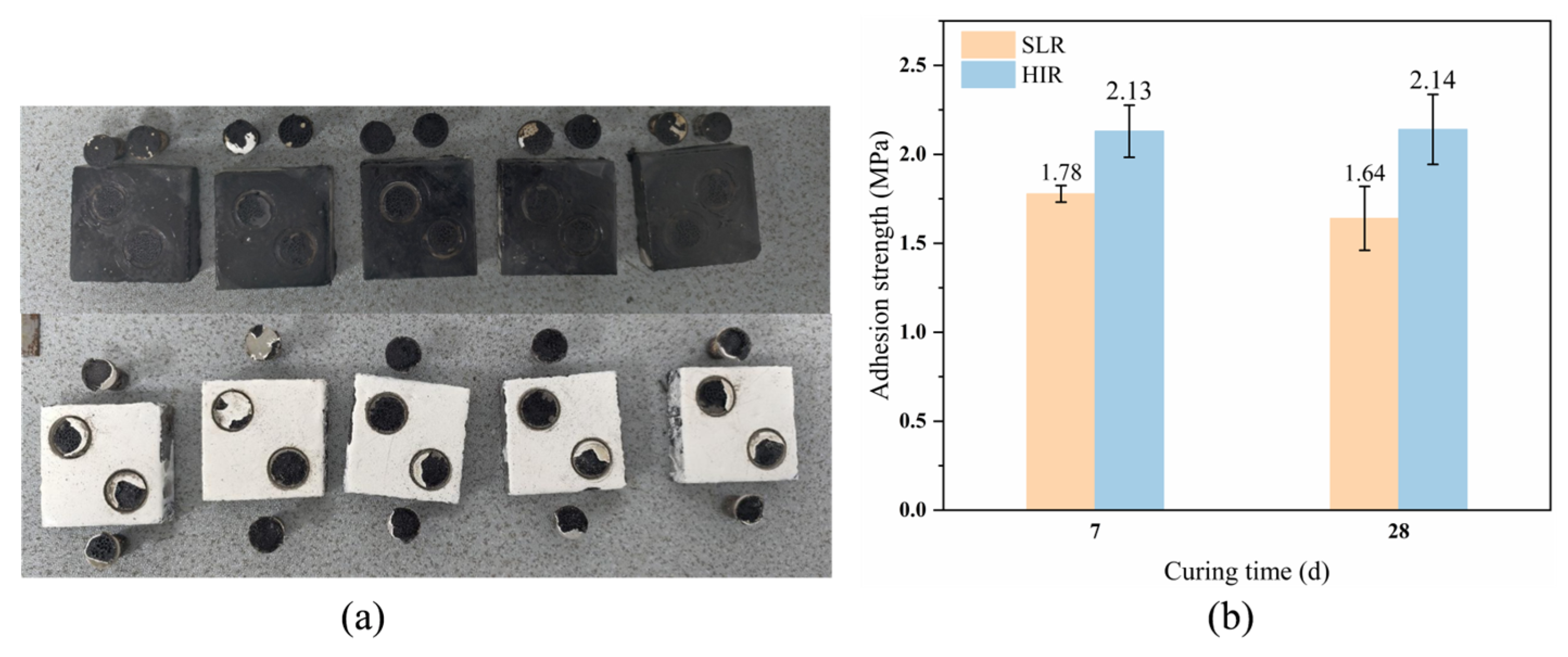
The adhesion performance of the SLR coating and the HIR composite coating to the concrete substrate is presented in Figure 5. As shown in Figure 5a, the failure occurred within the coating layer (cohesive failure), indicating that the interfacial adhesion strength between the SLR layer and the concrete substrate, as well as between the constituent layers of the HIR system, exceeds the cohesive strength of the coating materials themselves. Figure 5b shows that the adhesion strength of the SLR coating at both 7 days and 28 days exceeds 1.5 MPa, with only a slight variation with curing age. This suggests that the adhesion performance of the SLR coating stabilizes by 7 days. The HIR composite coating exhibits an adhesion strength exceeding 2.0 MPa, demonstrating superior interfacial adhesion.
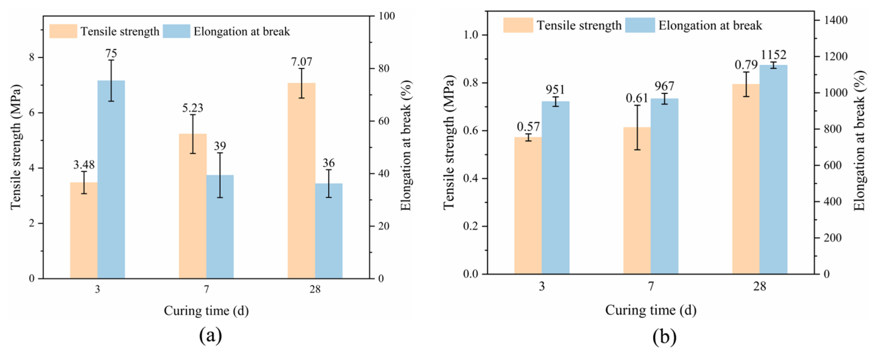
Figure 6a illustrates the tensile properties of the HEP coating at 3, 7, and 28 days of curing. With increasing curing age, the tensile strength of HEP gradually increases, whereas the elongation at break decreases, though it remains above 30%. At 3 days, the tensile strength of HEP is approximately 3.48 MPa, and the elongation at break is about 75%. At 7 days, the tensile strength increases to 5.23 MPa (65% higher than at 3 days), while the elongation at break drops to 39% (48% lower than at 3 days). At 28 days, the tensile strength reaches 7.07 MPa (35% higher than at 7 days), and the elongation at break decreases to 36% (8% lower than at 7 days). These results indicate that after hybrid modification, the HEP epoxy resin exhibits both adequate strength and appreciable toughness.
Figure 6b shows the tensile properties of the SLR coating at 3, 7, and 28 days. Both the tensile strength and the elongation at break of SLR increase with curing age. At 3 days, the tensile strength is approximately 0.57 MPa, and the elongation at break is 951%. At 7 days, the tensile strength reaches 0.61 MPa (7% higher than at 3 days), and the elongation at break rises to 967% (2% higher). At 28 days, the tensile strength increases to 0.79 MPa (30% higher than at 7 days), and the elongation at break reaches 1152% (17% higher). These observations suggest that the properties of SLR stabilize by 28 days, attaining optimal values for both tensile strength and elongation at break.

3.2. Infrared Spectroscopy Analysis

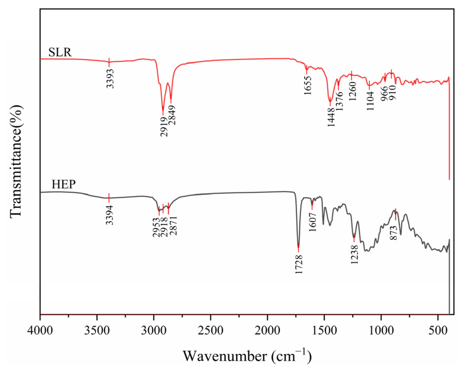
Figure 7 presents the FTIR spectra of HEP and SLR. For HEP, the broad peak at 3394 cm−1 is assigned to –OH stretching vibration. The triplet near 2900 cm−1 corresponds to saturated C–H stretching vibration. The absorption peak at 1728 cm−1 corresponds to C=O stretching vibration, confirming the successful introduction of butyl acrylate. The absorption peak at 1607 cm−1 arises from the C=C skeletal vibration of the benzene ring, indicating the retention of the bisphenol A epoxy structure. The peak at 1238 cm−1 is attributed to C–O stretching vibration, and the absorption peaks in the 850–950 cm−1 region are characteristic of epoxy groups. These results demonstrate that acrylate and epoxy resin are chemically bonded, forming a hybrid structure. The abundant active groups (e.g., hydroxyl, ether, and epoxy) can chemically interact with functional groups on various substrate surfaces, thereby imparting excellent adhesion to the coating [29].
For SLR, the broad peak at 3300–3400 cm−1 is assigned to the –OH stretching vibration. The peak at 1104 cm−1 is attributed to the C–O–C ether bond stretching vibration, confirming the presence of hydroxyl and ether bond structures in the system. The double peaks at 2919 cm−1 and 2849 cm−1 correspond to the asymmetric and symmetric stretching vibrations of saturated C–H, respectively. The double peaks at 1448 cm−1 and 1376 cm−1 correspond to C–H bending vibrations, confirming the existence of aliphatic hydrocarbon chains in asphalt. The C=C stretching vibration peak at 1655 cm−1 and the C–Cl stretching vibration peaks in the 750–550 cm−1 range indicate the introduction of chloroprene latex (containing unsaturated double bonds and chlorine atoms). The peaks at 966 cm−1 and 910 cm−1 correspond to the out-of-plane bending vibrations of =C–H, related to unsaturated structures in asphalt or modifiers. Collectively, these features confirm that SLR is a modified asphalt system composed of asphalt, chloroprene latex, and other modifiers. Asphalt serves as the matrix, providing good adhesion, flexibility, and waterproofing, while the chloroprene latex imparts excellent elasticity and aging resistance, improves asphalt-aggregate adhesion, reduces high-temperature flow and low-temperature cracking, and optimizes rheological properties and workability [23].

3.3. Morphological Analysis

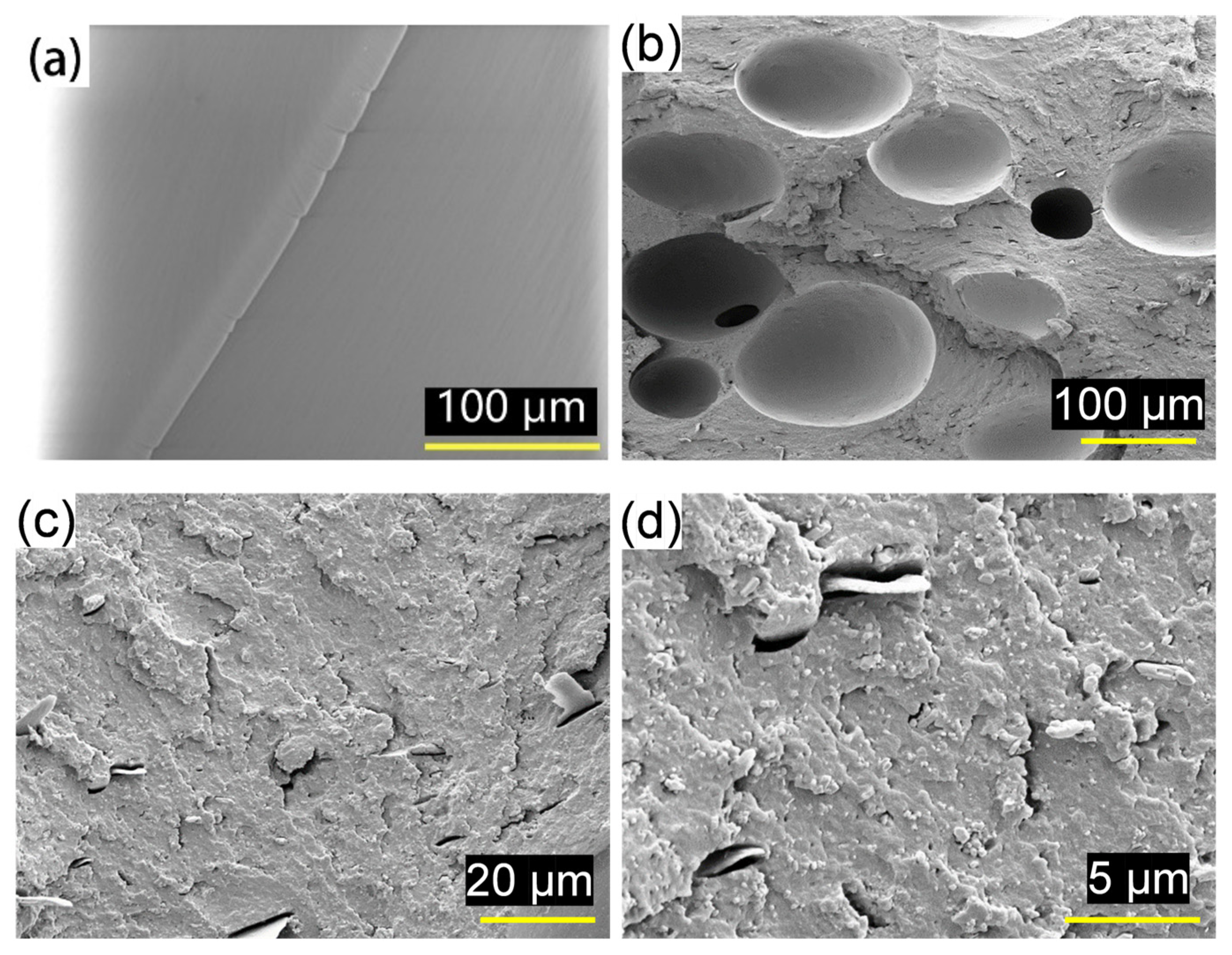
Figure 8 shows the tensile fracture morphologies of unmodified epoxy resin [21] and the HEP-modified epoxy resin. As shown in Figure 8a, the fracture surface of unmodified epoxy is smooth and flat, with no plastic deformation zone, exhibiting typical brittle fracture characteristics. River-line patterns are visible, aligning with the main crack propagation direction; the pattern density is low with no obvious branching, and local microcracks are present. These features indicate that cracks propagate rapidly and unstably along the weak interfaces of the crosslinked network without significant blunting or deflection. In contrast, the HEP fracture surface (Figure 8b,c, at 200× and 1000× magnifications) is rough, displaying river patterns and radiating crack propagation features, still indicating brittle fracture as the dominant mode [30]. However, small voids and tear ridges are locally visible, suggesting a certain degree of plastic deformation capacity. At 3000× magnification (Figure 8d), nanoscale voids distributed on the fracture surface and surrounding plastic deformation zones are observed. These voids result from debonding between the second-phase particles (acrylate) and the epoxy matrix in the hybrid system [31,32]. Collectively, these morphological features demonstrate that acrylate modification introduces a flexible deformation mechanism while preserving the rigidity of epoxy.
This mechanism dissipates fracture energy through interfacial debonding and localized plastic deformation, thereby inhibiting rapid crack propagation and significantly enhancing the abrasion resistance of the coating [33,34]. Under sand-laden water erosion, the HEP coating initially undergoes slight elastic deformation on its surface. Subsequently, debonding at the acrylate–epoxy interface occurs, generating small voids or shear bands [35]. These interfacial debonding and plastic deformation processes convert part of the impact energy that would otherwise be transmitted into the coating interior into thermal and interfacial energy, substantially reducing the stress intensity at the crack tip [36]. Furthermore, the incorporation of acrylate components increases the fracture toughness of the coating, enabling more effective resistance to surface damage and material loss under continuous friction and wear [37]. Additionally, the acrylate groups impart good hydrophobicity and chemical stability, which synergistically interact with the epoxy matrix to form a dense protective film against corrosive media [38]. Consequently, the HEP coating exhibits not only excellent abrasion resistance but also good adhesion and chemical corrosion resistance.

3.4. Dynamic Mechanical Property Analysis

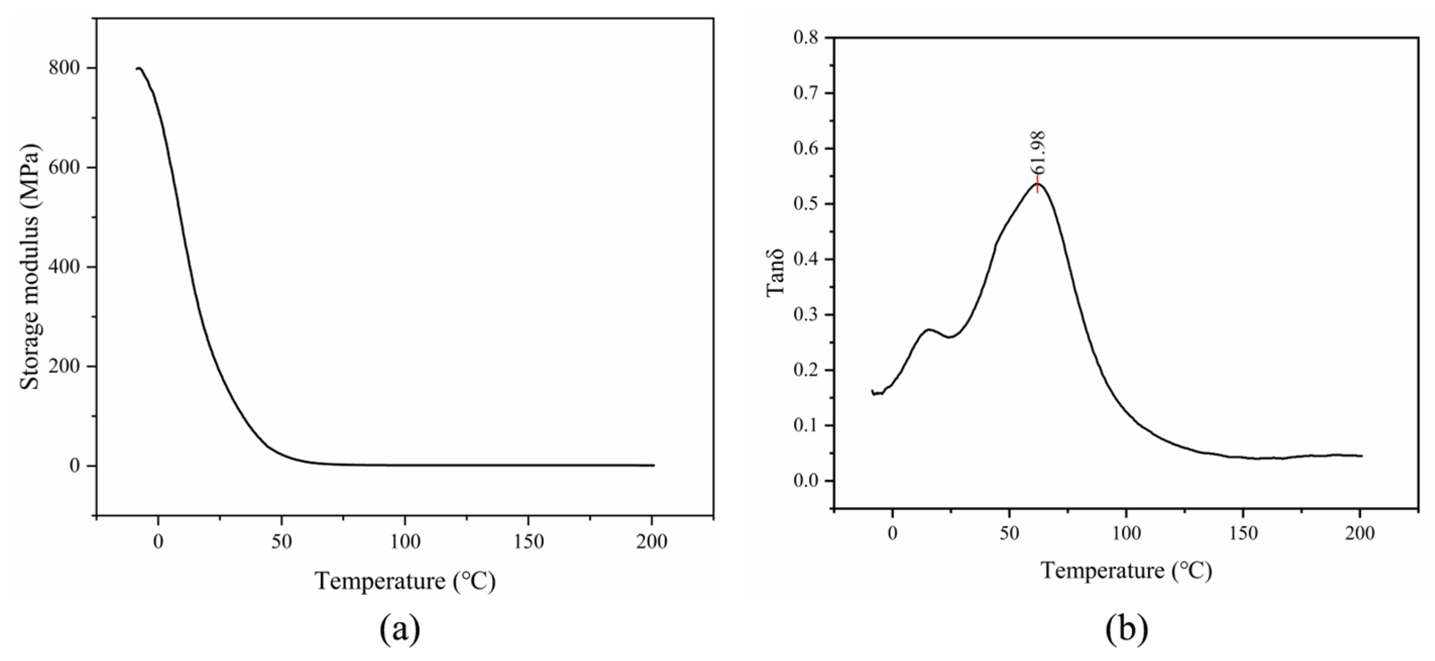
Dynamic mechanical analysis (DMA) is a common method for determining the glass transition temperature (Tg). The storage modulus (E’) reflects the material’s resistance to elastic deformation (i.e., stiffness), and the loss factor (tanδ) serves as a direct quantitative indicator of energy dissipation capacity: a higher tanδ value indicates greater efficiency in converting mechanical energy into heat [39]. Figure 9 presents the temperature dependence of E’ and tanδ for the HEP coating. As shown in Figure 9a, HEP exhibits a storage modulus (E’) exceeding 800 MPa at low temperatures, reflecting its rigid crosslinked network. Upon heating, the modulus gradually decreases and then drops sharply in the 50–70 °C range, corresponding to the primary glass transition of the epoxy-rich phase. In this temperature window, increased segmental mobility triggers the characteristic transition from the glassy to the rubbery state. At 25 °C, the E’ values of HEP and SLR are 190 MPa and 2.5 MPa, respectively, differing by approximately two orders of magnitude, indicating that HEP possesses a much higher resistance to deformation. Consequently, at ambient temperature, HEP behaves as a rigid glassy solid with excellent stiffness and structural stability. In Figure 9b, the tanδ peak of HEP corresponds to a Tg of 61.98 °C, which is significantly higher than the typical service temperature range of hydraulic concrete (25–40 °C). Therefore, under service conditions, HEP remains in the glassy state and can provide a wear-resistant substrate for the coating. In addition, a weak shoulder peak near 16 °C is attributed to the microphase separation of soft segments introduced by the acrylic–epoxy hybrid modification, which imparts a certain degree of toughness to HEP and prevents the brittle cracking observed in neat epoxy resins.
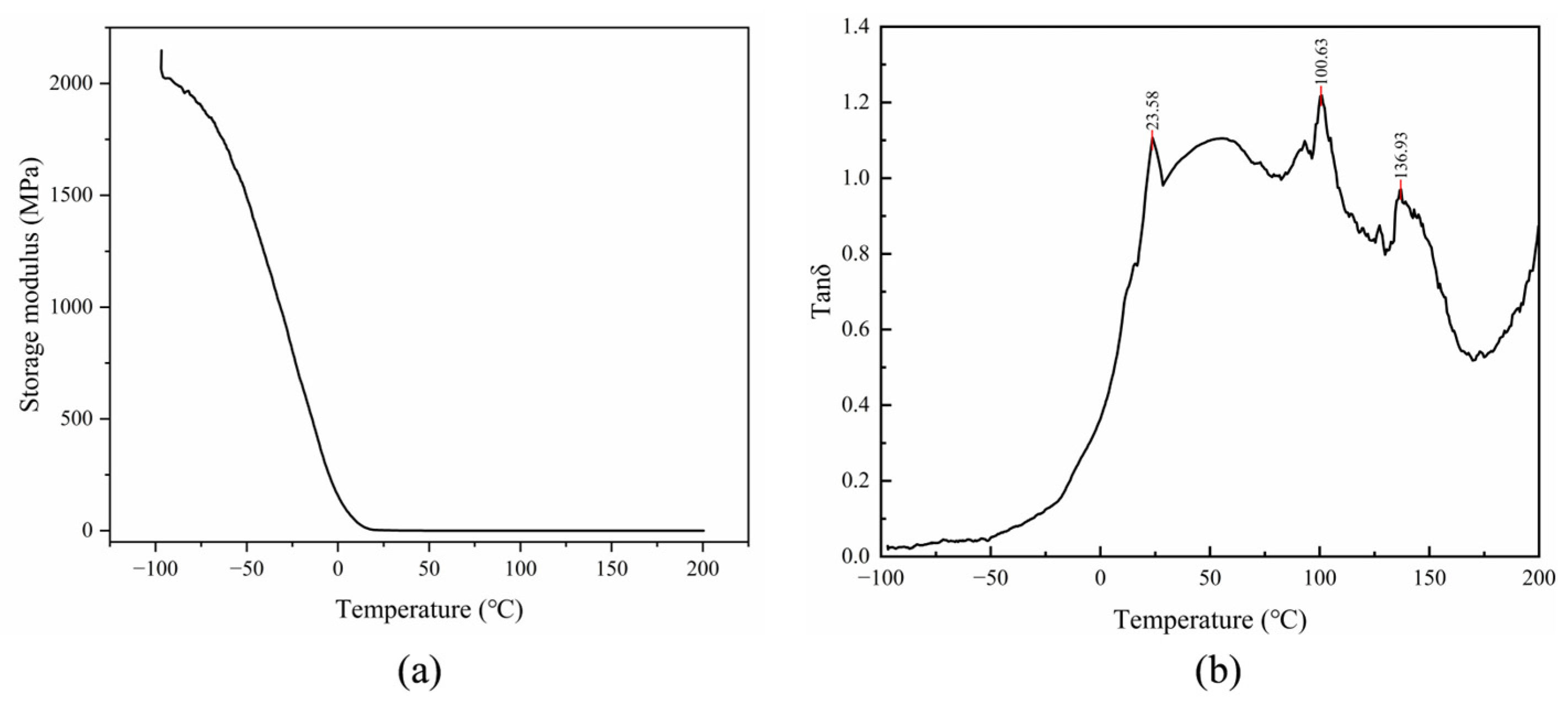
Figure 10 shows the DMA curves of the SLR intermediate layer. As seen in Figure 10a, the E’ of SLR stays above 1500 MPa in the range of −100 °C to −50 °C (glassy state), then decreases rapidly with increasing temperature and eventually remains relatively stable above 25 °C. This rubber-dominated viscoelastic response indicates that SLR is in the rubbery state at room temperature, where its crosslinked network enables stable reversible deformation, thereby rendering the modulus less sensitive to temperature variations. The SLR system exhibits multiple glass transition characteristics: the tanδ peak at 23.58 °C corresponds to the transition of the chloroprene latex main chain from the glassy to the rubbery state. This temperature is close to room temperature, indicating that SLR is in the rubbery state under normal service conditions, possessing high elasticity and large deformation capacity (elongation at break > 1000%), which meets the buffering and energy-absorbing requirements of the intermediate layer. The secondary peak at approximately 101 °C originates from the motion of asphalt molecular chains, and the high-temperature peak at 136.93 °C is attributed to the high-temperature relaxation of the asphalt-chloroprene latex crosslinked network [40]. This relaxation ensures that SLR retains adequate mechanical strength even at elevated summer temperatures (60–80 °C) on the surface of hydraulic structures, avoiding the creep failure typical of pure rubber materials. The presence of multiple Tg values confirms that SLR is a multiphase composite system consisting of a rubber phase, an asphalt phase, and an interfacial crosslinked network phase.
In terms of energy dissipation, HEP exhibits only one major tanδ peak near 61.98 °C with a peak value of 0.54 and a narrow full width at half maximum, indicating a homogeneous crosslinked structure dominated by a rigid epoxy phase. At room temperature, the tanδ of HEP is only about 0.26, reflecting low energy dissipation efficiency; it primarily withstands abrasion loads through its high storage modulus, demonstrating a “rigid load-bearing” characteristic. In contrast, SLR shows a much higher tanδ peak of 1.22 (at 100.63 °C), approximately 2.3 times that of the HEP main peak. At room temperature (25 °C), the tanδ of SLR is about 1.09, representing a 316% improvement in energy dissipation capacity over HEP, enabling rapid dissipation of impact energy from sediment-laden water flow.
The multiple glass transition temperatures (Tg) of SLR (at 23.58, 100.63, and 136.93 °C) establish a hierarchical energy dissipation network that fully covers the service temperature range of hydraulic structures from −20 °C to 80 °C. In contrast to HEP, which only enables effective energy dissipation near its single dominant Tg, the multi-Tg feature of SLR affords continuous energy absorption across low, ambient, and elevated temperatures. The gradient formed by the high Tg of HEP (61.98 °C) and the low Tg of SLR (23.58 °C) corresponds well with the modulus gradient of the “rigid top layer–flexible interlayer” structural design, giving rise to a synergistic “surface load-bearing and interlayer energy dissipation” mechanism. Under operational conditions, the HEP top layer maintains a glassy state, which enables effective resistance to mechanical cutting and abrasive erosion induced by sand-carrying water flow, consequently leading to a pronounced reduction in the wear rate of the underlying concrete substrate. Concurrently, SLR exists in a highly elastic rubbery state at room temperature, absorbing impact energy through large-scale deformation and dissipating over 90% of mechanical impact energy via its high tanδ value, which prevents energy transmission to the concrete matrix and inhibits the nucleation and propagation of fatigue cracks induced by abrasion. The gradient synergy between HEP and SLR overcomes the bottleneck of traditional single-layer epoxy coatings, which are “rigid but insufficiently tough.” It retains the excellent impact-abrasion resistance of HEP while incorporating the superior energy absorption capacity of SLR, thereby significantly enhancing the overall impact-abrasion resistance of the material.

3.5. Freeze–Thaw Durability Analysis

In cold regions, freeze–thaw cycling is one of the predominant factors responsible for the degradation of concrete structures. The damage mechanism originates from the volumetric expansion (approximately 9%) of pore water in concrete upon freezing at low temperatures, which generates crystallization pressure. Concurrently, unfrozen pore water migrates toward the colder zone, inducing osmotic pressure. The superposition of these two pressures leads to pore wall cracking and microstructural degradation, manifested as surface scaling, cracking, loss of mechanical properties, and increased porosity [41]. Permeability test results indicate that uncoated concrete specimens showed no water seepage even when the pressure was increased to 1.2 MPa, corresponding to a permeability rating of S12 (or P12), which fully meets the requirement of ≥P8 for hydraulic concrete specified in SL 677-2014 “Specification for hydraulic concrete construction” [42]. In contrast, under the same test conditions, the coated concrete specimens exhibited a significantly higher permeability rating of 2.0 MPa, demonstrating excellent impermeability.
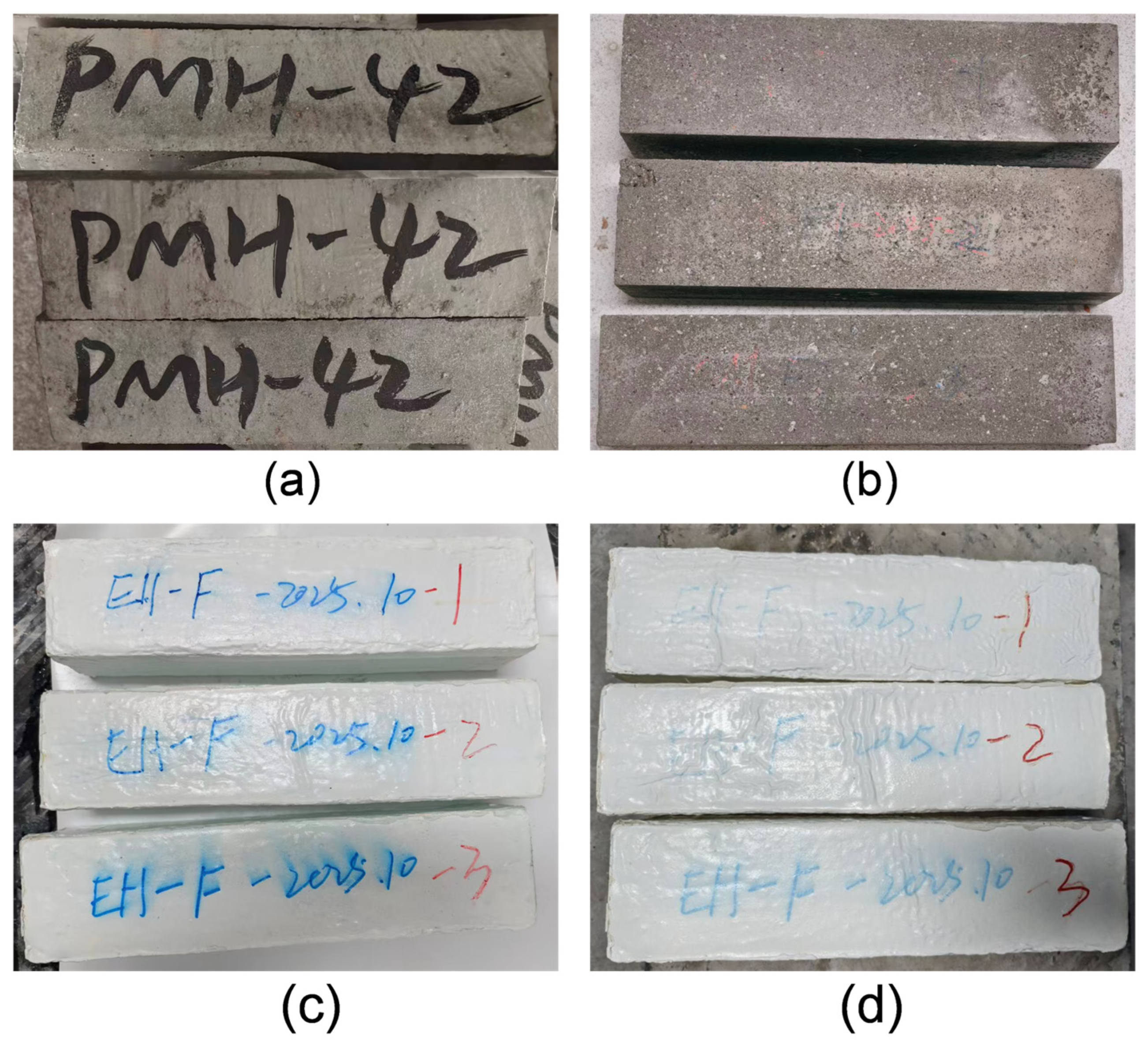
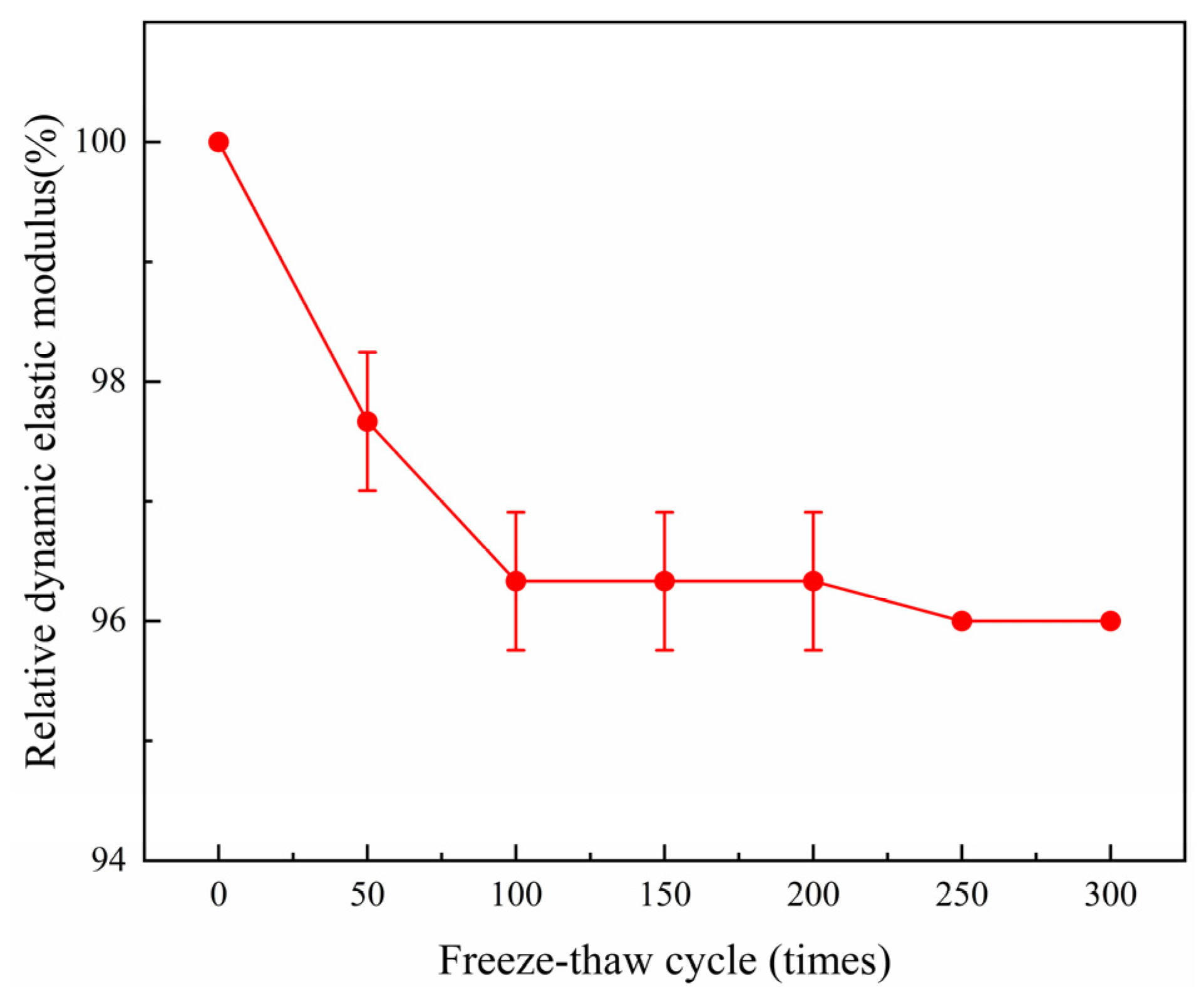
Figure 11 shows the surface morphologies of the uncoated concrete and the HIR-coated concrete before and after 300 freeze–thaw cycles. After 300 cycles, the uncoated concrete surface exhibited spalling and microcracks, whereas the coated concrete specimens showed very low mass loss and no visible surface deterioration such as peeling or pitting. As presented in Table 5 and Figure 12, the relative dynamic elastic modulus of the plain concrete fell below 60% after 250 freeze–thaw cycles. By contrast, although the relative dynamic elastic modulus of the coated specimens declines progressively with an increasing number of freeze–thaw cycles, it still maintains a value above 95% even after 300 cycles, which demonstrates that the composite coating system efficiently restrains the propagation of freeze–thaw damage in concrete. During freeze–thaw cycling, the dense HEP top layer acts as an effective barrier against water penetration into the concrete substrate. Even if a small amount of water ingress or local defects occur, the highly flexible SLR intermediate layer can buffer and absorb the internal stresses generated by ice crystal formation and temperature fluctuations, thereby preventing brittle cracking or delamination of the coating. Lu et al. [43] reviewed various protective coatings for hydraulic structures and reported that conventional epoxy coatings often suffer from microcracking under prolonged freeze–thaw exposure due to their inherent brittleness. The HIR system overcomes this limitation through the flexible SLR interlayer, which accommodates volume changes during freeze–thaw cycles and prevents crack propagation from the concrete substrate to the coating surface. These results indicate that the HIR coating system effectively suppresses freeze–thaw damage progression and maintains structural integrity under harsh cold-region conditions.

3.6. Analysis of Abrasion Resistance

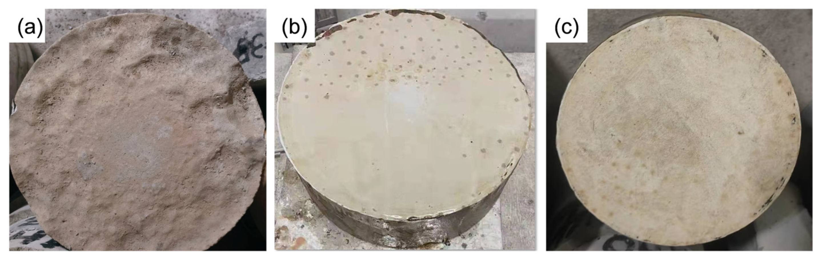
Figure 13 presents the experimental results of accelerated abrasion tests for three specimen groups: uncoated concrete, traditional epoxy resin-coated concrete, and HIR-coated concrete. Following the abrasion test, the uncoated concrete substrate exhibited substantial surface spalling, severe abrasive degradation, and morphological irregularity, accompanied by a wear rate of 1.8% and an anti-abrasion strength of 16.96 h/(kg/m2). In contrast, all coated concrete specimens maintained structurally integral surfaces with only negligible superficial defects. Specifically, the traditional epoxy resin-coated concrete had a wear rate of 0.3% and an anti-abrasion strength of 101.74 h/(kg/m2); the HIR-coated concrete had an extremely low wear rate of 0.1%, along with drastically suppressed mass loss relative to the uncoated specimens. The calculated anti-abrasion strength reached 254.35 h/(kg/m2), which was 15 times that of uncoated specimens and 2.5 times that of the traditional epoxy resin-coated specimens. Omranian et al. [8] investigated the abrasion behavior of various fiber-reinforced concretes for hydraulic structures and reported wear rates ranging from 0.5% to 1.2%. The HIR-coated concrete achieved an extremely low wear rate of 0.1%, representing a substantial improvement over fiber-reinforced concrete approaches. This comparison clearly demonstrates that the gradient multilayer design is more effective in enhancing impact-abrasion resistance than single-layer coatings or fiber reinforcement strategies. These results unambiguously demonstrate the outstanding abrasion resistance of the proposed HIR gradient composite coating system.
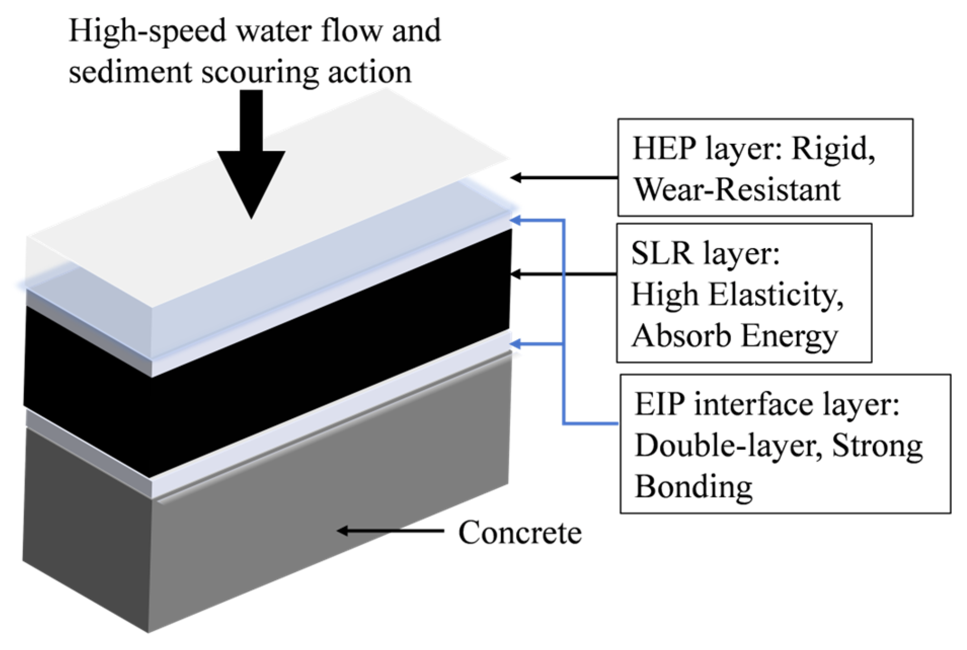
The outstanding abrasion resistance of the HIR composite coating system is attributed to the favorable interfacial compatibility and synergistic coupling between its constituent layers, as illustrated in Figure 14. The rubber phase in the SLR middle layer provides a toughening and energy-buffering effect. Its high elasticity endows the coating with excellent deformability. Under high-velocity water flow impact, the SLR layer dissipates impact energy through large-scale viscoelastic deformation, thereby suppressing the initiation and propagation of internal microcracks. Moreover, its superior elastic recovery behavior mitigates the accumulation of surface abrasive damage and reduces the long-term mass loss rate under repeated impact-abrasion conditions. The epoxy phase in the HEP top layer offers efficient rigidity and wear resistance. The HEP layer features a three-dimensional crosslinked hybrid network composed of rigid epoxy segments and flexible acrylic chains, achieving a desirable combination of stiffness and toughness. This tailored structure effectively resists mechanical stress from continuous impact and friction, preventing typical failure modes such as surface tearing and interfacial peeling. Through the rational design of this multilayer composite architecture and the synergistic functional cooperation of each layer, the HIR coating system achieves superior and durable impact-abrasion resistance.

4. Conclusions

This work innovatively developed a functionally graded multilayer composite protective coating system, designated HIR, for hydraulic concrete (strength grade C40) in cold regions. The HIR system consisted of a modified epoxy-based interfacial prime (EIP), a sprayed liquid rubber (SLR) middle layer, and a hybrid acrylic–epoxy resin (HEP) top layer, achieving an adhesion interfacial bonding strength with concrete substrates exceeding 2.0 MPa. The HEP surface layer has an elongation at break exceeding 30%, and the SLR intermediate layer achieves an elongation at break of over 1000%. This combination enables effective adaptation to deformation caused by water flow impact and wear, thereby inhibiting cracking and spalling. FTIR and DMA analyses revealed the hybrid structure of the HEP top layer and the multiple glass transition behaviors of the HIR system, enabling efficient energy dissipation across a wide temperature range. This represents an intrinsic toughening and impact-abrasion resistance mechanism distinct from conventional single-layer coatings. Benefiting from the synergistic effect of the dense water-blocking HEP layer and the highly flexible energy-absorbing SLR layer, the coated concrete maintains a relative dynamic elastic modulus above 95% after 300 freeze–thaw cycles, significantly suppressing internal structural deterioration. Furthermore, the synergistic coupling of the rubbery toughening phase and the rigid wear-resistant phase reduced the wear rate to 0.1% and increased the impact abrasion resistance to 254.35 h/(kg/m2)—values 15 times higher than that of uncoated concrete and 2.5 times higher than that of traditional epoxy resin-coated concrete—far exceeding the performance of traditional protective materials for hydraulic concrete.
This gradient composite design overcame the performance limitations of conventional epoxy materials in balancing flexibility, freeze–thaw resistance, and impact–abrasion resistance, thereby enriching the design theory of durable protective materials for harsh hydraulic environments. To further advance the engineering application and theoretical development of this composite coating system, future research should focus on long-term field exposure tests, full life-cycle assessments of economic and environmental benefits, investigations of substrate adaptability across different cement-based materials, and numerical simulations of coating failure mechanisms under complex service conditions.

Author Contributions

Investigation, W.H. and Y.C.; Data curation, Y.C., W.H., Q.L., D.C., X.C. and J.Z.; Writing—original draft, Y.C.; Writing—review and editing, W.H., X.C. and J.Z. All authors have read and agreed to the published version of the manuscript.

Funding

This research was funded by the Technical Consulting and Service Project of Mid-Route Source of South-to-North Water Transfer Co., Ltd.: “Experimental Study on a Novel High-Weather-Resistance Hybrid Polymer Abrasion-Resistant Material”, grant number ZSY/YG-SJ(2024)004 and Basic Research Funds for Central Level Public Welfare Research Institutes, grant number CKSF2026368/CL. Technical.

Data Availability Statement

The data presented in this study are available on request from the corresponding author.

Acknowledgments

The authors wish to acknowledge the assistance of the State Laboratory of Silicate Building Materials, Wuhan University of Technology, and the Institute of Materials and Structures, Changjiang River Scientific Research Institute, with the scanning electron microscope, universal testing machines, and other equipment.

Conflicts of Interest

Authors Quanhong Li and Dongdong Cui were employed by Mid-Route Source of South-to-North Water Transfer Co., Ltd. Authors Wei Han and Xizheng Chang were employed by the Material and Engineering Structure Department, Changjiang River Scientific Research Institute. The remaining authors declare that the research was conducted in the absence of any commercial or financial relationships that could be construed as a potential conflict of interest.

Abbreviations

The following abbreviations are used in this manuscript:
HIRHybrid epoxy–interfacial primer–rubber
HEPHybrid acrylic–epoxy resin
EIPModified epoxy-based interfacial primer
SLRSprayed liquid rubber

References

  1. Boutamart, M.; Rafqah, S.; Hadri, A.; Nouneh, K.; Zaidi, S.; Bichara, H.; Briche, S. Design of fluorine-free superhydrophobic coating for fibred architectonic concrete. Constr. Build. Mater. 2024, 425, 136086. [Google Scholar] [CrossRef] [Scilit]
  2. Liu, Q.; Andersen, L.V.; Zhang, M.; Wu, M. Abrasion damage of concrete for hydraulic structures and mitigation measures: A comprehensive review. Constr. Build. Mater. 2024, 422, 135754. [Google Scholar] [CrossRef] [Scilit]
  3. Guo, J.; Gao, M.; Wang, K.; Zhang, P. Mechanisms and influential variables on the abrasion resistance hydraulic concrete. Nanotechnol. Rev. 2022, 11, 2997–3019. [Google Scholar] [CrossRef] [Scilit]
  4. Sreedhar, B.K.; Albert, S.K.; Pandit, A.B. Cavitation damage: Theory and measurements—A review. Wear 2017, 372–373, 177–196. [Google Scholar] [CrossRef] [Scilit]
  5. Qiu, X.; Zhao, J.; Li, Z. Abrasion resistant characteristics of UHPC based on high-speed underwater method: Efficiency, process, evaluation, and mechanisms. J. Mater. Res. Technol. 2025, 34, 233–248. [Google Scholar] [CrossRef] [Scilit]
  6. Su, F.; Ma, X.; Lin, Y.; He, T. Exploring the factors influencing the abrasion resistance of hydraulic concrete based on underwater steel ball test. Case Stud. Constr. Mater. 2024, 20, e03020. [Google Scholar] [CrossRef] [Scilit]
  7. Liu, Q.; Li, L.; Andersen, L.V.; Wu, M. Studying the abrasion damage of concrete for hydraulic structures under various flow conditions. Cem. Concr. Compos. 2023, 135, 104849. [Google Scholar] [CrossRef] [Scilit]
  8. Omranian, S.A.; Eftekhar, M.R. A comprehensive study on the abrasion behavior of different types of fiber reinforced concrete in hydraulic structures. Constr. Build. Mater. 2024, 426, 135991. [Google Scholar] [CrossRef] [Scilit]
  9. Wu, F.; Chen, X.; Chen, J. Abrasion resistance enhancement of concrete using surface treatment methods. Tribol. Int. 2023, 179, 108180. [Google Scholar] [CrossRef] [Scilit]
  10. Du, H.; Shen, Y.; Zhang, W.; Kong, X.; Fu, Y. Fabrication of superhydrophobic concrete with stable mechanical properties and self-cleaning properties. J. Build. Eng. 2023, 67, 105950. [Google Scholar] [CrossRef] [Scilit]
  11. Gu, W.; Liu, R.; Zhang, Y.; Yu, X.; Feng, P.; Ran, Q.; Zhang, Y.; Zhang, Y. Robust water-borne multi-layered superhydrophobic coating on concrete with ultra-low permeability. Constr. Build. Mater. 2024, 411, 134573. [Google Scholar] [CrossRef] [Scilit]
  12. Jin, F.L.; Li, X.; Park, S.J. Synthesis and application of epoxy resins: A review. J. Ind. Eng. Chem. 2015, 29, 1–11. [Google Scholar] [CrossRef] [Scilit]
  13. Ajir, K.; Toufigh, V.; Ghaemian, M. Protecting ordinary cement concrete against acidic and alkaline attacks utilizing epoxy resin coating. Constr. Build. Mater. 2025, 472, 141003. [Google Scholar] [CrossRef] [Scilit]
  14. Guo, H.; Du, C.; Chen, Y.; Li, D.; Hu, W.; Lv, X. Study on protective performance of impact-resistant polyurea and its coated concrete under impact loading. Constr. Build. Mater. 2022, 340, 127749. [Google Scholar] [CrossRef] [Scilit]
  15. Dural, S.; Camadanlı, S.Ş.; Kayaman Apohan, N. Improving the mechanical, thermal and surface properties of polyaspartic ester bio-based polyurea coatings by incorporating silica and titania. Mater. Today Commun. 2024, 38, 107654. [Google Scholar] [CrossRef] [Scilit]
  16. Wang, L.; Wang, Y.; Zhang, J.; Wang, F.; Liu, Z.; Jiang, J. Investigation on self-healing polyurethane coating doped with lignin composites for protecting cementitious materials. Constr. Build. Mater. 2024, 411, 134368. [Google Scholar] [CrossRef] [Scilit]
  17. Özgümüş, S.; İyim, T.B.; Acar, I.; Küçükoğlu, E. Synthesis of novel silicone modified acrylic resins and their film properties. Polym. Adv. Technol. 2007, 18, 213–219. [Google Scholar] [CrossRef] [Scilit]
  18. Kumar, S.; Krishnan, S.; Mohanty, S.; Nayak, S.K. Synthesis and characterization of petroleum and biobased epoxy resins: A review. Polym. Int. 2018, 67, 815–839. [Google Scholar] [CrossRef] [Scilit]
  19. Jiang, Y.; Li, J.; Li, D.; Ma, Y.; Zhou, S.; Wang, Y.; Zhang, D. Bio-based hyperbranched epoxy resins: Synthesis and recycling. Chem. Soc. Rev. 2024, 53, 624–655. [Google Scholar] [CrossRef] [Scilit]
  20. Singh, S.K.; Singh, D.; Kumar, A.; Jain, A. An analysis of mechanical and viscoelastic behaviour of nano-SiO2 dispersed epoxy composites. Silicon 2020, 12, 2465–2477. [Google Scholar] [CrossRef] [Scilit]
  21. Ge, Z.; Zhang, W.; Huang, C.; Luo, Y. Study on epoxy resin toughened by epoxidized hydroxy-terminated polybutadiene. Materials 2018, 11, 932. [Google Scholar] [CrossRef] [Scilit]
  22. Xu, L.; Zhang, K.; Liu, Y. Hydraulic abrasion-resistant elastic epoxy resin materials. Adv. Mater. Sci. Eng. 2019, 2019, 9358139. [Google Scholar] [CrossRef] [Scilit]
  23. Wang, M.; Li, R.; Wen, Y.; Pei, J.; Xing, X.; Chen, Z. Rheological and aging behaviors of liquid rubber modified asphalt binders. Constr. Build. Mater. 2019, 227, 116719. [Google Scholar] [CrossRef] [Scilit]
  24. Ren, T.; Wan, C.; Song, P.; Xinyan, Y.; Wang, S. Efficient degradation of vulcanized natural rubber into liquid rubber by catalytic oxidation. Polym. Degrad. Stab. 2024, 225, 110822. [Google Scholar] [CrossRef] [Scilit]
  25. GB/T 16777-2008; Test Methods for Building Waterproofing Coatings. Standards Press of China: Beijing, China, 2008.
  26. SL/T 352-2020; Test Code for Hydraulic Concrete. China Water & Power Press: Beijing, China, 2020.
  27. GB/T 50082-2024; Standard for Test Methods of Long-Term Performance and Durability of Concrete. China Architecture Publishing & Media Co., Ltd.: Beijing, China, 2024.
  28. DL/T 5150-2017; Test Code for Hydraulic Concrete. China Electric Power Press: Beijing, China, 2017.
  29. Wei, H.; Xia, J.; Zhou, W.; Zhou, L.; Hussain, G.; Li, Q.; Ostrikov, K. Adhesion and cohesion of epoxy-based industrial composite coatings. Compos. Part B Eng. 2020, 193, 108035. [Google Scholar] [CrossRef] [Scilit]
  30. Kim, H.J.; Yoon, M.; Seo, B.; Lim, C. Effects of fatty acid modified epoxy resin on long-chain epoxy and its physical properties. J. Polym. Sci. 2023, 61, 2194–2202. [Google Scholar] [CrossRef] [Scilit]
  31. Ramos, V.D.; da Costa, H.M.; Soares, V.L.P.; Nascimento, R.S. Modification of epoxy resin: A comparison of different types of elastomer. Polym. Test. 2005, 24, 387–394. [Google Scholar] [CrossRef] [Scilit]
  32. Niu, C.; Du, K.; Xu, Z.; Li, Z.; Li, T.; Wang, R. Mechanical properties of epoxy resin composites modified by epoxy styrene-butadiene latex. J. Appl. Polym. Sci. 2023, 140, e54002. [Google Scholar] [CrossRef] [Scilit]
  33. Li, N.; Huang, J.; Wang, Y.; Xiao, L.; Fu, P.; Yu, H.; Nie, X.; Jiang, J.; Zhu, Y.; Guo, Z. Simultaneously strengthening, toughening, and conductivity improving for epoxy at ultralow carbonaceous filler content by constructing 3D nanostructures and sacrificial bonds. Compos. Part A Appl. Sci. Manuf. 2020, 137, 106014. [Google Scholar] [CrossRef] [Scilit]
  34. Xu, H.; Kong, L.; Zhang, Y.; He, Z.; Ran, L. Preparation and characterization of polyurethane composite modified epoxy resin for novel colored anti-skid pavement materials. Mater. Lett. 2024, 369, 136760. [Google Scholar] [CrossRef] [Scilit]
  35. Zhang, H.; Yang, D.; Chen, L.; Zheng, Y.; Zheng, H.; Cui, Y.; Wu, R. Fluorinated silicone-modified epoxy acrylate amphiphobic coatings exhibiting highly efficient resistance to simulants of chemical warfare agents. Eur. Polym. J. 2025, 228, 113793. [Google Scholar]
  36. Shi, T.; Zhang, Y.; Zhang, X.; Wang, Y.; Zheng, K. A strength based thermo-mechanical coupled cohesive zone model for simulating heat flux induced interface debonding. Compos. Sci. Technol. 2023, 243, 110255. [Google Scholar] [CrossRef] [Scilit]
  37. Ren, Y.; Zhang, L.; Xie, G.; Li, Z.; Chen, H.; Gong, H.; Xu, W.; Guo, D.; Luo, J. A review on tribology of polymer composite coatings. Friction 2021, 9, 429–470. [Google Scholar] [CrossRef] [Scilit]
  38. Zhou, Y.; Chen, G.; Yan, S.; Ni, C.; Yu, L.; Li, X. Epoxy composite coating with excellent anticorrosion and self-healing properties based on acrylate copolymers. Prog. Org. Coat. 2022, 172, 107098. [Google Scholar] [CrossRef] [Scilit]
  39. Zhang, K.; Huang, J.; Wang, Y.; Li, W.; Nie, X. Eco-friendly epoxy-terminated polyurethane-modified epoxy resin with efficient enhancement in toughness. Polymers 2023, 15, 2803. [Google Scholar] [CrossRef] [Scilit] [PubMed]
  40. Barcikowski, M.; Krolikowski, W.; Lenart, S. Microstructures of unsaturated polyester resins modified with reactive liquid rubbers. Polimery 2017, 62, 650–657. [Google Scholar] [CrossRef] [Scilit]
  41. Zhu, X.; Bai, Y.; Chen, X.; Tian, Z.; Ning, Y. Evaluation and prediction on abrasion resistance of hydraulic concrete after exposure to different freeze-thaw cycles. Constr. Build. Mater. 2022, 316, 126055. [Google Scholar] [CrossRef] [Scilit]
  42. SL 677-2014; Specification for Hydraulic Concrete Construction. China Water & Power Press: Beijing, China, 2014.
  43. Cong, L.; Wang, Y.; Gao, X. Enhancing the salt frost durability of concrete with modified epoxy composite coating. Materials 2025, 18, 737. [Google Scholar] [CrossRef] [Scilit]
Figure 1. Photographs of the raw materials: (a) cement, (b) fly ash, (c) sand, and (d) crushed granite.
Buildings 16 01799 g001
Figure 2. Preparation process of the coated specimen: (a) grinding; (b) application of interface agent; (c) spraying of SLR; (d) spraying of HEP.
Buildings 16 01799 g002
Figure 3. Concrete specimens (a) and coated concrete specimens (b) after 300 freeze–thaw cycles.
Buildings 16 01799 g003
Figure 4. Concrete specimen (a) and coated concrete specimen (b) after abrasion resistance test.
Buildings 16 01799 g004
Figure 5. Adhesion performance of SLR and HIR on concrete: (a) failure patterns; (b) adhesion strength results.
Buildings 16 01799 g005
Figure 6. Tensile mechanical properties of HEP (a) and SLR (b).
Buildings 16 01799 g006
Figure 7. FTIR Spectra of HEP and SLR.
Buildings 16 01799 g007
Figure 8. Micrographs of the tensile fracture surfaces of pure epoxy resin (a) (Adapted from [21]) and HEP modified epoxy resins (bd).
Buildings 16 01799 g008
Figure 9. Storage modulus (a) and loss tangent (tanδ) curves (b) of HEP.
Buildings 16 01799 g009
Figure 10. Storage modulus (a) and loss tangent (tanδ) curves (b) of SLR.
Buildings 16 01799 g010
Figure 11. Surface morphologies of concrete and coating concrete specimens before and after 300 freeze–thaw cycles: (a) concrete specimen before cycling; (b) concrete specimen after cycling; (c) coating concrete specimen before cycling; (d) coating concrete specimen after cycling.
Buildings 16 01799 g011
Figure 12. Trends of relative dynamic modulus in freeze–thaw tests.
Buildings 16 01799 g012
Figure 13. Comparison of surface morphologies of different concrete specimens after the abrasion test: (a) uncoated concrete specimen; (b) traditional epoxy resin-coated concrete specimen; (c) HIR-coated concrete specimen.
Buildings 16 01799 g013
Figure 14. Analysis diagram of the abrasion resistance mechanism of HIR-coated concrete.
Buildings 16 01799 g014
Table 1. Mixture proportion of concrete.
Water-Cement RatioConcrete Material Consumption (kg/m3)Water-Reducing Agent (%)Air-Entraining Agent (%)
WaterCementFly AshSandCoarse Aggregate
0.391122883251714710.70.01
Table 2. Main chemical composition of cement.
Chemical CompositionSiO2Fe2O3Al2O3CaOMgONa2OK2OLoss on Ignition
Content (%)20.704.416.1664.001.820.201.201.51
Table 3. Main chemical composition of fly ash.
Chemical CompositionSiO2Fe2O3Al2O3TiO2CaOSO3Loss on Ignition
Content (%)46.886.8130.891.062.460.620.68
Table 4. Main performance of coating.
PropertyHEPSLRHIR
Tensile strength (28 d, MPa)7.07 ± 0.540.79 ± 0.05
Elongation at break (28 d, %)36 ± 5.281152 ± 17.44
Adhesion strength to concrete (MPa)1.64 ± 0.182.14 ± 0.20
Glass transition temperature Tg (°C)6224, 101, 137multi-Tg features
Permeability resistance (MPa)≥2.0
Relative dynamic elastic modulus (after 300 freeze–thaw cycles, %)>95
Rate of mass loss (after 300 freeze–thaw cycles, %)0.14 ± 0.05
Wear rate (after abrasion test, %)0.12 ± 0.04
Anti-abrasion strength (h/(kg/m2))254.35 ± 27.05
Table 5. Relative dynamic modulus and mass loss rate of uncoated concrete and HIR-coated concrete under freeze–thaw cycles.
Freeze–Thaw CyclesSpecimen TypeRelative Dynamic Elastic Modulus (%)Mass Loss Rate (%)
0Uncoated concrete100.0 ± 0.00.00 ± 0.00
HIR-coated concrete100.0 ± 0.00.00 ± 0.00
50Uncoated concrete91.3 ± 0.50.10 ± 0.05
HIR-coated concrete97.5 ± 0.20.03 ± 0.03
100Uncoated concrete88.6 ± 0.90.29 ± 0.05
HIR-coated concrete96.6 ± 0.4−0.01 ± 0.04
150Uncoated concrete82.83 ± 5.20.36 ± 0.06
HIR-coated concrete96.5 ± 0.2−0.06 ± 0.03
200Uncoated concrete81.0 ± 5.30.41 ± 0.06
HIR-coated concrete96.3 ± 0.4−0.11 ± 0.03
250Uncoated concrete63.9 ± 11.00.46 ± 0.14
HIR-coated concrete96.2 ± 0.2−0.14 ± 0.04
300uncoated concrete– (Failure)– (Failure)
HIR-coated concrete95.7 ± 0.2−0.14 ± 0.05
Disclaimer/Publisher’s Note: The statements, opinions and data contained in all publications are solely those of the individual author(s) and contributor(s) and not of MDPI and/or the editor(s). MDPI and/or the editor(s) disclaim responsibility for any injury to people or property resulting from any ideas, methods, instructions or products referred to in the content.