Article

Large Language Model-Based Method for HVAC System Control Code Automatic Generation

1
Institute of Refrigeration and Cryogenics, Zhejiang University, Hangzhou 310013, China
2
Hangzhou Qiantang District Housing Security and Property Management Service Center, Hangzhou 310013, China
3
Zhejiang Province Institute of Architectural Design and Research, Hangzhou 310006, China
*
Author to whom correspondence should be addressed.
Buildings 2026, 16(9), 1722; https://doi.org/10.3390/buildings16091722
Submission received: 27 March 2026 / Revised: 22 April 2026 / Accepted: 24 April 2026 / Published: 27 April 2026

Abstract

The control code is an essential part of achieving energy-saving control in HVAC systems. Although there are existing methods for automatically generating control code, these methods still largely rely on expert knowledge for intervention. HVAC systems are highly personalized, with varying types of equipment, different quantities of equipment, and diverse data transmission protocols, all of which still require manual processing, resulting in low efficiency and a strong dependence on human input. To address this challenge, a method based on large language models is proposed. The basic idea is to leverage the understanding, reasoning, and coding capabilities of large language models, provide sufficient information to the model using the RAG (Retrieval-Augmented Generation) technique, and validate the accuracy of the code through a simulation model. By iterating repeatedly, the accuracy of the code is improved, ultimately enabling the automatic generation of control code. The evaluation used 173 laboratory rooms from an actual project to verify the efficiency and accuracy of this method. The results show that this method is highly efficient, processing a single room in just 5 min, and performs well under project-specific conditions, with a code generation accuracy of 97.1%.

1. Introduction

The energy consumption of buildings is one of the primary sectors of global energy consumption, with a significant energy footprint. Among the total energy consumption of buildings, Heating, Ventilation, and Air Conditioning (HVAC) systems account for 36%, ranking first [1,2]. In most cases, they have significant energy-saving potential [3,4]. Moreover, the energy saving rate was around 14% for heating, ventilation and air conditioning (HVAC) systems as reported in Ref. [5]. Precision control of HVAC (Heating, Ventilation, and Air Conditioning) systems has emerged as a pivotal factor in enhancing building energy efficiency. Under the dynamic conditions of both indoor and outdoor environments, it enables precise matching and optimization of operational parameters through real-time monitoring, intelligent analysis, and adaptive regulation. The essence of precision control lies in the construction of a multi-dimensional control loop, encompassing the meticulous regulation of key indicators such as temperature, humidity, air velocity, and air quality. The control of HVAC relies on control codes to execute predetermined logic for each system component [6], and the quality of control code directly impacts the effectiveness of control execution.
Traditionally, the control codes for HVAC systems have mainly been manually generated, crafted by engineers and domain experts based on experience and rules. This method is not only inefficient, consuming considerable time and human resources, but also struggles to guarantee accuracy under complex and variable working conditions. With the expansion of building scale and the increase in system complexity, while manually created control code can be verified repeatedly to ensure correctness, it often struggles to quickly adapt and optimize in the face of dynamically changing environmental conditions and diverse user needs, thereby limiting control precision and efficiency. With the development of technologies such as artificial intelligence and big data, automatic generation methods for control codes have emerged. Currently, there are mainly two types of methods for automatic control code generation: template and parameter-based methods [7,8] and Model-Based Design (MBD) methods [9,10,11].
Template and parameter-based methods generate code that meets specific requirements through pre-set code templates and parameters. Although this method can quickly generate code based on different parameters, the design of the templates themselves is a highly manual and experience-dependent process. In complex systems, designing templates that cover all potential needs and exceptions requires substantial time and human resources. Moreover, for HVAC scenarios, the requirements of each system differ, often necessitating the redesign of templates, which limits their application due to insufficient flexibility.
In the other category, MBD and automatic code generation, during the design phase, engineers create mathematical models to describe the behavior and logic of the system. These models act as “executable blueprints” that can be used to verify whether the system functions meet the requirements. Subsequently, automatic code generation tools are utilized to directly convert these models into production-level code that can run on actual hardware. This method elevates the level of design abstraction, allowing designers to focus more on system function description. However, the establishment of models and the design of control logic still require human intervention, especially when dealing with large-scale or highly customized scenarios; this process often requires significant time and expertise, resulting in higher costs.
The core challenge of automatic control code generation lies in the algorithm’s need to understand system structures based on existing cases, autonomously modify them for personalized systems, and convert them into structurally correct control code based on equipment interlock rules, safety rules, and other requirements. The key issue with the above methods is the weak generalization ability caused by rigid frameworks. In the HVAC field, scenes are numerous and complex, with each project having its unique design requirements, environmental conditions, and operating parameters. When encountering new scenarios or demands not covered by the templates, the existing templates are difficult to adapt and require manual modification and expansion. Therefore, it is necessary to develop new methods to address the aforementioned issues of insufficient template generalization, limited adaptability, and restricted scalability.
The rise of large language models (LLMs) has opened up new possibilities for the generation of control code in HVAC (Heating, Ventilation, and Air Conditioning) systems. These models, trained on vast amounts of data [12,13,14,15,16], possess robust capabilities in natural language understanding and generation [17,18], enabling them to handle complex contextual relationships and produce high-quality text or code. They not only comprehend human language but also extract information from structured or unstructured data, generating logically sound and syntactically correct code tailored to specific requirements. Additionally, large language models exhibit powerful reasoning abilities, allowing them to extract patterns from existing cases through analogical and inductive learning and apply these insights to new scenarios, thereby addressing issues of insufficient generalization. In the field of code generation, large language models have already demonstrated their potential. For instance, Tarassow utilized large language models to retrieve modular code documentation and generate comprehensive code [19], showcasing the model’s capabilities in code integration and optimization. Liu et al. employed large language models to adjust PID control parameters, achieving automatic optimization of control effects [20], which proves their practicality in control system optimization. Fu et al. further validated the performance of large language models in complex tasks by evaluating their code generation capabilities [21]. In the field of chemistry, large language models can autonomously design, plan, and execute complex experiments [22], demonstrating their logical reasoning and execution abilities in multi-step tasks. In mathematics and computer science, these models have found new solutions to long-standing problems (such as the cap set problem) and proposed optimization algorithms for challenges like the bin packing problem [23], highlighting their innovativeness in tackling complex issues. Additionally, large language models have made significant progress in fields such as biomedicine [24], materials science [25], and environmental science, proving their broad application potential in interdisciplinary research. These cross-domain applications demonstrate that LLMs possess both the reasoning ability to generalize from existing cases and the code generation capability required for HVAC control code automation. The combination of these two capabilities provides new approaches to addressing issues such as insufficient generalization, limited adaptability, and scalability in the generation of HVAC control code. With the guidance of a few cases, large language models can automatically generate control code that meets specific requirements, significantly improving development efficiency and accuracy.
This motivates the development of a more flexible and generalizable approach to HVAC control code generation, capable of handling diverse project configurations without relying on predefined templates or manual intervention. However, there are three unresolved critical issues in the application of large models for automatic control code generation:
(1)
HVAC systems involve various devices and data sources, such as a single room’s terminal system, which includes devices like air valves, water valves, frequency converters, temperature sensors, pressure sensors, etc., involving a dozen variables. Different devices process and transmit data in distinct ways, with a typical example being different data units leading to variations in data magnitude. The carriers of this information include text documents, images, tables, and more, which face the problem of vast amounts of information but limited effective information. How to integrate multifaceted information and efficiently convert it into the required control commands remains an insufficiently solved problem.
Retrieval-Augmented Generation (RAG) technology is a method that combines information retrieval with text generation [26]. In this technology, the model first extracts relevant information fragments from a large amount of data through a retrieval step, then combines these fragments with the model’s own language generation capabilities to produce text output. This approach is characterized by high accuracy and rich information content. In the computer field, RAG has been studied for retrieving abnormal log files [27]; in the field of coal mine information management, the introduction of RAG technology has increased the accuracy of GPT-4’s responses from 49.3% to 80.5% [28]; and in the field of education, RAG has been used to play the role of a teacher, retrieving correct answers with 100% accuracy in experiments [29]. Therefore, RAG technology has the potential to integrate multimodal data using large language models and convert it into standardized documents. Combined with large language models, RAG technology has been proven to accurately obtain data and has strong scalability [30,31].
(2)
Actual applications have high requirements for safety and reliability. AI-based control methods often face trust issues, which limit their application in engineering practice. AI control methods are typically data-driven, meaning they discover patterns through training on large amounts of data to achieve precise control. However, data-driven methods suffer from poor interpretability, with results based on statistics rather than logical reasoning. In control scenarios where logic is emphasized, the difficulty in explaining the process can lead to trust issues. Code generated by LLMs often exhibits considerable uncertainty and may sometimes fail to compile or meet specified requirements [32].
Particularly in actual control scenarios, safety is a vital aspect; control errors that lead to accidents can threaten the safety of personnel and equipment and cause significant financial losses. For example, a water flow control error in winter that causes a pipe to freeze and crack can ultimately lead to water leakage, which, at a minimum, disrupts production and, at worst, causes electrical accidents, threatening lives. Therefore, for control code, safety checks are indispensable.
Simulation refers to the full-factor reconstruction and digital mapping of the working status and progress of a physical entity in the information space [33]. It is an integrated multi-physics, multi-scale, ultra-realistic, dynamic probabilistic simulation model that can be used to simulate, diagnose, predict, and control the implementation process of physical entities in real environments, enabling prediction and verification in the virtual space without affecting real-world safety. In the aerospace field, simulations have been used to verify spacecraft performance, improving experimental accuracy by 15% [34], and in additive manufacturing, simulations have been applied to predict the effects of 3D printing, with an error of only 2.4% compared to actual experiments. Therefore, to meet the requirements for safety and reliability in practical applications, we will use automatically generated simulation models as a safety verification module to validate the safety of control codes. Experiments show that the safety check function integrated within the system can improve output safety [25], and simulation can verify the safety of control codes in a virtual environment [35,36,37] and provide a basis for modification, guiding large language models to revise the code.
(3)
The generation of control code for HVAC (Heating, Ventilation, and Air Conditioning) systems involves multiple complex and interrelated tasks, such as information integration, code generation, code verification, and modification. These tasks require different capabilities and processing logic. Although large language models excel in natural language processing and code generation, they were originally designed as general-purpose tools and lack a deep understanding of the complex requirements in specific domains [38]. For example, information integration requires extracting valid information from multi-source heterogeneous data, code generation must adhere to strict logic and rules, and code verification necessitates high-precision safety evaluation. These tasks not only require powerful generative capabilities but also demand in-depth domain knowledge, logical reasoning abilities, and rigorous safety control. When executed solely by large language models, they may fail to fully cover these requirements, potentially leading to incomplete, inaccurate, or impractical results that do not meet the demands of real-world applications.
A multi-agent framework is a distributed artificial intelligence system composed of multiple agents, each responsible for specific tasks and collaborating through communication to achieve complex goals. Within this framework, different agents can focus on tasks such as information integration, code generation, code verification, and modification, enabling modular processing of complex problems. The feasibility of multi-agent frameworks has been validated in various fields. In multimodal data processing tasks, the introduction of a multi-agent framework has yielded better results in tasks such as object detection and image understanding compared to baseline models, demonstrating the framework’s robust capability in handling heterogeneous data [39]. Additionally, the multi-agent framework has been applied in the Abstraction and Reasoning Corpus (ARC) Challenge, where multiple agents decomposed complex problems, achieving a 45% success rate on 111 test problems, significantly surpassing the current ARC world record of 30.5%. This further highlights the framework’s notable advantages in logical reasoning and task decomposition [40]. Introducing a multi-agent framework into the field of HVAC control code generation holds broad application prospects. Its modular design and collaborative mechanisms can effectively address the decomposition and integration of complex tasks, improving the efficiency and quality of code generation while meeting domain-specific safety and logical requirements.
To address these challenges, we have designed a framework based on large language models to assist in the writing and optimization of control code in the HVAC industry. Unlike classical automation engineering approaches such as template-based methods and Model-Based Design, which rely on predefined frameworks and require manual intervention when encountering scenarios outside their design scope, the proposed method leverages the reasoning and generalization capabilities of large language models to handle previously unseen configurations without human involvement. This fundamentally addresses the limitation of poor generalization in existing methods, enabling the system to autonomously adapt to diverse and personalized HVAC scenarios beyond the coverage of any fixed template or model.
The main contributions of this study are as follows:
By introducing RAG (Retrieval-Augmented Generation) technology, the efficient integration and standardization of multi-source heterogeneous information in the HVAC field were achieved. This addresses the issue of scattered and non-uniform information in real-world projects, providing a high-quality data foundation for control code generation.
By integrating simulation technology, a virtual verification environment was constructed to evaluate and validate the safety of automatically generated HVAC control code. This resolves the engineering risks caused by logical errors or safety hazards in traditional methods, ensuring the safety and reliability of control code in practical applications.
Through a multi-agent framework, the complex tasks involved in HVAC control code generation were decomposed into modular processes. Leveraging the reasoning and generation capabilities of large language models, this approach addresses the poor adaptability and scalability of traditional methods in complex scenarios, significantly improving the efficiency and flexibility of code generation.

2. Materials and Methods

2.1. Multi-Agent Framework Overview

2.1.1. Workflow Description

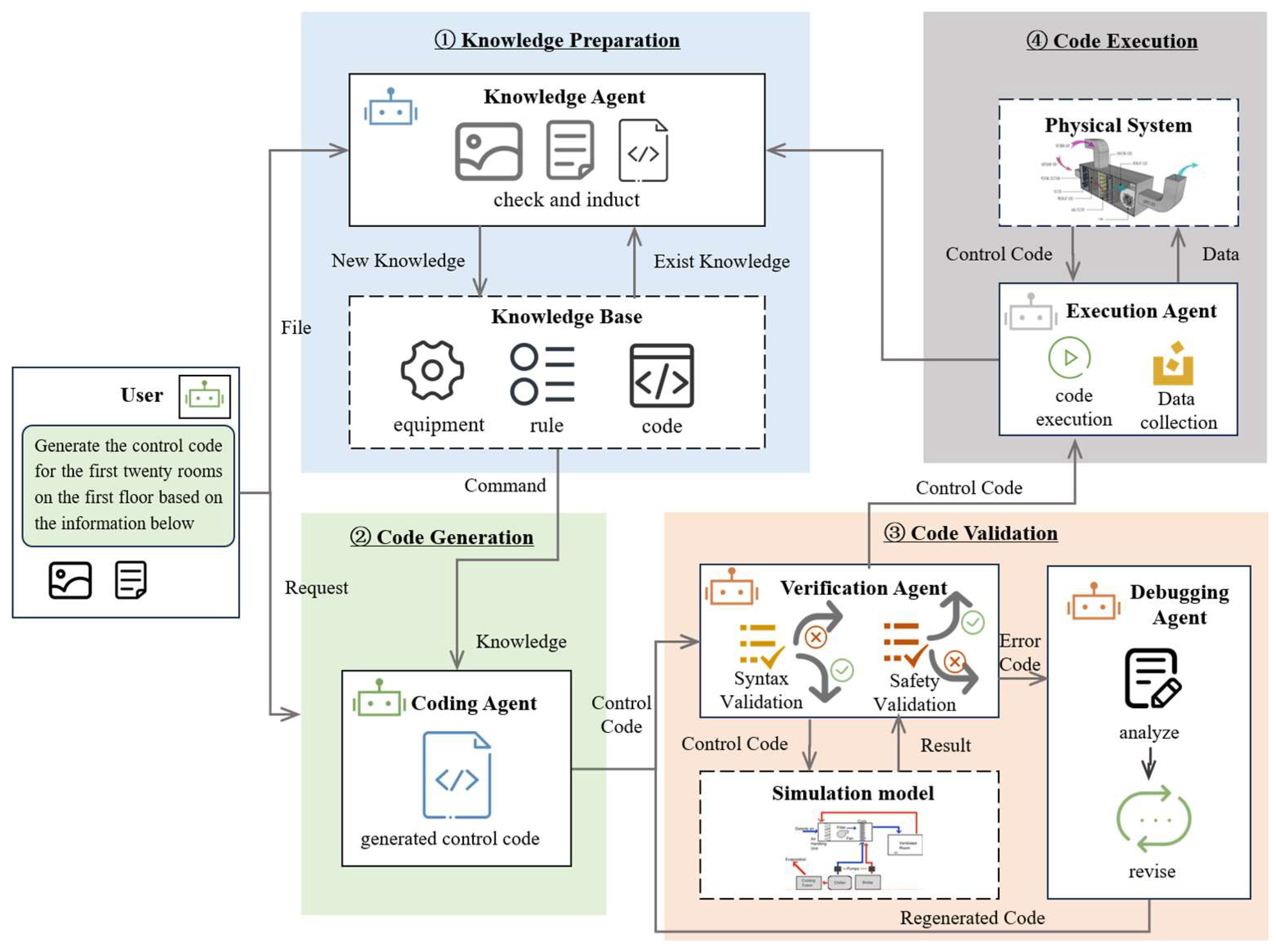
The framework takes multi-source heterogeneous data provided by users as input to accomplish the generation, iterative modification, and application of HVAC system control code. A multi-agent team based on LLM completes the task through four stages, as illustrated in Figure 1:
Knowledge Preparation: Extract knowledge from user-uploaded files and dynamically update the knowledge base through conflict detection and constraint validation.
Code Generation: A coding agent generates control code based on general and personalized knowledge.
Code Validation: Evaluates control code from multiple dimensions (syntax and safety). A debugging agent iteratively optimizes the code.
Code Execution: Deploys the verified code to the actual system and collects execution results to update the case knowledge base.

2.1.2. Agent Roles and Functions

The framework consists of five agents: Knowledge Agent, Coding Agent, Verification Agent, Debugging Agent, and Execution Agent.
Knowledge Agent: Responsible for processing multi-source heterogeneous data and dynamically updating the knowledge base. When new knowledge is detected, the agent identifies the file type, invokes the corresponding extraction module, and uses RAG technology to extract knowledge. It compares new knowledge with the existing base to ensure compliance with physical laws and industry standards before incorporation.
Coding Agent: Responsible for generating control code. The agent uses RAG technology to search for data transmission format rules, interlocking control rules, and other knowledge, and retrieves similar cases from the knowledge base using device similarity. Through the coding agent, the LLM’s understanding and coding capabilities are leveraged to learn from a small number of cases and enable experience transfer between different projects.
Verification Agent: Validates the control code based on the simulation model. The verification process includes: (1) Syntax Validation—executing the code in a controlled development environment to identify syntax errors or logical inconsistencies; (2) Safety Validation—simulating various operating scenarios (device startups/shutdowns, emergency shutdowns, abnormal conditions) to evaluate whether the control code meets safety requirements. If the code fails, the agent sends it with error feedback to the debugging agent.
Debugging Agent: Receives error information from the Verification Agent, classifies the errors, and generates a repair plan. It analyzes the code, generates a detailed error report including problem type, scenario, and modification suggestions, then uses semantic understanding and code generation capabilities to automatically correct and optimize the code. The optimized code is resubmitted to the Verification Agent.
Execution Agent: Receives the validated control code and deploys it to the corresponding controllers for real-world execution. It collects execution results and sends them to the Knowledge Base Agent for updating the knowledge base with new case data, providing data support for future case recommendations.

2.1.3. Support Components in Multi-Agent Framework

Knowledge Base: Constructed in two parts: generalized knowledge and personalized knowledge (Table 1). Generalized knowledge includes basic physical rules, industry standards, equipment control rules, coding rules, and demonstration cases. Personalized knowledge is built for each specific project, including device lists, device parameters, and data transmission formats. All knowledge is stored as dynamic arrays and can be updated by the knowledge agent. The knowledge base is constructed through a two-stage process. For generalized knowledge, ASHRAE Guideline 36 and other relevant industry standards serve as the primary sources. The documents are segmented and processed by an LLM to extract structured summaries, which are then reviewed and verified by domain experts before incorporation into the knowledge base. For personalized knowledge, project-specific documents such as equipment manuals and design specifications are directly processed by the LLM for automatic extraction and structuring.
Simulation Platform: Physical models of the system (e.g., EnergyPlus24.1.0, TRNSYS18) are developed on the simulation platform. Upon receiving control codes from the Verification Agent, the platform performs validation through real-time interaction with these physical models and returns test results.

2.2. Multi-Agent Collaboration Process

2.2.1. Preliminary Knowledge Preparation

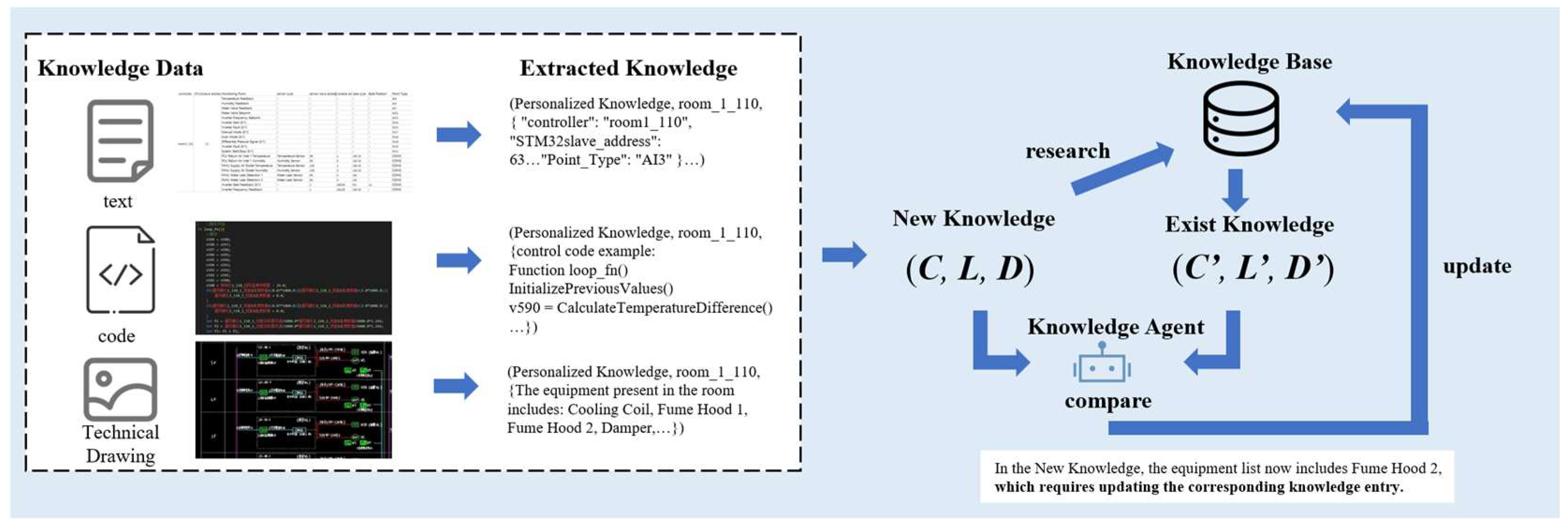
This stage emphasizes the integration and standardization of heterogeneous information sources. It extracts valid information from multi-source datasets by invoking specialized modules for knowledge parsing and representation, then employs LLM-driven semantic reasoning for conflict detection and constraint validation, ensuring the incorporated knowledge is both logically consistent and compliant with engineering standards, as illustrated in Figure 2.
During the knowledge validation phase, the knowledge agent utilizes a large language model (LLM) to perform conflict detection and constraint validation on newly uploaded knowledge. The specific technical approach is as follows:
Both new and existing knowledge are represented in structured markup. For example, existing knowledge can be represented as a triple (C, L, D), where C denotes the knowledge category (e.g., “personalized knowledge”), L denotes the location identifier (e.g., “Room 112”), and D denotes the device identifier (e.g., “device name, device type, interface type, slave address, data format.”). New knowledge k n e w and existing knowledge k e x i s t are represented as
k n e w = C n e w ,   L n e w ,   D n e w
k e x i s t = C e x i s t ,   L e x i s t ,   D e x i s t
To guide the large language model in conflict detection, a prompt function is constructed to convert the new and existing knowledge into natural language descriptions.
The prompt is input into the large language model, leveraging its semantic understanding capabilities for conflict detection and constraint validation. The large language model generates the judgment result through the following steps:
Conflict Detection: The model analyzes the relationship between the new and existing knowledge in terms of category, location, and device identifier. For example, if the category and device are the same but the locations differ (e.g., L n e w = Room 112, L e x i s t = Room 111), the model determines that there is no conflict.
Constraint Validation: The model further checks whether the new knowledge complies with existing knowledge. For example, whether the quantity and type of equipment are different.
The model’s output can be represented as
C o n f l i c t k n e w ,   k e x i s t = T r u e , i f   t h e   L L M   j u d g e s   t h a t   a   c o n f l i c t   e x i s t s F a l s e o t h e r w i s e
After validation, the new knowledge is written into the knowledge base in the form of a dynamic array, supporting efficient retrieval and real-time updates. This process exhaustively enumerates the files uploaded by users and the knowledge categories in the knowledge base to achieve a comprehensive summary of information. This significantly enhances the efficiency and accuracy of code generation by providing more precise information.

2.2.2. Code Generation

The code generation process is similar to the modeling process but more complex due to the more intricate structure of the code, which requires additional knowledge supplementation. This supplementation involves expert knowledge, device parameters, coding rules, and case-based hints. High-quality prompt engineering is used to improve the accuracy of code generation by large language models. It is worth noting that when personalized situations that require special processing by a large language model are emphasized, the large model will have better processing capabilities. Therefore, when constructing prompt structures, it is necessary to include descriptions of personalized situations.
Knowledge is stored as triples (C, L, D), where C denotes the knowledge category, L denotes the location identifier, and D denotes the device identifier. During the prompt construction process, knowledge with the same C and L is utilized to build personalized prompts for specific locations. Additionally, general knowledge relevant to the task type is selected as supplementary prompts.
The process of constructing personalized prompts is as follows:
Select triples from the knowledge base that share the same concept C and L domain as the current task:
S L =   { C i , L i , D i C i =   C , L i =   L }
Concatenate all descriptions Di in SL to form the personalized prompt:
P personal = concat D 1 , , D n   where C i , L i , D i S L
The selection of general knowledge is based on task type and device category, following these steps:
Calculate task description similarity: Before computing similarity scores, the key terms are defined as follows. The task feature T is determined by the initial user instruction. For example, if the user requests control code generation for the ventilation system of a specific room, T captures this intent as a natural language description. For each triple (Ci, Li, Di), the task similarity function in Equation (6) outputs 1 if the knowledge described in Di is relevant to the current task T, and 0 otherwise. For instance, if Di describes the sequential relationship between fan startup and air valve opening, it is considered relevant to a ventilation control task and outputs 1. Conversely, if Di describes the relationship between dry-bulb and wet-bulb temperature, it is unrelated to the task and outputs 0:
s i m t a s k D i ,   T = 1 i f   D i   i s   r e l e v a n t   t o   T 0 o t h e r w i s e
Calculate device category similarity: The device category E refers to a vector representation of the devices involved in the current task. Specifically, for a given task involving a set of device types, each dimension of the vector corresponds to a device type, and the value represents the quantity of that device in the task. For example, if the current task involves 3 air valves, 2 water valves, and 2 variable frequency drives, the corresponding task vector is E = (3, 2, 2). The operator Embed(Ei) maps the devices appearing in knowledge triple i into the same vector space. If knowledge i involves air valves and water valves but no variable frequency drives, its corresponding vector is Embed(Ei) = (1, 1, 0), with zero values for absent device types. For each triple (Ci, Li, Di), compute the similarity between its device category Ei and the current task’s device category E:
sim device E i , E = cos Embed E i , Embed E = Embed E i · Embed E ( | | Embed E i | |   ×   | |   Embed E | | )
where Embed E i · Embed E denotes the dot product and ||·|| denotes the L2 norm. This allows the device similarity between a knowledge entry and the current task to be quantified based on their shared device composition.
Compute comprehensive similarity: Combine the task description similarity and device category similarity using a weighted sum to obtain the comprehensive similarity:
sim total D i , T , E i , E = α sim task D i , T + 1 α sim device E i , E
Select the top five most relevant triples: Sort the triples in descending order based on the comprehensive similarity score and select the top five as supplementary prompts:
S top 5 = { C i , L i , D i C i , L i , D i S sorted 1 : 5 }
Construct the supplementary prompt: Concatenate the descriptions from to form the supplementary prompt:
P supplement = concat D 1 , D 2 , , D 5
The selection of the top five most relevant triples is based on the following rationale: since the demonstration case already provides the primary code framework and structural logic, the supplementary knowledge retrieved via similarity ranking serves as complementary information rather than the primary generation source. Its main purpose is to supply critical constraints and domain-specific rules to prevent the LLM from making significant errors in edge cases. In practice, five entries are sufficient to cover the majority of device-related issues encountered in typical HVAC scenarios, while avoiding excessive information redundancy that could interfere with the model’s generation process. It should be noted that this number is not fixed and can be adjusted according to the scale and complexity of the specific project.
Combine the personalized prompt and the supplementary prompt to build the final prompt:
P final = c o n c a t ( P personal , P supplement )
Once the Coding Agent completes the code, it is sent to the Verification Agent for validation.
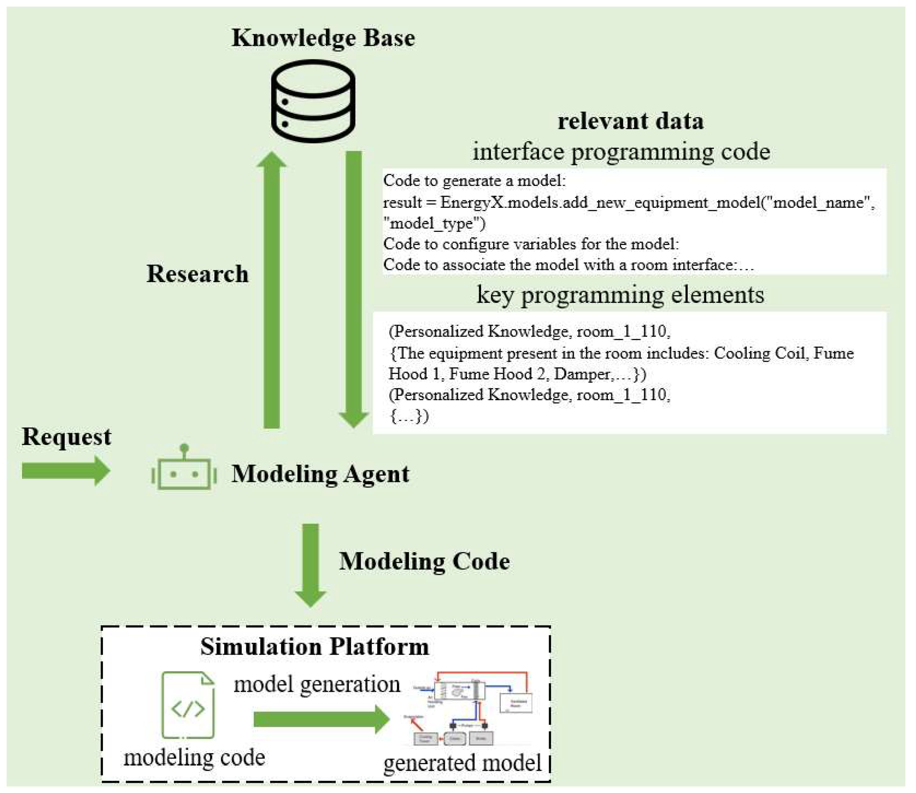
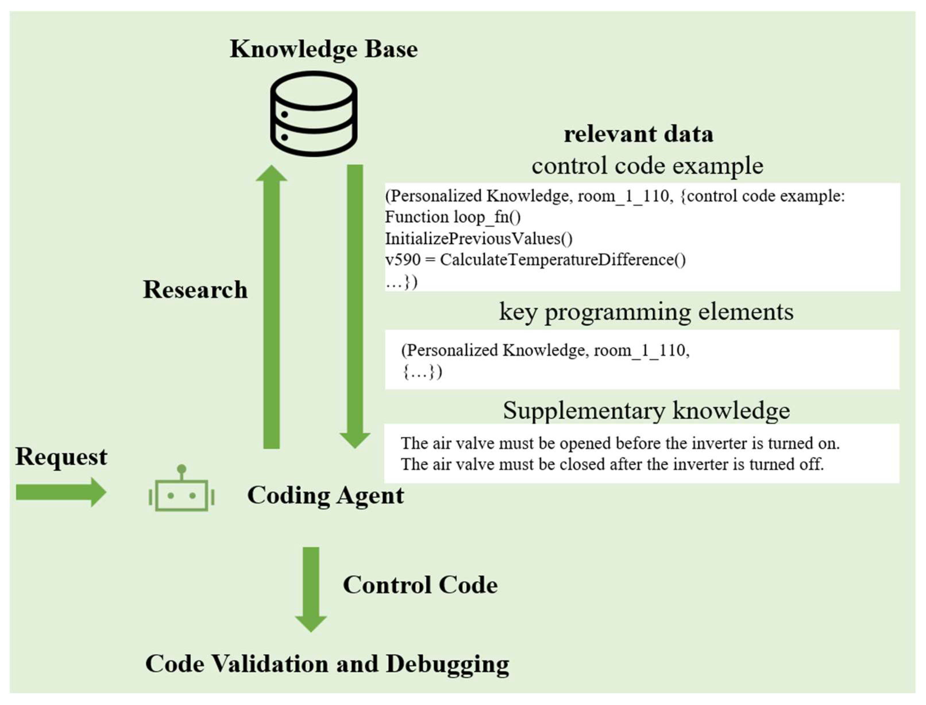
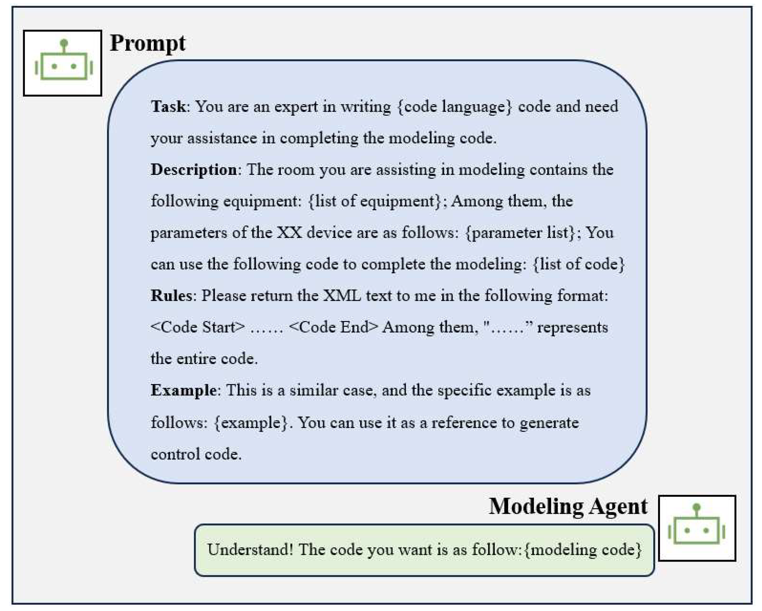
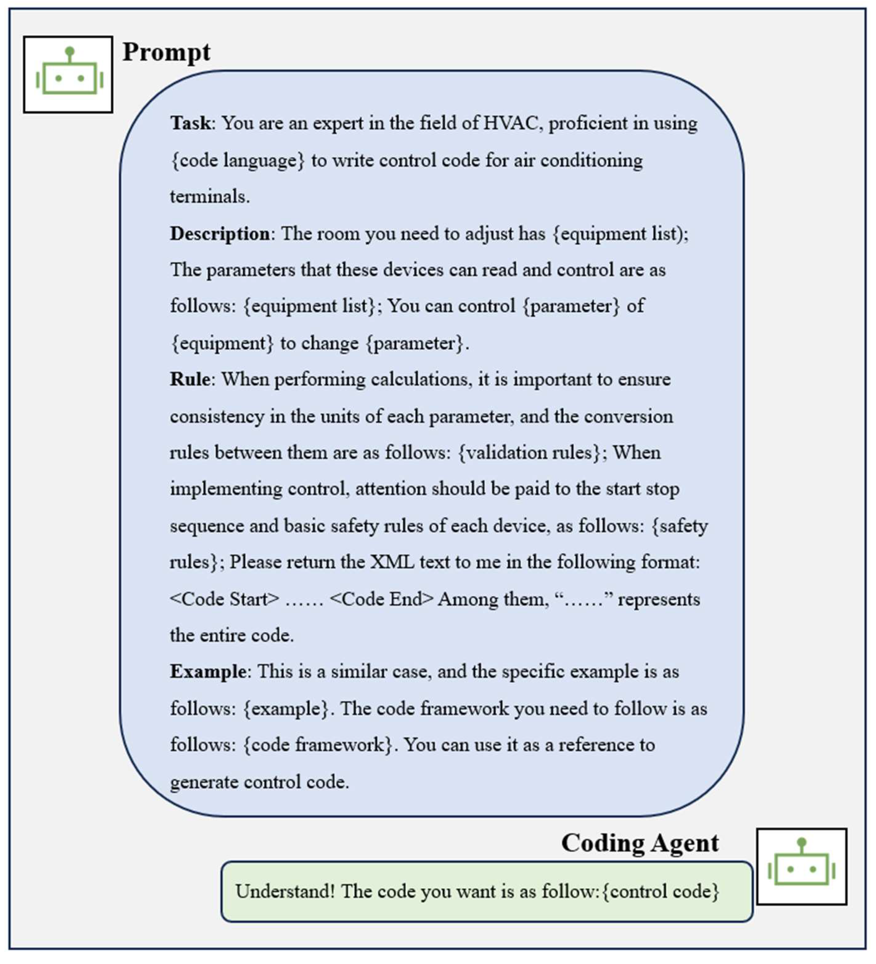
During the prompt construction process, the architecture can be designed to enable large language models to better comprehend the prompts. The example of the prompt is as follows, as illustrated in Figure 3, Figure 4, Figure 5 and Figure 6 and a specific example is provided in Appendix A.

2.2.3. Code Validation and Debugging

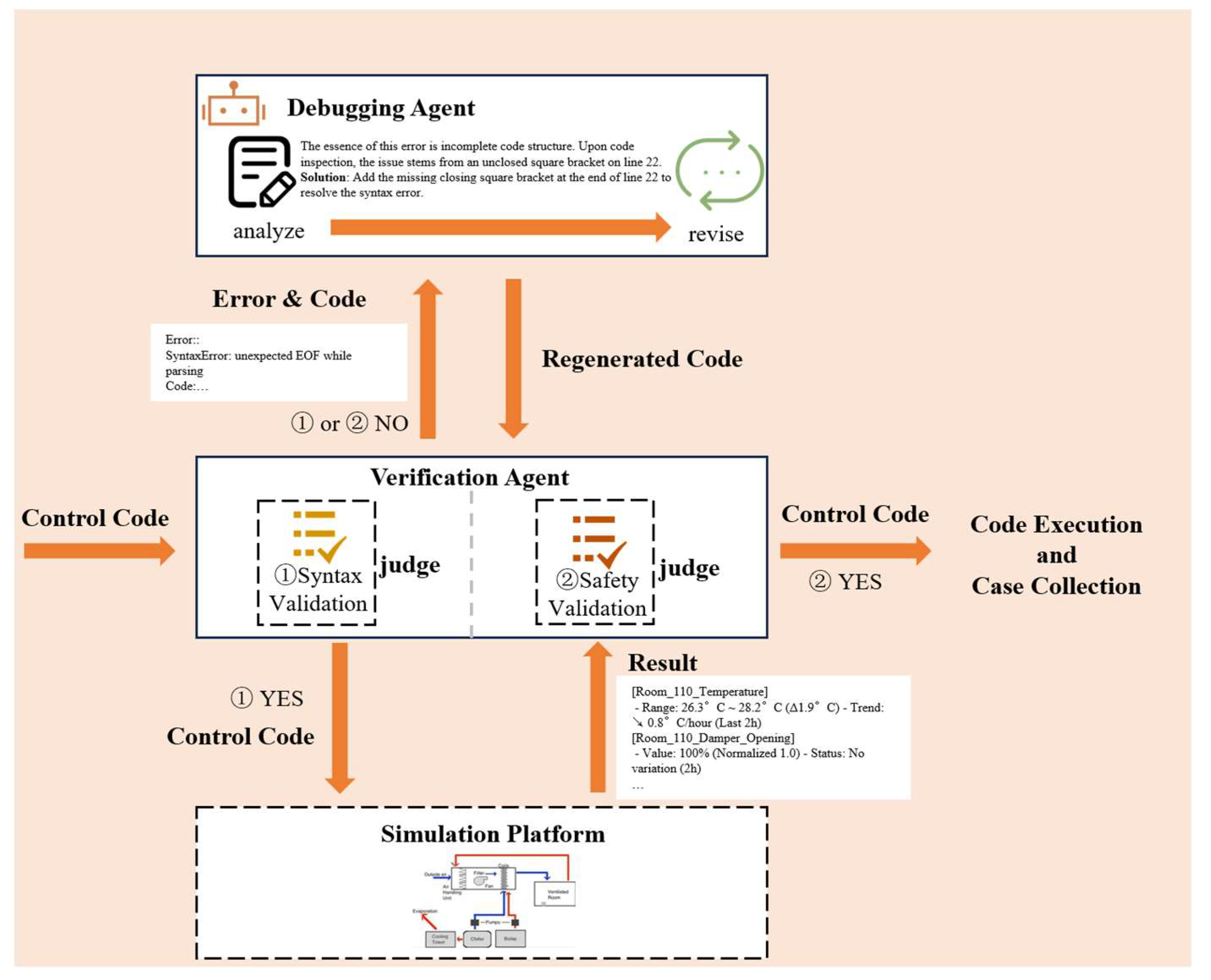
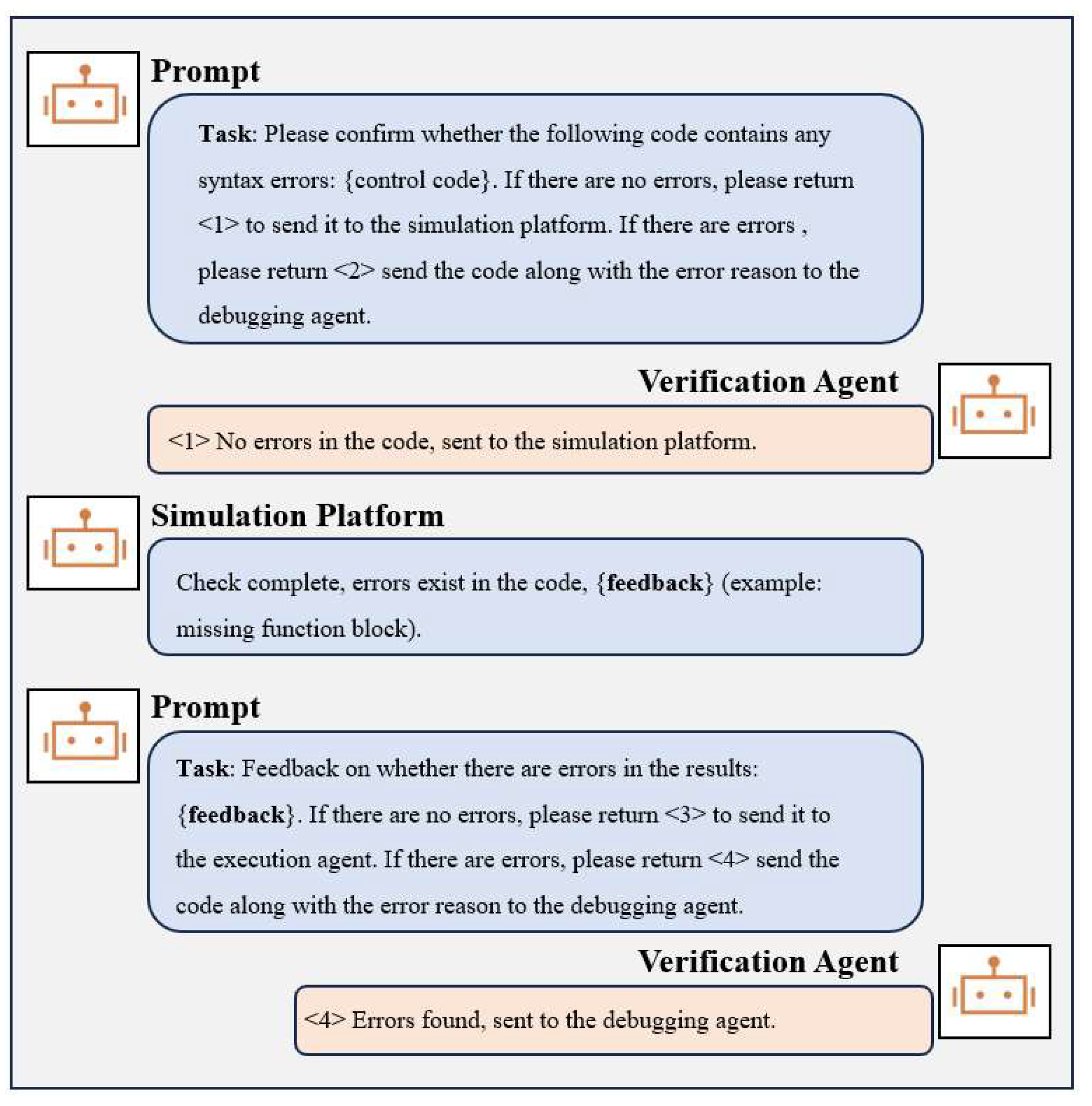
The Verification Agent receives the control code from the Coding Agent and validates it. As illustrated in Figure 7, initially, the Verification Agent calls the appropriate syntax validation module to detect any syntax errors in the control code, ensuring its technical correctness. Once the code passes the syntax check, it is input into the corresponding model on the simulation platform, where various operating scenarios, such as device startup/shutdown, emergency shutdown, and abnormal conditions, are simulated to evaluate the safety of the control code. This includes verifying the rationality of the startup/shutdown sequence, the effectiveness of interlock conditions, and whether any operational logic could lead to equipment damage or system failure. If the code passes the validation, it is sent to the Execution Agent. If it fails, the code and error information are sent to the Debugging Agent for correction.
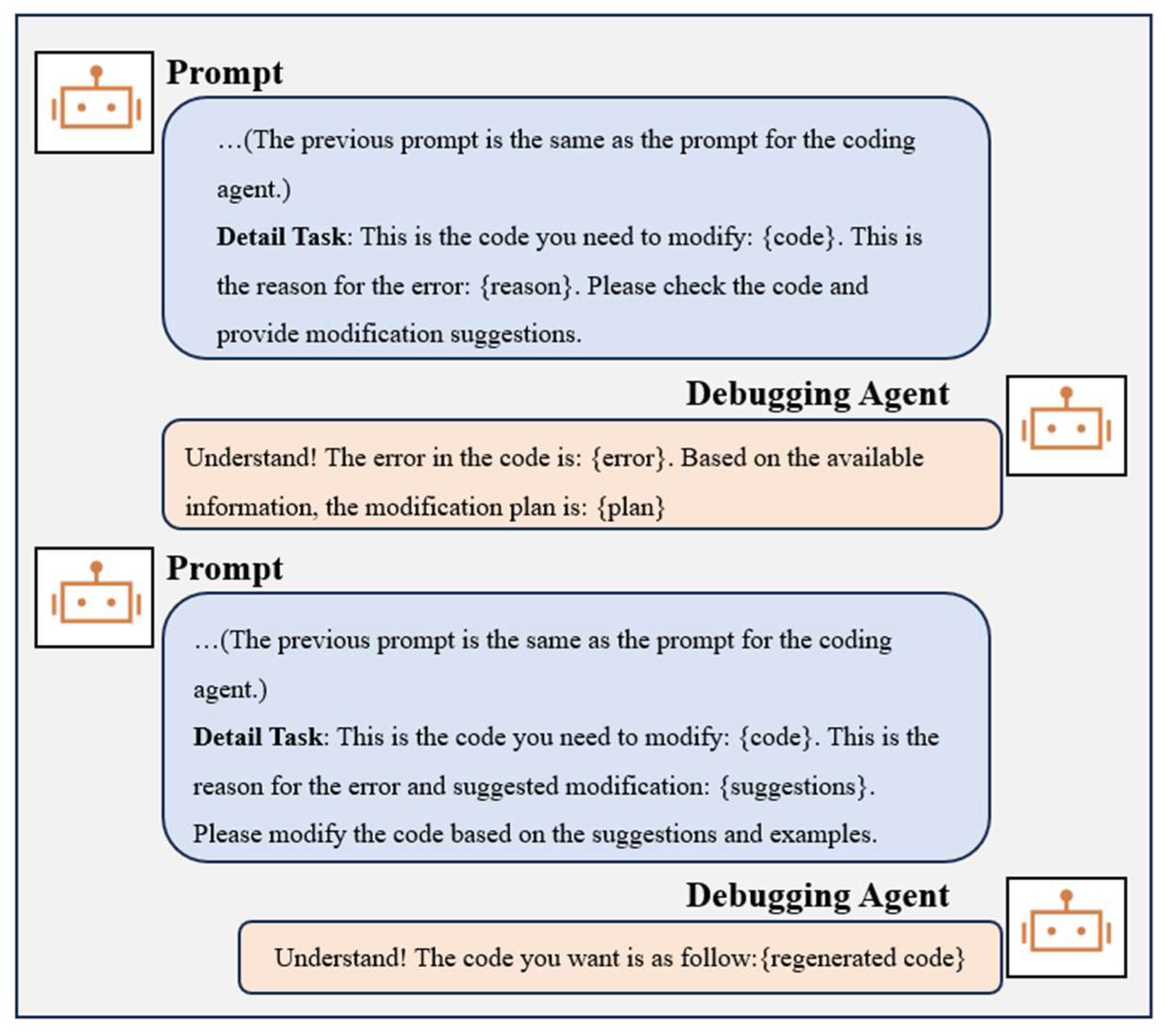
The Debugging Agent analyzes the received code and error report, classifies the errors, and generates a repair plan. For syntax errors, the Debugging Agent provides modification suggestions for the specific erroneous lines. For logical or safety errors, the Debugging Agent identifies potential risks and recommends optimizing the control process or modifying the operation sequence. Subsequently, the Debugging Agent uses its semantic understanding and code generation ability to correct and optimize the code. The optimized code is then resubmitted to the Verification Agent for further validation.
The verification and debugging process follows an iterative design, where each iteration targets improvements based on the results of the previous validation. Through multiple iterations, the safety, reliability, and performance of the control code are progressively enhanced until it meets deployment standards. The example of the prompt is as follows, as illustrated in Figure 8 and Figure 9.

2.2.4. Code Execution and Case Collection

The Execution Agent receives the validated control code and deploys it to the corresponding controllers for real-world execution. It collects actual execution results, annotates cases based on device types and quantities, and sends results to the Knowledge Base Agent for updating the case knowledge base. This step validates the practical applicability of the code and provides real-world project cases for future case recommendations.

3. Results

3.1. Experimental Design

We conducted experiments based on a real-world project. This project is a laboratory renovation, involving four buildings and 173 rooms. The controllable devices include fan variable frequency drives (VFD), water valves, and air valves. Controllable parameters include VFD startup/shutdown, VFD frequency settings, water valve opening settings, and air valve switches. Readable parameters include room temperature, supply air temperature, fume hood sash height, ventilation section airflow speed, current water valve opening, current VFD switch status, current VFD frequency, and current air valve switch status. The requirement is to maintain room temperature and pressure stability through the fresh air system, as the return air system is uncontrollable. PID control is required, and safety interlocking control must be implemented in case of low winter temperatures, with a switch to anti-freeze mode if the supply air temperature is too low. These parameters and control requirements are derived from an actual laboratory room used as the representative template in this study, reflecting the real-world controllable and readable variables as well as the operational requirements of the installed system. Each laboratory contains a varying number of fume hoods, which intermittently expel indoor air; some rooms have multiple sets of fresh air equipment, leading to data naming inconsistencies. Due to different fume hood models in each building, there are variations in data transmission units. In special cases, fume hoods may send erroneous data, which must be processed in the code based on data analysis. As illustrated in Table 2, the following are the impacts of personalization on the code:
To test the generalization capability, only one code example is provided for all 173 rooms. We selected DeepSeek-V3 as the core model and introduced GLM4-Air as a lightweight comparison model.

3.2. Evaluation Criteria

The evaluation focuses on four aspects: syntax correctness, functional completeness, control logic, and reliability.

3.2.1. Syntax Correctness (SC)

Syntax correctness is the foundation of code evaluation. If the code contains syntax errors, it will fail to compile or run correctly, thereby affecting the implementation and testing of subsequent functionalities. Therefore, assessing the syntax correctness of the code is a critical step in ensuring its executability. The syntax correctness score is calculated by Equation (12).
S C = N N S E N T × 100 %
where NNSE is the number of code groups with no syntax errors and NT is the total number of experimental groups.

3.2.2. Functional Completeness (FC)

Functional completeness evaluates whether the code implements all the required functionalities as per the design specifications. If the functionalities are incomplete, even if the code is syntactically correct, it will fail to meet the project requirements. Therefore, functional completeness is a crucial metric for assessing whether the code achieves its intended objectives. The functional completeness score is calculated by Equation (13).
F C = N C F N T × 100 %
Here, NCF is the number of code groups with complete functionality.

3.2.3. Control Logic (CL)

Control logic evaluates whether the code configures the device based on relevant parameter values rather than using fixed values. Correct control logic reflects the flexibility and adaptability of the code, enabling it to operate effectively in different scenarios. Therefore, control logic is an essential criterion for assessing the rationality of code design. The control logic score is calculated by Equation (14).
C L = N C L N T × 100 %
Here, N_CL is the number of code groups with correct control logic.

3.2.4. Overall Accuracy (ACC)

Accuracy combines the evaluation results of three aspects: syntactic correctness, functional completeness, and control logic. If any one of these aspects fails to meet the criteria, the actual code will not function. It reflects the performance of the code across all key metrics and serves as the ultimate standard for measuring the overall quality of the code. The accuracy score is calculated by Equation (15).
A C C = N A C C N T × 100 %
Here, N_ACC is the number of code groups passing all three evaluation criteria above.

3.2.5. Reliability (RAL)

Reliability evaluates whether the code complies with industry standards and project-specific safety rules. If the code contains safety risks, it may lead to equipment damage or personal injury. Therefore, device safety is a critical factor in ensuring the reliable operation of the code in practical applications. The device safety score is calculated by Equation (16).
R A L = N S R N T × 100 %
Here, N_SR is the number of code groups compliant with all safety rules.

3.3. Performance of the Framework

3.3.1. Efficiency

As illustrated in Table 3, for a single room, generating code using the slowest LLM takes approximately five minutes. In contrast, manual coding requires about 15 min per room. Although model-based methods generate code quickly, building the model itself is time-consuming, and manual variable naming is still required. Compared to manual coding, these methods mainly simplify the process of translating control logic into code, but each room still takes about 10 min. While template-based methods, which necessitate exhaustive enumeration of all possibilities, involve writing additional data analysis code and constructing specific templates, taking around two hours. Crucially, because LLMs can be invoked in parallel, it is theoretically possible to generate code for multiple rooms simultaneously, thereby greatly enhancing the overall efficiency of code generation. When the actual number of rooms is small, our method achieves the minimum total time consumption. When the number of rooms is large, by increasing the parallelization of the large model, we can also achieve the highest generation efficiency. Moreover, since the final number is fixed, the cost of invoking the large language model does not increase.

3.3.2. Accuracy

We evaluated the performance of several models within this framework and conducted a study on their generation efficiency. The models assessed in this experiment include deepseek-v3 and glm4-air, with all models being invoked via interface programming codes.
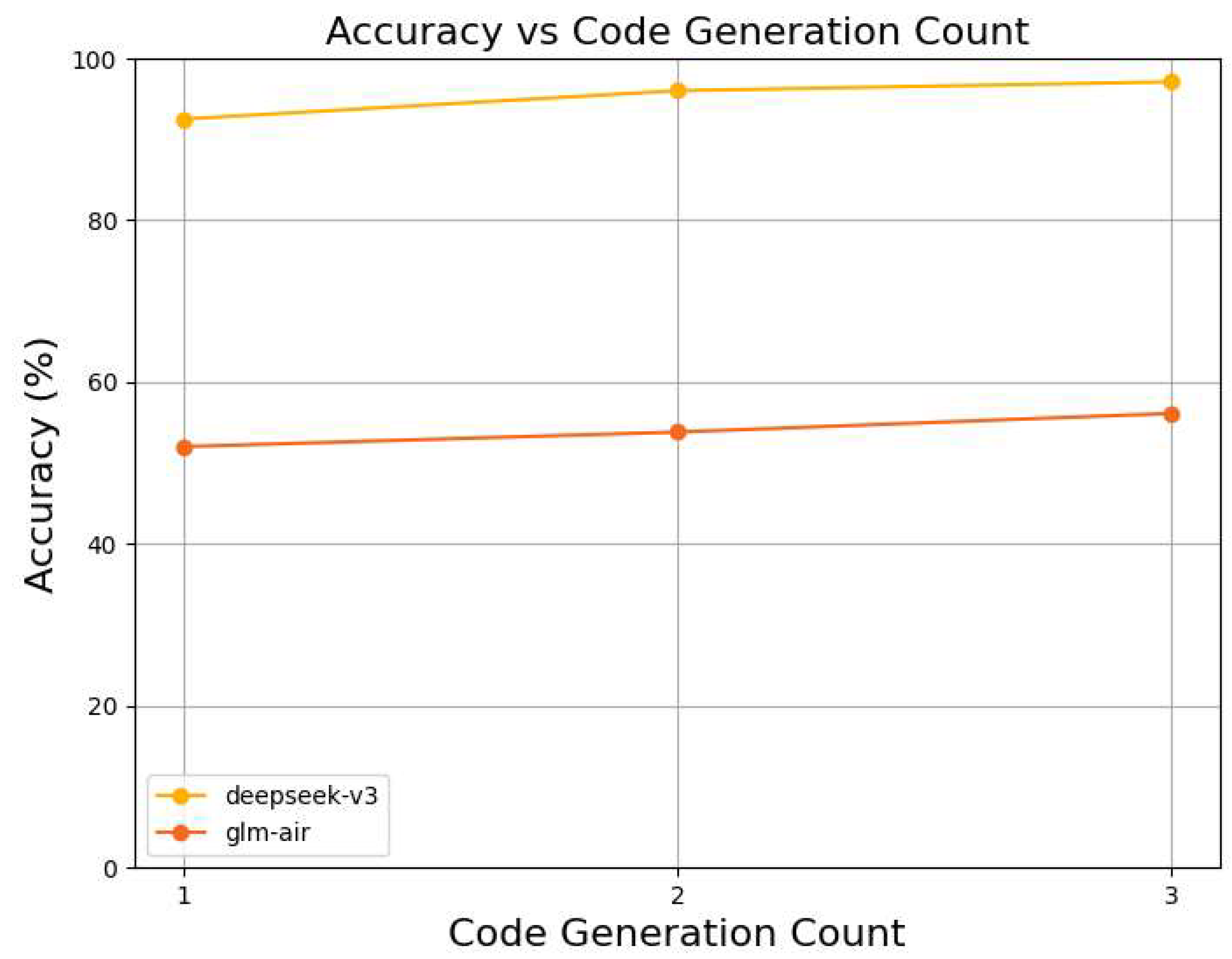
As illustrated in Figure 10, it has been verified that deepseek-v3 can perform the control code generation task quite effectively, achieving a correctness rate of 97.1% within three iterations. glm-4 air can only achieve an accuracy of 56.1% in the end. In the experiment, the deepseek-v3 model takes about 5 min to complete one control code generation process, while a professional engineer takes about 15 min to accomplish the same task. This results in an approximately 200% improvement in control code generation efficiency for a single room. It is important that since the large language model can be invoked in parallel, the code for each room can theoretically be generated simultaneously, leading to extremely high efficiency in code generation.
The detailed analysis by criterion is shown below.
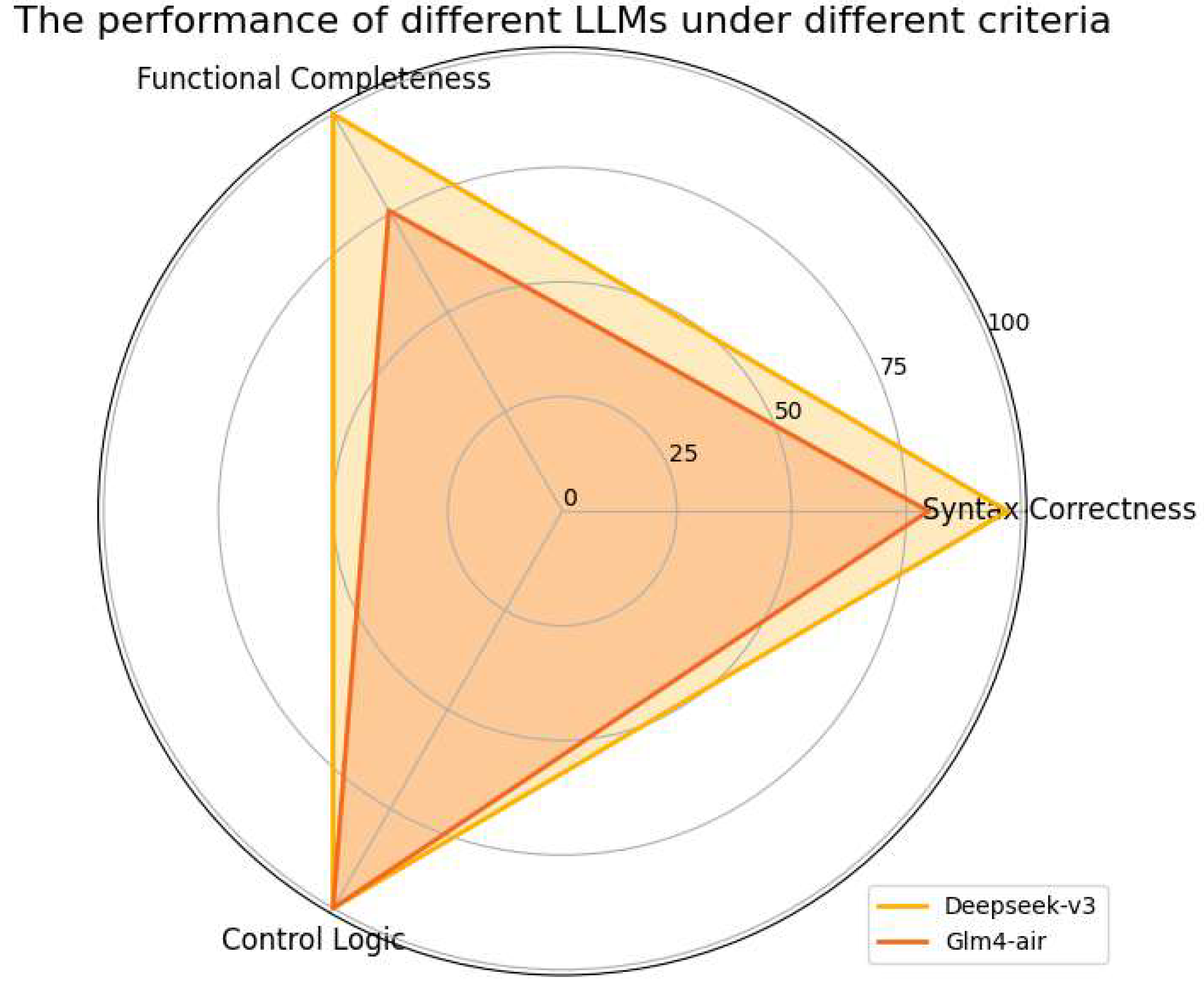
As illustrated in Figure 11, deepseek-v3 only has issues with syntax correctness but achieves a passing rate of 97.1%. The passing rate for glm4-air in terms of syntax correctness is 79.8%, and its passing rate for functional completeness is 75.7%. It is worth noting that both models achieved a 100% passing rate in terms of device security and control logic, as the example code provided a good framework and demonstration, requiring no reasoning or generation from the large language models.

3.3.3. Scalability

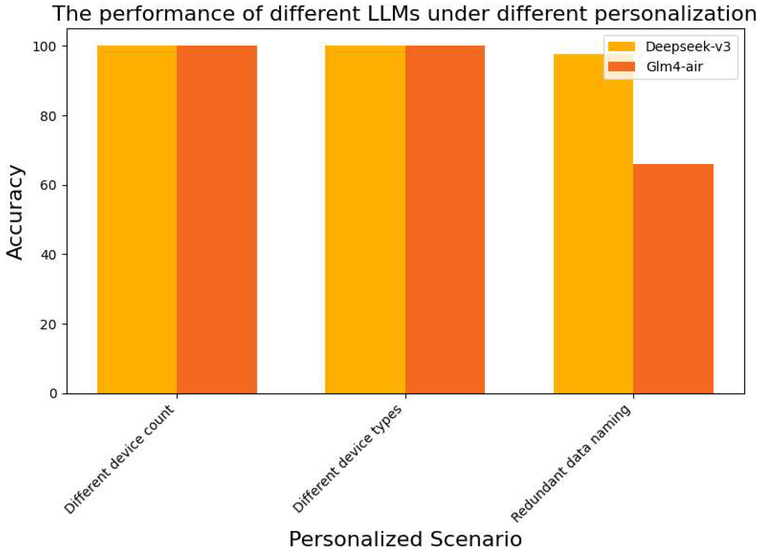
In this experiment, we only recorded an error when there was a personalization that caused the code to fail due to that personalization. It can be observed that all errors occurred in cases of redundant data naming. As illustrated in Figure 12, deepseek-v3 achieved a passing rate of 97.6% under this personalization, while Glm4-air had a passing rate of 65.9%. Upon reviewing the generated code, it was found that the error in glm4-air was due to a conflict between the prompt instructions and parameter naming rules. In such cases, glm4-air has a certain chance of autonomously modifying the parameter names, while not firmly executing the instructions. The experimental results indicate that this method can effectively address personalized project situations.

3.3.4. Reliability

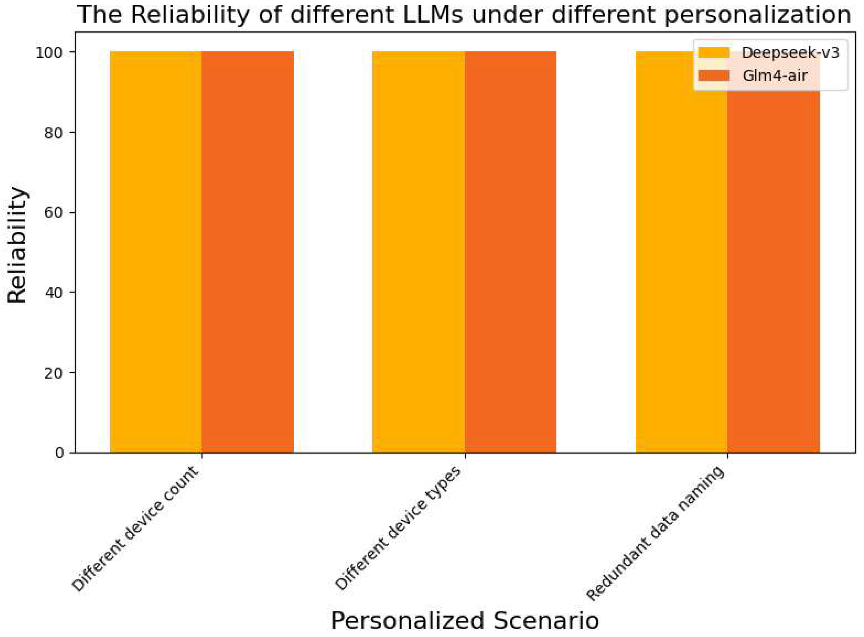
In the experiment, we tested the impact of the generated code on equipment safety, specifically whether the code could implement device chain control in the correct start-stop sequence and whether it could ensure a safe stop in the event of a device failure. As illustrated in Figure 13, the experimental results are as follows:
In the experiment, we only considered code verified for accuracy because unverified code would not be deployed in actual projects and would not impact equipment safety. The results indicate that, in all three personalized scenarios, regardless of the large language model used, the correct control sequence was achieved with 100% accuracy. This is because all rooms were in similar operating conditions. Although there were personalized situations, they did not affect the control sequence. When provided with similar cases as guidance, the large language model was able to understand the control sequence without interference, thus ensuring safe control.

3.4. Other Experiments

3.4.1. The Impact of Code Segment Splitting

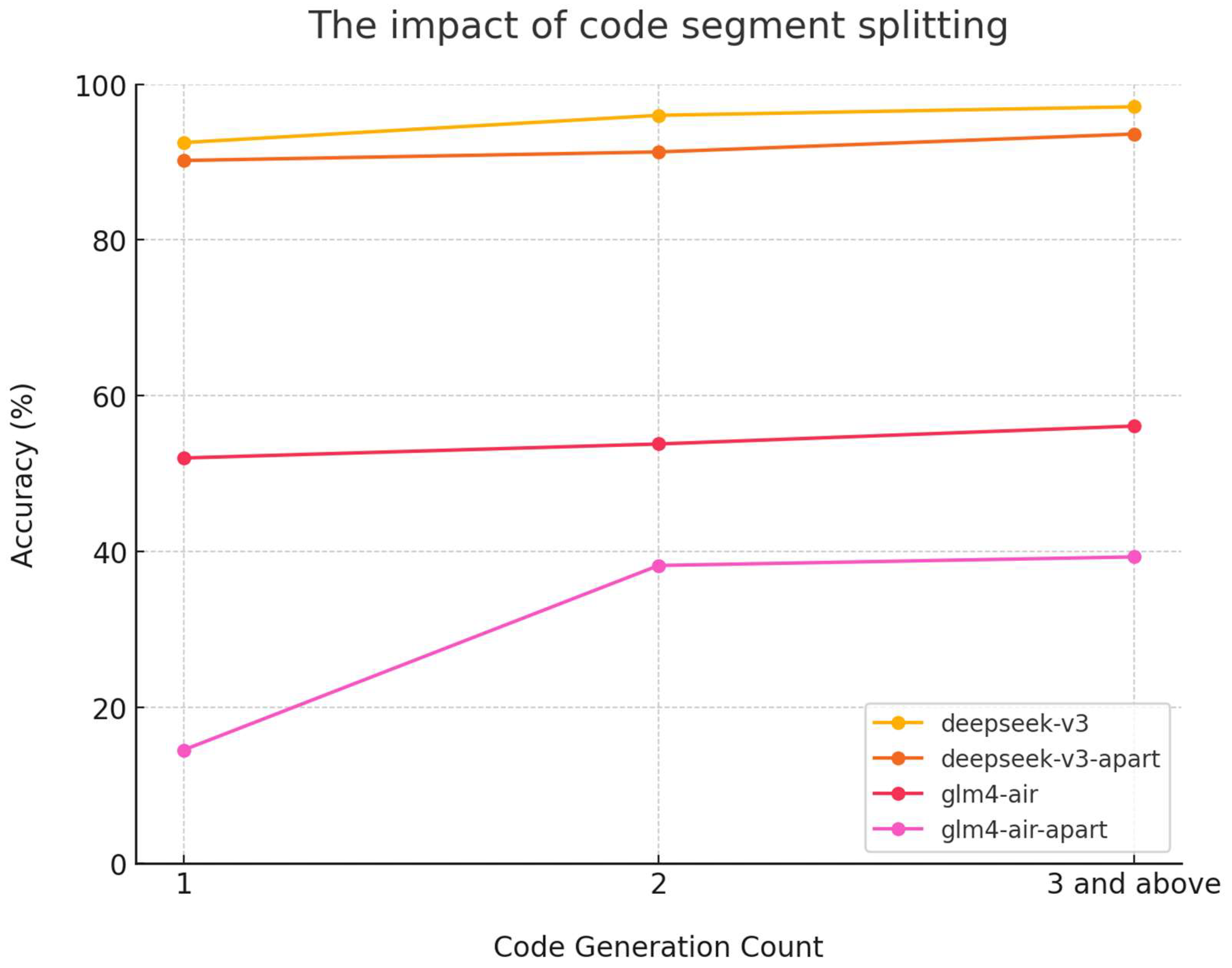
In this study, we experimented with splitting complex code into functional blocks, generating each block separately, and then using a large language model to stitch them together. As illustrated in Figure 14, the comparison with the original method is shown below.
In the experiment, Deepseek-v3 still performed well, with a slight decrease in accuracy. However, models with weaker capabilities were more significantly affected, with accuracy dropping noticeably from 56.1% to 39.3%. This result demonstrates that for structurally complex code, generating in batches and then stitching them together may affect the accuracy of the output. The impact is more pronounced for models with weaker capabilities. The reason is that when generating in batches, the model’s output becomes unstable due to incomplete context. Furthermore, when stitching the code, the structural relationships between functional blocks must be considered, which still tests the model’s ability to generate long and coherent code.
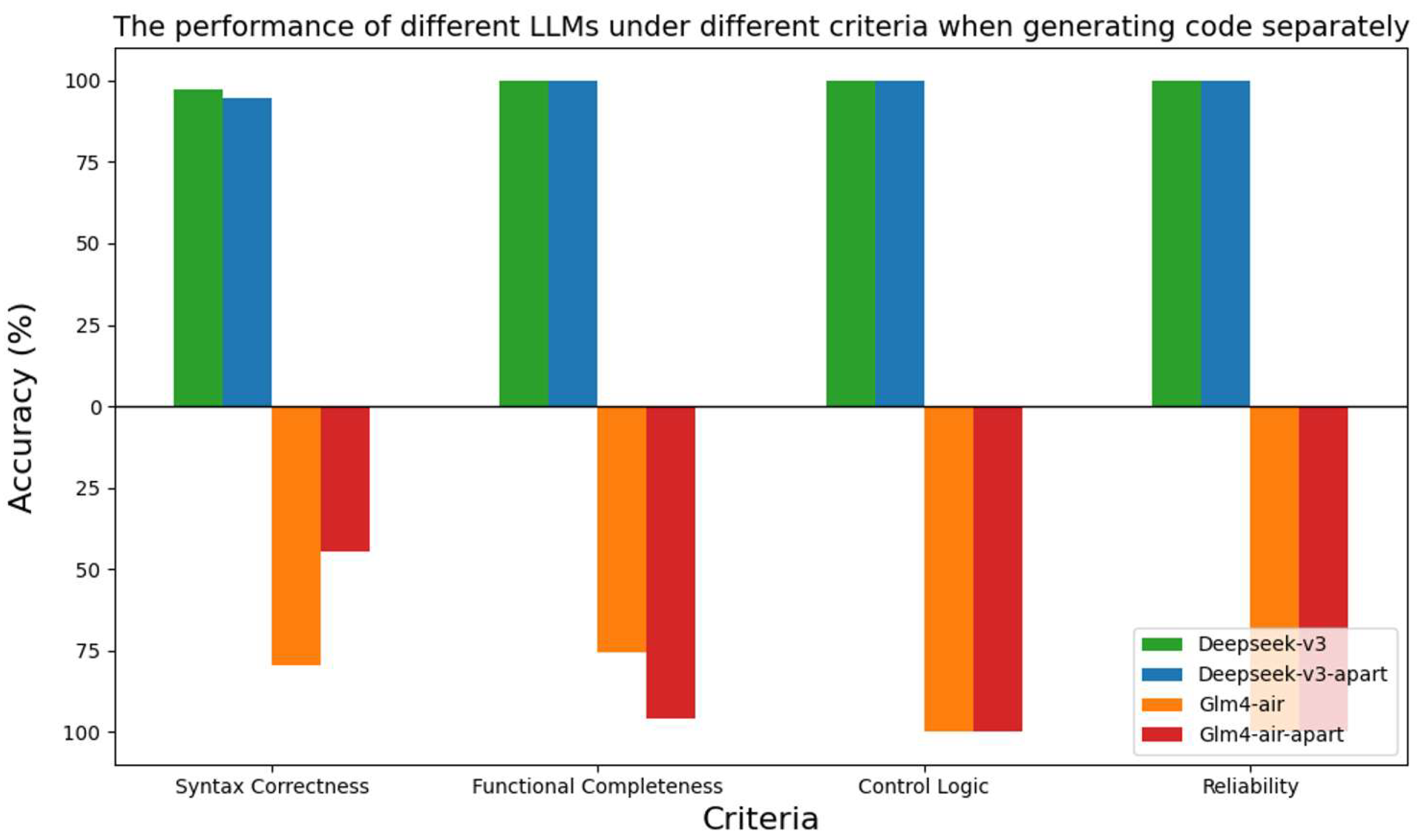
As illustrated in Figure 15, the detailed analysis of different criteria is shown below.
Deepseek-v3 is only affected by syntax correctness, with its passing rate decreasing from 97.1% to 94.8%. For Glm4-air, the passing rate for syntax correctness dropped from 79.8% to 44.5%, while the passing rate for functional completeness increased from 75.7% to 96.0%. The passing rates for both models in terms of reliability and control logic remained unchanged at 100%. The experimental results indicate that for complex code structures, using a batch-generation method can effectively prevent the loss of functional blocks. However, it also poses a greater challenge to the ability of large models to handle structural concatenation.
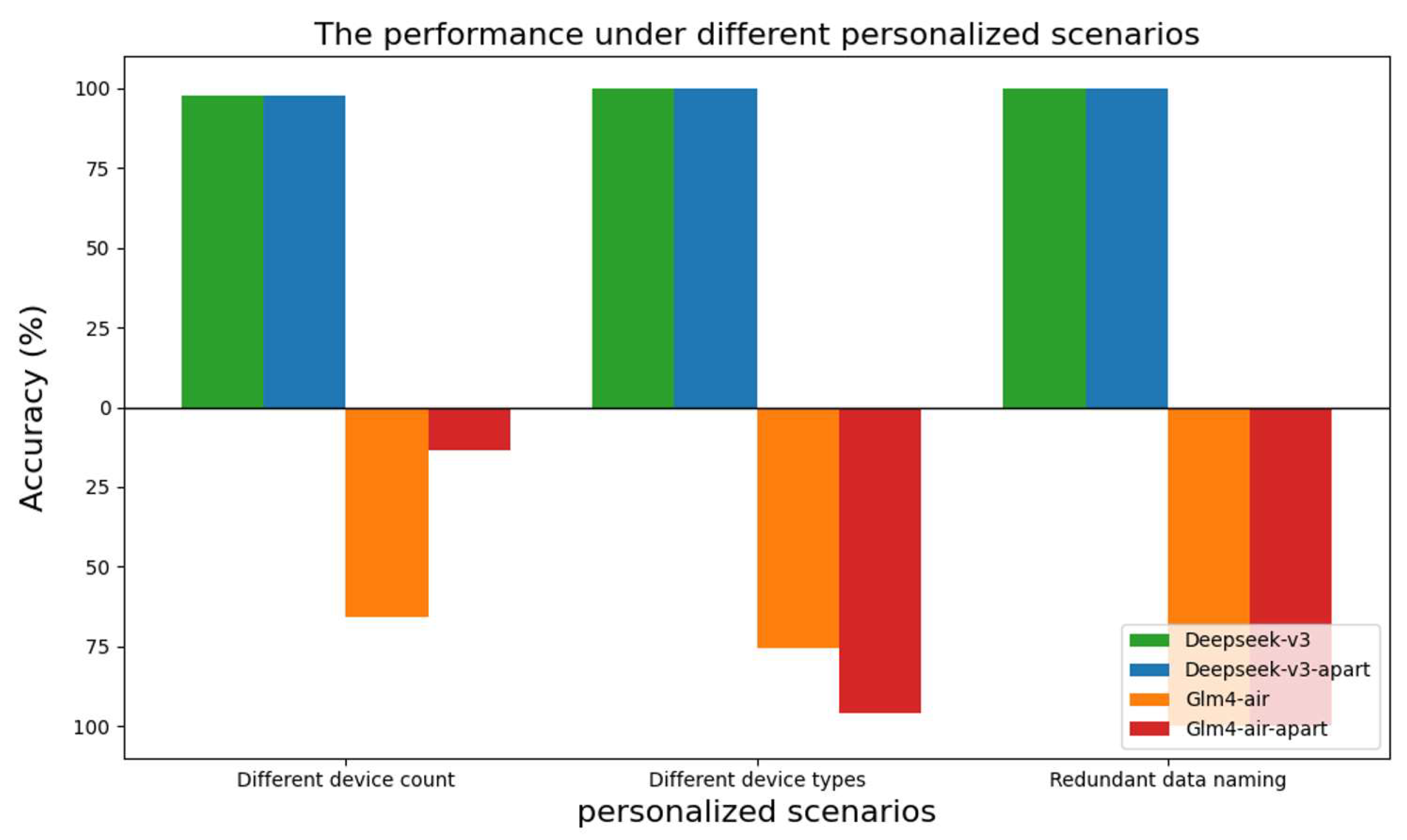
As illustrated in Figure 16, the performance under different personalized scenarios is as follows:
All errors occurred in cases of redundant data naming. Deepseek-v3 maintained a passing rate of 97.6% under this personalization, while Glm4-air’s passing rate dropped from 65.9% to 13.4%. The reason for this is that during concatenation, glm4-air again exhibited a lack of confidence in executing instructions, leading to a compounded error probability in both the generation and concatenation processes, causing a significant drop in the passing rate.

3.4.2. The Impact of Each Element in the Prompt on Accuracy

We conducted an ablation study examining the impact of domain knowledge, syntax hints, and examples on framework performance.
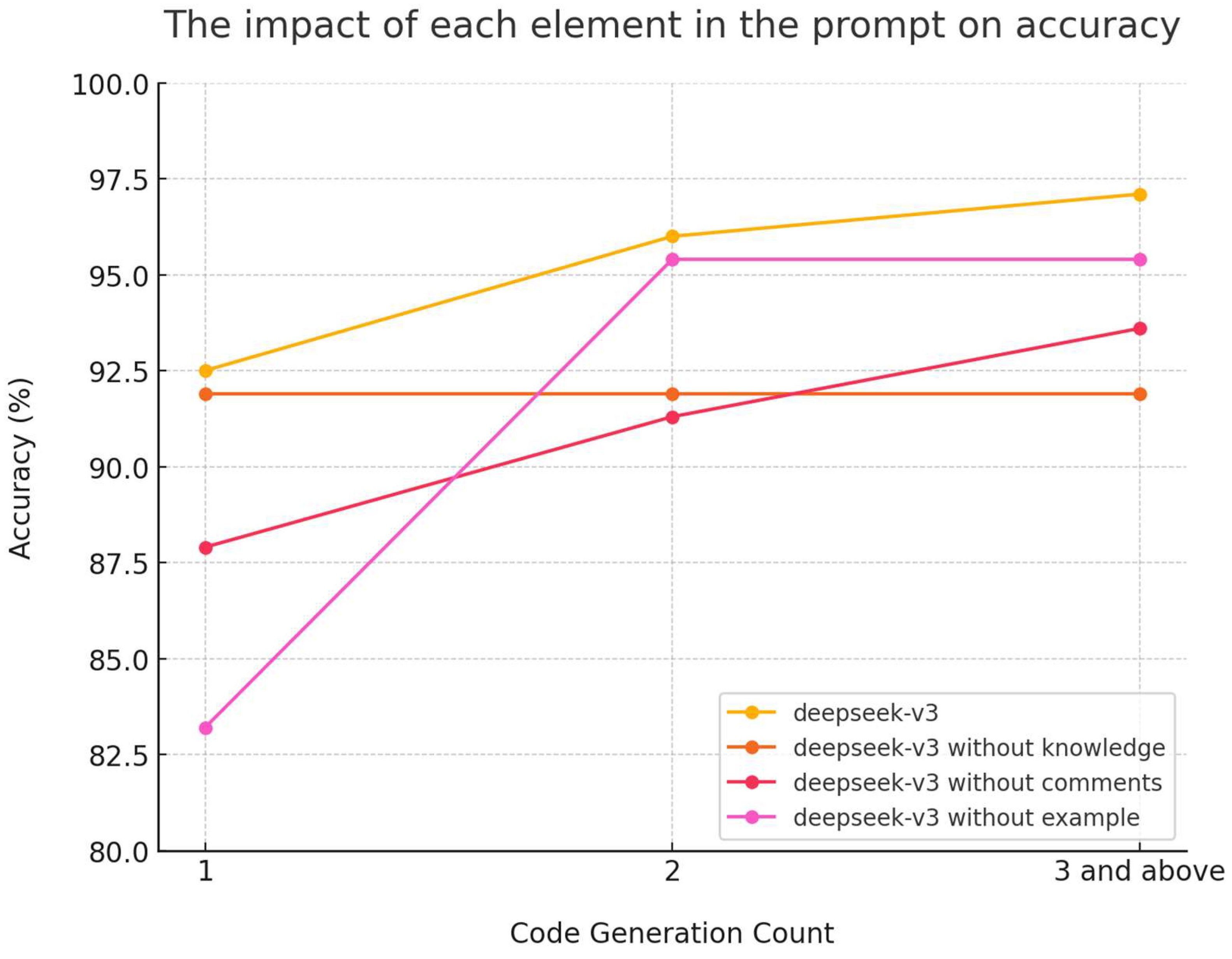
The experimental results indicate that the absence of knowledge, comments, and examples significantly reduces the accuracy of code generation. As illustrated in Figure 17, the lack of examples has a more substantial impact on the accuracy of the initial code generation, which is only 83.3%. However, through iterative guidance using domain knowledge, the code can be effectively corrected, ultimately reaching 95.5%. The absence of domain knowledge has a smaller effect on the initial generation, as the relevant case codes already contain this information, allowing the large model to directly summarize and apply it. Without domain knowledge guidance, the large model struggles to make accurate corrections to the code. The absence of syntax hints decreases the accuracy of the code throughout the entire process. These results demonstrate that our prompt design is well-structured and essential for achieving high accuracy in code generation.

3.5. Real-World Deployment

Building upon the simulation-based validation, this section describes the deployment of the proposed framework in the actual operating environment of the target building. The implementation establishes a complete closed-loop control chain spanning hardware sensing, data transmission, cloud-based code generation, and terminal execution. The framework has been successfully deployed across 381 ventilation subsystems within the target building.

3.5.1. Hardware Architecture and Deployment

The deployment began with hardware retrofitting of the target building, including the installation of a sensor network across all laboratories and common areas. Each room was equipped with temperature and humidity sensor nodes to continuously collect indoor environmental data. The sensor nodes are connected to room-level PLC controllers via wired or wireless interfaces. Each PLC controller is responsible for receiving sensor data, executing the locally deployed control code, and issuing regulation commands to terminal HVAC devices such as fan coil units, air valves, and variable frequency drives.
At the floor level, PLC controllers are aggregated through floor-level CPU controllers, which handle upward data collection from all PLCs on the same floor and downward distribution of control scripts. All floor-level CPU controllers are further connected to a building-wide master gateway, which consolidates cross-floor data and maintains external communication, uploading real-time operational data from the entire building to the cloud platform.
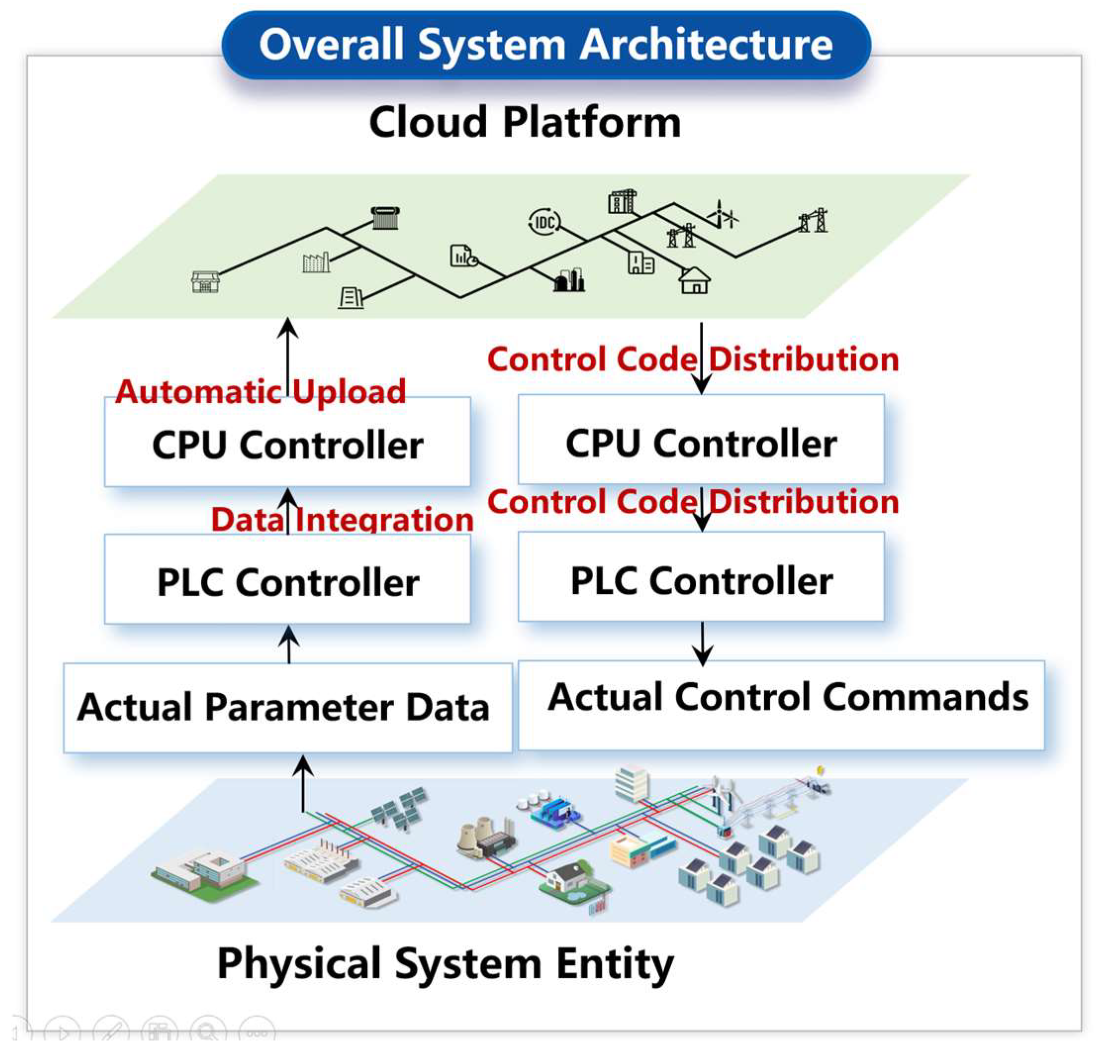
This hardware architecture forms a five-tier data chain: Sensor, PLC, Floor Gateway, Master Gateway, Cloud Platform. As illustrated in Figure 18, data flows upward through real-time collection and transmission, while control code and commands flow downward from the cloud platform through the gateway hierarchy to the PLC controllers, ultimately acting on the terminal HVAC devices.

3.5.2. Control Code Execution Mechanism

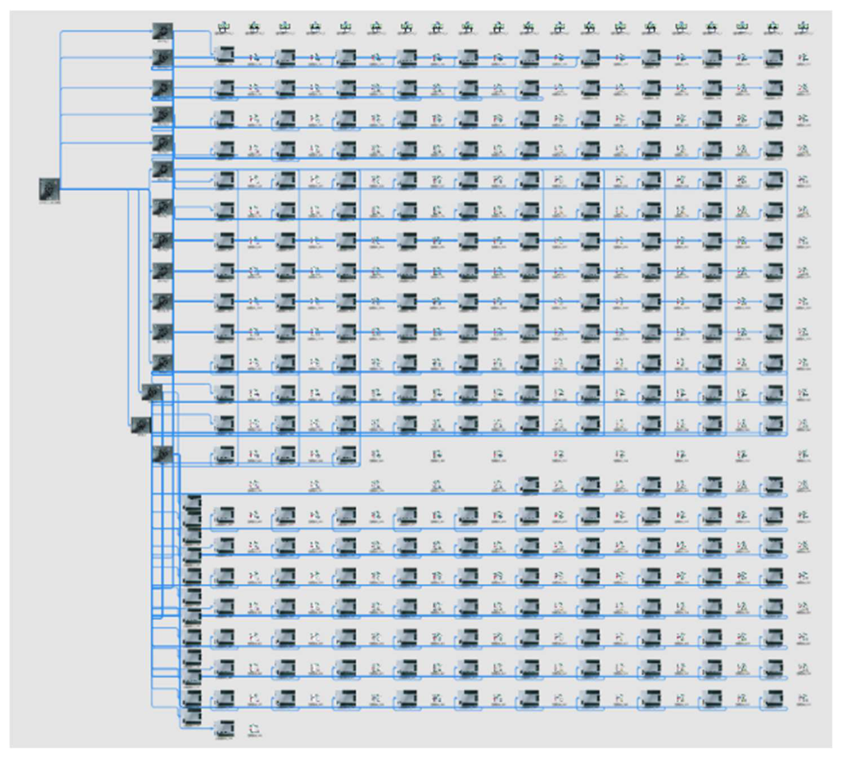
The core computation of control code generation is performed on the cloud platform. The cloud platform first establishes a digital mapping of the target building, binding room identifiers, sensor points, PLC addresses, and terminal HVAC devices across all thermal zones to form a complete equipment topology model. On this basis, the cloud platform receives real-time sensor data uploaded from the master gateway and treats each room as an independent unit for control code generation.
The specific workflow is as follows: the cloud platform reads the device configuration and parameter data of the target room, constructs a prompt context incorporating personalized knowledge, equipment parameters, and reference cases, and invokes the deployed LLM service to generate the corresponding control code. The generated code undergoes syntax validation and simulation-based safety verification before being automatically packaged as an executable script and distributed to the corresponding PLC controller via the gateway chain, completing a full code deployment cycle. This workflow is fully consistent with the iterative validation logic described in Section 2, with the simulation environment serving as the verification layer prior to real-world deployment.
In practice, code generation tasks for different rooms can be scheduled in parallel. The cloud platform dynamically allocates computational resources according to the processing status of each room, ensuring both generation quality and overall system throughput efficiency.
The proposed framework is designed to operate as a fully automated pipeline, requiring no mandatory user intervention during the iterative validation process. Upon completion of the automated code generation and validation cycle, users may optionally review the results and submit additional requirements or parameter adjustments for specific rooms if needed, triggering a new generation cycle for those rooms.
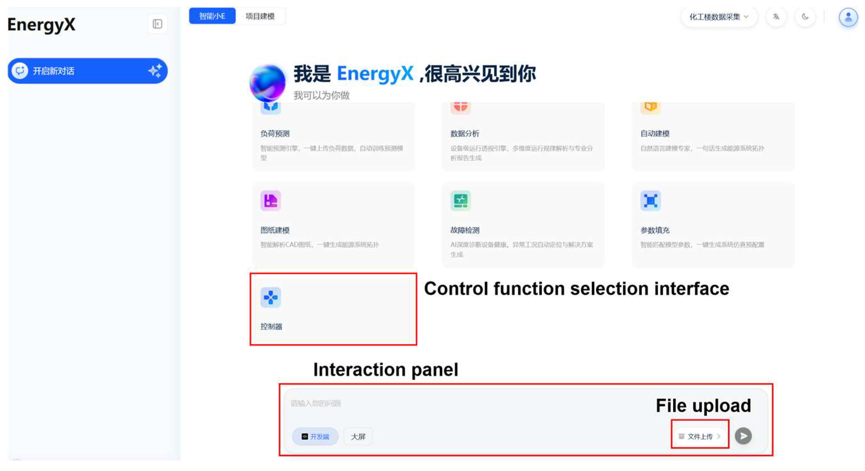
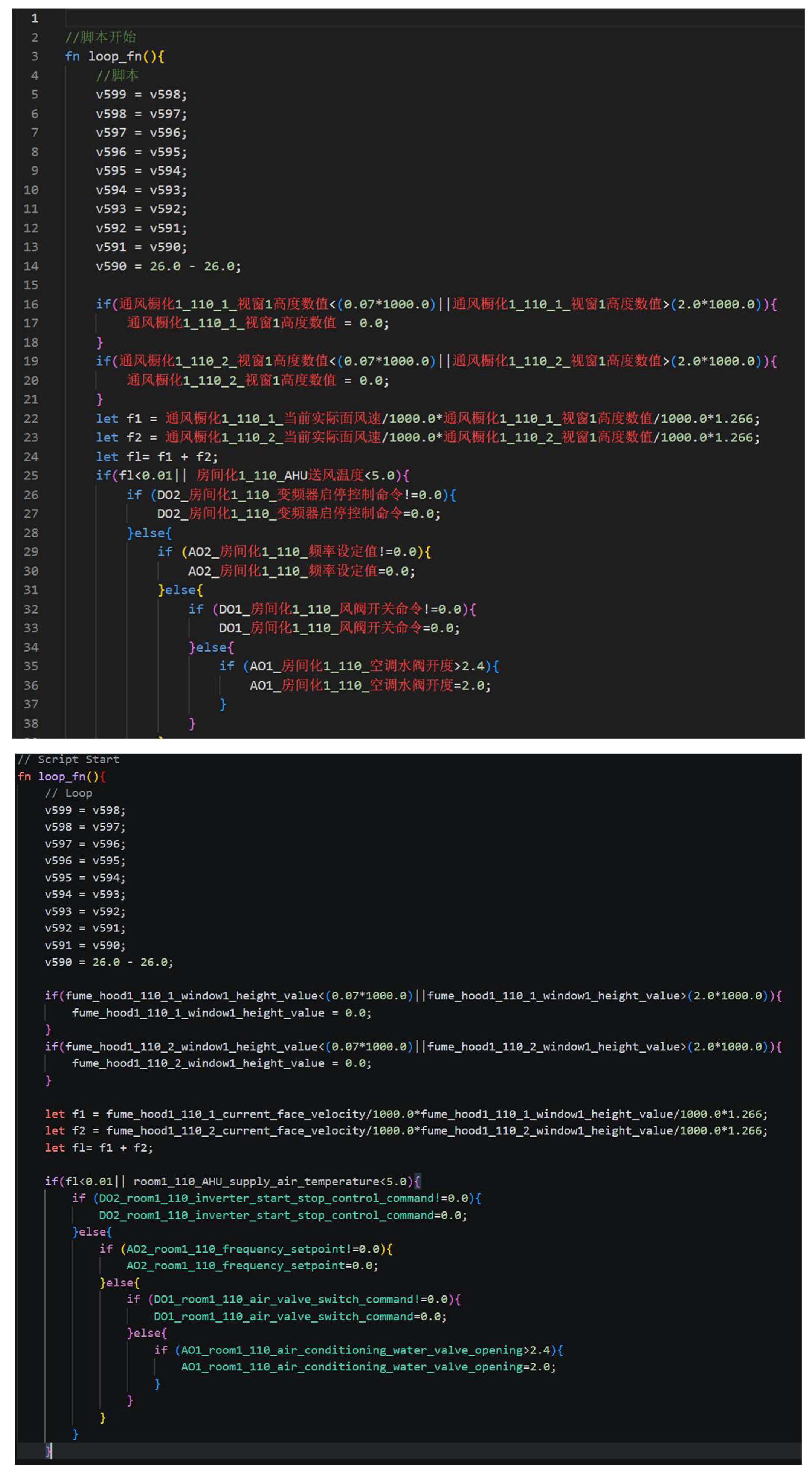
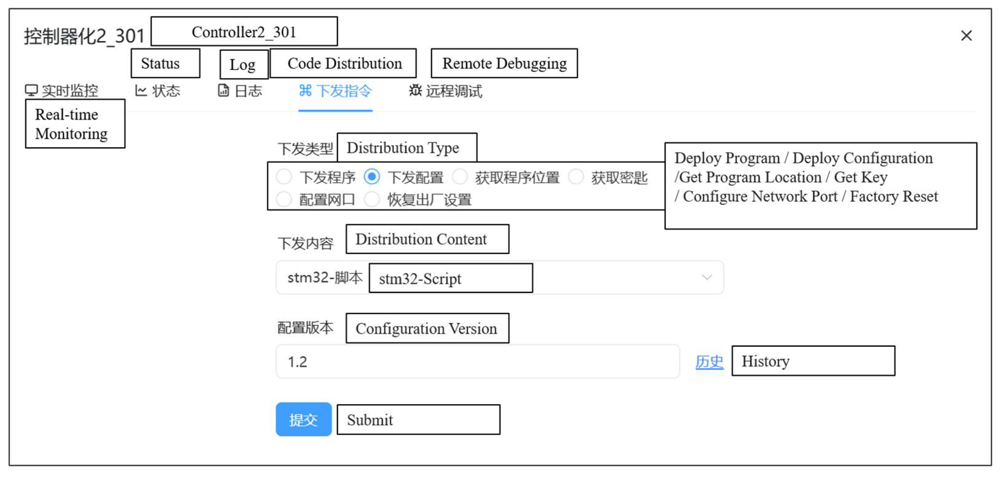
Since deployment, the system has been operating stably across all 381 ventilation subsystems without any control failures or equipment faults attributable to code errors. The generated control code has demonstrated consistent execution of device startup/shutdown sequences and interlock logic under varying operating conditions, confirming the reliability of the proposed framework in real-world engineering applications. Screenshots of the actual interface of the cloud platform are shown in Figure 19, Figure 20, Figure 21 and Figure 22.

4. Discussion

4.1. Advantages of the LLM-Based Method

The experimental results highlight three distinctive advantages of the proposed framework over traditional approaches.
In terms of accuracy, the framework achieves 97.1% overall code generation accuracy within three iterations, driven primarily by the strong reasoning and generalization capabilities of DeepSeek-V3. Notably, the gap between DeepSeek-V3 and GLM4-Air suggests that model capability plays a critical role in handling personalized scenarios, where rigid rule-based systems would typically require manual redesign.
In terms of efficiency, the framework reduces per-room code generation time from 15 min for expert manual coding to approximately 5 min, representing a threefold improvement. More importantly, the parallel invocation capability of LLMs allows simultaneous processing of multiple rooms, making the framework particularly advantageous for large-scale installations where traditional sequential approaches become prohibitively time-consuming.
In terms of generalization, the framework demonstrates strong adaptability across diverse personalization scenarios with only a single reference case. Even in the absence of case examples, the iterative correction mechanism guided by domain knowledge achieves 95.5% accuracy, indicating that the framework’s performance is robust to variations in available reference material.

4.2. Limitations

This study has several limitations. The method has only been tested in a single scenario type, and generalizability across different projects has not been verified. The method does not achieve 100% accuracy, and some rooms require multiple code generation attempts. It also relies on example cases to provide code frameworks for similar scenarios, and struggles with highly distinct control scenarios that still require manual initialization of the code framework.
It is worth noting that the primary focus of this study is on the generation of control code frameworks, particularly the safety-critical aspects such as device startup/shutdown sequences, interlock logic, and fault protection mechanisms, rather than fine-grained parameter tuning. However, the architecture of the proposed framework is designed with extensibility in mind. Notably, the framework incorporates a simulation platform that generates real-time operational data, which theoretically enables iterative parameter optimization through simulation-agent interaction, potentially improving tuning efficiency while reducing associated costs. However, the feasibility of directly applying large language models to parameter adjustment requires further validation, and alternative approaches such as integrating reinforcement learning or other optimization algorithms into the existing framework may be considered to achieve more precise parameter optimization. This represents a promising direction for future work, building upon the code generation foundation established in this study.

5. Conclusions

This study presents an LLM-based framework for automatic control code generation in HVAC systems, addressing the limitations of traditional template-based and model-driven approaches in handling large-scale personalized scenarios. By integrating RAG technology, simulation-based verification, and a multi-agent architecture, the framework achieves automated code generation without relying on manual intervention for each new project configuration.
Validation on a real-world project involving 173 laboratory rooms demonstrates that the framework achieves a code generation accuracy of 97.1% within three iterations, with an average processing time of 5 min per room. The framework has been further deployed across 381 ventilation subsystems, confirming its practical applicability in real engineering environments. Ablation studies reveal that case examples have the greatest impact on first-generation accuracy, while domain knowledge plays a critical role in iterative correction. Code segmentation experiments suggest that batch generation may reduce overall accuracy, particularly for models with weaker capabilities.
Despite these results, several limitations remain. The framework has only been tested in laboratory building scenarios, and its generalizability across different project types has not been fully verified. Additionally, the framework currently focuses on code framework generation, including device sequencing and interlock logic, rather than fine-grained parameter tuning. Future work will explore the integration of reinforcement learning for adaptive parameter optimization, as well as the extension of the framework to a broader range of HVAC system configurations.

Author Contributions

Conceptualization, R.J.; data curation, R.J.; formal analysis, R.J.; funding acquisition, R.J.; investigation, R.J.; methodology, R.J.; project administration, J.L.; resources, R.J.; software, J.H.; supervision, J.L.; validation, R.J.; visualization, K.X.; writing—original draft, R.J.; writing—review and editing, J.L. All authors have read and agreed to the published version of the manuscript.

Funding

This research received no external funding.

Data Availability Statement

The original contributions proposed in this study are included within the manuscript. For further inquiries, please contact the corresponding author.

Conflicts of Interest

The authors declare no conflicts of interest.

Abbreviations

The following abbreviations are used in this manuscript:
LLMLarge Language Model
HVACHeating, Ventilation and Air Conditioning
MBDModel-Based Design
RAGRetrieval-Augmented Generation

Appendix A

Appendix A contains a complete prompt example.
Table A1. Prompt example.
######## System
You are an expert in the HVAC field, proficient in writing control code for air conditioning terminals using the Rust language.
######## Task Description
Your task is to write a Rust program to control an air conditioning terminal to maintain a stable room temperature.
######## Scenario Description
The room you need to regulate has a fresh air unit that supplies air from outdoors and performs primary cooling. Indoors, there is a return air unit responsible for secondary cooling, and several fume hoods continuously exhaust air outdoors.
The outdoor temperature is unknown.
The user’s target temperature is unknown.
The target temperature is: 26.0 °C.
The room has 2 fume hoods, with face velocities of “fume_hood1_114_1_current_face_velocity” and “fume_hood1_114_2_current_face_velocity,” and cross-sectional heights of “fume_hood1_114_1_window1_height_value” and “fume_hood1_114_2_window1_height_value,” respectively. The width is fixed at 1.266 m.
You can control the fresh air unit to supply air indoors. The controllable variable is the inverter frequency: “AO2_room1_114_frequency_setpoint,” which is proportional to the air supply volume.
You can control the water valve opening: “AO1_room1_114_air_conditioning_water_valve_opening” to regulate the supply air temperature. The larger the opening, the lower the supply air temperature, and the smaller the opening, the higher the supply air temperature.
The following variables may have different room numbers, which is normal. Be sure to name them exactly as shown below.
You can observe the current supply air temperature: “room1_114_AHU_supply_air_temperature,” indoor temperature: “room1_113_fan_coil_return_air_temperature_2,” whether the air valve is open: “DO1_room1_114_air_valve_switch_command,” whether the inverter is on: “DO2_room1_114_inverter_start_stop_control_command,” the feedback of the water valve opening: “AI7_room1_114_fresh_air_unit_water_valve_opening_feedback,” the water valve opening setpoint: “AO1_room1_114_air_conditioning_water_valve_opening,” and the feedback of the inverter frequency: “room1_114_frequency_feedback.” The correction factor for fume hood data is 1000.0, which may differ from the example. Use this value for correction.
######## Rules
The following safety rules must be followed:
  • The air valve must be opened before the inverter is turned on.
  • The air valve must be closed after the inverter is turned off.
  • The water valve must be opened before the air valve is opened.
  • The water valve must be closed after the air valve is closed.
  • The system must be shut down when the supply air temperature approaches freezing point.
########## Requirements
Indoor air pressure and temperature must be maintained, meaning the fresh air unit’s supply volume must be close to the fume hoods’ exhaust volume.
The supply air temperature must be lower than the indoor temperature; otherwise, condensation may occur, leading to user complaints.
The supply air temperature must not be significantly lower than the user’s setpoint; otherwise, it may cause user complaints.
You must return a single function named ‘loop_fn’ and provide a concise description in the comments. Please return the result to me in XML format as follows:
<Code Start>
……
<Code End>
Where ‘……’ contains only the code, with no additional information. To ensure direct compilation of the code in ‘……,’ provide only the single Rust function named ‘loop_fn’ and its comments. Do not include any other text.
No explanation is needed!
######### Example
The example below is highly similar to the target function. You only need to replace the variable names and note any changes in the number of variables. Be sure to follow the structure, logic, and generic variable names provided in the example!
The room you need to regulate has a fresh air unit that supplies air from outdoors and performs primary cooling. Indoors, there is a return air unit responsible for secondary cooling, and several fume hoods continuously exhaust air outdoors.
The outdoor temperature is unknown.
The user’s target temperature is unknown.
The average room temperatures recorded in the past few days were: 24 °C, 24.6 °C, 24.4 °C.
The room has 2 fume hoods, with face velocities of “fume_hood1_110_1_current_face_velocity” and “fume_hood1_110_2_current_face_velocity,” and cross-sectional heights of “fume_hood1_110_1_window1_height_value” and “fume_hood1_110_2_window1_height_value,” with a constant width of 1.286 m.
You can control the fresh air unit to supply air indoors. The controllable variable is the inverter frequency pv, which is proportional to the air supply volume.
You can control the water valve opening “AO1_room1_110_air_conditioning_water_valve_opening” to regulate the supply air temperature “room1_110_AHU_supply_air_temperature.” The larger the opening “AO1_room1_110_air_conditioning_water_valve_opening,” the lower the supply air temperature “room1_110_AHU_supply_air_temperature,” and the smaller the opening “AO1_room1_110_air_conditioning_water_valve_opening,” the higher the supply air temperature “room1_110_AHU_supply_air_temperature.”
You can observe the current supply air temperature “room1_110_AHU_supply_air_temperature,” indoor temperature “room1_110_return_air_temperature_sensor,” whether the air valve is open “DO1_room1_110_air_valve_switch_command,” whether the inverter is on “DO2_room1_110_inverter_start_stop_control_command,” the feedback of the water valve opening “AI7_room1_110_fresh_air_unit_water_valve_opening_feedback,” and the water valve opening setpoint “AO1_room1_110_air_conditioning_water_valve_opening.”
######### Code Example
<Code Start>
Function loop_fn()
    // Initialize values
    InitializePreviousValues()
    // Calculate temperature difference
    v590 = CalculateTemperatureDifference()
    // Correct data for window height
    CorrectWindowHeightValues()
    // Calculate total ventilation volume
    f1, f2, fl = CalculateVentilationVolume()
    // Determine if air supply is needed based on air volume and temperature
    If IsAirSupplyRequired(fl) Then
        // Check and manage inverter, frequency setpoint, and air valve
        ManageInverterAndAirValve()
    Else
        // Manage system start: open water valve and air valve
        If IsSystemStarting() Then
            OpenWaterValve()
            If IsWaterValveOpen() Then
                OpenAirValve()
                If IsAirValveOpen() Then
                    StartInverterAndAdjustFrequency()
                    AdjustWaterValveOpening()
                End If
            End If
        End If
    End If
End Function<Code End>

References

  1. Zhang, C.; Li, J.; Zhao, Y.; Li, T.; Chen, Q.; Zhang, X.; Qiu, W. Problem of data imbalance in building energy load prediction: Concept, influence, and solution. Appl. Energy 2021, 297, 117139. [Google Scholar] [CrossRef]
  2. Gu, J.; Wang, J.; Qi, C.; Min, C.; Sundén, B. Medium-term heat load prediction for an existing residential building based on a wireless on-off control system. Energy 2018, 152, 709–718. [Google Scholar] [CrossRef]
  3. Pérez-Lombard, L.; Ortiz, J.; Pout, C. A review on buildings energy consumption information. Energy Build. 2008, 40, 394–398. [Google Scholar] [CrossRef]
  4. Krstić-Furundžić, A.; Vujošević, M.; Petrovski, A. Energy and environmental performance of the office building facade scenarios. Energy 2019, 183, 437–447. [Google Scholar] [CrossRef]
  5. Lee, D.; Cheng, C.-C. Energy savings by energy management systems: A review. Renew. Sustain. Energy Rev. 2016, 56, 760–777. [Google Scholar] [CrossRef]
  6. Schumacher, F.; Fay, A. Formal representation of GRAFCET to automatically generate control code. Control Eng. Pract. 2014, 33, 84–93. [Google Scholar] [CrossRef]
  7. Li, Z.; Jia, H.; Zhang, Y.; Chen, T.; Yuan, L.; Cao, L.; Wang, X. AutoFFT: A template-based FFT codes auto-generation framework for ARM and X86 CPUs. In Proceedings of the International Conference for High Performance Computing, Networking, Storage, and Analysis 2019, Denver, CO, USA, 17–22 November 2019. [Google Scholar]
  8. Hu, K.; Duan, Z.; Wang, J.; Gao, L.; Shang, L. Template-based AADL automatic code generation. Front. Comput. Sci. 2019, 13, 698–714. [Google Scholar] [CrossRef]
  9. Yue, W.; Dan, L.I.; Xiao, D.; Zhigang, L. Energy storage converter study based on MATLAB auto code generation. Power Electron. 2014, 48, 3. [Google Scholar] [CrossRef]
  10. O’Halloran, C. Automated verification of code automatically generated from Simulink. Autom. Softw. Eng. 2013, 20, 237–264. [Google Scholar] [CrossRef]
  11. Lee, S.C.; Gagas, B.S.; Wang, Y.; Lorenz, R.D. Implementing advanced AC drive controls using auto-coding methods. In Proceedings of the 18th International Conference on Electrical Machines and Systems (ICEMS), Pattaya, Thailand, 25–28 October 2015. [Google Scholar]
  12. Vaswani, A.; Shazeer, N.; Parmar, N.; Uszkoreit, J.; Jones, L.; Gomez, A.N.; Kaiser, Ł.; Polosukhin, I. Attention is all you need. Adv. Neural Inf. Process. Syst. 2017, 30, 5998–6008. [Google Scholar]
  13. Lin, T.; Wang, Y.; Liu, X.; Qiu, X. A survey of transformers. arXiv 2022, arXiv:2106.04554. [Google Scholar] [CrossRef]
  14. Brown, T.B.; Mann, B.; Ryder, N.; Subbiah, M.; Kaplan, J.D.; Dhariwal, P.; Neelakantan, A.; Shyam, P.; Sastry, G.; Askell, A.; et al. Language models are few-shot learners. Adv. Neural Inf. Process. Syst. 2020, 33, 1877–1901. [Google Scholar]
  15. Chowdhery, A.; Narang, S.; Devlin, J.; Bosma, M.; Mishra, G.; Roberts, A.; Barham, P.; Chung, H.W.; Sutton, C.; Gehrmann, S.; et al. PaLM: Scaling language modeling with pathways. arXiv 2023, arXiv:2204.02311. [Google Scholar]
  16. Chung, H.W.; Hou, L.; Longpre, S.; Zoph, B.; Tay, Y.; Fedus, W.; Li, Y.; Wang, X.; Dehghani, M.; Brahma, S.; et al. Scaling instruction-finetuned language models. arXiv 2022, arXiv:2210.11416. [Google Scholar] [CrossRef]
  17. Zhang, S.; Dong, L.; Li, X.; Zhang, S.; Sun, X.; Wang, S.; Li, J.; Hu, R.; Zhang, T.; Wu, F.; et al. Instruction Tuning for Large Language Models: A Survey. arXiv 2023, arXiv:2308.10792. [Google Scholar] [CrossRef]
  18. Wei, J.; Wang, X.; Schuurmans, D.; Bosma, M.; Xia, F.; Chi, E.; Le, V.Q.; Zhou, D. Chain-of-thought prompting elicits reasoning in large language models. Adv. Neural Inf. Process. Syst. 2022, 35, 24824–24837. [Google Scholar]
  19. Tarassow, A. The potential of LLMs for coding with low-resource and domain-specific programming languages. arXiv 2023, arXiv:2307.13018. [Google Scholar]
  20. Liu, Z.H.; Zeng, R.N.; Wang, D.X.; Peng, G.Y.; Wang, J.Y.; Liu, Q.; Liu, P.Y.; Wang, W.H. Agents4PLC: Automating Closed-loop PLC Code Generation and Verification in Industrial Control Systems using LLM-based Agents. arXiv 2024, arXiv:2410.14209. [Google Scholar] [CrossRef]
  21. Fu, X.Y.; Laskar, M.T.R.; Chen, C.; TN, S.B. Are Large Language Models Reliable Judges? A Study on the Factuality Evaluation Capabilities of LLMs. arXiv 2023, arXiv:2311.00681. [Google Scholar] [CrossRef]
  22. Bran, A.M.; Cox, S.; Schilter, O.; Baldassari, C.; White, A.D.; Schwaller, P. Augmenting large language models with chemistry tools. Nat. Mach. Intell. 2024, 6, 525–535. [Google Scholar] [CrossRef]
  23. Ji, Y.L.; Shen, F.C.; Wu, J.; Xie, Q.J.; Zhang, Y. Linear Reasoning vs. Proof by Cases: Obstacles for Large Language Models in FOL Problem Solving. arXiv 2026, arXiv:2602.20973. [Google Scholar] [CrossRef]
  24. Lee, J.; Yoon, W.; Kim, S.; Kim, D.; Kim, S.; So, C.H.; Kang, J. BioBERT: A pre-trained biomedical language representation model for biomedical text mining. Bioinformatics 2020, 36, 1234–1240. [Google Scholar] [CrossRef]
  25. Domkundwar, I.; NS, M.; Bhola, I.; Kochhar, R. Safeguarding AI agents: Developing and analyzing safety architectures. arXiv 2024, arXiv:2409.03793. [Google Scholar]
  26. Lewis, P.; Perez, E.; Piktus, A.; Petroni, F.; Karpukhin, V.; Goyal, N.; Küttler, H.; Lewis, M.; Yih, W.; Rocktäschel, T.; et al. Retrieval-augmented generation for knowledge-intensive NLP tasks. Adv. Neural Inf. Process. Syst. 2020, 33, 9459–9474. [Google Scholar]
  27. Pan, J.; Liang, W.S.; Yidi, Y. RAGLog: Log anomaly detection using retrieval augmented generation. In Proceedings of the IEEE World Forum on Public Safety Technology (WFPST), Herndon, VA, USA, 14–15 May 2024. [Google Scholar]
  28. Zhu, P.; Chen, W.; Chen, D.; Liu, J.; Liu, Z.; Liu, Y.; Lin, G. An efficient query system for coal mine safety information based on retrieval-augmented language model. In Proceedings of the International Conference on Intelligent Computing 2024; Lecture Notes in Computer Science; Springer: Singapore, 2024; Volume 14876. [Google Scholar]
  29. Lee, Y. Developing a computer-based tutor utilizing generative AI and retrieval-augmented generation. Educ. Inf. Technol. 2024, 30, 7841–7862. [Google Scholar] [CrossRef]
  30. Posedaru, B.-S.; Pantelimon, F.V.; Dulgheru, M.N.; Georgescu, T.M. AI text processing using retrieval-augmented generation: Applications in business and education. In Proceedings of the International Conference on Business Excellence; Sciendo: Warsaw, Poland, 2024; Volume 18, pp. 209–222. [Google Scholar]
  31. Yu, W. Retrieval-augmented generation across heterogeneous knowledge. In Proceedings of the North American Chapter of the Association for Computational Linguistics: Human Language Technologies: Student Research Workshop, Seattle, WA, USA, 10–15 July 2022; pp. 52–58. [Google Scholar]
  32. Siddiq, M.L.; Casey, B.; Santos, J. A lightweight framework for high-quality code generation. arXiv 2023, arXiv:2307.08220. [Google Scholar] [CrossRef]
  33. Zhuang, C.; Liu, J.; Xiong, H.; Ding, X.; Liu, S.; Weng, G. Connotation, architecture and trends of product digital twin. Comput. Integr. Manuf. Syst. 2017, 23, 753–768. [Google Scholar]
  34. Zhang, W.; Wang, G.; Yan, Y.; Chu, H.; Wang, J.; Cao, Z. Intelligent test of spacecraft based on digital twin and multiple agent systems. Comput. Integr. Manuf. Syst. 2021, 27, 16–33. [Google Scholar]
  35. Jørgensen, B.N.; Howard, D.A.; Clausen, C.S.B.; Ma, Z. Digital twins: Benefits, applications and development process. In Proceedings of the Portuguese Conference on Artificial Intelligence 2023; Lecture Notes in Computer Science; Springer: Cham, Switzerland, 2023; Volume 14116. [Google Scholar]
  36. Lu, J.; Zheng, Z.; Langtry, M.; Jackson, M.; Zhao, Y.; Feng, C.; Zhang, R.; Zhang, C.; Zhang, J.; Choudhary, R. Automated building energy modeling for energy retrofits using a large language model-based multi-agent framework. iScience 2025, 28, 113867. [Google Scholar] [CrossRef]
  37. Lu, J.; Tian, X.; Feng, C.; Zhang, C.; Zhao, Y.; Zhang, Y.; Wang, Z. Clustering compression-based computation-efficient calibration method for digital twin modeling of HVAC system. In Proceedings of the Building Simulation; Tsinghua University Press: Beijing, China, 2023; Volume 16, pp. 997–1012. [Google Scholar]
  38. Lu, J.; Tian, X.; Zhang, C.; Zhao, Y.; Zhang, J.; Zhang, W.; Feng, C.; He, J.; Wang, J.; He, F. Evaluation of large language models (LLMs) on the mastery of knowledge and skills in the heating, ventilation and air conditioning (HVAC) industry. Energy Built Environ. 2024, 6, 875–892. [Google Scholar] [CrossRef]
  39. Zhang, S.; Mu, H.; Liu, T. Improving accuracy and generalizability via multi-modal LLMs collaboration. In Proceedings of the International Joint Conference on Neural Networks, Yokohama, Japan, 30 June–5 July 2024. [Google Scholar]
  40. Tan, J.C.M.; Motani, M. LLMs as a system of multiple expert agents: An approach to solve the ARC challenge. In Proceedings of the IEEE Conference on Artificial Intelligence (CAI), Singapore, 25–27 June 2024. [Google Scholar]
Figure 1. The multi-agent framework for automatic generation of HVAC system control code based on Large Language Models.
Buildings 16 01722 g001
Figure 2. Preliminary Knowledge Preparation.
Buildings 16 01722 g002
Figure 3. Prompt examples for Basic Model Generation.
Buildings 16 01722 g003
Figure 4. Prompt examples for Basic Control Code Generation.
Buildings 16 01722 g004
Figure 5. Prompt examples for modeling agent.
Buildings 16 01722 g005
Figure 6. Prompt examples for coding agent.
Buildings 16 01722 g006
Figure 7. Code validation and debugging process.
Buildings 16 01722 g007
Figure 8. Prompt examples for verification agent.
Buildings 16 01722 g008
Figure 9. Prompt examples for debugging agent.
Buildings 16 01722 g009
Figure 10. The relationship between code accuracy and the number of generations.
Buildings 16 01722 g010
Figure 11. The performance of different LLMs under different criteria.
Buildings 16 01722 g011
Figure 12. The performance of different LLMs under different personalization scenarios.
Buildings 16 01722 g012
Figure 13. The reliability of different LLMs under different personalization scenarios.
Buildings 16 01722 g013
Figure 14. The impact of code segment splitting on accuracy.
Buildings 16 01722 g014
Figure 15. Performance under different criteria when generating code separately.
Buildings 16 01722 g015
Figure 16. Performance under different personalized scenarios (code segment splitting).
Buildings 16 01722 g016
Figure 17. The impact of each element in the prompt on accuracy.
Buildings 16 01722 g017
Figure 18. Overall hardware architecture and control code distribution pathway of the system.
Buildings 16 01722 g018
Figure 19. User interaction interface.
Buildings 16 01722 g019
Figure 20. Cloud-based equipment mapping.
Buildings 16 01722 g020
Figure 21. Automatically generated code and its English translation (partial).
Buildings 16 01722 g021
Figure 22. Control code distribution interface.
Buildings 16 01722 g022
Table 1. Examples of the knowledge base and its contents.
CategoryExample
Fundamental physicsThe wet bulb temperature is usually lower than the dry bulb temperature.
Industry standardsTo ensure indoor CO2 concentration is below 1000 ppm, each person requires 30 m3/h of fresh air.
Equipment control rulesThe corresponding damper must be opened before turning on the VFD. The water valve must be opened before opening the damper.
Coding ruleFor Rust code, use “//” to start single-line comments. Comments should be concise and clearly describe the function.
Demonstration casesThe room has {equipment list}; controllable parameters: {list}; control code: {code}
Data transmission formatsFume hoods in room 1_XX transmit data in mm. Divide by 1000 to convert to meters.
Device listsRoom 1_XX has 2 fume hoods and 1 AHU.
Device parametersParameters in room 1_110: room1_110_air_conditioning_water_valve_opening; room1_110_AHU_supply_air_temperature; room1_110_return_air_temperature_sensor; …
Table 2. Personalization types and their impacts on code generation.
Personalization TypeImpacts on Code
Type 1: Unequal number of laboratory equipment (61 rooms)Code for calculating ventilation volume must be adjusted according to the amount of equipment
Type 2: Different models of fume hoods (65 rooms)Data validation parameters must be modified according to the fume hood data transmission protocol
Type 3: Data naming inconsistencies (82 rooms)Variable names must strictly follow the project description, even if a few variables deviate from other naming conventions
Table 3. Time consumption of generating control code using different methods.
MethodSingle Room (min)All Rooms (min)
LLM-based method (this work)55 × X/N (parallel)
Manual coding1515 × X
Template and parameter-based120 (fixed setup)
Model-Based Design (MBD)1010 × X
Here, X is the total number of rooms and N is the number of parallel LLM processes.
Disclaimer/Publisher’s Note: The statements, opinions and data contained in all publications are solely those of the individual author(s) and contributor(s) and not of MDPI and/or the editor(s). MDPI and/or the editor(s) disclaim responsibility for any injury to people or property resulting from any ideas, methods, instructions or products referred to in the content.