Article

Durability and Mechanical Performance of Sisal-Fiber-Reinforced Cementitious Composites for Permanent Formwork Applications

by
Igor Machado da Silva Parente
1,2,
Daniel Véras Ribeiro
2,
Ruan Carlos de Araújo Moura
3,* and
Paulo Roberto Lopes Lima
2,4,*
1
Postgraduate Program in Material and Engineering, University of São Paulo (USP), Pirassununga 13635-900, SP, Brazil
2
Postgraduate Program in Civil Engineering, Federal University of Bahia, Salvador 40210-630, BA, Brazil
3
Postgraduate Program in Science, Innovation and Modeling in Materials (PROCIMM), State University of Santa Cruz, Ilhéus 45662-900, BA, Brazil
4
Postgraduate Program in Civil and Environmental Engineering, State University of Feira de Santana, Feira de Santana 44036-900, BA, Brazil
*
Authors to whom correspondence should be addressed.
Buildings 2026, 16(8), 1628; https://doi.org/10.3390/buildings16081628
Submission received: 10 March 2026 / Revised: 10 April 2026 / Accepted: 15 April 2026 / Published: 21 April 2026
(This article belongs to the Special Issue Advanced Composite Materials for Sustainable Construction)

Abstract

Reinforced concrete structures must balance immediate structural performance with long-term durability against environmental degradation, particularly carbonation-induced corrosion. While traditional cast-in-place concrete covers serve as the primary barrier, their substitution with prefabricated permanent formworks made of fiber-reinforced cementitious composites often fails to provide the necessary protective qualities required for aggressive environments. This study evaluates the durability and mechanical behavior of sisal-fiber-reinforced cementitious composites specifically engineered for use as permanent formwork. Short sisal fibers, treated by hornification to enhance dimensional stability and fiber–matrix adhesion, were incorporated at dosages of 2%, 4%, and 6% by weight. The experimental program included tests for water absorption, ultrasonic pulse velocity, axial compression, three-point flexural strength, and accelerated carbonation. The results indicated that composites with 2% and 4% of fibers exhibited reduced water absorption, sorptivity, compressive strength, and modulus of elasticity compared to the reference cement matrix. Residual stress values further demonstrated that the composites maintain significant post-cracking strength and stress transfer capacity, confirming their viability for structural elements. Although sisal-fiber-reinforced cementitious composites exhibit higher porosity and water absorption than conventional concrete used as reinforcement cover, they show sufficient resistance to carbonation to ensure a service life exceeding 50 years for reinforced concrete elements.

1. Introduction

Reinforced concrete (RC) is one of the most widely used materials in the world and has diverse applications in civil engineering, including infrastructure projects, bridges, and skyscrapers. To make the construction process faster and more efficient, the use of prefabricated permanent formwork systems for producing reinforced concrete beams, slabs, walls, and columns has increased. These systems improve construction productivity by reducing the labor and shoring required to support conventional formwork. In addition, it provides greater geometric homogeneity and better surface finish of the structural elements.
However, permanent formwork becomes part of the structure itself, replacing the concrete cover that protects the reinforcement from the action of external aggressive agents, as shown in Figure 1. Therefore, the material used in the formwork must ensure chemical resistance to carbonation and to the penetration of aggressive ions comparable to that of conventional concrete. This requirement is essential because reinforcement corrosion is estimated to incur an annual cost equivalent to about 3.5% of the global gross domestic product [1]. This problem can be mitigated throughout the service life of reinforced concrete structures by providing concrete cover with adequate thickness and quality to protect the reinforcement, as specified in structural design standards.
Different materials have been used as permanent formwork for beams [3,4,5]. The advantages of using ferrocement permanent formwork for the production of reinforced concrete beams and columns have been reported by several researchers [6,7,8]. According to [9], beams produced with ferrocement permanent formwork exhibit higher flexural strength, first-crack strength, and energy absorption capacity compared with conventional reinforced concrete beams. However, the concrete cover provided to the steel mesh used in ferrocement formwork is often insufficient to ensure adequate durability, which limits its application due to the risk of corrosion. Corrosion of the mesh can lead to generalized cracking of the ferrocement, resulting in loss of strength and ductility [10]. The effect of using ferrocement formwork on the durability of reinforced concrete structures was investigated by [11], who showed that reduced porosity, lack of homogeneity, and the presence of microcracks in the cement matrix and in the interfacial transition zone can influence the durability performance of the system.
To ensure greater durability of permanent formwork, ferrocement reinforcement has been replaced by carbon fabrics, polymeric fibers, or glass fibers. Fabric-reinforced panels with carbon fibers used as permanent formwork for slabs have shown an increase in cracking load and ductility of structural elements [12], especially when surface treatments are applied to the inner face to improve bonding with the cast-in-place concrete [13].
Permanent formworks made of ultra-high-toughness cementitious composites (UHTCCs) reinforced with polyvinyl alcohol (PVA) fibers were produced by [14]. Due to the strain-hardening behavior of UHTCCs, these formworks can improve crack control and enhance the tensile performance of reinforced concrete beams compared with conventional reinforced concrete elements. Similarly, Leung et al. [15] developed permanent formworks using pseudo-ductile cementitious composites (PDCCs) reinforced with PVA fibers and showed that the multiple cracking behavior of the formwork under flexural loading reduces crack width. As a result, PDCC formwork can limit the penetration of aggressive agents and act as an effective protective layer against steel corrosion in reinforced concrete structures.
Glass fiber-reinforced cementitious composites were also investigated by [16], who demonstrated their feasibility as permanent formwork for slabs up to 200 mm thick. Although these studies highlight the potential of different materials for use as permanent formworks based on mechanical performance, little attention has been given to the effect of these systems on the durability of structural elements.
Biomaterials have increasingly been used in the production of cement-based construction elements to replace natural aggregates or polymeric fibers with materials that require lower energy for production, generate less CO2, and originate from renewable sources [17,18,19]. Using experimental, analytical, and numerical approaches, it was demonstrated that wood–cement composite panels can be used in permanent formwork systems up to 1.5 m in height.
Permanent formworks reinforced with long sisal fibers (900 mm) for floor slab production were evaluated by [2]. The formworks were manufactured in arch and trapezoidal shapes with lengths of 108 mm, widths up to 80 mm, and thicknesses of 20 mm. Flexural tests conducted on the permanent formworks and on a full-scale slab produced with these systems indicated that sisal-fiber-reinforced cementitious composites are suitable for use in permanent formwork systems.
Lima et al. [2] produced permanent formworks in sisal–cement composites in prefabricated slabs, replacing conventional construction elements of expanded polystyrene (EPS) or ceramic blocks. The composite elements showed better performance in bending tests compared to the conventional elements, while reinforced concrete slabs produced with the composite material formwork exhibited equivalent performance, indicating the potential of using the material as permanent formwork.
Composites reinforced with sisal fibers have shown good performance and great potential for application in construction elements [20,21] since the mechanisms of deterioration of plant fibers in alkaline environments were identified by Li et al. [22], minimized through modification of the cementitious matrix [23] and treatment of plant fibers [24,25,26,27]. However, to be used as a permanent formwork in reinforced concrete structures, it is essential that the fiber-reinforced composite presents resistance to the degradation phenomenon (chloride penetration and carbonation), sufficient for the reinforcement to remain passive within the estimated useful life.
Some studies have indicated the possibility of producing composites with high mechanical performance using sisal fibers [2,28,29,30]. However, the presence of fibers may lead to an increase in the water absorption and porosity of the composites [31]. As a result, uncertainties remain regarding the use of permanent formworks made of plant fiber-reinforced composites, particularly due to the need to protect the internal reinforcement from the ingress of aggressive agents. Studies evaluating the effect of sisal fiber composites on the durability and performance of reinforced concrete structures have shown that their presence may facilitate the ingress of carbon dioxide into the cementitious matrix [32,33]. The interaction between sisal fibers and carbonation is primarily associated with matrix porosity and fiber durability. In certain instances, the incorporation of fibers can increase the apparent porosity and water absorption of the composite, thereby facilitating greater CO2 diffusion and making the material more susceptible to carbonation [34]. As a durability enhancement strategy, accelerated carbonation is occasionally applied intentionally to natural fiber composites; this process lowers the alkalinity of the cement matrix, which helps reduce the degradation of sisal fibers due to alkaline hydrolysis [35]. During curing, carbonation naturally consumes portlandite (Ca(OH)2), resulting in the formation of calcite (CaCO3). Additionally, in activated fly ash systems, calcite formation via carbonation may eventually lead to a reduction in ettringite peaks observed during the later stages of curing [36,37].
Therefore, this study evaluates the durability and mechanical behavior of sisal-fiber-reinforced cementitious composites specifically engineered for use as permanent formwork in comparison with conventional concrete cover. We examine different sisal fiber contents (0%, 2%, 4% and 6% by mass) and investigate the influence of the fibers on durability-related physical properties, including water absorption, capillary absorption, and carbonation.

2. Materials and Methods

Permanent formwork becomes part of the structure itself, replacing the concrete cover that protects the reinforcement from the action of external aggressive agents, as shown in Figure 1. Although conventional cast-in-place concrete cover acts as the main protective barrier, replacing it with prefabricated permanent formworks composed of fiber-reinforced cementitious composites does not always deliver adequate protection for use in highly aggressive environments. Therefore, this section presents the raw materials and methods for evaluating the performance and durability of sisal–cement composites used in permanent formwork.

2.1. Sisal Fiber Treatments

The sisal fibers utilized in this investigation were sourced from Valente City, Bahia, Brazil. Initially, the raw fibers underwent immersion in water at 50 °C for one hour to eliminate residues from the decortication process [24]. The sisal fibers were rinsed with running water at room temperature and oven-dried at 40 °C for 24 h [24]. For use as reinforcement, the fibers were systematically aligned and cut into 40 mm segments before undergoing five further cycles of hornification treatment which were performed in accordance with the procedure developed by Ferreira et al. [24].
In each hornification cycle, fibers were initially saturated in water at approximately 23 °C for three hours, followed by oven-drying at a controlled heating rate of 1 °C/min until reaching 80 °C for 16 h [24]. The fibers were maintained at this temperature for sixteen hours [24]. Subsequently, all fibers underwent drying at room temperature (approximately 23 °C) [24].

2.2. Cement-Based Composite

To produce the composites, the following materials were used: (i) Portland cement of high initial strength; (ii) fly ash; (iii) silica fume; (iv) river sand; (v) sisal fiber; (vi) superplasticizer; (vii) viscosity-modifying agent; and (viii) water. The matrix design followed a binder-to-sand ratio of 1:1 and a water/binder ratio of 0.40. The binder was prepared by replacing 45% of the cement with mineral additions, specifically fly ash (40%) and silica fume (15%). The composites were produced with sisal fiber contents of 2%, 4%, and 6% by mass.
The Brazilian Portland cement of high initial strength corresponded to Type III of ASTM C150 [38], with a specific mass of 3.14 g/cm3 and a BET specific surface area of 1.36 m2/g. In addition, fly ash (specific mass of 2.15 g/cm3 and specific surface area of 0.76 m2/g) and silica fume (specific mass of 2.32 g/cm3 and specific surface area of 15.15 m2/g) compose the binder.
To preserve the proper workability of the mixture and avoid segregation, a superplasticizer (SP), a chemical additive based on polycarboxylates with a density of 1.09 g/cm3 and a solids content of 30%, as well as a viscosity-modifying agent (VMA) based on a high-molecular-weight polymer, was used.
Table 1 presents the chemical compositions of the raw materials that make up the binder (cement, silica fume, and fly ash), determined by X-ray fluorescence spectroscopy (XRF) with the aid of the FRX S2 Ranger equipment of the Bruker brand.
The mixtures were produced with a binder/sand ratio, mass equal to 1, and a water/cement ratio of 0.40. The binder was composed of cement (45%), fly ash (40%), and silica fume (15%) to ensure the durability of the plant fiber and improve the workability of the composite in the fresh state, as demonstrated by Lima et al. [2]. The consumption of materials to produce a reference matrix (F0, without fibers) and cementitious composites containing 2% (F2), 4% (F4), and 6% (F6) of fibers by weight is presented in Table 2. The spreading verified for the self-compacting matrix without fibers (F0) was 400 ± 10 mm (without the application of blows), whereas the composites with normal consistency showed a spread flow table equal to 270 ± 10 mm after the application of blows, according to the procedure recommended in NBR 13276-2016 [39].
Brazilian Portland cement and fine aggregate were used in the production of the concrete cover (CC) and composites, respectively. The coarse aggregate of basaltic origin presented a maximum characteristic dimension and specific mass equal to 19 mm and 2.79 g/cm3, respectively. Table 3 presents the mixture (in mass) and consumption of materials to produce 1 m3 of concrete cover.
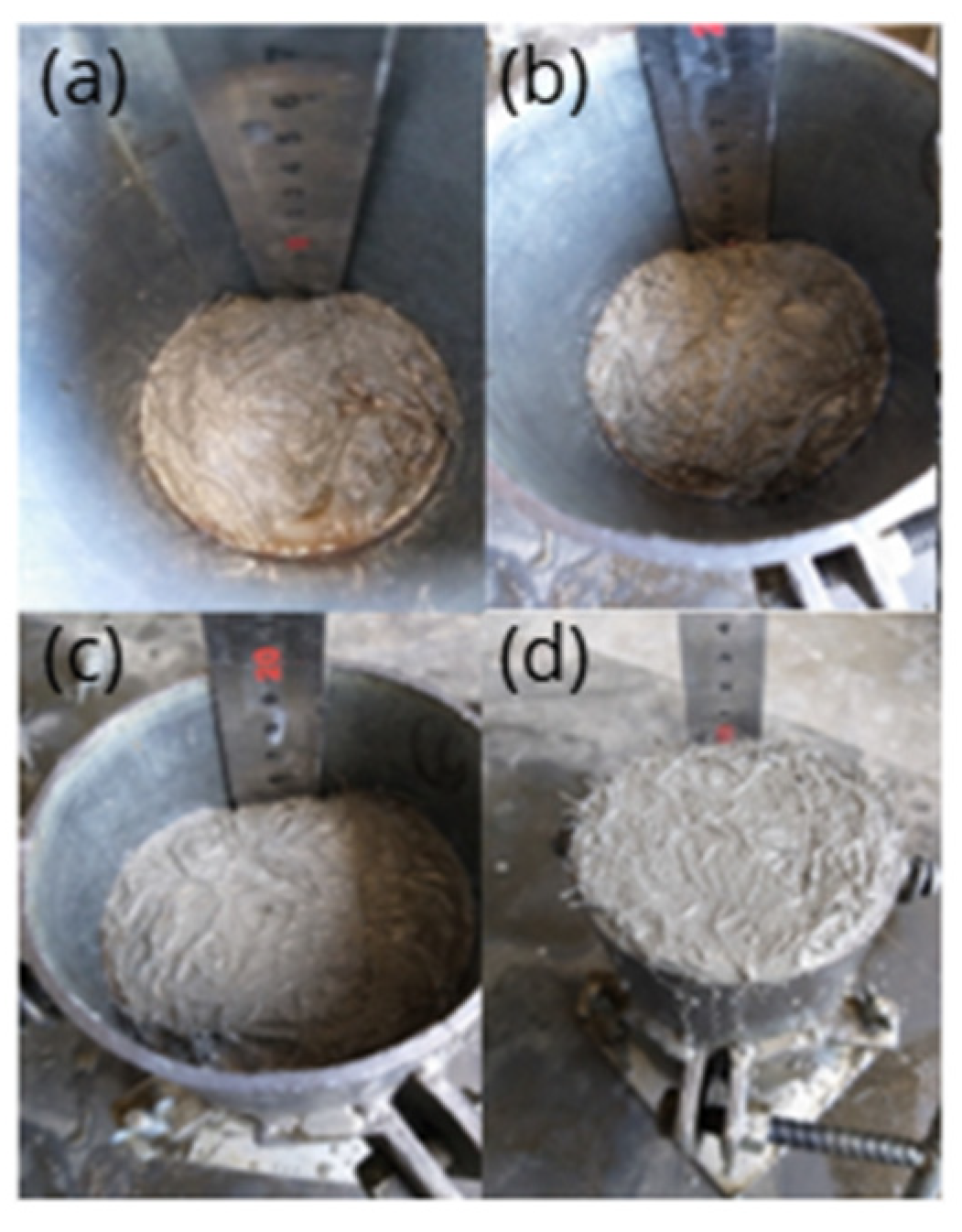
Cylindrical specimens 100 mm in diameter and 200 mm in height were used to evaluate the physical and mechanical properties of the concrete. To evaluate the properties of the composite under the conditions of use, impressions of the specimens were made in four layers of 50 mm, as shown in Figure 2. The permanent formwork produced with the composite material was developed with a thickness of 20 mm; thus, the short fibers (40 mm in length) were aligned in the longitudinal direction. Because the present research proposes the use of composites with plant fibers in the production of permanent formworks, it is important to verify whether the properties of this composite material are like those of the covering concrete used.

2.3. Physical and Mechanical Properties

The immersion water absorption and capillarity absorption tests were performed according to NBR 9778 [40] and NBR 9779 [41], respectively, whereas the axial compression and static modulus of elasticity tests were performed according to NBR 5739 [42] and NBR 8522 [43], respectively.
The axial compressive strength determination test was performed in a servo-controlled hydraulic press with a capacity of 1200 kN and stress increment rate of 0.45 MPa/s. The static modulus of elasticity determination test was performed using a Shimadzu servo-controlled universal testing machine with a capacity of 100 kN. All tests were performed at 28 d of age using three cylindrical specimens with a diameter of 100 mm and a height of 200 mm.
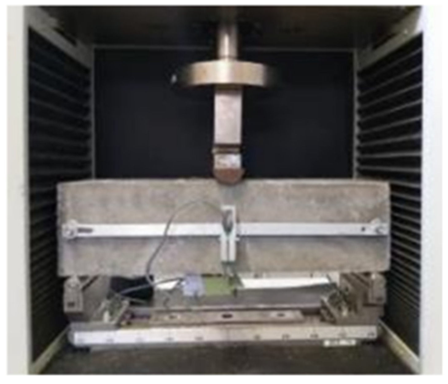
The flexure test of three notched prism points was performed at 28 days of age, with the aid of a Shimadzu servo-controlled universal testing machine at a displacement rate equal to 0.5 mm/s [44]. Three prismatic specimens (150 mm × 150 mm × 550 mm) containing a 25 mm deep notch on the underside were used (Figure 3). From the test results, the proportionality limit and residual stresses were determined using Equation (1) and Equation (2), respectively.
f R , i = 3 F R , i L 2 b h s p 2
f f c t , L = 3 F L L 2 b h s p 2
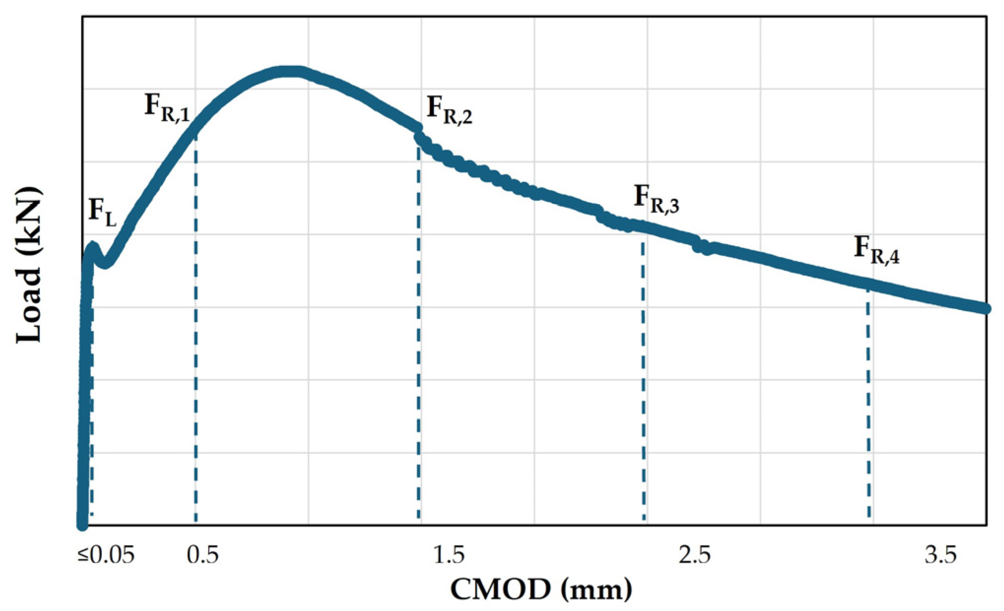
where ffct,L is the limit of proportionality; fR,i are the residual stresses (MPa); FL is equal to the highest value of the load up to a deflection of 0.05 mm; and FR,i are the loads relative to the crack openings (CMODj), as shown in Figure 4. L is the distance between supports (mm); b is the cross-sectional side (150 mm); and hsp is the usable height of the prism (125 mm).
The dynamic modulus of elasticity was determined by determining the ultrasonic pulse propagation velocity in three cylindrical specimens at 28 d of age, with a diameter of 100 mm and a height of 200 mm, according to NBR 15630 [45]. The Pundit Lab equipment from Proceq was used. The dynamic modulus of elasticity (Ed) was calculated by determining the wave propagation velocity (V) using Equation (3) and Equation (4), respectively.
E d = ρ V 2 K
K = 1 + v ( 1 2 v ) 1 v
where V is the speed of propagation of the wave (km/s), Ed is the dynamic modulus of elasticity (GPa), K is a coefficient determined by the Poisson coefficient (ν) (for concrete, it is equal to 0.2, so K is 0.9), and ρ is the apparent specific mass of the material in the hardened state (kg/m3).

2.4. Carbonation

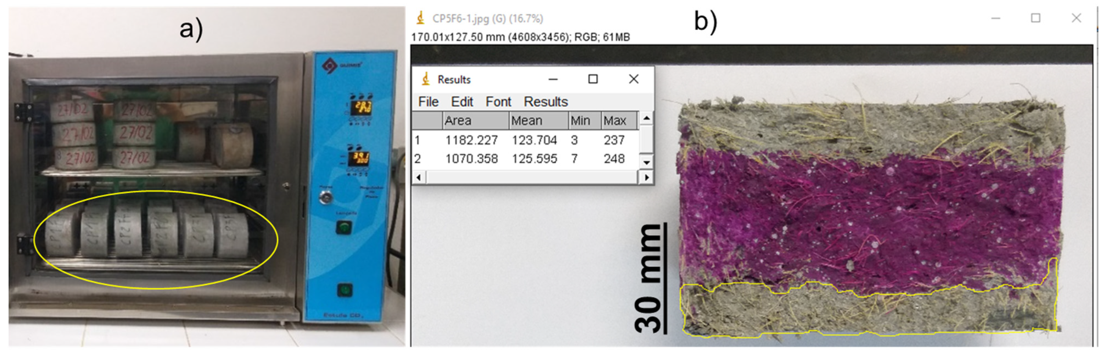
Three cylindrical specimens (100 mm diameter and 60 mm height) were used for the accelerated carbonation test. The test parameters followed ISO 1920 [46], using a QUIMIS carbonation chamber (Figure 5a) with a temperature control of (27 ± 2) °C, CO2 concentration of (3.0 ± 0.5) %, and a relative humidity of (65 ± 5) %. The carbonation depth was measured after 56, 63, and 70 days of exposure to CO2 by sprinkling phenolphthalein aqueous solution and analyzing the images obtained.
The images of the surfaces of the samples sprayed with phenolphthalein were analyzed with the aid of ImageJ 1.54r software (Figure 5b), estimating the carbonation depth (x), according to Equation (5).
x = K t 0.5
where t corresponds to the time of exposure to CO2 (days) and K refers to the accelerated diffusivity coefficient (mm*time−0.5).

3. Results and Discussions

3.1. Physical Properties

Table 4 presents the average values obtained for the physical properties of the composites and concrete along with their respective standard deviations. A comparative test of means using the Tukey method indicated a significant difference between the mean values obtained. The results are presented in Table 4 using letters, where equal letters for each property indicate statistically equal averages.
According to Table 4, the composites reinforced with plant fibers exhibited superior properties compared to those observed in the cementitious matrix. This superiority can be attributed to the high water absorption capacity of the fibers and the incorporation of air during the mixing and release processes of the composite. Other researchers reached similar conclusions regarding the influence of sisal fiber additions on the physical properties of composites [2,32]. Notably, these authors found that the addition of 2% fiber content resulted in a 19% reduction in water absorption by immersion and a 21% decrease in the void index compared to the reference matrix [2]. This behavior is attributed to the use of self-compacting matrices, which enable better homogenization of the composite, good workability (despite the addition of fibers), and low air incorporation, particularly with lower fiber contents.
Another critical factor influencing the results was the layer-wise molding of the composites (see Figure 2), which led to fiber alignment in the transverse direction of the specimen. This alignment effectively reduced the interconnection between the capillary channels along the height of the specimen, resulting in lower absorptivity for all composites compared to the matrix. Notably, the fibers utilized in this study underwent a hornification process, resulting in lower water absorption compared to natural fibers without any processing [27].
From the analysis of the results of the physical properties of composites with different fiber contents (F2, F4, and F6), presented in Table 4, it can be concluded that a beam manufactured with the same covering concrete (CC) will exhibit lower water absorption than a beam with a permanent formwork made from composites reinforced with sisal fibers at contents of 2%, 4%, and 6%. All evaluated physical parameters indicated higher compactness (higher density and lower void index) and a reduced likelihood of penetration by deleterious agents (lower absorption and sorptivity) in the CC than in the composites.
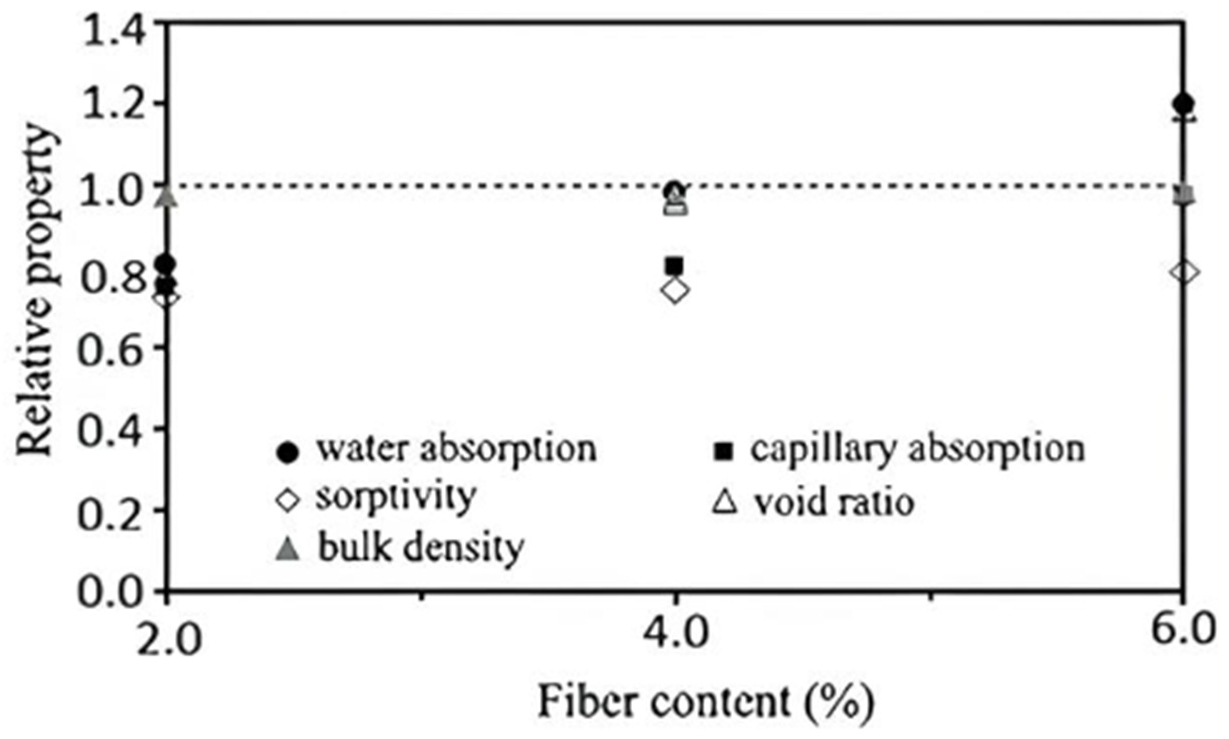
The molding procedure also demonstrated the ability to produce composites with 4% fiber content that exhibited physical properties comparable to those of the matrix. This capability opens the possibility of manufacturing a material that is not only tenacious, but also durable. Nevertheless, it is noteworthy that the increase in the fiber content directly influences the physical properties (water absorption, sorptivity, bulk density, capillary absorption and void ration) of the composite, as depicted in Figure 6.
In Figure 6, a pronounced increase in water absorption (by immersion or capillarity) and void index is evident with a 2–6% increase in fiber content. The porous nature of the fibers in the composites led to a higher water storage capacity within the material [31,47]. However, the molding process has a mitigating effect on the rate of water absorption by capillarity, resulting in a less intense increase in absorptivity with increasing fiber content. Table 4 indicates that the water absorption by capillarity was statistically similar in all mixtures. The matrix’s water absorption was approximately 28% higher than that of composites containing 2% fibers. For the composites with 4% and 6% fibers, no statistically significant variation in water absorption was observed. The specific masses were similar for all the composites.

3.2. Mechanical Properties

3.2.1. Axial Compressive Strength, Static Modulus of Elasticity and Three-Point Bending Tests

Table 5 summarizes the results for axial compressive strength, static modulus of elasticity, and three-point bending tests for the plain matrix (F0) and the cementitious composites reinforced with varying fiber contents (F2, F4, and F6). Additionally, the mechanical properties of the concrete cover (CC) were evaluated. The reported values represent the arithmetic means accompanied by their respective standard deviations. To evaluate the statistical significance of the results, Tukey’s test was performed, indicating significant differences between the mean values across the tested groups.
According to Table 5, the maximum reduction observed in the average values of the compressive strength (fc) of the composites is 17% with an increase in fiber content. This reduction in strength was comparatively lower than that reported by other researchers [2,28,29,30]. The use of a self-compacting matrix and molding method likely contributed to this outcome, enabling the production of composites (F2 and F4) with a void index statistically lower than that of the matrix (F0). On the other hand, the modulus of elasticity (E) demonstrated reductions of approximately 10%, 23%, and 30% with the introduction of 2%, 4%, and 6% fibers, respectively.
Compared to the concrete cover, the composite that closely approximated its mechanical properties was F2, showing a 40% reduction in the axial compressive strength and a 26% reduction in the modulus of elasticity. However, it is crucial to evaluate the mechanical behavior of cementitious materials under bending stress.
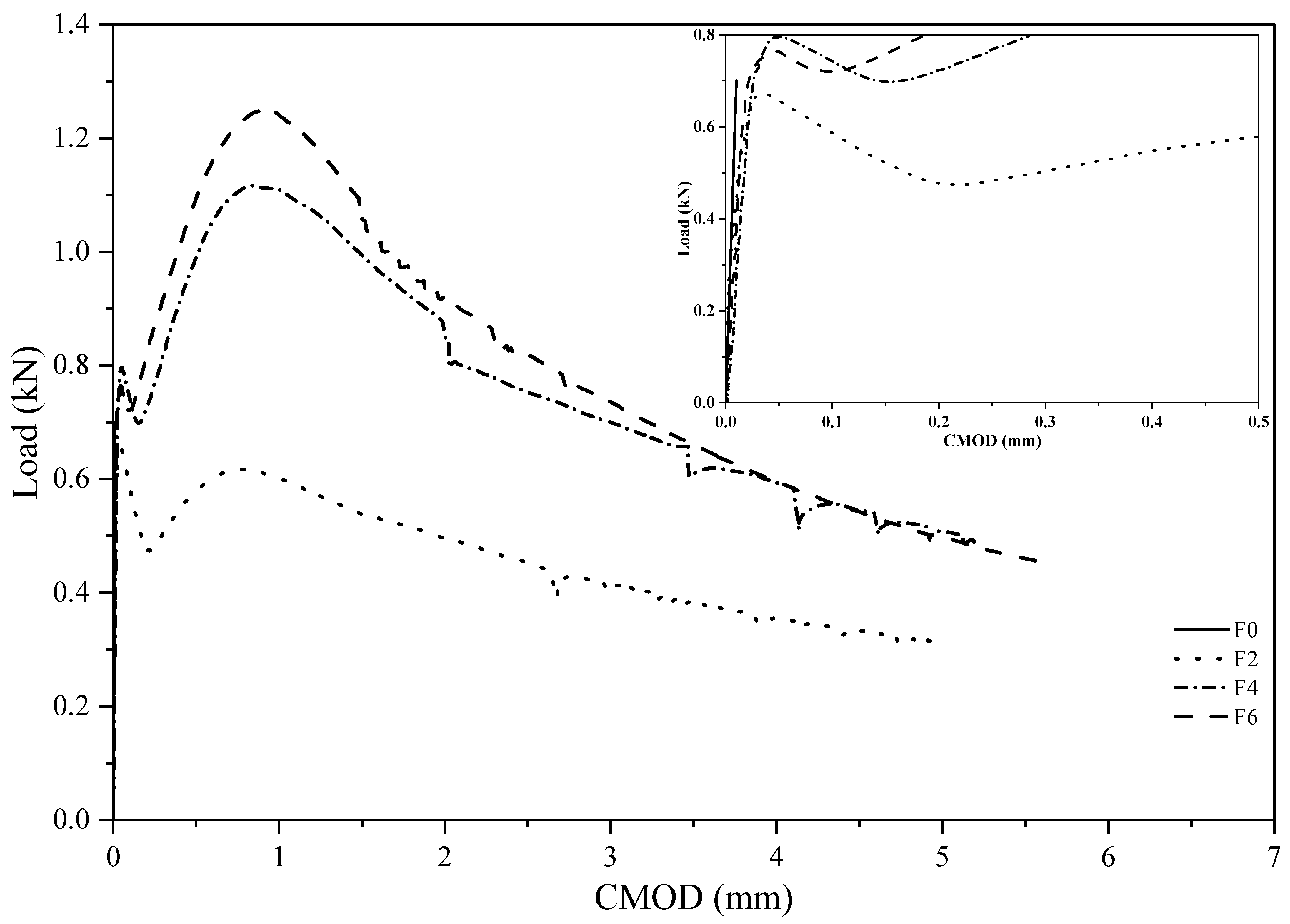
Figure 7 illustrates the outcomes of the notched beam bending test, showcasing load diagrams concerning crack opening (CMOD). Linear behavior was evident until the appearance of the first crack, where, for the matrix (F0), a brittle rupture occurred at a maximum load of 0.75 kN with a crack opening (CMOD) of approximately 0.02 mm. In the composites, the linear elastic zone before the first crack is influenced by the matrix; however, the post-crack behavior differs because the fibers can transfer stress between the crack faces. This characteristic makes the post-crack behavior less brittle because the fibers contribute to stress transfer until the process of total pullout or rupture of the fibers occurs [48].
The composite with 2% fibers exhibited a significant reduction in the load after the first crack, indicating that the percentage of fibers crossing the crack was insufficient to transfer the entire applied load. Although load recovery occurs when the fibers are engaged, the residual stress values, as shown in Table 5, remain below the limit of proportionality, reflecting a behavior known as deflection softening [28,29].
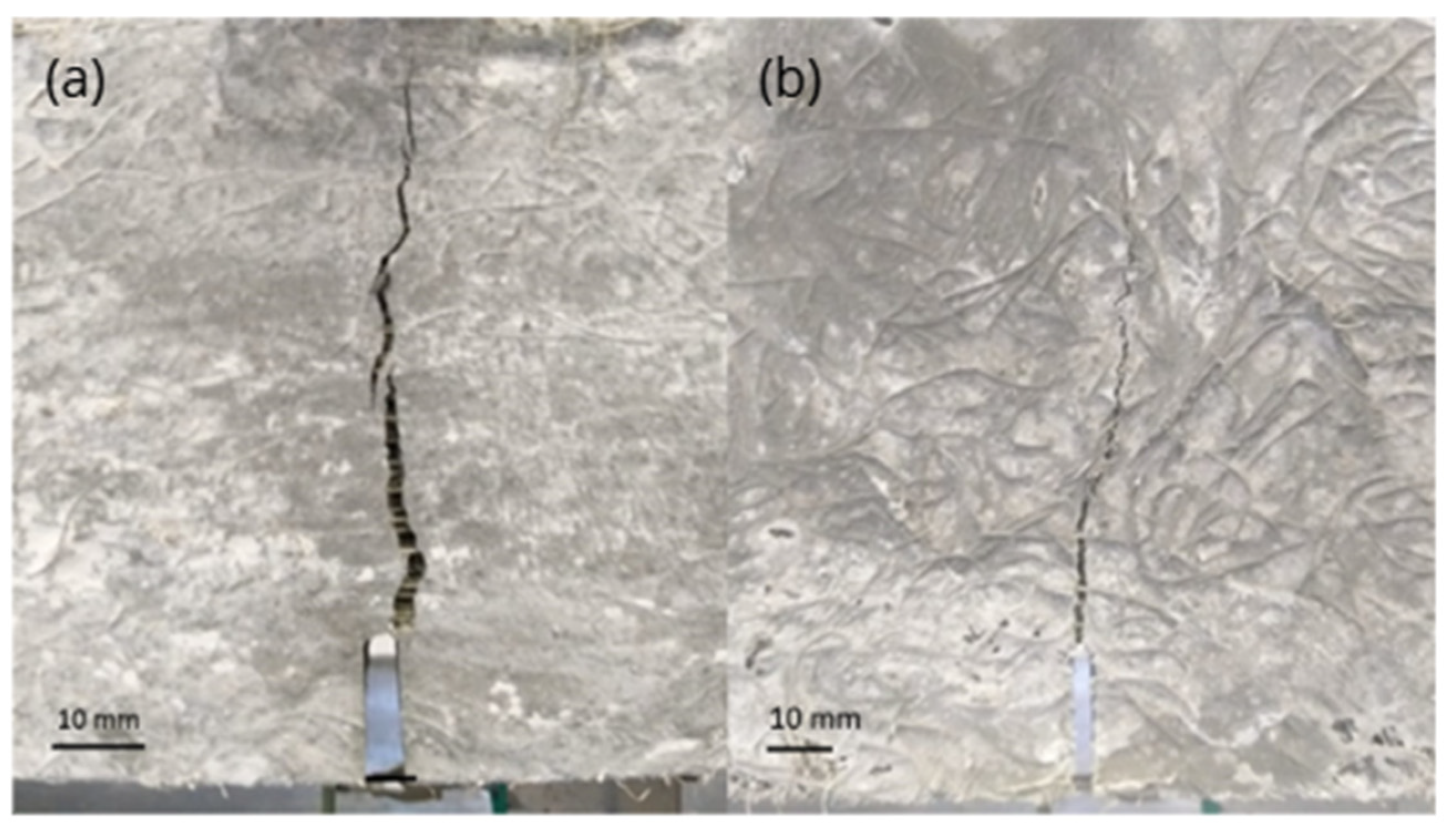
In contrast, composites with 4% and 6% fibers exhibited a different behavior characterized by an increase in the resistance load after the first crack, known as deflection hardening (Figure 7). During this post-cracking period, the load resisted by the composite surpassed the load required to break (peak) the matrix [2]. Beyond the increase in flexural strength, higher fiber content contributed to better crack control in the composites. Figure 8 illustrates the cracking behavior of the composites with 2% fibers (F2) and 6% fibers (F6) during the test (CMOD = 5 mm). It is evident that a higher fiber content limits the opening of the crack propagating from the notch.
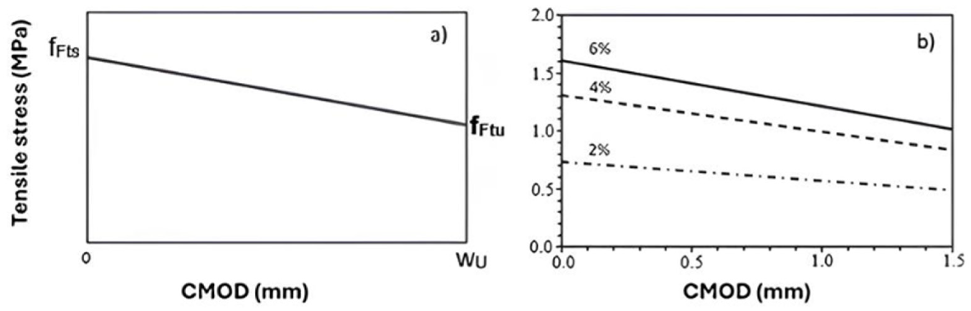
From the results of the notched prism bending test, it was possible to determine the stress versus crack opening diagram under direct tension, defined by the post-cracking behavior of fiber-reinforced concrete (FRC), which must be applied in the design of these elements in the Ultimate Limit State [49]. The Linear Model, shown in Figure 9a, uses two reference values obtained using Equations (6) and (7).
f F t s = 0.45 f R 1
f F t u = f F t s w u C M O D 3 f F t s 0.5 f R 3 + 0.2 f R 1
where fFts represents the post-service cracking residual direct tensile strength of the fiber-reinforced composite (MPa), fFtu represents the post-ultimate post-cracking residual direct tensile strength of the fiber-reinforced composite (MPa), and wu is the maximum crack opening considered in the design, expressed in millimeters.
When considering a crack opening limit of 1.5 mm to minimize the impact of external agents on concrete and reinforcement in reinforced concrete elements protected by a composite permanent formwork, the data from Table 5 can be used to derive post-cracking constitutive laws for sisal fiber composites, as illustrated in Figure 9b. Under tension, linear behavior characterized by deflection softening was observed for all composites, with a higher fiber content resulting in higher stress. The calculated fFts values were 0.8 MPa, 1.3 MPa, and 1.6 MPa for reinforced composites with fiber contents of 2%, 4%, and 6%, respectively, while the respective fFtu values were 0.5 MPa, 0.8 MPa, and 1.0 MPa.

3.2.2. Ultrasonic Pulse Velocity and Dynamic Modulus of Elasticity

Table 6 shows the results of the ultrasonic pulse velocity and dynamic modulus of elasticity obtained from the propagation test of ultrasonic waves in the matrix (F0) and composites reinforced with sisal fibers (F2, F4, and F6).
There was a slight reduction in the ultrasonic pulse velocity (V) with an increase in the vegetable fiber content. According to Ashrafian et al. [50], the ultrasonic pulse velocity in fiber-reinforced concrete is influenced by two primary factors: the material density and void content. In homogeneous materials, ultrasonic pulse velocity is typically a function of the modulus of elasticity, Poisson’s ratio, and material density. However, in heterogeneous materials, such as concrete with fibers, the ultrasonic pulse intensity can be influenced by the presence of discontinuities, such as aggregate grains, fibers, voids, or microcracks.
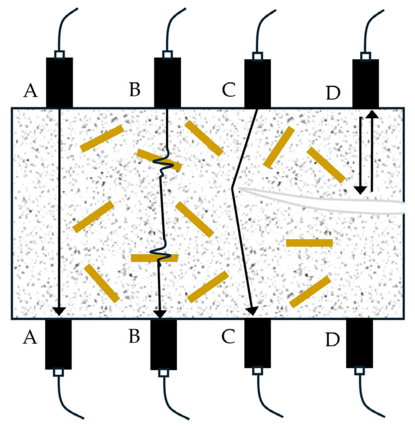
Figure 10 illustrates the various internal conditions encountered during ultrasonic pulse testing according to ACI 228.2R [51]. The AA line represents the shortest path for homogeneous material. The second case (BB line) depicts the pulse passing through regions with different densities, such as an aggregate or fiber. In the CC line, the trajectory is modified by the deviation around the edge of a pore or tip of a fissure. In the latter cases, the time taken by the pulse to traverse the sample is longer than that in the first situation. In the fourth situation (DD), the passage of the pulse is interrupted by a void (fissure or large pores). Based on this concept, the British standard BS EN12504-4 [52] establishes concrete quality standards based on ultrasonic pulse speed, ranging from very weak (v < 2.0 km/s) to excellent (v > 4.5 km/s).
In the composites produced in this study, an increase in the specific mass and void index was observed (Table 4), owing to the higher fiber content. Consequently, there was a reduction in the ultrasonic pulse velocity values (Table 6), owing to the introduction of a greater number of defects in the material. This reduction in ultrasonic pulse speed due to an increase in flax plant fiber content aligns with the findings of Page et al. [53], who linked the phenomenon to the appearance of internal defects. These defects resulted from the alignment of the fibers during specimen preparation, leading to the formation of fiber agglomerates within the matrix. In concrete reinforced with manufactured fibers, there was an observed increase in porosity and a subsequent reduction in the ultrasonic pulse speed [50].
Despite the reduction in speed values, all the produced composites exhibited good quality, as per the British standard BS EN12504-4 [52]. This suggests that the introduction of fibers did not result in significant damage to the material.
The ultrasonic pulse velocity in cement-based materials depends on the modulus of elasticity, which in turn is directly correlated with compressive strength. Therefore, it is anticipated that a relationship exists between the ultrasonic pulse velocity and compressive strength of the composites, allowing the ultrasonic pulse test to be a potential estimator of this mechanical property. Numerous correlation equations have been proposed for this purpose, the most common of which is an exponential function represented by Equation (8) [54].
f c = a e b     V
where fc is the compressive strength and V is the ultrasonic pulse speed. The coefficients “a” and “b” were obtained from experimental results. For simple concrete, from the results of other researchers, the values of “a” are equal to 1.146 and 1.190, and the values of “b” are equal to 0.770 and 0.715 [54].
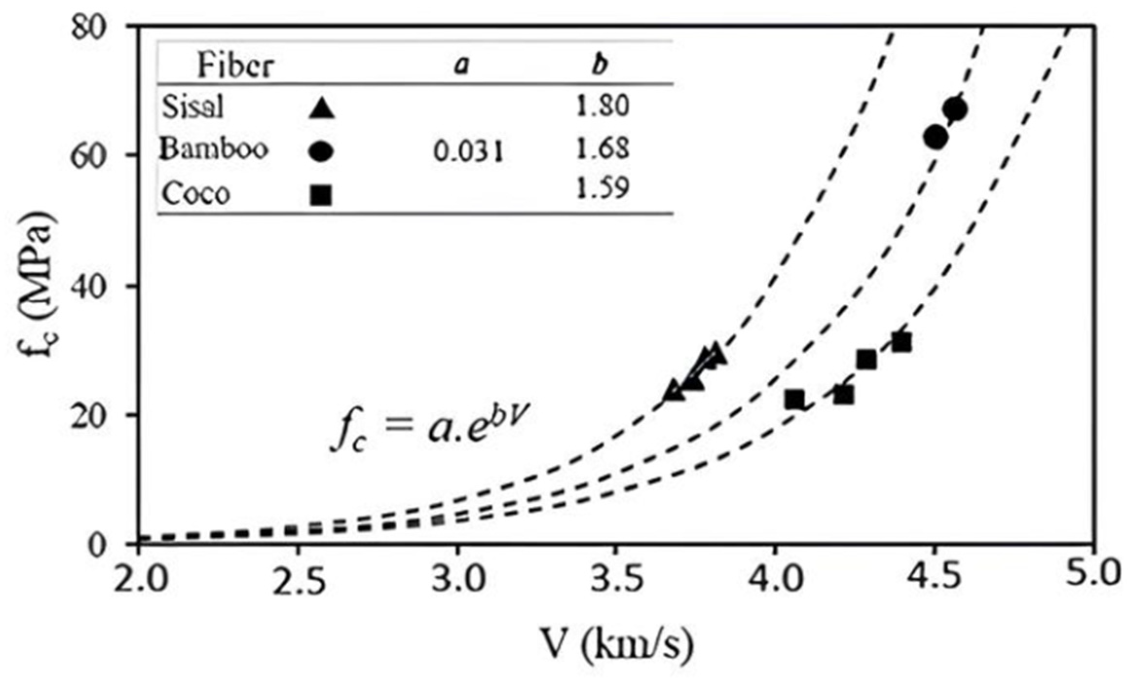
Using the experimental results obtained in this study for sisal-fiber-reinforced composites, together with data reported by [55] for coconut fiber composites and [56] for bamboo fiber composites, the relationship between compressive strength and ultrasonic pulse velocity can be fitted using Equation (8). Coefficient a shows similar values for all fiber types, while coefficient b ranges from 1.59 to 1.80. The fitted relationship is presented in Figure 11.
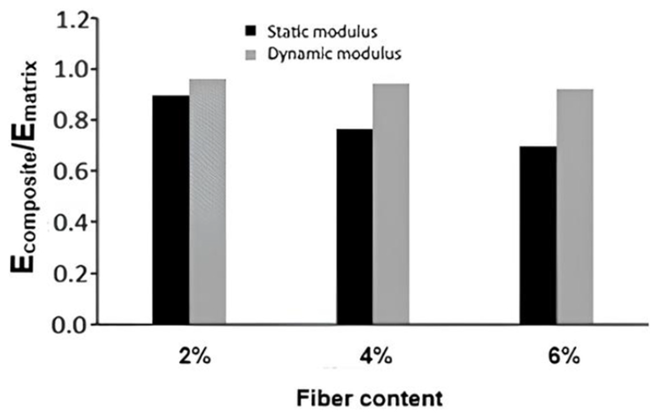
The results revealed a decrease in the compressive strength and dynamic modulus of elasticity, accompanied by a reduction in the ultrasonic pulse velocity. This reduction is directly proportional to the increase in the sisal fiber content of the composites, as illustrated in Table 6. Despite efforts to establish a correlation between the dynamic modulus of elasticity (Table 6) and static modulus of elasticity (Table 5) of cement-based materials, it is apparent that the absolute values differ for the studied composites. Consequently, the variation in these properties and the increase in the fiber content cannot be correlated, as shown in Figure 12, which presents the modulus of elasticity of the composite (Ecomposite) to the matrix (Ematrix) ratio as a function of fiber content. While the dynamic modulus of elasticity exhibited only an 8% reduction relative to the matrix with the introduction of 6% fibers, the static modulus of elasticity experienced a more substantial reduction of 30% for the same fiber content.

3.3. Carbonation Analysis

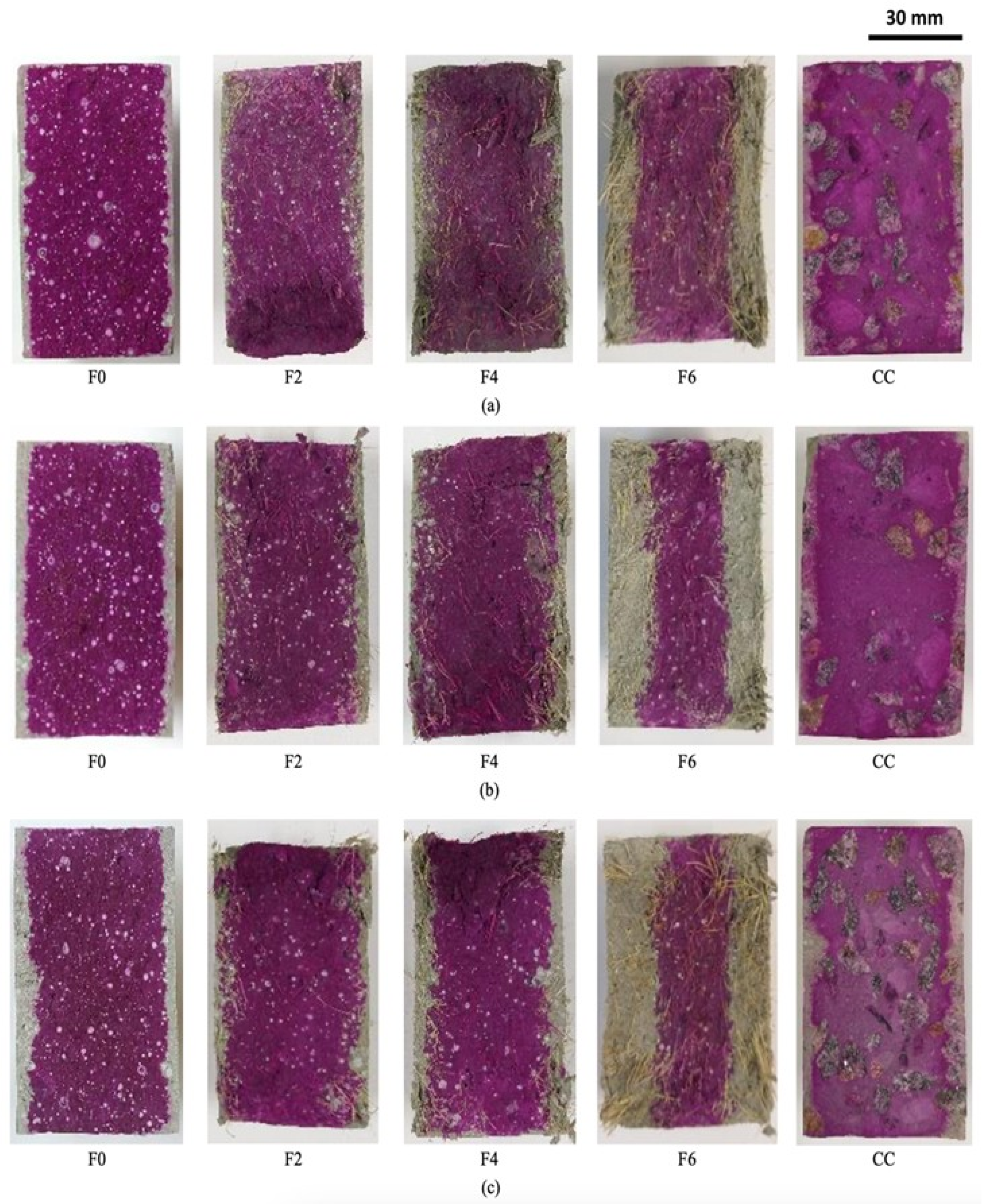
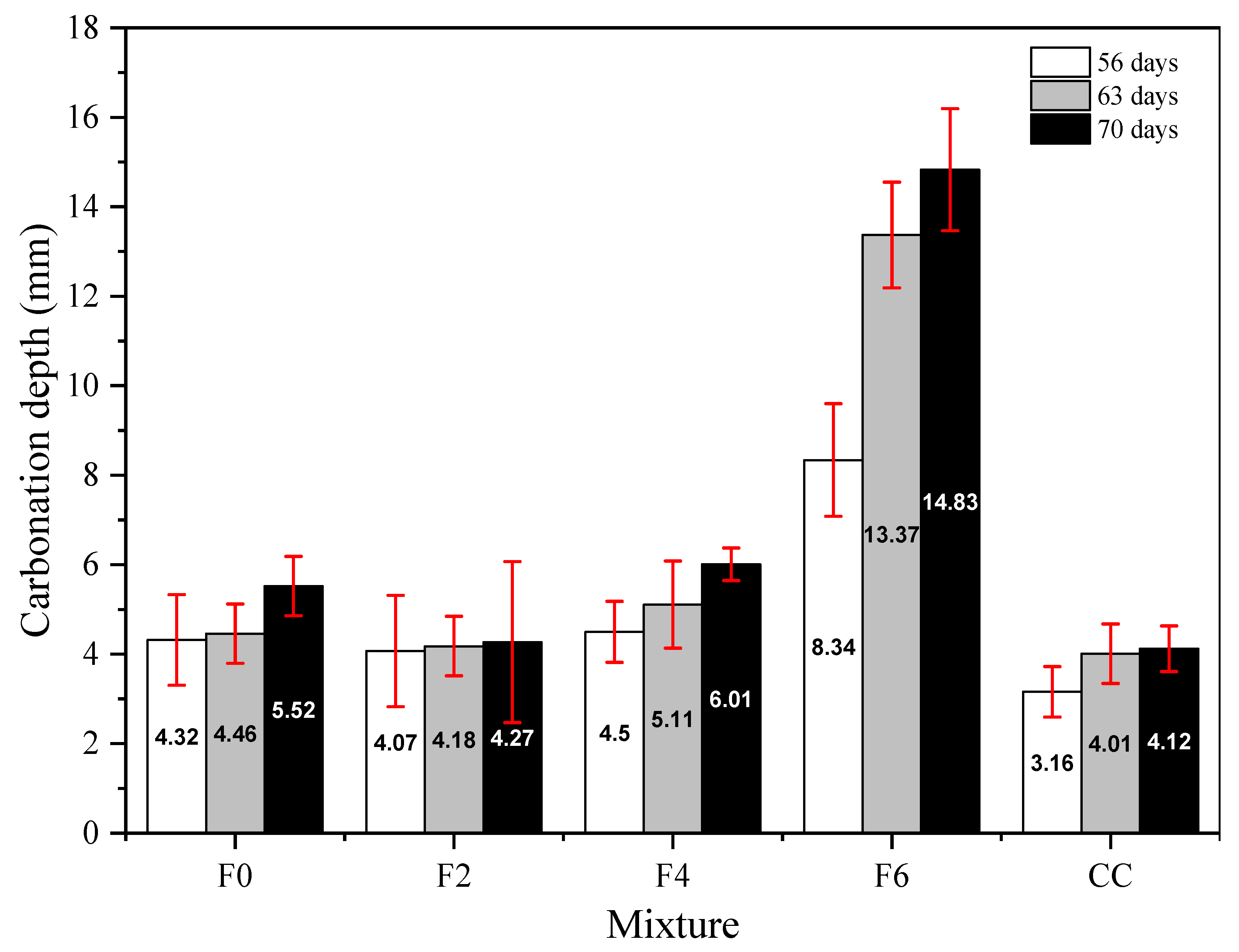
As outlined in the methodology, the assessment of carbonation depth involved aqueous–alcoholic spraying of phenolphthalein on the fractured surface of the specimens. The results, depicted in Figure 13, are further detailed in Table 7 and Figure 14, illustrating the average carbonate areas and depths after 56, 63, and 70 d of accelerated carbonation.
After 70 days of exposure, it was observed that across the composites, the average carbonate area and carbonation depth increased with the increase in fiber content, excluding the F2 composite, which displayed a 22.80% reduction compared to the reference matrix (F0). Specifically, the carbonated areas increased by 8.6% and 168.48% for composites with 4% and 6% fibers, respectively. In comparison to the concrete cover (CC), composites containing fibers exhibited the following increases in carbonate area after 70 days of exposure: 3.54% (F2), 45.84% (F4), and 260.06% (F6).
The elevation in carbonate regions within the fiber-reinforced composites can be attributed to the high water absorption capacity of the sisal fibers and incorporation of air during the mixing process. These factors contribute to an overall increase in the total porosity of the composite and consequently enhance the diffusion of CO2. A previous study [9] indicated that, owing to the hydrophilic nature and pronounced porosity of plant fibers, composites containing them exhibit a heightened ability to encapsulate carbon dioxide. This phenomenon not only preserves the integrity of the fibers, but also prevents their degradation in an alkaline environment, thereby maintaining the overall integrity of the composite.
The carbonation results obtained in this study were consistent with the observations made by Hu et al. [32] and Pavithra et al. [33], who also noted an increase in the carbonate layer due to the presence of plant fibers. These researchers concluded that the advancement of carbonation is facilitated by the resulting microstructures and physical properties of these materials. The heightened porosity at the fiber/cementitious matrix interface, as illustrated in Figure 14, promoted the passage of CO2, contributing to the observed increase in the carbonate layer.
The progression of the carbonate front, attributed to the elevated fiber content in the composites, underscores the feasibility of utilizing these materials as permanent formworks. This phenomenon holds promise for mitigating the long-term degradation of plant fibers, primarily because of the alkalinity of the matrix, which can reduce the mechanical strength of the composite. Another mechanism of degradation involves mineralization of the lumen of the sisal fibers, driven by the migration of free calcium hydroxides. As noted by Amaral et al. [27], natural fibers establish a porous network that facilitates moisture distribution in the cementitious matrix. This, in turn, promotes delayed hydration reactions, allowing for crack control, carbonation reactions, and an overall improvement in the bearing capacity of the composites.
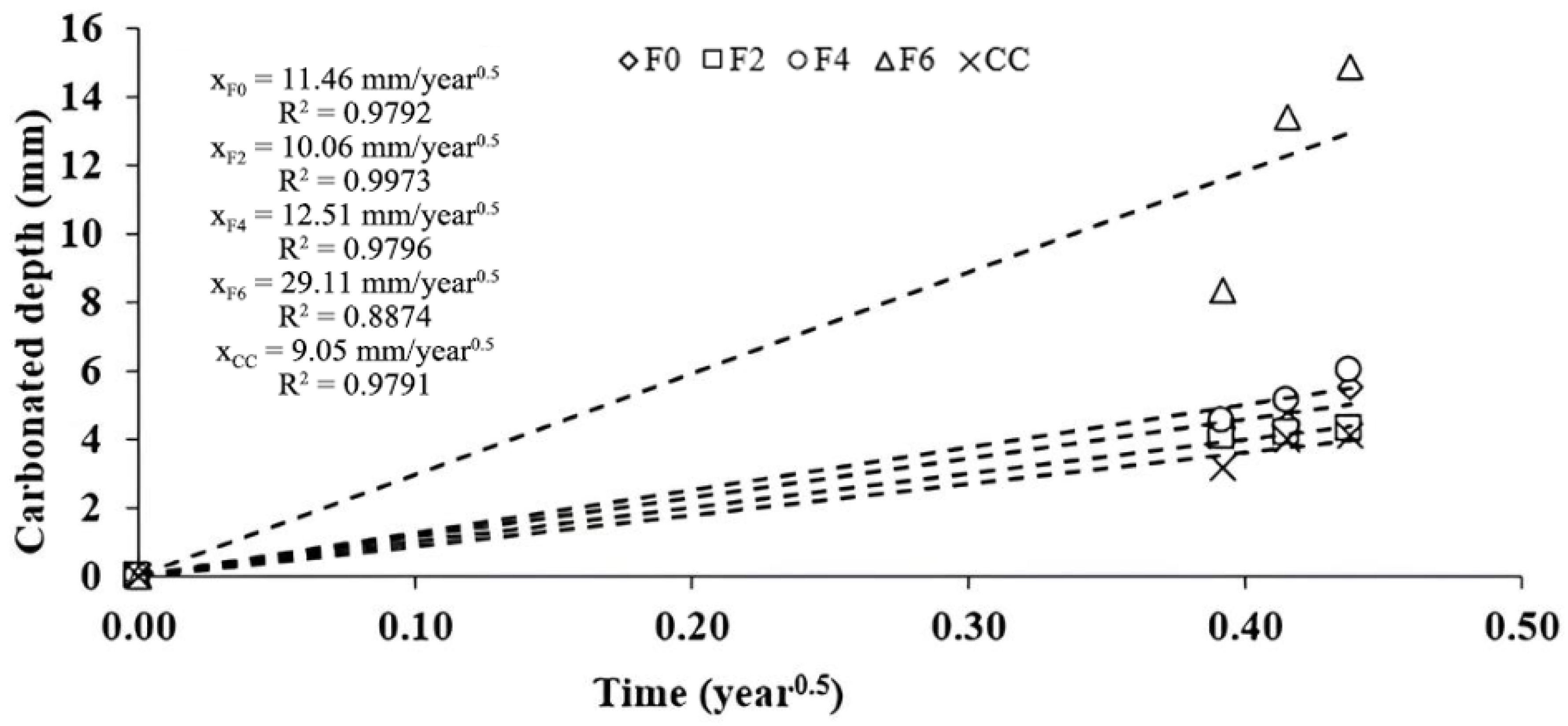
The carbonation depth results presented in Figure 15 are related to the time to calculate the accelerated carbonation coefficient (Kacel), obtained by means of the mathematical model presented in Equation (5). The correlation curves are shown in Figure 15.
The concrete cover (CC) exhibited a lower accelerated carbonation coefficient (9.05 mm/year0.5) compared to the composites, where the carbonation rate increased with higher fiber content. The reference composite (F0) and those containing 2% (F2) and 4% (F4) of fibers demonstrated similar Kacel values, measuring 11.46 mm/year0.5, 10.06 mm/year0.5, and 12.51 mm/year0.5, respectively. However, the composite with 6% fibers (F6) showed significantly poorer performance than the others, with a Kacel value of 29.11 mm/year0.5.
While analyzing accelerated carbonation coefficients provides valuable insights into material quality, establishing correlation indices (x′) between carbonation coefficients determined by accelerated tests (Kacel) and those under natural conditions (Knat) of exposure, as per Equation (9), adds another layer of meaningful information.
x = K a c e l K n a t
However, studies of this nature are infrequent in the literature, primarily because of the extensive duration of the tests. Ribeiro et al. [57] conducted an extensive review and compiled data from various studies conducted worldwide, resulting in 117 correlation indices (x′). By leveraging this analysis and considering the classification of natural environments proposed by Gao et al. [58], which is based on the CO2 concentration values, Ribeiro et al. [57] introduced the correlation indices listed in Table 8.
Utilizing the correlation indices outlined in Table 8, estimates were made for the natural carbonation coefficients (Knat) and anticipated shelf life, assuming a covering thickness of 30 mm. The results, as presented in Table 9, highlight that concrete, when used as a cover, exhibits a greater capacity to protect reinforcement against carbonation than structures incorporating fiber-reinforced composites as part of the protective layer. Considering the prescribed minimum design life of 50 years [59] and a minimum thickness of 30 mm in environments with a moderate aggressiveness class [60], it is evident that all composites surpass the limits stipulated by Brazilian standards.

4. Conclusions

This study demonstrates the technical feasibility of using sisal-fiber-reinforced cement composites as permanent formworks, offering a sustainable alternative to conventional concrete cover. The tests performed are limited to standard specimens containing the material proposed as the permanent formwork. The composite with 2% fiber content (F2) exhibited the lowest porosity and mechanical properties closest to conventional concrete cover, making it suitable for structural elements subjected to axial loads, such as columns. In contrast, the 6% fiber composite (F6) showed better performance for beam formwork due to its improved stress transfer and crack control under bending.
Composites containing 2% and 4% fibers showed the best durability performance, ensuring a service life exceeding 50 years even in severe industrial environments. Although higher fiber contents increase porosity and CO2 diffusion, the F2 composite reduced the carbonated area by 22.8% compared with the reference matrix. Carbonation may also contribute to the preservation of natural fibers by reducing matrix alkalinity, thereby limiting alkaline degradation.
Despite higher carbonation rates observed for composites with 4% and 6% fibers, formulations F2 and F4 maintained adequate durability. The F6 composite, however, showed a higher carbonation rate and did not meet durability requirements in several scenarios. Overall, sisal–cement composites, particularly F2 and F4, represent sustainable and technically viable materials for permanent formwork applications in reinforced concrete structures.
It is important to highlight that the carbonation analysis of this study is based mainly on accelerated testing, using generalized correlation coefficients that are not yet sufficiently validated for sisal fiber composites. Further studies should still be conducted to more accurately evaluate the long-term durability of structures containing this material.

Author Contributions

I.M.d.S.P.: data curation, formal analysis, investigation, methodology, validation, visualization, writing—original draft, and writing—review and editing. R.C.d.A.M.: methodology, resources, supervision, and writing—review. D.V.R.: methodology and writing—review and editing. P.R.L.L.: data curation, formal analysis, methodology, validation, writing—original draft and writing—review and editing. All authors have read and agreed to the published version of the manuscript.

Funding

The authors acknowledge the financial support provided by the Foundation for Research Support of the State of Bahia (FAPESB), grant BOL0403/2018 and No. 20/2025; the Brazilian Federal Agency for Support and Evaluation of Graduate Education (CAPES)—Finance Code 001; the National Council for Scientific and Technological Development (CNPq), grant No. 304631/2022-1; and the State University of Santa Cruz (UESC) through the research project SEI No. 073.17253.2024.0029516-15.

Data Availability Statement

The original contributions presented in the study are included in the article; further inquiries can be directed to the corresponding author.

Conflicts of Interest

The authors declare no conflicts of interest.

References

  1. Basdeki, M.; Apostolopoulos, C. Mechanical Behavior Evaluation of Tempcore and Hybrid Reinforcing Steel Bars via a Proposed Fatigue Damage Index in Long Terms. Metals 2021, 11, 834. [Google Scholar] [CrossRef]
  2. Lima, P.R.L.; Barros, J.A.O.; Roque, A.B.; Fontes, C.M.A.; Lima, J.M.F. Short Sisal Fiber Reinforced Recycled Concrete Block for One-Way Precast Concrete Slabs. Constr. Build. Mater. 2018, 187, 620–634. [Google Scholar] [CrossRef]
  3. Mei, Z.; Xu, M.; Luo, S.; Tan, Y.; Li, H. Concrete Formwork Reuse in a Supply Chain with Dynamic Changes Using ABMS and Discrete Events. J. Clean. Prod. 2022, 332, 130038. [Google Scholar] [CrossRef]
  4. Li, W.; Lin, X.; Bao, D.W.; Xie, Y.M. A Review of Formwork Systems for Modern Concrete Construction. Structures 2022, 38, 52–63. [Google Scholar] [CrossRef]
  5. Wang, Z.; Liang, X.; Wang, Y.; Zhai, T. Experimental and Theoretical Investigations on the Flexural Behavior of RC Slabs with Steel-PVA Hybrid Fiber Reinforced Cementitious Composite (HFRCC) Permanent Formwork. Case Stud. Constr. Mater. 2022, 17, e01432. [Google Scholar] [CrossRef]
  6. Sikder, K.K. Ferrocement as Permanent Formwork for Reinforced Concrete Columns. Master’s Thesis, Bangladesh University of Engineering and Technology, Dhaka, Bangladesh, 1996. Available online: http://lib.buet.ac.bd:8080/xmlui/handle/123456789/923 (accessed on 17 November 2025).
  7. Romarate, R.B.; Mostrales, D.S. Cast in place permanent ferrocement formwork for concrete beams and columns. Int. J. Recent Res. Asp. 2015, 2, 33–37. [Google Scholar]
  8. Behera, G.C.; Rao, T.D.G.; Rao, C.B.K. Torsional behaviour of reinforced concrete beams with ferrocement U-jacketing—Experimental study. Case Stud. Constr. Mater. 2016, 4, 15–31. [Google Scholar] [CrossRef]
  9. Tawab, A.A.; Fahmy, E.H.; Shaheen, Y.B. Use of permanent ferrocement forms for concrete beam construction. Mater. Struct. 2012, 45, 1319–1329. [Google Scholar] [CrossRef]
  10. Mansur, M.A.; Maalej, M.; Ismail, M. Study on corrosion durability of ferrocement. ACI Mater. J. 2008, 105, 28–35. [Google Scholar] [CrossRef]
  11. Shannag, M.J.; Mourad, S.M. Flowable high strength cementitious matrices for ferrocement applications. Constr. Build. Mater. 2012, 36, 933–939. [Google Scholar] [CrossRef]
  12. Kim, H.Y.; Koh, K.T.; You, Y.J.; Ryu, G.S.; Seo, D.W.; Jin, S.S.; Nam, J.H. Load-deflection behaviour of concrete slab-type elements casted on stay-in-place TRC formwork. Compos. Struct. 2020, 244, 112310. [Google Scholar] [CrossRef]
  13. Li, Q.H.; Yin, X.; Huang, B.T.; Luo, A.M.; Lyu, Y.; Sun, C.J.; Xu, S.L. Shear interfacial fracture of strain-hardening fiber-reinforced cementitious composites and concrete: A novel approach. Eng. Fract. Mech. 2021, 253, 107849. [Google Scholar] [CrossRef]
  14. Huang, B.T.; Li, Q.H.; Xu, S.L.; Li, C.F. Development of reinforced ultra-high toughness cementitious composite permanent formwork: Experimental study and digital image correlation analysis. Compos. Struct. 2017, 180, 892–903. [Google Scholar] [CrossRef]
  15. Leung, C.K.; Cao, Q. Development of pseudo-ductile permanent formwork for durable concrete structures. Mater. Struct. 2010, 43, 993–1007. [Google Scholar] [CrossRef]
  16. Kim, G.B.; Pilakoutas, K.; Waldron, P. Thin FRP/GFRC structural elements. Cem. Concr. Compos. 2008, 30, 122–137. [Google Scholar] [CrossRef]
  17. Kumar, P.P.; Kumar, H.R.; Sai, P.; Jaketia, A.; Achha, A.; Soni, L. A Study on Durability of Sisal Fibre Reinforced Concrete Composites. Int. J. Emerg. Technol. Adv. Eng. 2017, 7, 272–281. [Google Scholar]
  18. Li, M.; Khelifa, M.; Khennane, A.; El Ganaoui, M. Structural response of cement-bonded wood composite panels as permanent formwork. Compos. Struct. 2019, 209, 13–22. [Google Scholar] [CrossRef]
  19. Schafer, H.G.; Brunssen, G.W. Sisal fibre reinforced lost form work for floor slabs. In Proceedings of the Second International Symposium on Vegetable Plants and Their Fibers as Building Materials, Salvador, Brazil, 17–21 September 1990; Chapman and Hall: London, UK, 1990; pp. 162–174. [Google Scholar]
  20. Arruda Filho, A.B.d.; Lima, P.R.L.; Carvalho, R.F.; Gomes, O.d.F.M.; Filho, R.D.T. Effect of Number of Layers on Tensile and Flexural Behavior of Cementitious Composites Reinforced with a New Sisal Fabric. Textiles 2024, 4, 40–56. [Google Scholar] [CrossRef]
  21. Yooprasertchai, E.; Wiwatrojanagul, P.; Pimanmas, A. A Use of Natural Sisal and Jute Fiber Composites for Seismic Retrofitting of Nonductile Rectangular Reinforced Concrete Columns. J. Build. Eng. 2022, 52, 104521. [Google Scholar] [CrossRef]
  22. Li, Z.; Guo, T.; Chen, Y.; Yang, W.; Wang, J.; Jin, L. Preparation and Properties of Pretreated Jute Fiber Cement-Based Composites. Ind. Crops Prod. 2024, 210, 118090. [Google Scholar] [CrossRef]
  23. Lima, P.R.L.; Barros, J.A.O.; Santos, D.J.; Fontes, C.M.; Lima, J.M.F.; Toledo Filho, R. Experimental and Numerical Analysis of Short Sisal Fiber-Cement Composites Produced with Recycled Matrix. Eur. J. Environ. Civ. Eng. 2019, 23, 70–84. [Google Scholar] [CrossRef]
  24. Ferreira, S.R.; Silva, F.d.A.; Lima, P.R.L.; Toledo Filho, R.D. Effect of Hornification on the Structure, Tensile Behavior and Fiber Matrix Bond of Sisal, Jute and Curauá Fiber Cement Based Composite Systems. Constr. Build. Mater. 2017, 139, 551–561. [Google Scholar] [CrossRef]
  25. Lima, P.R.L.; Santos, M.; Camilloto, P.; Souza Cruz, R. Effect of Surface Biopolymeric Treatment on Sisal Fiber Properties and Fiber-Cement Bond. J. Eng. Fibers Fabr. 2017, 12, 2. [Google Scholar] [CrossRef]
  26. Schutz, G.F.; de Ávila Gonçalves, S.; Alves, R.M.V.; Vieira, R.P. A Review of Starch-Based Biocomposites Reinforced with Plant Fibers. Int. J. Biol. Macromol. 2024, 261, 129916. [Google Scholar] [CrossRef]
  27. do Amaral, L.M.; Rodrigues, C.d.S.; Poggiali, F.S.J. Hornification on Vegetable Fibers to Improve Fiber-Cement Composites: A Critical Review. J. Build. Eng. 2022, 48, 103947. [Google Scholar] [CrossRef]
  28. Ren, G.; Yao, B.; Huang, H.; Gao, X. Influence of Sisal Fibers on the Mechanical Performance of Ultra-High Performance Concretes. Constr. Build. Mater. 2021, 286, 122958. [Google Scholar] [CrossRef]
  29. Jamshaid, H.; Mishra, R.K.; Raza, A.; Hussain, U.; Rahman, M.L.; Nazari, S.; Chandan, V.; Muller, M.; Choteborsky, R. Natural Cellulosic Fiber Reinforced Concrete: Influence of Fiber Type and Loading Percentage on Mechanical and Water Absorption Performance. Materials 2022, 15, 874. [Google Scholar] [CrossRef]
  30. Amjad, H.; Arsalan Khushnood, R.; Ali Memon, S. Biomimetic Robust Self-Healing of Bacillus Subtilis Immobilized through Sisal Fiber for next-Generation Concrete Infrastructure. Constr. Build. Mater. 2023, 368, 130299. [Google Scholar] [CrossRef]
  31. Thomas, B.C.; Jose, Y.S. A Study on Characteristics of Sisal Fiber and Its Performance in Fiber Reinforced Concrete. Mater. Today Proc. 2022, 51, 1238–1242. [Google Scholar] [CrossRef]
  32. Hu, W.H.; Zhang, D.; Ftwi, E.; Ellis, B.R.; Li, V.C. Development of Sustainable Low Carbon Engineered Cementitious Composites with Waste Polyethylene Fiber, Sisal Fiber and Carbonation Curing. Resour. Conserv. Recycl. 2023, 197, 107096. [Google Scholar] [CrossRef]
  33. Pavithra, K.; Shewale, M.; Asalkar, S.; Shinde, N.; Korke, P.; Balaji, A.; Gobinath, R.; Anuradha, R. Studies on Usage of Natural Fibers and Eco Sand for Sustainable Concreting. Mater. Today Proc. 2022, 49, 1689–1693. [Google Scholar] [CrossRef]
  34. Soares, E.N.C.; Garcia, D.C.d.S.; Martins, M.A.; Júnior, J.B.G. Interfacial Behavior and Mechanical and Microstructural Properties of Cement-Based Composites Reinforced with Banana, Eucalyptus and Sisal Fibers. Constr. Build. Mater. 2026, 507, 145075. [Google Scholar] [CrossRef]
  35. Zhao, L.; Ding, Y.; Li, S.; Song, Y.; Gong, H.; Zhang, Y. Silane Treatment for Sisal Fibers to Improve the Degradation Resistance and Interface with Cement Matrix. Constr. Build. Mater. 2024, 429, 136435. [Google Scholar] [CrossRef]
  36. Jin, W.; Han, C. Mechanical Properties of Sisal Fiber-Reinforced Fly Ash Cement Mortar Activated by Sodium Sulfate. Constr. Build. Mater. 2024, 445, 137925. [Google Scholar] [CrossRef]
  37. Jin, W.; He, F.; Song, S.; Cao, M.; Zhai, Y.; Han, C. Study on the Mechanical Properties of Fly Ash Cement Mortar Reinforced with Alkali-Treated Sisal Fiber and Sodium Sulfate. Ind. Crops Prod. 2025, 224, 120375. [Google Scholar] [CrossRef]
  38. ASTM C150/C150M-19; Standard Specification for Portland Cement. ASTM: West Conshohocken, PA, USA, 2019.
  39. NBR13276; Mortars Applied on Walls and Ceilings—Determination of the Consistence Index. ABNT—Brazilian Association for Technical Standards: Rio de Janeiro, Brazil, 2016.
  40. NBR9778; Hardened Mortar and Concrete—Determination of Absorption, Voids and Specific Gravity. ABNT—Brazilian Association for Technical Standards: Rio de Janeiro, Brazil, 2005.
  41. NBR9779; Mortar and Hardened Concrete—Determination of Water Absorption by Capillarity. ABNT—Brazilian Association for Technical Standards: Rio de Janeiro, Brazil, 2012.
  42. NBR5739; Compression Test of Cylindrical Specimens. ABNT—Brazilian Association for Technical Standards: Rio de Janeiro, Brazil, 2018.
  43. NBR8522-1; Hardened Concrete—Determination of Elasticity and Deformation Modulus. Part 1: Static Modulus by Compression. ABNT—Brazilian Association for Technical Standards: Rio de Janeiro, Brazil, 2021.
  44. Vandewalle, L.; Nemegeer, D.; Balazs, L.; Barr, B.; Bartos, P.; Banthia, N.; Brandt, A.; Criswell, M.; Denarié, F.; di Prisco, M.; et al. RILEM TC 162-TDF: Test and design methods for steel fibre reinforced concrete—Uni-axial tension test for steel fibre reinforced concrete. Mater. Struct. 2001, 34, 3–6. [Google Scholar]
  45. NBR15630; Mortars Applied on Walls and Ceilings—Determination of Elasticity Modulus by Ultrasonic Wave Propagation. ABNT—Brazilian Association for Technical Standards: Rio de Janeiro, Brazil, 2008.
  46. ISO 1920; Testing of Concrete—Part 12: Determination of the Carbonation Resistance of Concrete—Accelerated Carbonation Method. International Standard Organization: Geneva, Switzerland, 2015.
  47. Azevedo, A.R.; Marvila, M.T.; Zanelato, E.B.; Alexandre, J.; Xavier, G.C.; Cecchin, D. Development of Mortar for Laying and Coating with Pineapple Fiber. Rev. Bras. Eng. Agric. Ambient. 2020, 24, 187–193. [Google Scholar] [CrossRef]
  48. Castoldi, R.d.S.; Souza, L.M.S.d.; de Andrade Silva, F. Comparative Study on the Mechanical Behavior and Durability of Polypropylene and Sisal Fiber Reinforced Concretes. Constr. Build. Mater. 2019, 211, 617–628. [Google Scholar] [CrossRef]
  49. Sucharda, O.; Marcalikova, Z.; Gandel, R. Microstructure, Shrinkage, and Mechanical Properties of Concrete with Fibers and Experiments of Reinforced Concrete Beams without Shear Reinforcement. Materials 2022, 15, 5707. [Google Scholar] [CrossRef] [PubMed]
  50. Ashrafian, A.; Taheri Amiri, M.J.; Rezaie-Balf, M.; Ozbakkaloglu, T.; Lotfi-Omran, O. Prediction of Compressive Strength and Ultrasonic Pulse Velocity of Fiber Reinforced Concrete Incorporating Nano Silica Using Heuristic Regression Methods. Constr. Build. Mater. 2018, 190, 479–494. [Google Scholar] [CrossRef]
  51. American Concrete Institute. 228.2R—Nondestructive Test Methods for Evaluation of Concrete in Structures; American Concrete Institute: Farmington Hills, MI, USA, 2013. [Google Scholar]
  52. EN 12504; Part 4: Testing Concrete—Determination of Ultrasonic Pulse Velocity. British Standards Institution: London, UK, 2021.
  53. Page, J.; Sonebi, M.; Amziane, S. Design and Multi-Physical Properties of a New Hybrid Hemp-Flax Composite Material. Constr. Build. Mater. 2017, 139, 502–512. [Google Scholar] [CrossRef]
  54. Panzera, T.H.; Christoforo, A.L.; de Paiva Cota, F.; Ribeiro Borges, P.H.; Bowen, C.R. Ultrasonic Pulse Velocity Evaluation of Cementitious Materials. In Advances in Composite Materials—Analysis of Natural and Man-Made Materials; Tesinova, P., Ed.; InTech: Rijeka, Croatia, 2011; pp. 411–434. [Google Scholar] [CrossRef]
  55. Carraro, C.G. Tratamento de Fibras de Bambu com Polipropileno para Utilização em Concreto Estrutural. Master’s Thesis, UPM, São Paulo, Brazil, 2018. [Google Scholar]
  56. Gonçalves, S.A. Uso da Fibra de Coco em Betão. Master’s Thesis, ISEP/IPP, Porto, Portugal, 2016. [Google Scholar]
  57. Ribeiro, D.V.; Amorim Júnior, N.S.; Santos, B.S.; Santana, H.A.; Pinto, S.A. Proposal for Classification of Concrete Quality Based on Accelerated Carbonation Tests. Case Stud. Constr. Mater. 2023, 19, e02466. [Google Scholar] [CrossRef]
  58. Gao, C.; Zhang, F.; Fang, D.; Wang, Q.; Liu, M. Spatial Characteristics of Change Trends of Air Pollutants in Chinese Urban Areas during 2016–2020: The Impact of Air Pollution Controls and the COVID-19 Pandemic. Atmos. Res. 2023, 283, 106539. [Google Scholar] [CrossRef] [PubMed]
  59. NBR15575-2; Residential Buildings—Performance. Part 2: Requirements for Structural Systems. ABNT—Brazilian Association for Technical Standards: Rio de Janeiro, Brazil, 2013.
  60. NBR6118; Design of Concrete Structures. ABNT—Brazilian Association for Technical Standards: Rio de Janeiro, Brazil, 2023.
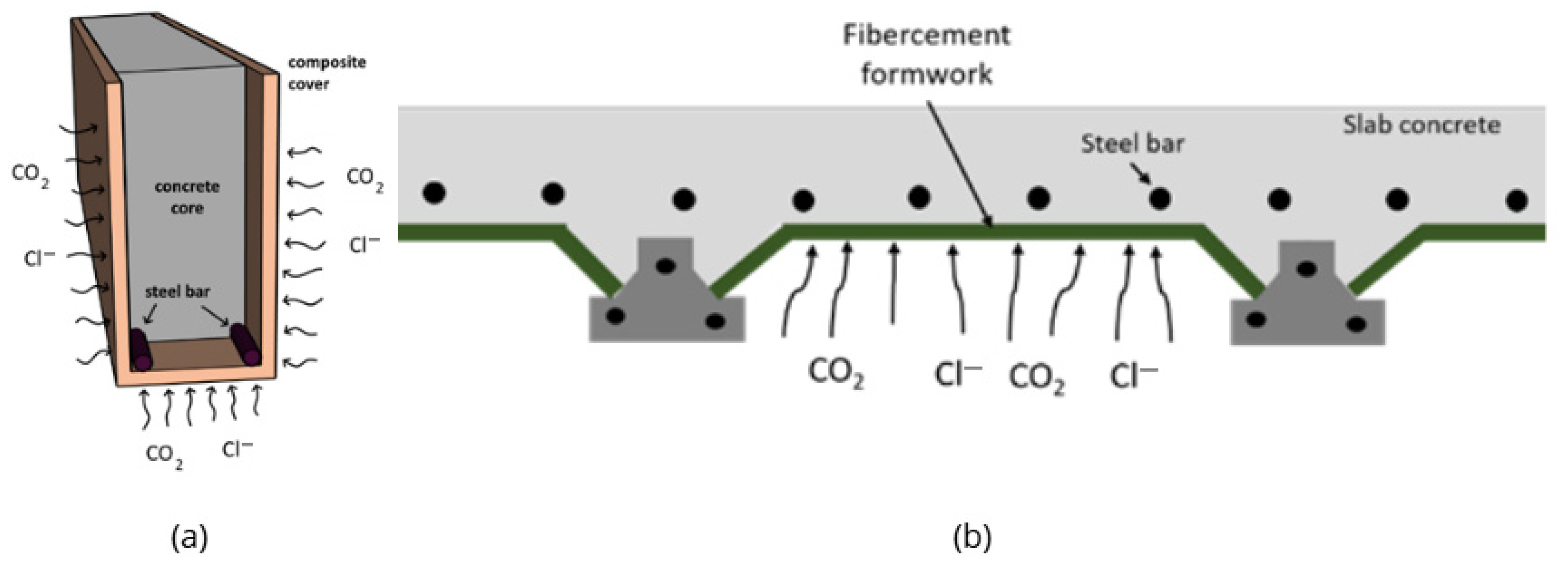
Figure 1. Permanent formwork for producing (a) beams and (b) reinforced concrete slabs (adapted by [2]).
Buildings 16 01628 g001
Figure 2. Casting of the samples in layers with external vibration: (a) first layer; (b) second layer; (c) third layer; (d) fourth layer.
Buildings 16 01628 g002
Figure 3. Setup of flexural test.
Buildings 16 01628 g003
Figure 4. Theoretical model of load versus crack opening behavior in the notched prism bending test [36].
Buildings 16 01628 g004
Figure 5. Specimens arranged in the (a) carbonation chamber and (b) estimate of the carbonated area, obtained with the aid of ImageJ 1.54r software.
Buildings 16 01628 g005
Figure 6. Effect of fiber content on relation to each physical property (water absorption, sorptivity, bulk density, capillary absorption and void ration) of composites F2, F4 and F6.
Buildings 16 01628 g006
Figure 7. Load versus crack opening diagram (CMOD) of the matrix (F0) and composites containing fibers (F2, F4, and F6), subjected to three-point bending tests.
Buildings 16 01628 g007
Figure 8. Cracking composites with (a) 2% and (b) 6% fibers, during the bending test (CMOD equal to 5 mm).
Buildings 16 01628 g008
Figure 9. Linear residual tensile model of the composite: (a) theoretical model and (b) models obtained experimentally for the composites.
Buildings 16 01628 g009
Figure 10. Influence of defects on ultrasonic pulse transmission, based on [51].
Buildings 16 01628 g010
Figure 11. Relationship between axial compressive strength and ultrasonic pulse velocity for fiber-reinforced composites containing sisal (present study), coconut [55], and bamboo fibers [56].
Buildings 16 01628 g011
Figure 12. Comparison between static and dynamic modulus of elasticity of composite (Ecomposite) and matrix (Ematrix) ratio as a function of fiber content.
Buildings 16 01628 g012
Figure 13. Depth of carbonation revealed after (a) 56 days, (b) 63 days and (c) 70 days of exposure to accelerated carbonation.
Buildings 16 01628 g013
Figure 14. Carbonation depths of matrix, composites and concrete after 56, 63 and 70 days of exposure to accelerated carbonation.
Buildings 16 01628 g014
Figure 15. Evolution of the carbonation depth of the F0, F2, F4, F6 and CC mixtures as a function of exposure time and determination of the accelerated carbonation coefficients.
Buildings 16 01628 g015
Table 1. Chemical composition, in oxides (% by mass), and loss on ignition (LOI) of the cement, silica fume and fly ash used.
OxideAmount (%, by Mass)
CementSilica FumeFly Ash
SiO216.1885.5156.61
Al2O33.761.4727.15
Fe2O33.775.136.27
CaO64.280.301.58
MgO4.901.401.70
K2O1.051.903.11
SO34.830.530.64
Na2O0.602.101.10
Other0.631.661.84
LOI (%)5.074.401.64
Table 2. Raw material consumption (kg/m3) of the reference matrix (F0, without fibers) and the cementitious composites containing 2% (F2), 4% (F4) and 6% (F6) of fibers, by mass.
Raw Material Consumption (kg/m3)Composites
F0F2F4F6
Cement382.28375.19368.37361.79
Fly ash339.80333.51327.44321.59
Silica fume127.43125.06122.79120.60
Sand849.51833.77818.60803.97
Water329.89329.34328.80316.09
Fiber-11.1221.8332.16
SP14.1613.9013.6430.82
VMA2.122.081.231.21
Water/cement ratio0.400.400.400.40
Table 3. Mixture (in mass) and raw material consumption (kg/m3) of concrete cover (CC).
Mixing
Characteristic
Raw Material
CementSandGravelWater/Cement Ratio
Mixture, by mass1.001.602.200.45
Consumption (kg/m3)459.58753.331011.08206.81
Table 4. Physical characterization of the concrete cover (CC) and of the reference cementitious composite (F0) and those containing varying levels of fibers (F2, F4, and F6).
Physical
Property
Composites *Concrete Cover
CC *
F0F2F4F6
Water absorption (%)9.39 ± 0.12 a7.54 ± 0.65 b9.23 ± 0.93 a,b11.25 ± 0.49 a,b5.43 ± 0.30 c
Void ratio (%)16.14 ± 0.15 a12.66 ± 1.09 b15.53 ± 1.59 c19.13 ± 0.79 a12.36 ± 0.59 b
Bulk density (%)1.72 ± 0.01 a1.68 ± 0.00 b1.68 ± 0.00 b1.70 ± 0.01 a2.28 ± 0.02 c
Capillarity (g/cm2)1.03 ± 0.32 a0.77 ± 0.30 a0.82 ± 0.29 a1.00 ± 0.44 a0.42 ± 0.17 b
Sorptivity (g/cm2.h0.5)0.25 ± 0.03 a0.18 ± 0.01 b0.19 ± 0.01 a,b0.20 ± 0.01 a,b0.15 ± 0.01 c
* For each property, equal letters represent statistically equal means.
Table 5. Mechanical characterization of reference cementitious composites (F0), fiber contents (F2, F4 and F6), and CC.
Mechanical
Property
Composites *Concrete Cover
CC *
F0F2F4F6
Compressive strength (fc, MPa)29.72 ± 3.07 a28.96 ± 2.12 a25.72 ± 2.13 a23.98 ± 2.81 a47.93 ± 3.60 d
Modulus of Elasticity (E, GPa)27.10 ± 1.70 a24.30 ± 1.55 b20.76 ± 0.71 c18.88 ± 0.59 c32.95 ± 1.56 d
Limit of proportionality (ffct,L, MPa)1.59 ± 0.28 a2.20 ± 0.07 a,b2.48 ± 0.09 b2.54 ± 0.13 b-
Residual stress 1 (fR,1, MPa)-1.64 ± 0.29 a2.91 ± 0.40 b3.57 ± 0.05 b-
Residual stress 2 (fR,2, MPa)-1.55 ± 0.25 a2.85 ± 0.45 b3.44 ± 0.09 b-
Residual stress 3 (fR,3, MPa)-1.30 ± 0.22 a2.21 ± 0.28 b2.68 ± 0.09 b
Residual stress 4 (fR,4, MPa)-1.09 ± 0.19 a1.84 ± 0.16 b2.15 ± 0.06 b
* For each property, equal letters represent statistically equal means.
Table 6. Ultrasonic wave propagation velocity (V) and dynamic modulus of elasticity (Ed) of cementitious composites reinforced with sisal fibers.
Composites *V (km/s)Ed (GPa)
F03.81 ± 0.03 a22.49 ± 0.02 a
F23.78 ± 0.02 a21.58 ± 0.18 b
F43.74 ± 0.02 a,b21.22 ± 0.21 b,c
F63.68 ± 0.04 b20.76 ± 0.48 c
* For each property, equal letters represent statistically equal means.
Table 7. Average carbonated area of samples F0, F2, F4, F6 and CC after 56, 63 and 70 days of exposure to accelerated carbonation.
MixtureAverage Carbonated Area (mm2)
56 Days63 Days70 Days
F0432.19 ± 73.30445.84 ± 28.01552.49 ± 30.37
F2406.60 ± 62.06417.67 ± 35.40426.53 ± 97.30
F4450.37 ± 24.48511.05 ± 21.39600.80 ± 36.68
F6834.19 ± 47.051336.77 ± 81.321483.32 ± 86.83
CC316.13 ± 16.65401.42 ± 39.19411.96 ± 22.91
Table 8. Correlation indices (x′) between carbonation coefficients obtained through accelerated tests and under natural exposure conditions proposed by [57].
EnvironmentCorrelation Index (x′) Between Kacel. and Knat.
Rural or Urban Light (%CO2 < 0.04)8.0
Medium Urban (0.04 ≤ %CO2 < 0.06)7.5
Urban Heavy * or Light Industrial (0.06 ≤ %CO2 < 0.10)7.0
Heavy Industrial ** (0.10 ≤ %CO2 < 0.30)3.0
* High population density with heavy vehicle traffic. ** Specific urban sites, such as tunnels and garages (or parking lots), can have CO2 concentrations equivalent to those in industrial areas.
Table 9. Carbonation coefficients obtained through accelerated tests in addition to the useful life (UL), considering a cover thickness of 30 mm.
EnvironmentMixtureKacel. (mm/Year−0.5)Knat. (mm/Year−0.5)UL (Years)
Rural or Urban Light
(%CO2 < 0.04)
F011.461.43438.56
F210.061.26569.39
F412.511.56368.28
F629.113.6467.95
CC9.051.13703.80
Medium Urban
(0.04 ≤ %CO2 < 0.06)
F011.461.53385.45
F210.061.34500.44
F412.511.67323.69
F629.113.8859.72
CC9.051.21618.57
Urban Heavy or Light Industrial
(0.06 ≤ %CO2 < 0.10)
F011.461.64335.77
F210.061.44435.94
F412.511.79281.97
F629.114.1652.02
CC9.051.29538.84
Heavy Industrial
(0.10 ≤ %CO2 < 0.30)
F011.463.8261.67
F210.063.3580.07
F412.514.1751.79
F629.119.709.56
CC9.053.0298.97
Disclaimer/Publisher’s Note: The statements, opinions and data contained in all publications are solely those of the individual author(s) and contributor(s) and not of MDPI and/or the editor(s). MDPI and/or the editor(s) disclaim responsibility for any injury to people or property resulting from any ideas, methods, instructions or products referred to in the content.