Article

Layered Spatial Articulation and Base Spatial Graph: Formalizing Structural Preconditions of Architectural Spatial Analysis

by
Daegeon Lee
and
Jaewoo Yoo
*
Department of Architecture, Pusan National University, Busan 46241, Republic of Korea
*
Author to whom correspondence should be addressed.
Buildings 2026, 16(8), 1536; https://doi.org/10.3390/buildings16081536
Submission received: 25 February 2026 / Revised: 5 April 2026 / Accepted: 9 April 2026 / Published: 14 April 2026
(This article belongs to the Section Architectural Design, Urban Science, and Real Estate)

Abstract

Graph-based spatial analysis formalizes relations among spatial units, but the formation of these units and their boundary correspondences remains under-specified. This study defines the structural stage preceding relational abstraction and establishes the conditions under which spatial units and boundary correspondences become analytically determinate. It then develops a layered spatial articulation procedure that derives spatial objects from plan-encoded architectural information by differentiating topographic substrate, building frame, spatial enclosure, and relational boundary conditions. These are organized into a base spatial graph. The topology of this graph is fixed by articulation, and its edges encode admissible relational mode combinations. Using traditional Korean housing (hanok) as an illustrative reference for the proposed methodology, the study shows that heterogeneous spatial conditions can be consistently articulated into a unified structural domain prior to relational abstraction. The resulting base spatial graph defines a finite but combinatorially extensive space of admissible relational configurations. Within this domain, graph-domain operations act without expanding the articulated structure, while certain operations may reduce it through structural transformation. The study shows that spatial units cannot be treated as pre-given entities but must be structurally constituted. By formalizing this prior stage, the study establishes explicit structural preconditions for graph-based spatial analysis and provides a consistent analytical domain for subsequent spatial interpretation.

1. Introduction

1.1. Research Background

Graph-based approaches to architectural space have been widely employed across spatial analysis, design, and operational applications. In such approaches, spatial objects are represented as nodes and boundaries between them as edges, allowing architectural space to be organized into a graph structure [1,2]. Graph-based analyses have been widely applied to residential and apartment layouts, including studies of housing and urban dwelling types [3,4,5]. This approach has also been adopted across multiple spatial modeling contexts, ranging from urban-scale networks to indoor environments, where standards such as IndoorGML employ graph structures to encode connectivity relations [6,7,8,9].
In such approaches, graph representations operate under the assumption that spatial objects are already defined. A graph does not establish spatial objects by itself; rather, it operates on predefined spatial objects and the relations organized among them [10]. Consequently, the process by which spatial graphs are formed is typically excluded from the analytical procedure. Spatial objects are generally defined based on whether partitioning elements—such as walls—form closed boundaries, with additional subdivisions introduced as needed [11].
Recent advances in plan recognition, semantic segmentation, and model reconstruction have introduced data-driven methods for automatically extracting spatial structures from architectural drawings or constructing graph-based representations of space [12,13,14]. However, these approaches primarily focus on automating the derivation of spatial objects and relations from given representations, rather than formally specifying the conditions under which spatial objects are constituted.
The way spatial objects are formed directly determines both the structure of the graph and the scope of analysis. When spaces with different physical conditions are represented as equivalent nodes, their distinctions are not preserved in the graph. Spatial relations are reduced to connections between nodes, and analysis is conducted on the basis of this simplified structure. Even when additional analytical concepts are introduced, they remain external to the graph structure and are incorporated interpretively rather than structurally [15]. This tendency, in which spatial relations are reduced to limited dimensions such as movement or connectivity, has also been critically discussed in prior studies [16].
Architectural space, however, has long been recognized as being formed under diverse conditions that cannot be reduced to a single defining criterion [17,18]. This heterogeneity becomes particularly evident in architectural contexts where multiple spatial conditions coexist within a single structural system. While spatial objects may be read through a structural system, other architectural conditions—such as enclosure, structure, and floor systems—may simultaneously give rise to spatial configurations that partially diverge from that structural reading [19]. Under such conditions, approaches that treat spatial objects as if they were determined by a single criterion fail to account for the multiplicity of spatial configurations and the conditions under which spatial objects are constituted.
The structure of this problem can be represented as shown in Figure 1.
Figure 1 illustrates how spatial objects are implicitly formed from spatial conditions, where spatial units and boundary-related relational objects are jointly generated, and their relations are subsequently reduced to connectivity-based representations in the graph structure. Such a procedure constrains the representation of spatial relations and, consequently, limits the scope of analytical interpretation. This limitation becomes particularly evident in architectural contexts where heterogeneous spatial conditions coexist within a single structural system.
This limitation does not arise from the graph itself, but from the procedure by which space is formed into a graph. A graph is a tool for representing a given structure, and the scope of analysis is determined by how that structure is constituted. Therefore, the formation of a spatial graph must be treated as an explicit part of the analytical procedure, requiring the specification of the conditions under which spatial objects are constituted and relations are abstracted.

1.2. Research Objective and Methodological Position

This study addresses the problem that the process by which spatial objects—including spatial units and relational objects—are formed is not explicitly defined in graph-based spatial analysis. When this process is incorporated into the analytical procedure, spatial objects and their relations can be constituted as an analytically consistent structure.
To this end, the study proposes a methodological framework that explicitly constructs the procedure by which architectural space is formed and spatial relations are established as part of the analytical process. This procedure distinguishes spatial conditions structurally and derives spatial objects and boundary correspondences from them. Through this, the resulting spatial graph provides a structural basis capable of accommodating diverse analytical concepts.
This study is methodological in nature and aims to explicitly construct the structural preconditions under which graph-based spatial analysis operates.

1.3. Structure of the Research

This paper develops an analytical procedure that proceeds from the observation of spatial conditions to the structural determination of spatial objects, and subsequently to graph-domain operations.
  • Section 2 examines historically recognized architectural spaces through selected precedents, demonstrating that architectural space cannot be reduced to a single defining criterion. It then introduces East Asian timber-framed housing as a reference case, through which the coexistence of heterogeneous spatial conditions within a single structural system can be observed. This analysis shows that spatial objects cannot be assumed as given, but must be structurally constituted.
  • Section 3 presents the methodological framework of the study by formulating a procedure for the layered articulation of spatial conditions and constructs analytically determinable spatial objects based on plan-encoded information. It then organizes these articulated entities into a base spatial graph, establishing the structural domain upon which subsequent analysis operates.
  • Section 4 formalizes graph-domain operations on this determined structure. It distinguishes structural transformation, semantic annotation, and graph representation, and specifies the conditions under which topology is preserved or altered.
  • Section 5 discusses the analytical implications, scope, and limitations of the proposed framework and evaluates its relationship to existing graph-based spatial analysis methods.

2. Implicit Conditions of Historically Recognized Architectural Space

This section examines, in a stepwise manner, the conditions under which architectural space cannot be defined by a single criterion, through case-based and structural analysis. To this end, it first identifies the heterogeneity of spatial recognition through historically recognized configurations of architectural space. It then analyzes how differences in structural systems are reflected in how spatial conditions are articulated. Subsequently, a case is introduced in which these conditions appear simultaneously, allowing the spatial configuration of an actual architectural context to be observed. Finally, the observed spaces are organized into analytically comparable dimensions, demonstrating that spatial units cannot be assumed as pre-given.

2.1. Diversity of Historically Recognized Architectural Spaces

Across architectural history, a wide range of spatial configurations have been consistently recognized as architectural space [20]. These spaces do not share a single formal definition. Spaces differ in enclosure condition, structural basis, vertical organization, and modes of access, and such variation makes it difficult to define spatial units according to a single criterion.
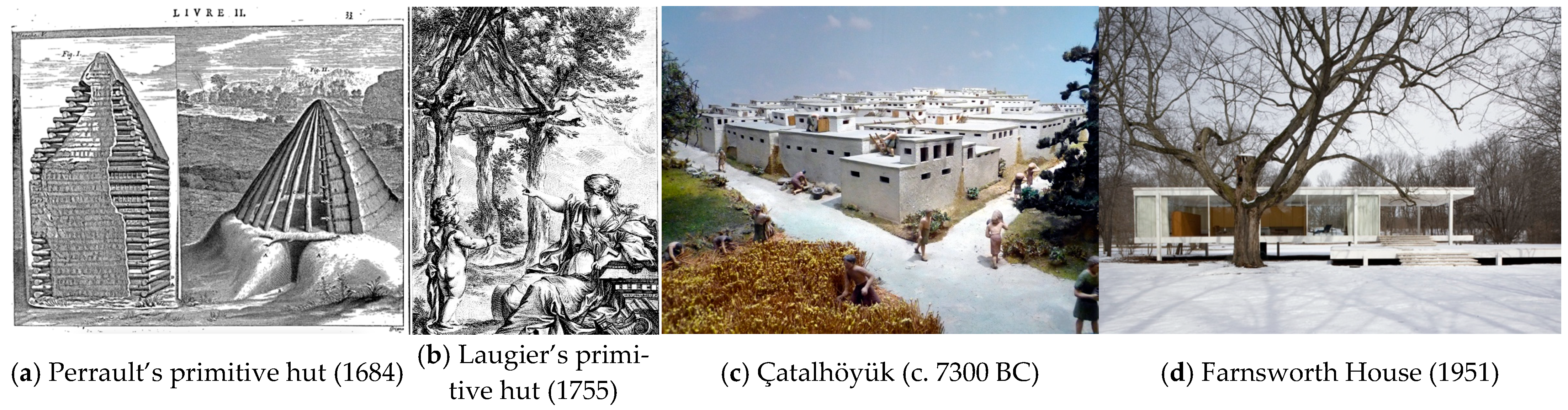
Figure 2 presents representative cases illustrating this diversity. Architectural space has been articulated through different combinations of roof, boundary, ground condition, and access logic, resulting in structurally distinct spatial configurations. This divergence is already evident in early theoretical representations. Classical depictions of the primitive hut present architectural space as the domain beneath a roof, yet they diverge fundamentally in how this domain is structured.
In Perrault’s depiction, architectural space is understood as an enclosed interior formed through topographic modification beneath a roof [21]. In contrast, Laugier recognizes the space articulated by an exposed structural frame under a roof as architectural space, even in the absence of enclosing walls [22]. While both models privilege the roof, they differ decisively on whether enclosure is a necessary condition of spatial recognition.
Taken together, these cases demonstrate that architectural space has historically been articulated through different structural and topographic bases. It cannot be reduced to enclosure alone, nor to a single spatial criterion.
Archaeological evidence reinforces this point. The Neolithic settlement of Çatalhöyük presents a complex organization of enclosed interior cells, shared courtyards, and roof-level domains. Spatial recognition is vertically distributed: access occurs predominantly from above, and collective life unfolds across roofs and courtyards as much as within enclosed interiors. Spatial determination is therefore not confined to enclosed volumes but extends across multiple levels and structural conditions.
Modern architecture continues to operate within this expanded repertoire. The Farnsworth House articulates architectural space through elevated horizontal planes organized by a vertical building frame. A glazed interior, surrounding terraces, and an elevated platform together form a spatial system in which visual permeability and enclosure coexist. Spatial articulation here emerges from the interplay of structural frame, floor condition, and boundary treatment rather than enclosure alone.
Table 1 summarizes these reference cases by identifying their spatial basis, recognized spaces, enclosure type, and access mode. Considered together, the figure and table demonstrate that architectural space has historically encompassed enclosed interiors, structurally open roofed domains, elevated platforms, courtyards, and roof-level spaces. These are not marginal exceptions, but recurrent architectural constructs grounded in distinct structural logics.
This observation has direct methodological implications. If architectural space has been historically recognized in heterogeneous structural forms, spatial analysis cannot begin from a single pre-given spatial unit. Instead, it must specify how spatial objects are constituted as analytically determinable entities under specific structural conditions, prior to graph representation and relational abstraction.

2.2. Structural Articulation of Spatial Conditions and Case Selection

As established in the preceding discussion, architectural space has been recognized under diverse conditions that cannot be reduced to a single criterion. Under such circumstances, taking spatial units as the starting point of analysis requires a case in which their non-self-evident nature can be clearly revealed. In other words, cases where heterogeneous spatial conditions coexist within a single building—such that these units cannot be stably defined by a single partitioning criterion—are particularly appropriate for analysis.
By contrast, when analysis focuses on residential types with relatively homogeneous conditions, such units tend to be defined in a largely self-evident manner based on enclosure or geometric partitioning. Analysis is still possible in these contexts. However, the problem of unit formation remains largely concealed, and the need for a more explicit analytical procedure becomes less apparent.
For this reason, an architectural type that exhibits structurally differentiated spatial conditions is required. Frame-based architectural systems provide such a context. Because structural frames are organized independently of enclosure, spatial configurations do not remain fixed in advance but instead emerge through the interaction of structure, enclosure, and floor systems [19]. Under these conditions, units are not determined by a single criterion; rather, they are constituted through the combination of multiple structural factors.
East Asian traditional housing offers an appropriate scope for observing such differentiation, as it shares timber-framed construction systems. Yet the ways in which these conditions are articulated differ. Chinese traditional dwellings, for instance, tend to mediate spatial differentiation primarily through enclosure systems, even where timber structures are present [23]. In these contexts, variation exists, but the formation of units remains relatively constrained. By contrast, Japanese traditional housing regulates openness through movable partitions while maintaining comparatively homogeneous floor systems, again limiting the range within which units are formed.
Traditional Korean housing (hanok), by contrast, systematically combines heterogeneous floor systems—most notably heated ondol floors and unheated wooden floors—within a single post-and-beam structural system. This produces spatial conditions articulated through multiple criteria. Enclosed rooms, permanently open wooden floors, semi-exterior transitional spaces, and courtyards coexist within a single building, each formed through different combinations of structural frame, enclosure, and floor conditions [24,25].
Such a configuration makes the problem explicit. Units cannot be determined by a single criterion; they must be constituted through the interaction of varied structural conditions. For this reason, this study adopts hanok as an architectural type in which heterogeneous spatial conditions coexist most clearly.
This architectural context makes it possible to examine how spatial units cannot be assumed as pre-given, but instead must be constituted under specific structural conditions. Based on this premise, the following section develops a layered spatial articulation procedure through which such conditions are rendered analytically determinable as spatial objects prior to graph-domain operations.

2.3. A Reference Case for Observing Spatial Conditions: Gwangajeong

As established in Section 2.2, spatial units cannot be assumed as pre-given under a single criterion, but must instead be constituted under specific structural conditions. To examine this in built architecture, a case is required in which heterogeneous spatial conditions appear simultaneously within a single structural system. The reference case is therefore selected for its structural clarity in exposing non-coincident spatial determinants, which are essential for demonstrating the problem addressed in this study.
To this end, this study adopts Gwangajeong (觀稼亭), an early-Joseon traditional residence located in Yangdong Village, Gyeongju, as a reference case. Gwangajeong is based on a post-and-beam structural system and comprises multiple spatial types within a single architectural body, including enclosed ondol rooms, wooden-floored halls such as the daecheong, auxiliary wooden platforms (numaru), a kitchen, entrance spaces, and interior and exterior courtyards [26]. It is situated on a gently sloping site, clearly revealing differences in floor levels and vertical spatial relationships. In this configuration, structural frame, enclosure, and floor conditions participate in the articulation of spatial conditions in different ways.
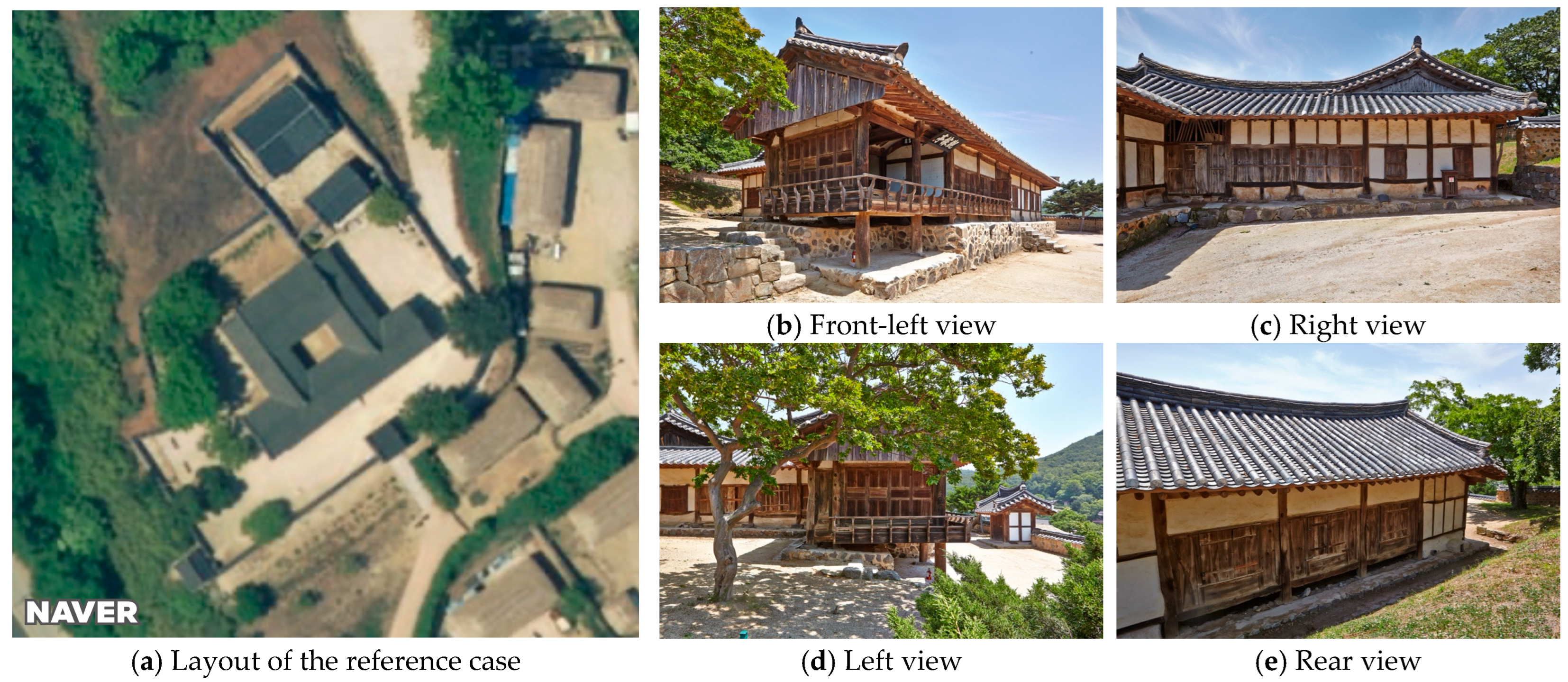
Figure 3 presents the overall configuration of the reference case, including the site layout and exterior views that reveal the relationship between structural framing, enclosure, floor elevation, and access.
Within this reference case, the principal areas consistently recognized as architectural space include:
  • Enclosed ondol rooms (spaces with heated floor systems);
  • The daecheong (main wooden-floored hall);
  • Subsidiary wooden-floored spaces, including the numaru (raised wooden platform) and small daecheong;
  • The kitchen;
  • The entrance gate space;
  • Inner and outer courtyards.
Although all these areas are traditionally recognized as architectural space, they differ markedly in how spatial boundaries are articulated and perceived. Differences appear in the presence and character of upper surfaces, in floor level and construction, in the clarity and permanence of lateral boundaries, in degrees of openness, and in modes of access. Some spaces function as fully enclosed interiors, while others are recognized primarily through an upper surface, or even without clearly defined side boundaries. Even within the same structural frame, spatial character varies substantially according to floor condition and openness.
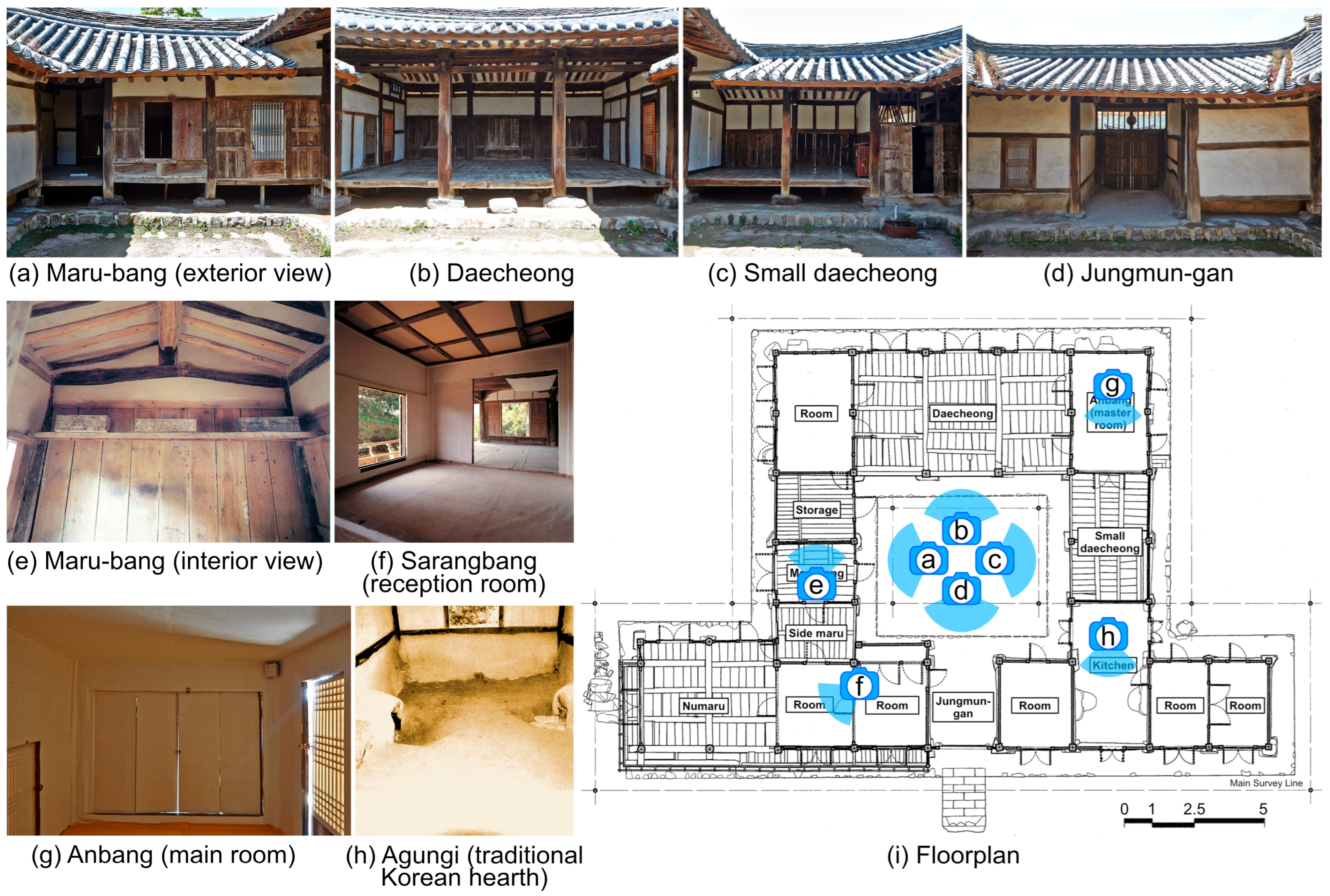
Figure 4 provides reference images corresponding to the major spatial areas identified on the plan of Gwangajeong, allowing differences in spatial constitution to be observed directly. At this stage, the observations remain descriptive. Spatial units are not yet formalized as analytical objects, nor are explicit criteria imposed upon their boundaries.
These observations indicate that spatial recognition in hanok does not rely on a single defining criterion, but emerges through different combinations of roof, floor, boundary, and access conditions. The following section examines these spaces more systematically—not by assuming them as pre-given analytical units, but by formulating a layered spatial articulation through which these differentiated conditions become analytically determinable prior to relational abstraction and graph-domain analysis.

2.4. Observed Spatial Conditions in the Reference Case

In the preceding section, a range of spaces conventionally recognized as architectural space in hanok was examined. Although these spaces are treated as architectural space in practice, the physical conditions under which they are recognized as spatial domains are not uniform and cannot be reduced to a single defining criterion. Spatial recognition emerges through varying combinations of upper surfaces, floor conditions, lateral enclosure, and patterns of use. These dimensions correspond to long-recognized components of architectural space in architectural design theory [18], yet their analytical integration remains implicit in plan-based spatial analysis.
This section makes these differences comparable by distinguishing the structural conditions under which architectural space is observed to emerge. It identifies recurring observational dimensions and examines how they combine across spatial types.

2.4.1. Observational Dimensions for Comparing Spatial Conditions

Table 2 compares the principal spatial types observed in Gwangajeong using five dimensions: upper surface, floor condition, lateral enclosure, spatial domain character, and associated activities. These dimensions do not function as criteria of definition, nor do they establish hierarchy. They serve as descriptive variables through which heterogeneous spatial recognition can be compared.
Upper surface denotes the presence of an operative overhead condition, realized as a ceiling, roof, or extended eaves. Floor condition refers to the supporting base enabling occupation, including ondol flooring, wooden flooring, stylobate surfaces, or earth. Lateral enclosure describes the presence or absence of vertical bounding elements such as walls, gates, or partial partitions.
Spatial domain character indicates how spatial extent is stabilized in perception, ranging from clearly defined interiors to mixed interior–exterior domains and exterior domains bounded by surrounding structures. Associated activities are included not as determinants of articulation, but as historically reinforced correlates of spatial recognition.
Importantly, these conditions are legible at the level of the architectural plan in hanok. Elements such as columns, walls, floor types, hearths, gates, and raised platforms are conventionally encoded, allowing upper surfaces, floor conditions, and enclosure to be identified or inferred. The operative presence of these elements is analytically more decisive than their precise geometric form, as it conditions how spatial domains are recognized and differentiated.

2.4.2. Differentiation Across Major Spaces in Gwangajeong

When the principal spaces of Gwangajeong are examined, it becomes evident that architectural space is articulated through heterogeneous combinations rather than a single spatial logic, making it difficult to define spatial units on the basis of a single criterion. Ondol rooms exhibit clearly defined domains through the combined presence of ceiling, heated floor, and enclosing walls. By contrast, the daecheong shares the same roof structure but is recognized as a mixed interior–exterior domain due to its wooden floor and variable lateral openness.
Side maru and under-eaves spaces lack fixed lateral enclosure, yet form stable spatial domains through upper surface continuity and attachment to the building frame. Jungmungan operates as a semi-exterior buffering domain defined by roof and stylobate conditions. Courtyards, despite lacking upper enclosure at the building scale, are recognized as spatial domains through enclosure by surrounding structures and consistent patterns of use.
These comparisons demonstrate that enclosure by walls is neither necessary nor sufficient for architectural space. Distinct spatial domains arise from different structural combinations. No single condition independently determines spatial recognition.

2.4.3. Methodological Implications

The spaces observed in Gwangajeong satisfy only subsets of the dimensions identified above; full coincidence of all conditions is uncommon. Architectural space in hanok therefore does not consist of uniform spatial units, but of heterogeneous spatial domains articulated within a stable structural order.
This observation carries direct methodological implications. If architectural space emerges from variable combinations of upper surfaces, floor conditions, and lateral enclosure, then spatial units cannot be presupposed as uniform entities in spatial analysis. Analytical models that assume a single enclosure-based unit inevitably suppress structural heterogeneity.
Studies applying configurational analysis to hanok have described spatial characteristics within predefined units [4,27]. By contrast, the present study addresses a prior question: under what structural conditions do such units become analytically determinable?
Relational abstraction therefore requires that spatial units first be constituted as analytically determinable entities. This requires a procedural articulation that specifies how spatial domains are determined under given structural conditions prior to graph-domain operations.

3. Methodological Framework: Layered Spatial Articulation and Base Graph Construction

This section presents the methodological framework of the study and establishes the structural conditions under which spatial units and boundary correspondences can be consistently constructed in graph-based spatial analysis. As discussed in Section 2, architectural space extends beyond regions fully enclosed by vertical partitioning elements such as walls; partially open or structurally differentiated areas are also recognized as spatial domains [11]. Under such conditions, spatial boundaries are established through criteria beyond enclosure, and spatial units are treated as analytical constructs rather than pre-given entities constituted under architectural conditions [19]. The formation of spatial units and boundary correspondences is therefore addressed simultaneously, while relational interpretation is deferred to subsequent stages.
To address this problem, the study introduces an explicit intermediate stage between plan-encoded information and graph-domain operations as a formalized analytical procedure. Architectural representation is treated as a problem of structured formalization rather than a simple diagrammatic depiction [28]. The articulation, determination, and structuring processes presented here make explicit the procedure of spatial object formation and graph abstraction implicit in Figure 1. Architectural space is articulated across analytically defined layers from which spatial objects are constituted, and their topology is structured as a base spatial graph. This staged configuration ensures that graph-based abstraction remains grounded in articulated spatial objects while preserving a traceable linkage to plan-encoded information.

3.1. Analytical Structure of the Methodological Framework

This subsection defines the analytical structure of the methodological framework proposed in this study. When graphs are derived solely from enclosed units, partially enclosed domains—such as open halls, raised platforms, and under-eaves areas—lack determinate closure rules and must be resolved interpretively. In frame-based architecture, where building frame and spatial enclosure may diverge, such interpretive closure introduces arbitrariness. Adjacency between spatial units does not necessarily imply relational operability, and spatial relations frequently exceed simple connectivity.
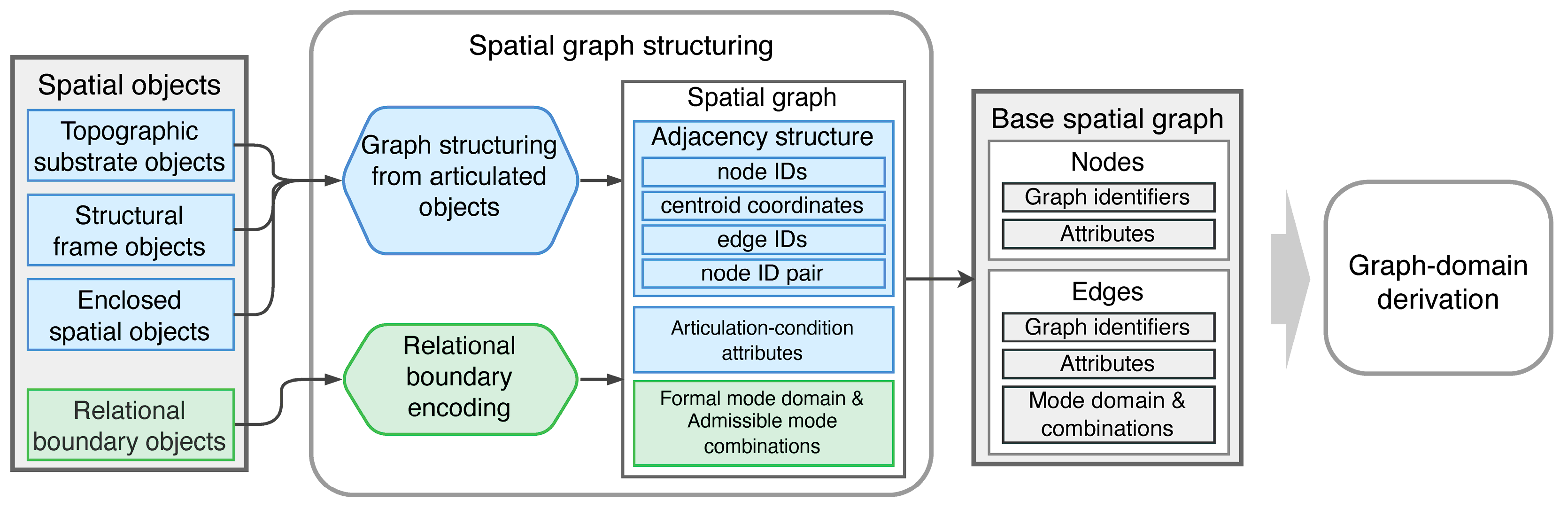
The proposed procedure therefore distinguishes two sequential processes, as illustrated in Figure 5.
First, layered spatial articulation determines spatial objects across the topographic substrate, building frame, spatial enclosure, and relational boundary layers. Within each layer, plan-encoded geometry is identified, spatial elements are derived under rule-based criteria, and these elements are composed into layer-specific spatial objects. This articulation renders heterogeneous structural conditions explicit without collapsing them into a single enclosure-based logic.
Second, spatial graph structuring organizes these articulated entities into a base spatial graph. Nodes correspond to articulated spatial objects, and edges correspond to boundary correspondences established during articulation. The resulting base spatial graph constitutes the articulated structural domain of the plan: it preserves the complete topological structure together with articulation condition attributes and edge-level admissible mode combination sets.
At this stage, no semantic annotation, structural transformation, or representational operation is applied. The base spatial graph serves as the structurally complete reference domain for subsequent graph-domain operations. Analytical variation does not generate new spatial objects; it proceeds by operating on an already determined graph.
By separating layered spatial articulation and spatial graph structuring from graph-domain operations, the procedure clarifies the logical distinction between structural determination and subsequent analytic derivation. The following sections describe each stage of this methodological procedure in detail, within which the decision criteria guiding the identification and construction of spatial objects and boundary correspondences are made explicit in relation to the analytical perspective.

3.2. Layered Spatial Articulation

3.2.1. Conceptual Structure of Layered Spatial Articulation

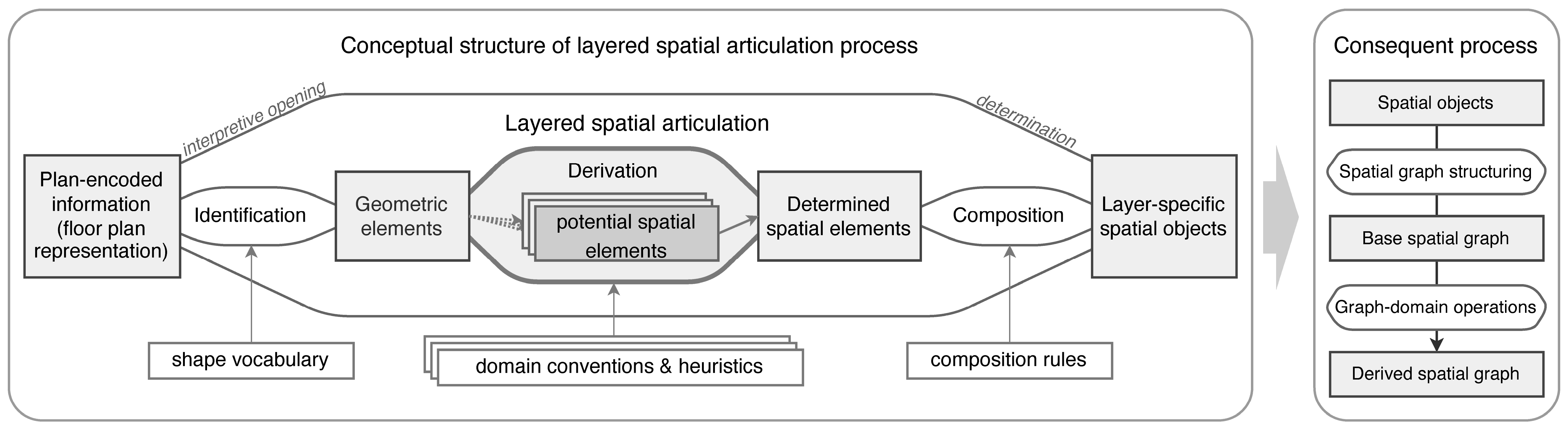
Layered spatial articulation establishes the structural basis upon which architectural space becomes analytically determinate prior to spatial graph structuring. Rather than presupposing spatial units as given entities, articulation differentiates the structural conditions embedded in plan-encoded information and renders them explicit.
As illustrated in Figure 6, articulation follows a recurring object–process–object structure. Plan-encoded information functions as the initial object. Through staged operations of identification, spatial derivation, and composition, spatial objects are articulated within analytically distinct layers.
Space does not exist independently of material conditions. It emerges relationally through reference to topographic support, building frames, enclosure systems, and boundary devices. Spatial abstraction therefore depends on structurally encoded conditions; without such reference, it becomes indeterminate. The analytical separation of spatial determinants aligns with earlier discussions on geometric and environmental organization [10].
If space is relational, the elements through which it emerges are likewise relational. The components articulated across layers—topographic substrate, building frame, spatial enclosure, and relational boundary devices—do not impose hierarchy in advance. Through procedural articulation, however, they reveal structural dependency and relative analytical priority.
Architectural floor plans encode heterogeneous structural determinants: ground conditions, frame systems, enclosure surfaces, and boundary devices. These determinants do not coincide and cannot be reduced to a single spatial logic. In frame-based architecture, building frame modularity, enclosure geometry, and topographic differentiation frequently diverge. A unit defined by enclosure may not coincide with a structural bay; a structural module may not define inhabitable space; a platform may extend beyond both frame and enclosure limits.
Layered spatial articulation separates these irreducible determinants into analytically distinct layers:
  • The topographic substrate layer, articulating ground continuity and elevation;
  • The building frame layer, articulating modular spatial capacity;
  • The spatial enclosure layer, articulating bounded or partially bounded extents;
  • The relational boundary layer, articulating boundary devices that condition admissible relational modes.
Each layer articulates spatial objects according to its own structural logic. The resulting spatial objects remain analytically differentiated and traceable in subsequent spatial graph structuring and graph-domain operations.
Layered spatial articulation thus precedes spatial graph structuring. It makes explicit the structural conditions under which spatial entities emerge, without yet organizing them into a relational graph.

3.2.2. Articulation Procedure Across Layers

Layered spatial articulation operates through a staged procedure consistently applied across analytical layers. Although each layer articulates spatial objects under distinct structural criteria, the procedural logic of articulation remains invariant.
Within each layer, articulation proceeds through three operations. Identification recognizes plan-encoded geometries and encodes them as geometric elements defined by layer-specific structural conditions. At this stage, articulation remains internal to the layer.
Spatial derivation interprets identified geometric elements using explicit analytical criteria derived from structural and geometric conditions. Derivation resolves geometric indeterminacy while preserving traceability to plan-encoded information. Where geometric configurations admit multiple plausible readings, derivation permits controlled inter-layer reference in order to maintain procedural consistency.
Composition combines derived spatial elements under explicit layer-specific conditions to instantiate layer-specific spatial objects. Composition establishes determinate spatial extents and boundary conditions without collapsing distinctions among layers.
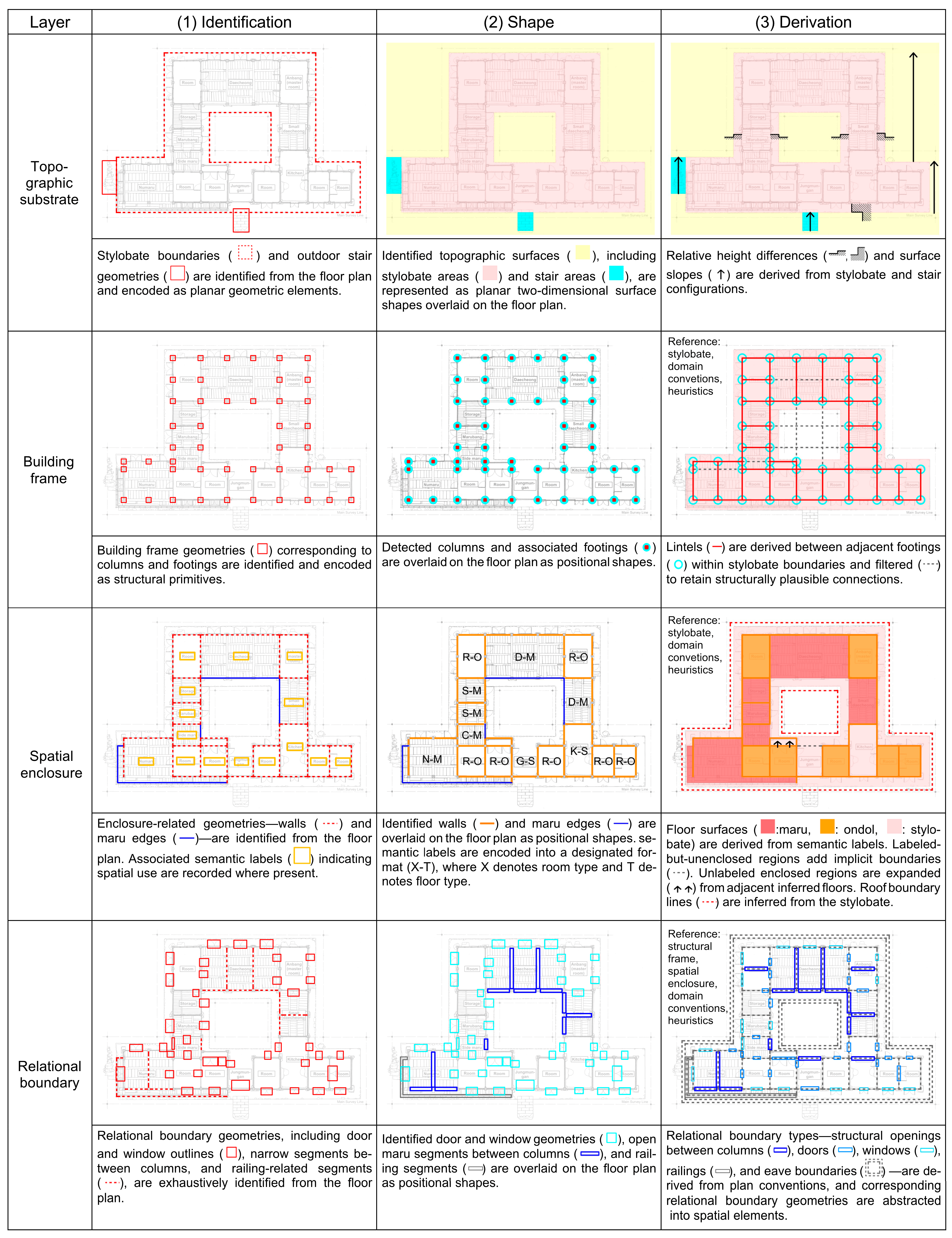
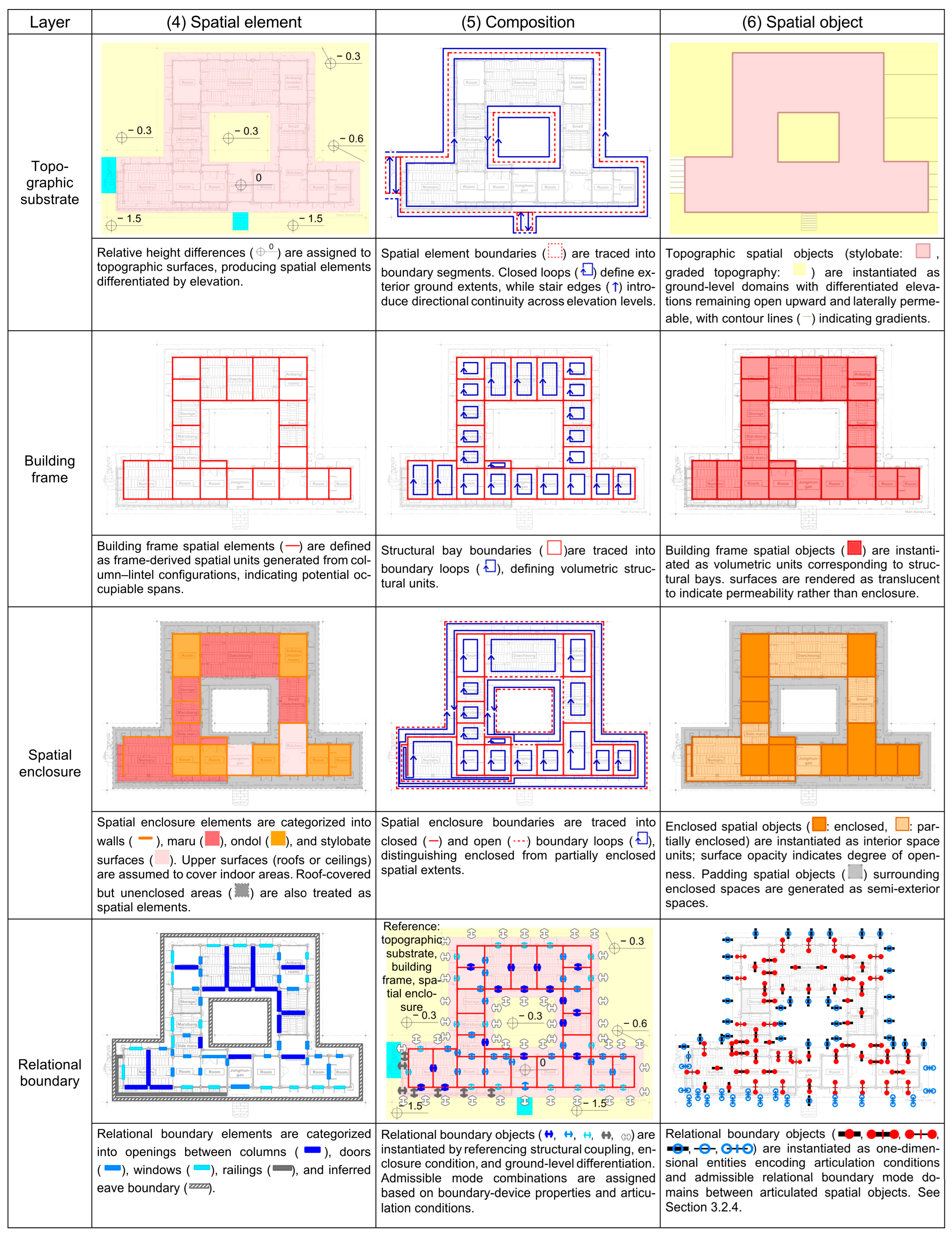
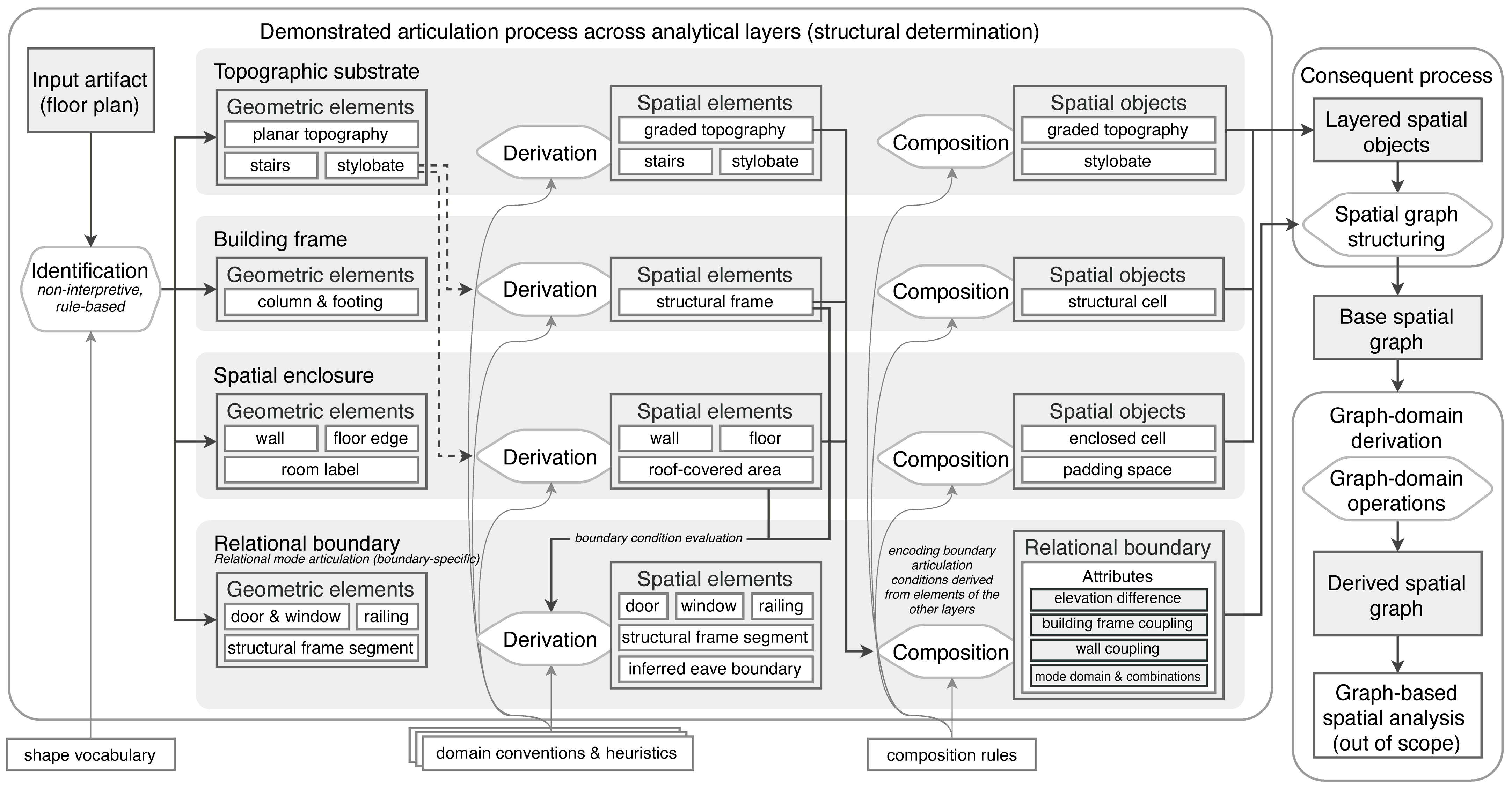
Figure 7 demonstrates this staged articulation process across the topographic substrate, building frame, spatial enclosure, and relational boundary layers. Identification and composition operate strictly within layer-specific constraints, whereas derivation may invoke limited cross-layer reference. Such reference does not introduce conceptual hierarchy; it defines procedural admissibility within articulation.
Through this regulated procedure, layered spatial articulation produces analytically determinate spatial objects while preserving differentiated structural conditions. This procedure is guided by explicit decision criteria:
  • Boundary elements are identified as geometric primitives corresponding to structurally or materially defined edges in the plan.
  • Closed loops are established when boundary elements form continuous enclosure under layer-specific structural conditions.
  • Spatial objects are instantiated from closed loops or from structurally supported open domains that satisfy layer-specific conditions.
  • Relational boundary objects are determined by admissible mode combinations rather than geometric configuration alone.
  • Inter-layer reference is permitted only when necessary to resolve geometric indeterminacy, without collapsing distinctions between layers.
These criteria formalize the articulation process by explicitly defining the conditions under which spatial objects and boundary correspondences become analytically determinate.

3.2.3. Structured Articulation and Controlled Inter-Layer Reference

Layered spatial articulation differentiates structural conditions that are physically embedded in architectural construction. The analytical layers—topographic substrate, building frame, spatial enclosure, and relational boundary—correspond to material dependencies observable in plan-encoded information.
What appears in plan drawings as distinct geometric elements reflects an underlying structural order: ground support precedes framing; framing conditions enclosure; enclosure conditions boundary articulation. Analytical layering does not impose hierarchy; it makes these dependencies explicit without reducing them to a single spatial logic.
Figure 7 visualizes this structured articulation. It shows staged derivation of spatial objects with controlled inter-layer reference. Analytical independence among layers is preserved, even where procedural coordination is required for determinacy. Layered spatial articulation therefore renders spatial objects structurally determinate prior to spatial graph structuring.
Figure 8 makes explicit the structured articulation procedure and the admissible conditions of inter-layer reference. Although layers are analytically differentiated, articulation reveals that spatial objects cannot become analytically determinate without limited cross-layer coordination. Building frame articulation presupposes topographic support; spatial enclosure presupposes building frame; relational boundary articulation presupposes enclosure and frame conditions.
This dependency does not establish conceptual hierarchy. Rather, it reflects physical interdependence translated into procedural admissibility during spatial derivation. Identification operates independently within each layer, yet derivation may require reference to spatial objects in adjacent layers in order to resolve geometric indeterminacy. Once admissible reference has occurred, composition proceeds under layer-internal rules.
Layered spatial articulation therefore reveals a structured dependency network rather than a hierarchical order. If space is relational, the elements through which space emerges are likewise relational. The structured procedure exposes dependency without reduction. Analytical differentiation among layers is preserved, even as articulation acknowledges controlled inter-layer reference as necessary for determinate spatial articulation.
Through this structured articulation procedure, spatial objects become analytically determinate while retaining traceability to the material and structural conditions encoded in the plan. This prepares the transition to spatial graph structuring, where articulated objects are reorganized into a formally defined topological structure.

3.2.4. Relational Boundary Layer and Admissible Mode Determination

In addition to the topographic substrate, building frame, and spatial enclosure layers, layered spatial articulation includes a relational boundary layer. Unlike the preceding layers, this layer does not articulate spatial extents. Instead, it determines admissible boundary modes between already articulated spatial objects.
Relational boundary articulation follows the same staged procedure of identification, spatial derivation, and composition.
  • During identification, boundary-related geometries—such as openings, gates, railings, thresholds, and topographic discontinuities—are extracted from plan-encoded information.
  • During spatial derivation, these geometries are interpreted under explicit analytical criteria and associated with boundary correspondences between articulated spatial objects.
  • During composition, the derived elements are instantiated as relational boundary objects, each linking a specific pair of spatial objects.
Each relational boundary object comprises two analytically distinct components.
First, articulation condition attributes encode the structural and physical context of the boundary, including topographic condition (e.g., level or discontinuous), building frame coupling, and lateral enclosure coupling. These attributes describe how the boundary is constituted but do not determine relational activation.
Second, each boundary object specifies a mode domain together with an admissible mode combination set. The mode domain defines the dimensions along which boundary relations may vary—such as accessibility or open-air continuity—while the admissible mode combination set enumerates which combinations are permitted under articulated conditions.
Crucially, articulation condition attributes do not uniquely determine admissible modes. Structural coupling does not imply accessibility; enclosure does not uniquely determine open-air continuity; and topographic discontinuity does not preclude relational correspondence. Admissible modes must therefore be explicitly articulated rather than inferred from geometric configuration alone.
Relational boundary articulation completes layered spatial articulation. At this stage, spatial objects have been articulated across layers, boundary correspondences established, and admissible modes determined. No relational assignment is performed. The relational boundary layer specifies possibility rather than activation.
Table 3 classifies relational boundary objects according to articulation condition attributes and admissible mode combination sets.
Although relational boundary objects are subsequently encoded as edge-level attributes within the base spatial graph, they are articulated here as analytical entities in their own right. They define the admissible domain prior to graph-domain operations.

3.3. Spatial Graph Structuring and Completion of the Base Spatial Graph

3.3.1. Conceptual Structure of Spatial Graph Structuring

Layered spatial articulation yields two analytically distinct entity types: articulated spatial objects and relational boundary objects. Spatial objects determine spatial extents under differentiated structural conditions, whereas relational boundary objects specify admissible boundary-mode combinations associated with those extents. These articulated entities must now be organized into a relational structure without altering their prior structural determination.
This stage is termed spatial graph structuring. It reorganizes articulated spatial objects into a graph structure without generating new units. Nodes correspond to spatial objects, and edges correspond to boundary correspondences identified during articulation.
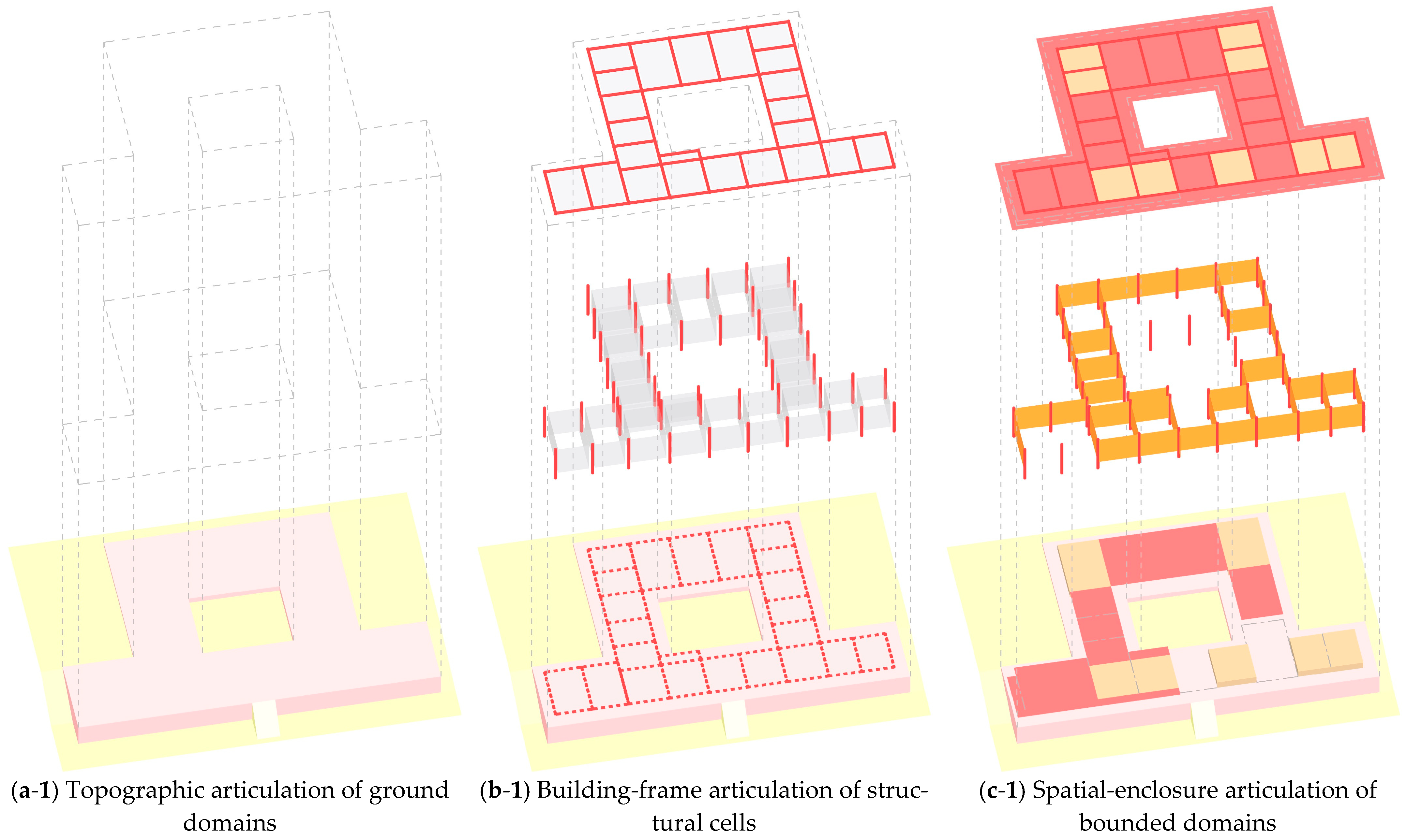
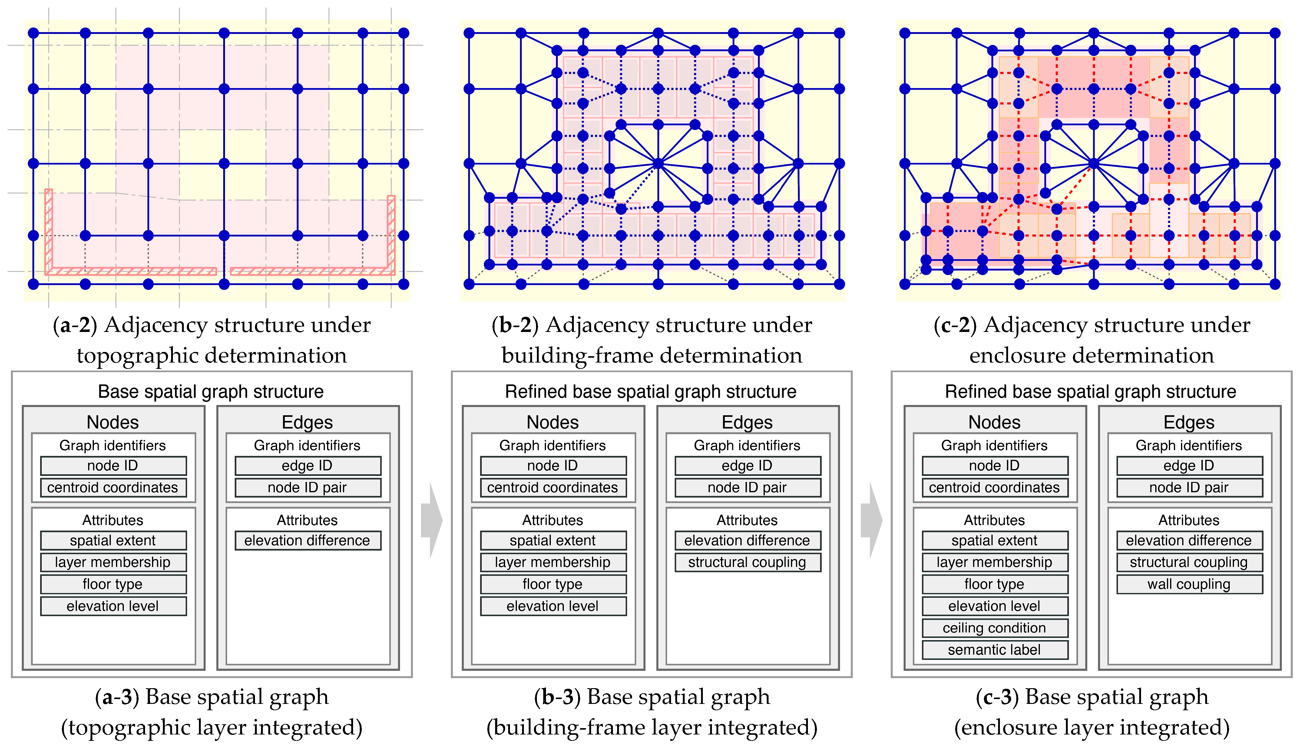
Figure 9 illustrates this process. The adjacency structure emerges progressively through topographic, structural, and enclosure conditions. Through cumulative incorporation of articulation condition attributes, a unified topological structure is established. At this stage, relational boundary attributes are not yet encoded; the graph records structural adjacency and articulation condition attributes only.
The resulting structure is termed the base spatial graph. It preserves all articulated spatial objects as nodes and all boundary correspondences as edges. Articulation condition attributes remain explicitly represented, ensuring traceability to articulated structural determination. No new nodes or edges are introduced during graph structuring.
Importantly, the base spatial graph does not yet resolve admissible boundary modes. Certain edges may remain mode-undetermined where articulation conditions do not uniquely imply relational activation. The graph records structural correspondence without performing relational selection.
Spatial graph structuring therefore translates articulated spatial entities into a formally organized topological structure while preserving structural determination. The base spatial graph constitutes the maximal topological structure implied by layered spatial articulation. Subsequent graph-domain operations act upon this determined structure without altering the articulated domain from which it is derived.

3.3.2. Executed Spatial Graph Structuring

Figure 10 demonstrates the execution of spatial graph structuring using the reference case introduced earlier. Figure 10(a-1)–(c-1) present spatial objects articulated across successive layers—topographic substrate, building frame, and spatial enclosure. Figure 10(a-2)–(c-2) show the cumulative development of the adjacency structure derived from these articulated spatial objects.
At this stage, adjacency is established solely on the basis of shared boundary correspondences. When two articulated spatial objects share a boundary segment, this correspondence is abstracted as an edge in the emerging topological structure. Adjacency therefore records structural boundary correspondence rather than admissible boundary-mode activation.
In the topographic substrate layer, elevation differences and discontinuities condition potential correspondences but do not eliminate them. Where significant level differences occur, edges are retained as structurally valid correspondences. Topographic discontinuity does not negate boundary correspondence; it prevents formation conditions from uniquely determining admissible boundary modes.
In the building frame layer, modular bays are articulated according to framing logic. Structural adjacency reflects shared frame-defined boundaries. However, frame continuity alone does not determine relational admissibility. Adjacency at this stage expresses structural contiguity rather than accessibility or open-air continuity.
In the spatial enclosure layer, enclosed and partially enclosed extents are articulated as spatial objects. Shared enclosure surfaces generate additional boundary correspondences. Yet the presence of an enclosure surface does not itself specify admissible boundary-mode combinations. The adjacency structure records enclosure correspondence without encoding relational modes.
Across Figure 10(a-2)–(c-2), these adjacency structures accumulate into a unified topological structure. All articulated spatial objects are preserved as nodes, and all admissible boundary correspondences are preserved as edges. No relational boundary modes are yet assigned.
The result of this process is the structurally determined base spatial graph at the topological level. It records:
  • the full node set determined by layered spatial articulation,
  • the complete edge set derived from shared boundary correspondences,
  • articulation condition attributes associated with nodes and edges.
Relational admissibility remains unspecified at this stage. Certain edges may admit multiple admissible boundary-mode combinations, but no relational activation or constraint has yet been applied.
Spatial graph structuring therefore consolidates articulated spatial objects into a structurally complete topological structure. It preserves structural determination achieved through layered articulation while postponing relational specification to subsequent graph-domain operations.

3.3.3. Edge-Level Encoding and Completion of the Base Spatial Graph

Spatial graph structuring produces a topological structure in which articulated spatial objects are represented as nodes and shared boundary correspondences as edges. The base spatial graph is completed through the encoding of relational boundary attributes at the edge level.
Node attributes are inherited directly from articulated spatial objects, preserving referential continuity with plan-level structural determination. These attributes anchor each node to the spatial object from which it was derived and maintain traceability to articulated formation conditions.
Edge attributes are encoded from relational boundary objects articulated in the relational boundary layer. When a relational boundary object corresponds to a boundary relation between two spatial objects, its articulation condition attributes and admissible boundary mode combinations are assigned to the corresponding edge. When no relational boundary object is articulated for a given boundary correspondence, the edge retains its articulation condition attributes while relational modes remain formally unspecified.
Through this encoding step, the adjacency structure becomes a fully specified base spatial graph. The node set and edge set established during spatial graph structuring are preserved, while relational boundary information is attached at the edge level.
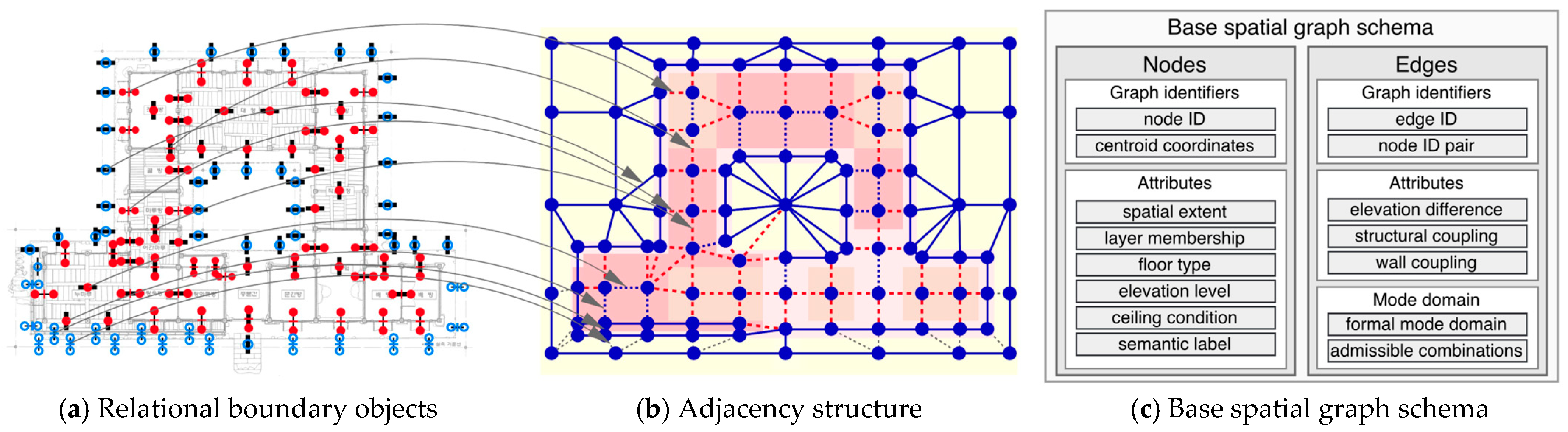
Figure 11 summarizes this process. Relational boundary objects are encoded into the developed adjacency structure, yielding the completed base spatial graph.
At this stage, the graph contains:
  • a structurally determined topological structure,
  • node-level articulation condition attributes,
  • edge-level articulation condition attributes,
  • admissible relational boundary-mode combinations.
The base spatial graph thus represents the maximal relational structure implied by layered spatial articulation at the level of structural determination. Subsequent graph-domain operations operate on this determined structure while preserving the articulated spatial domain from which it originates.

4. Base Spatial Graph and Graph-Domain Operations

Graph representations are commonly defined using a node–edge formulation, where a graph G = V , E consists of nodes and edges [29]. In spatial analysis, graph-based models such as space syntax and cell-based representations (e.g., IndoorGML) operate on predefined spatial units and assign relations between them.
In this study, the base spatial graph is constructed from articulated spatial objects and their boundary correspondences, as established in Section 3. Each edge is associated with a set of admissible relational modes derived from articulation conditions, defining a local relational state space. The graph therefore encodes a structured space of possible relations at the plan level, rather than a single fixed configuration.
On this basis, graph-domain operations act on the base spatial graph across three levels—structural transformation, semantic annotation, and display mapping—providing a framework for generating derived graphs from a common articulation.

4.1. Base Spatial Graph

This subsection formally defines the base spatial graph and its induced relational domain, followed by an illustrative instantiation.

4.1.1. Structural Definition

Let the structural graph be defined as
G s t r u c t u r e = ( V , E )
where V denotes the finite set of articulated spatial objects and E V × V denotes the finite set of admissible boundary correspondences derived from articulation. Edges are treated as undirected.
Articulation fixes V and E , thereby determining the structural topology of the graph.

4.1.2. Attribute and Mode Structure

The base spatial graph extends structural topology by incorporating articulation condition attributes and admissible mode combination sets:
G b a s e = ( V , E , A , C )
where A = { A v , A e } denotes node-level and edge-level articulation condition attributes, and C = { C e } assigns to each edge e E a set C e of admissible relational modes.
Each C e is defined as a subset of a relational domain D , which enumerates all definable boundary-mode combinations. While D is conceptually open, C e records only those combinations permitted under articulated boundary conditions.
Each edge thus defines a local relational state space through its admissible mode set C e , allowing relational variability to be explicitly represented within the graph structure.
Although node-level admissible mode sets C v   may be defined in principle, the present study treats relational variability as edge-centered. Node-level variability is not activated in the current analytical framework.

4.1.3. Induced Relational Scope

The relational scope induced by the base spatial graph is
M G base = e E C e
where each element of M ( G b a s e ) corresponds to a relational assignment obtained by selecting one admissible mode from each C e .
The size of this relational scope is
M G base = e E C e
The topology V , E is fixed by articulation, while relational admissibility varies within the edge-level admissible mode sets C e . The graph therefore encodes a structured space of admissible relational configurations rather than a single determined state.

4.1.4. Reference Case Instantiation

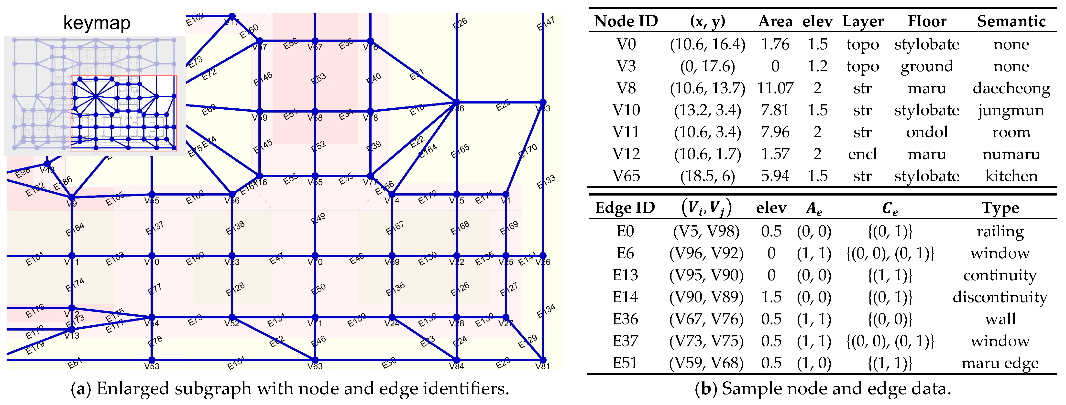
The formal structure defined above is instantiated using the reference case introduced in Section 3. The base spatial graph is shown in Figure 12.
A subset of node and edge attributes is shown alongside the graph. For each selected edge, articulation condition attributes A e and admissible mode combination sets C e are explicitly recorded. In this study, C e is defined over two relational components, Accessibility and OpenAir, forming a finite set of admissible relational mode tuples.
In the reference case, 162 edges satisfy | C e | = 1 , and 41 edges satisfy | C e | = 2 . According to Equation (4), the induced relational scope is | M ( G b a s e ) | = 2 41 2.20 × 10 12 .
This result shows that relational admissibility is finite yet combinatorially extensive within a fixed structural topology.

4.2. Graph-Domain Operations

Graph-domain operations act on the base spatial graph, defined as a fixed topology ( V , E ) together with a finite induced relational domain M ( G b a s e ) . These operations act on the structure to generate derived graphs.
All operations take the form
O : G G
where G is an input graph and G is the resulting graph after the operation. Operations are applied to an already articulated structure and do not introduce new articulated elements; any structural extension would require renewed articulation.
Operations are distinguished by their effect on graph topology. If both V and E remain unchanged, the operation is topology-preserving; if either change, the operation is topology-altering.
Within this framework, three types of operations are defined:
  • Structural transformations (T) modifies graph topology by altering the node set, the edge set, or both.
  • Semantic annotations (S) preserves topology and operates on the relational layer defined by admissible mode combination sets Ce, introducing annotation without modifying structural identity.
  • Display mapping (D) assigns display attributes to the graph, specifying how structural or semantic properties are rendered without altering topology or admissible mode sets.
These operations act on different components and levels of the graph and may be applied independently or in sequence. Structural transformation precedes semantic annotation, and display mapping operates on the resulting graph state.
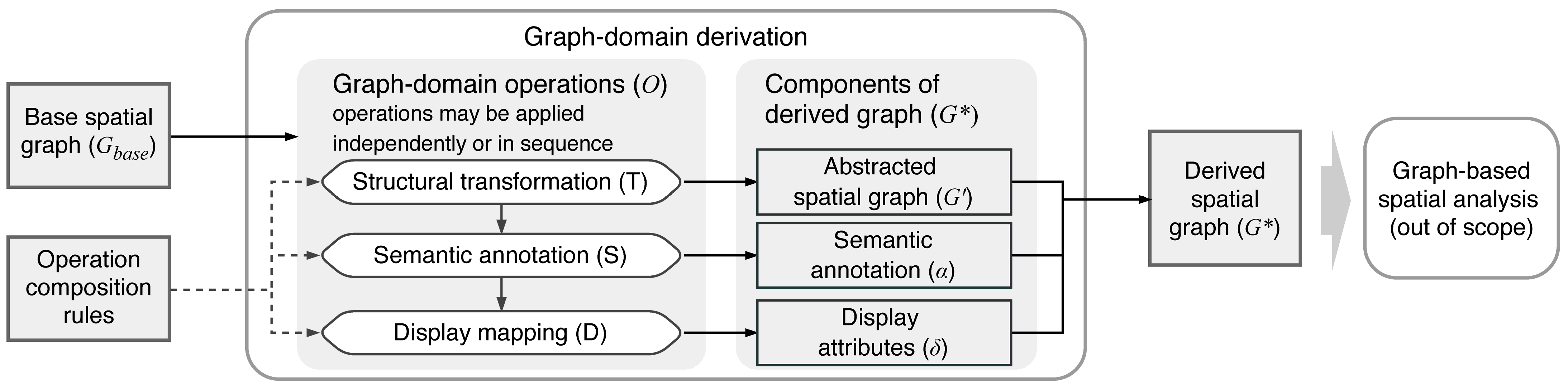
The overall structure of graph-domain derivation is illustrated in Figure 13.
Figure 13 illustrates the structure of graph-domain derivation. The base spatial graph serves as input, while operation composition rules determine how operations are selected and combined. Structural transformation (T), semantic annotation (S), and display mapping (D) act on different components of the graph, producing modified topology V , E , annotation layers α , and display attributes δ .
These outputs jointly define the derived spatial graph G * , incorporating structural, semantic, and display-level modifications. The diagram also indicates that operations may be applied independently or sequentially, and that their ordering affects the resulting graph state.

4.3. Structural Transformation

Structural transformation defines topology-altering operations within the graph-domain framework. It modifies structural identity by changing the node set V , the edge set E , or both.

4.3.1. Structural Transformation Definition

Let G s t r u c t u r e = ( V , E ) denote the structural topology of the base spatial graph.
A structural transformation is defined as
T : G s t r u c t u r e G s t r u c t u r e
where G s t r u c t u r e = ( V , E ) and either V V or E E .
Structural transformation redefines topology by reconfiguring, merging, contracting, or eliminating structural elements under explicitly declared rules.

4.3.2. Structural Transformation Mechanism

Structural transformation operates through rule sets composed of two components: topology rules and attribute aggregation rules.
Topology rules determine node merging, edge contraction or elimination, and adjacency reconfiguration. Attribute aggregation rules specify how node and edge attributes are inherited, combined, or reassigned.
Node-level and edge-level transformations are coupled. Changes in node identity induce corresponding changes in incident edges, requiring coordinated rule-based modification of the graph.

4.3.3. Structural Consequence

Structural transformation produces a new structural identity. Subsequent operations refer to the transformed graph G .
Structural transformation is generally information-reducing. When structural distinctions are collapsed without explicit trace retention, the transformation becomes irreversible.
Transformation operates within the articulated domain. Structural elements are reorganized or condensed, while articulation remains the source of structural generation.

4.3.4. Structural Transformations and Abstraction Levels

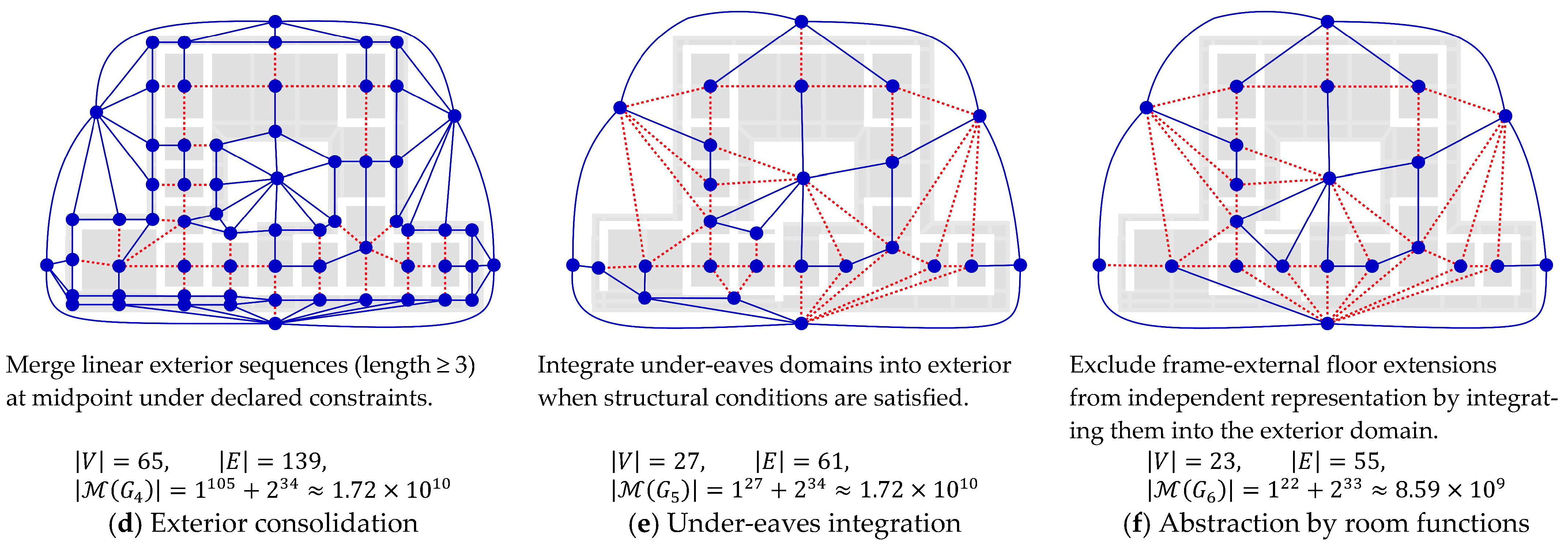
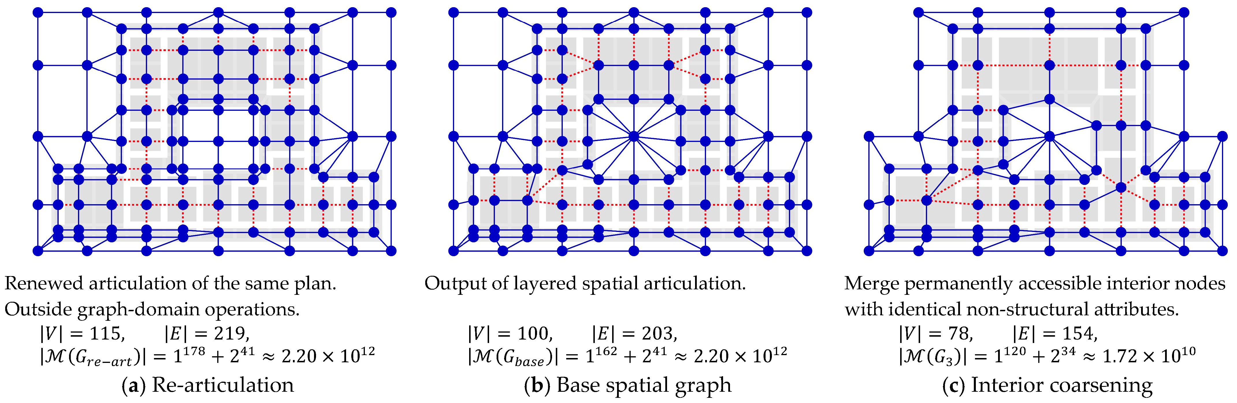
The reference case illustrates how multiple abstraction levels are derived from a common articulated structure. Figure 14 presents six graph forms. Graph (b) is the base spatial graph. Graphs (c)–(f) result from successive topology-altering transformations under declared rules, each reducing structural resolution by condensing articulated distinctions.
Graph (a) corresponds to renewed articulation rather than graph-domain transformation. It represents a different articulation regime and is not derived from the base graph through transformation.
For each graph, V , E , and M G are reported in Figure 14, quantifying the structural effects of transformation.
Across the panel, three principles are observed: topology changes only under explicitly defined rules; transformations are non-expansive within the articulated domain, and successive abstraction is irreversible without renewed articulation.

4.4. Semantic Annotation

Semantic annotation constitutes the first topology-preserving operation layer within this framework.

4.4.1. Semantic Annotation Definition

Semantic annotation operates on the fixed graph structure and introduces an annotation layer that specifies relational activation.
A semantic annotation is defined as a topology-preserving operation of the form
S : G G ( α )
where the input graph is G = ( V , E , A , C ) and the resulting graph is
G ( α ) = ( V , E , A , C , α )
The operation preserves structural topology V , E , articulation condition attributes A , and admissible mode combination sets C , and introduces only an annotation layer α .
The annotation layer is defined as
α = α m α c
where α m denotes the mode-assignment annotation set and α c denotes the attribute-constraint annotation set.

4.4.2. Mode Assignment Annotation

For each edge e E , let C e denote its admissible mode combination set.
Mode assignment selects one admissible combination per edge:
m e E C e
The assignment m produces a globally consistent relational configuration and is recorded as a mode-assignment annotation α m , yielding annotated graph:
G ( α m ) = ( V , E , A , C , α m )
Mode assignment specifies an active relational configuration while preserving admissible mode sets and structural topology.

4.4.3. Attribute Constraint Annotation

Attribute constraint introduces a constraint annotation layer α c that determines which elements are active under specified conditions.
Formally, α c is defined as an activation predicate over V , E , A , C . The annotated graph is written as
G ( α c ) = ( V , E , A , C , α c )
Nodes, edges, and admissible mode combination sets remain structurally defined, while activation is restricted by the constraint layer.

4.4.4. Structural Invariance of Semantic Operations

Both mode assignment and attribute constraint preserve structural topology ( V , E ) , articulation condition attributes A , and admissible mode combination sets C . Only the annotation layer α is modified.
Semantic annotation operates on relational activation, leaving relational possibility and structural identity unchanged.

4.4.5. Semantic Annotation Demonstration

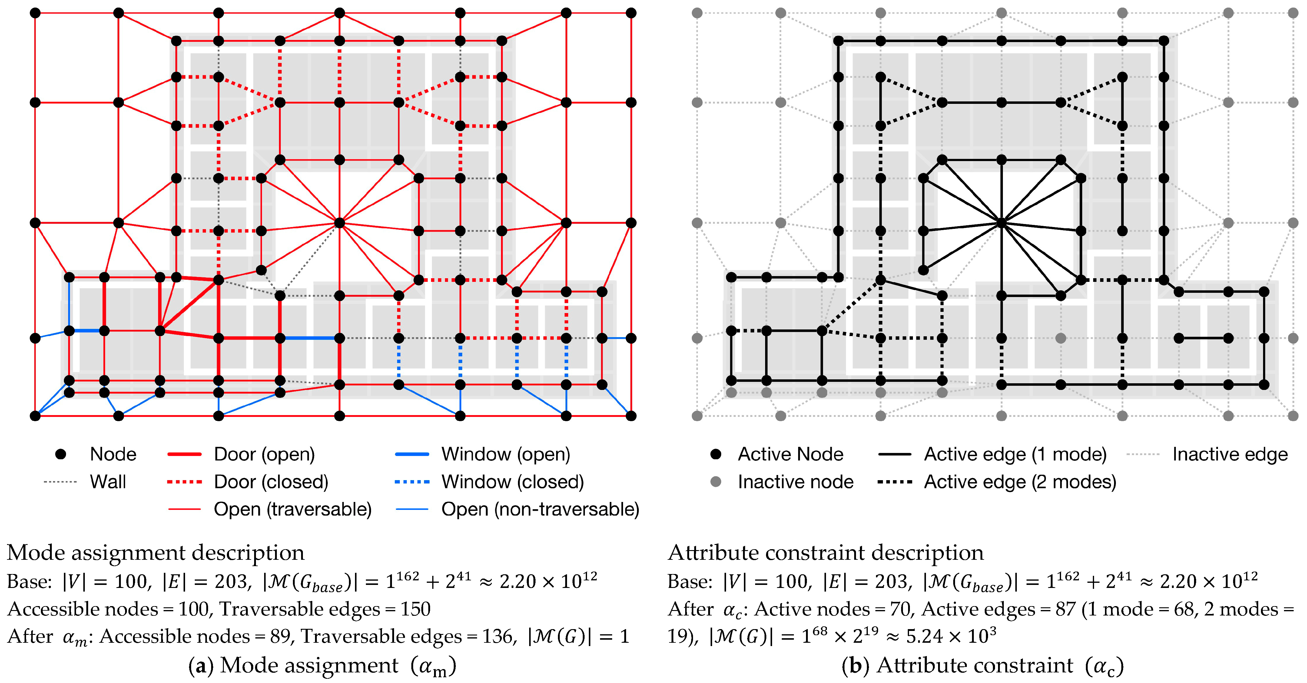
The reference case illustrates mode assignment ( α m ) and attribute constraint ( α c ).
Figure 15a shows mode assignment, where one admissible mode is selected per edge, yielding a single relational configuration.
Figure 15b shows attribute constraint, where nodes and edges are activated under specified conditions. The resulting graph retains topology while restricting active elements.

4.5. Display Mapping

Display mapping defines the presentation layer of the spatial graph. It assigns display attributes that render structural and relational properties perceptually interpretable.

4.5.1. Display Mapping Definition

Let G = ( V , E , A , C ) denote a spatial graph determined by articulation and preceding graph-domain operations.
A display mapping is defined as
D : G G δ
where the resulting graph is
G ( δ ) = ( V , E , A , C , δ )
The operation preserves structural topology ( V , E ) , articulation condition attributes A , and admissible mode combination sets C , and introduces only a display attribute layer δ .
The layer δ specifies visual properties assigned to graph elements and controls perceptual representation without altering structural or relational content.

4.5.2. Display Mapping Mechanism

Display mapping consists of explicit rules that assign visual properties to graph elements based on structural or relational attributes.
Node-level attributes may determine properties such as size, color, or pattern. For example, spatial extent may determine node size, semantic category may determine color, and elevation may define a continuous color gradient.
Edge-level attributes may determine visual emphasis, including thickness, color, or style. Accessibility may control edge thickness, elevation difference may determine color, and articulation condition type may determine style.
Display rules may also define visibility conditions. Elements may be suppressed under specified criteria while remaining part of the graph. The layer δ therefore controls perceptual emphasis rather than structural modification.

4.5.3. Operation Order and Composition

Graph-domain operations may be composed sequentially. Let T structural transformation, S denote semantic annotation, and D display mapping.
In the most general case, a graph resulting from composed operations is written as
G * = ( V , E , A , C , α , δ )
where ( V , E ) reflect structural transformation (if applied), A , C preserve articulation condition attributes and admissible mode sets, α denotes semantic annotation layers, and δ denotes display attributes.
In practice, display mapping is applied after structural transformation or semantic annotation. The principal compositions are
D S and D T
In general, composition across operation categories is not commutative:
D   T   T   D ,   D   S   S   D
Display mapping is idempotent under identical input and rule sets. Reapplication of the same mapping does not alter topology, relational admissibility, or annotation layers.

4.5.4. Display Mapping Demonstration

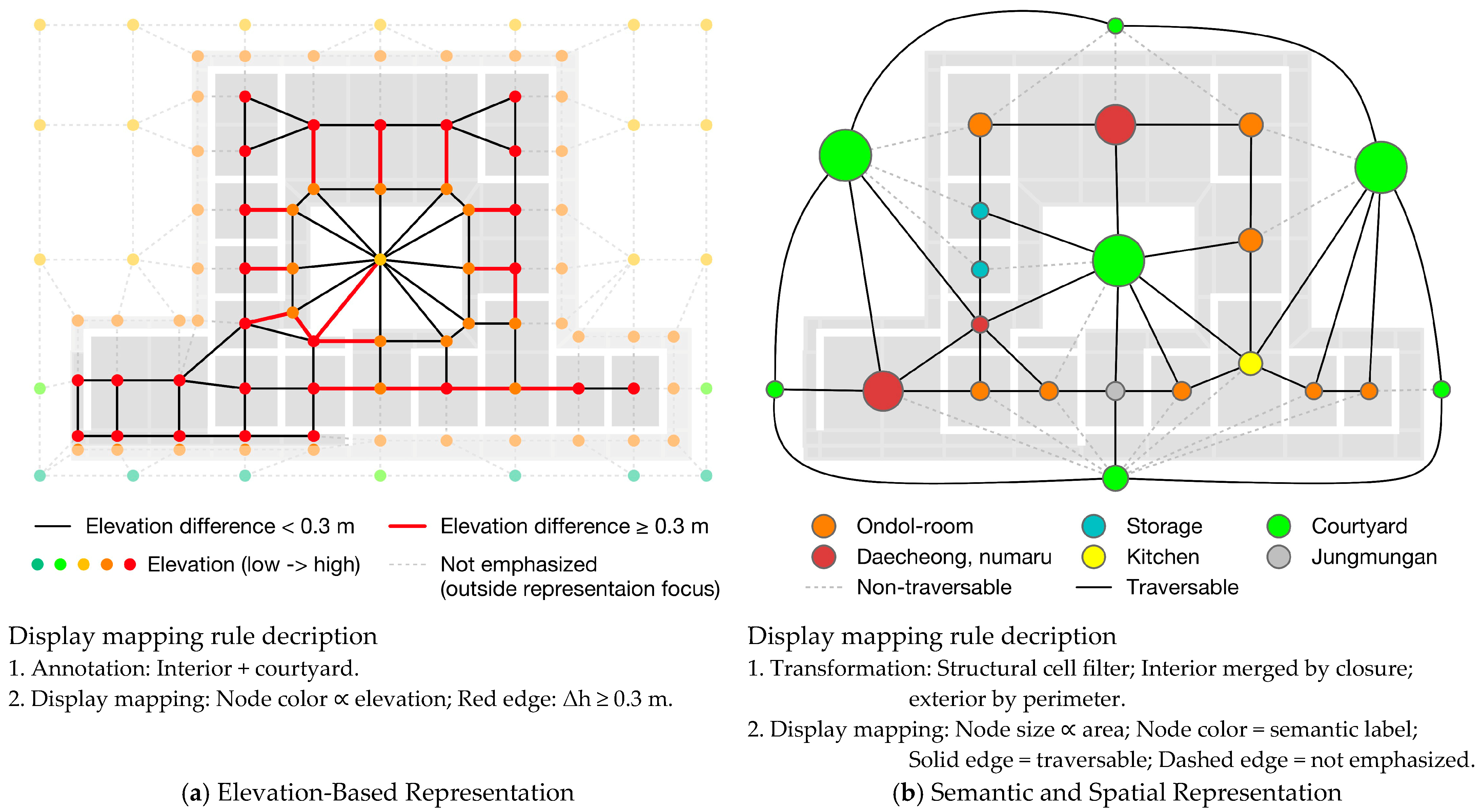
Figure 16 illustrates two display mappings applied to the reference case under different operation orders.
Figure 16a corresponds to the composition D S . Semantic annotation is first applied, followed by display mapping that assigns node color based on elevation and highlights edges with elevation difference Δ h 0.3 m .
Figure 16b corresponds to the composition D T . Structural transformation is first applied to obtain a reduced graph, followed by display mapping that assigns node size and color and emphasizes traversable edges.
In both cases, display mapping reorganizes perceptual structure while preserving structural identity. Differences between panels result from preceding operations rather than display mapping itself.

5. Discussion

This study formalizes the structural stage that precedes relational abstraction in graph-based spatial analysis. It specifies how spatial units and boundary correspondences become analytically determinate prior to the application of relational measures. In doing so, it establishes the structural conditions under which existing analytical methods operate.

5.1. Structural Determination Precedes Relational Abstraction

Graph-based spatial analysis typically operates on spatial units and boundary correspondences treated as given. Approaches such as space syntax [1,2] and cell-based representations (e.g., IndoorGML) [7,8] construct relational measures on predefined partitions, within which connectivity and accessibility are evaluated. In these approaches, spatial units are typically defined through enclosure or partition-based criteria, which do not account for structurally heterogeneous conditions. As a result, the articulation of spatial units remains implicit, limiting the analytical consistency of relational abstraction.
Beyond these approaches, existing studies have addressed spatial structure at different levels, but have not explicitly formalized the formation of spatial units. Conceptual and partition-based analyses of spatial configuration [11,19] describe spatial structure without treating the formation of spatial units as an explicit analytical procedure.
To address this shared limitation, this study formalizes the conditions under which spatial units and boundary correspondences become analytically determinate. Layered spatial articulation stabilizes heterogeneous determinants—topographic substrate, structural frame, enclosure, and boundary devices—as spatial objects, which are then organized into a base spatial graph.
The base spatial graph represents the structural outcome of this process. Each edge is associated with a set of admissible relational modes, defining a relational configuration space. This formulation specifies both the graph structure and the admissible configurations over that structure, shifting graph-based analysis from operating on given units to operating on explicitly determined structural conditions. Consequently, ambiguity in spatial unit definition is reduced and consistency in relational analysis is improved. This resolves the issue identified in the Introduction, namely the under-specification of spatial unit formation in existing graph-based approaches.

5.2. Analytical Coherence and Structural Grounding

The framework defines a directional structure. Articulation determines spatial objects and boundary correspondences; graph structuring consolidates these into a base spatial graph; graph-domain operations act within that determined structure. This order reflects the dependency of relational abstraction on prior structural determination.
Structural transformation reorganizes topology within the articulated domain. Structural reduction is therefore generally irreversible, as collapsed distinctions cannot be reconstructed without additional information. By specifying criteria for spatial object determination, the framework supports reproducibility and comparability across analyses.
This directional structure aligns with prior discussions on spatial organization and representation in architectural theory [1,10], while extending them by explicitly formalizing the structural determination stage within graph-based spatial analysis.
Descriptive accounts of architectural space based on geometric and spatial principles [18] do not address how such elements are analytically articulated into determinate spatial units. This limitation reflects the absence of an explicit structural determination stage. The present study extends this line of inquiry by formalizing the structural conditions under which spatial units are constituted.

5.3. Structural Consequence and Analytical Compatibility

This framework differs from existing graph-based approaches such as space syntax [1,2] and IndoorGML [7,8] by formalizing the structural preconditions of spatial units, whereas existing approaches operate on predefined partitions. In these approaches, the formation of spatial units is typically treated as implicit, limiting the analytical transparency of relational abstraction.
The framework introduces a prior structural stage to existing graph-based approaches. Configurational metrics, simulation techniques, and connectivity analyses may be applied to the base spatial graph without contradiction. The contribution lies in establishing explicit structural determination as a prerequisite for graph-based analysis, rather than an implicit assumption.
The framework applies across diverse architectural contexts in which spatial units and boundary correspondences require explicit structural determination, including contemporary building plans where structural, enclosure, and circulation systems do not coincide.
Once articulation is formalized and admissible boundary correspondences are encoded, a determinate graph domain is established. Within that domain, relational abstraction remains valid while operating on explicitly determined structural conditions.

6. Conclusions

The study establishes the structural stage preceding relational abstraction in graph-based spatial analysis. By formalizing layered spatial articulation at the plan level, it renders spatial objects and admissible boundary correspondences analytically determinate prior to graph construction. The base spatial graph does not impose relational structure arbitrarily; it reorganizes articulated entities into a fixed topological structure, in which edges encode admissible relational mode combinations.
The analysis establishes three structural conditions. First, relational abstraction depends upon prior spatial object determination. Second, adjacency does not entail connectivity; connectivity is constructed through declared boundary correspondences and admissible relational modes. Third, graph-domain operations are non-expansive within the articulated domain. Structural transformation reorganizes topology, while articulation remains the source of structural generation.
The present study is limited to the formalization of a methodological framework and does not aim at empirical generalization across multiple cases. While the framework enables the construction of base spatial graphs under explicitly defined structural conditions, the mere generation of such graphs does not by itself resolve the analytical challenges of spatial analysis. A further limitation lies in the need to situate the resulting graph structures within specific analytical contexts in which they can support meaningful spatial analysis and interpretation. Future work may therefore focus on the development of analytical procedures and application scenarios through which the proposed framework can support concrete analytical and interpretive tasks.

Author Contributions

Conceptualization, D.L.; methodology, D.L.; software, D.L.; validation, D.L.; formal analysis, D.L.; investigation, D.L.; resources, D.L.; data curation, D.L.; writing—original draft preparation, D.L.; writing—review and editing, D.L. and J.Y.; visualization, D.L.; supervision, J.Y.; project administration, J.Y.; funding acquisition, J.Y. All authors have read and agreed to the published version of the manuscript.

Funding

This research was supported by the National Research Foundation of Korea (NRF) grant funded by the Korea government (MSIT) (No. RS-2024-00344506).

Data Availability Statement

The original contributions presented in this study are included in the article. Further inquiries can be directed to the corresponding authors.

Conflicts of Interest

The authors declare no conflicts of interest.

References

  1. Hillier, B.; Hanson, J. The Social Logic of Space; Cambridge University Press: Cambridge, UK, 1984; ISBN 978-0-521-36784-4. [Google Scholar]
  2. Hillier, B. Space Is the Machine: A Configurational Theory of Architecture; Electronic; Space Syntax: London, UK, 2007; ISBN 978-0-9556224-0-3. [Google Scholar]
  3. Choi, J.; Kim, M.; Byun, N. Quantitative Analysis on the Spatial Configuration of Korean Apartment Complexes. J. Asian Archit. Build. Eng. 2013, 12, 277–284. [Google Scholar] [CrossRef] [Scilit]
  4. Kim, J.; Kwak, D. Extraction of Spatial Genetic Characteristics and Analysis of 1930s Korean Urban Hanok Based on Application of Space Syntax. J. Asian Archit. Build. Eng. 2022, 21, 197–210. [Google Scholar] [CrossRef] [Scilit]
  5. Kim, J. The Issue of Carrier Space and the Spatial Characteristics of Edo Middle-Lower Samurai Residences from a Space Syntax Perspective: Reinterpreting Spatial Evolution in Modern Japanese Urban Housing. J. Asian Archit. Build. Eng. 2025. early access. [Google Scholar] [CrossRef] [Scilit]
  6. Li, K.J.; Lee, J.Y. Basic Concepts of Indoor Spatial Information Candidate Standard IndoorGML and its Applications. J. Korea Spat. Inf. Soc. 2013, 21, 1–10. [Google Scholar] [CrossRef] [Scilit]
  7. OGC. OGC® INDOORGML, version 1.1; 19-011R4; Open Geospatial Consortium: Arlington, VA, USA, 2020.
  8. OGC. OGC IndoorGML 2.0 Part 1—Conceptual Model, version 2.0; 22-045r5; Open Geospatial Consortium: Arlington, VA, USA, 2025.
  9. Shekhar, S.; Xiong, H.; Zhou, X. (Eds.) Encyclopedia of GIS; Springer International Publishing: Cham, Switzerland, 2017; ISBN 978-3-319-17884-4. [Google Scholar]
  10. March, L.; Steadman, P. The Geometry of Environment: An Introduction to Spatial Organization in Design, 1st ed.; Routledge: London, UK, 2020; ISBN 978-1-000-69111-5. [Google Scholar]
  11. Peponis, J.; Wineman, J.; Rashid, M.; Kim, S.H.; Bafna, S. On the Description of Shape and Spatial Configuration inside Buildings: Convex Partitions and Their Local Properties. Environ. Plan. B Plan. Des. 1997, 24, 761–781. [Google Scholar] [CrossRef] [Scilit]
  12. Gimenez, L.; Robert, S.; Suard, F.; Zreik, K. Automatic Reconstruction of 3D Building Models from Scanned 2D Floor Plans. Autom. Constr. 2016, 63, 48–56. [Google Scholar] [CrossRef] [Scilit]
  13. Knechtel, J.; Rottmann, P.; Haunert, J.-H.; Dehbi, Y. Semantic Floorplan Segmentation Using Self-Constructing Graph Networks. Autom. Constr. 2024, 166, 105649. [Google Scholar] [CrossRef] [Scilit]
  14. Lu, Z.; Wang, T.; Guo, J.; Meng, W.; Xiao, J.; Zhang, W.; Zhang, X. Data-Driven Floor Plan Understanding in Rural Residential Buildings via Deep Recognition. Inf. Sci. 2021, 567, 58–74. [Google Scholar] [CrossRef] [Scilit]
  15. Lee, J.H.; Ostwald, M.J.; Zhou, L. Socio-Spatial Experience in Space Syntax Research: A PRISMA-Compliant Review. Buildings 2023, 13, 644. [Google Scholar] [CrossRef] [Scilit]
  16. Netto, V.M. ‘What Is Space Syntax Not?’ Reflections on Space Syntax as Sociospatial Theory. URBAN Des. Int. 2016, 21, 25–40. [Google Scholar] [CrossRef] [Scilit]
  17. Alexander, C.; Ishikawa, S.; Silverstein, M.; Jacobson, M. A Pattern Language: Towns, Buildings, Construction; Center for Environmental Structure Series; Oxford University Press: New York, NY, USA, 1977; ISBN 978-0-19-501919-3. [Google Scholar]
  18. Ching, F.D.K. Architecture: Form, Space, & Order, 4th ed.; Wiley: Hoboken, NJ, USA, 2014; ISBN 978-1-118-74513-7. [Google Scholar]
  19. Björk, B.-C. A Conceptual Model of Spaces, Space Boundaries and Enclosing Structures. Autom. Constr. 1992, 1, 193–214. [Google Scholar] [CrossRef] [Scilit]
  20. Fletcher, B.S. (Ed.) Sir Banister Fletcher’s a History of Architecture; Architectural Press: Oxford, UK, 1996. [Google Scholar]
  21. Perrault, C. Les Dix Livres D’architecture de Vitruve, 2nd ed.; Chez Jean Baptiste Coignard: Paris, France, 1684. [Google Scholar]
  22. Laugier, M.-A. Essai sur L’architecture, 2nd ed.; Chez Duchesne: Paris, France, 1755. [Google Scholar]
  23. Liang, S. A Pictorial History of Chinese Architecture: A Study of the Development of Its Structural System and the Evolution of Its Types; Fairbank, W., Ed.; MIT Press: Cambridge, MA, USA, 1984; ISBN 0-262-12103-4. [Google Scholar]
  24. Kim, D. Palaces of Korea; Korean Culture Series; Hollym International Corp: Elizabeth, NJ, USA, 2006; ISBN 978-1-56591-225-0. [Google Scholar]
  25. Kim, D. History of Korean Architecture; Tisher, G.A., Ed.; University of Kyonggi Press: Suwon-si, Republic of Korea, 2013; ISBN 978-89-86922-68-4. [Google Scholar]
  26. Cultural Heritage Administration of Korea. Gwangajeong (觀稼亭): Architectural Survey Report; Cultural Heritage Administration of Korea: Daejeon, Republic of Korea, 2001; p. 274. [Google Scholar]
  27. Seo, H.W.; Kim, Y. Dismantlement of Traditional Hanok Space and Emergence of Modern Hanok. J. Asian Archit. Build. Eng. 2022, 21, 173–186. [Google Scholar] [CrossRef] [Scilit]
  28. Mitchell, W.J. The Logic of Architecture: Design, Computation and Cognition, 6th ed.; MIT Press: Cambridge, MA, USA, 1998; ISBN 978-0-262-13238-1. [Google Scholar]
  29. Diestel, R. Graph Theory, 5th ed.; Graduate Texts in Mathematics; First Softcover Printing; Springer: Berlin/Heidelberg, Germany, 2018; ISBN 978-3-662-53621-6. [Google Scholar]

Figure 1. Implicit procedure of spatial object formation and graph abstraction in graph-based spatial analysis.
Buildings 16 01536 g001
Figure 2. Historically recognized architectural spaces: (a) Perrault’s primitive hut; (b) Laugier’s primitive hut; (c) Çatalhöyük; (d) Farnsworth House. Sources: (a) Les Dix livres d’architecture de Vitruve [21] (public domain); (b) Essai sur l’architecture [22] (public domain); (c) Çatalhöyük model image, Wikimedia Commons (public domain, photo by Sauber); (d) Farnsworth House photograph, U.S. Library of Congress (public domain, photo by Highsmith).
Buildings 16 01536 g002
Figure 3. Representative image set of the reference case (Gwangajeong): (a) site layout; (b) front-left view; (c) right elevation; (d) left exterior view; (e) rear view. Sources: (a) Map data © NGII of Korea via Naver Maps, adapted for illustrative purposes; (be) Korea Heritage Service, digital.khs.go.kr, used under KOGL Type 1 (Source Indication).
Buildings 16 01536 g003
Figure 4. Major spatial areas identified on the plan of Gwangajeong: (ac) wooden-floored halls and rooms facing the courtyard; (d) middle gate module; (e,f) interior spaces; (g) main heated room (ondol); (h) kitchen with hearths; (i) floorplan. Source: Korea Heritage Service, https://digital.khs.go.kr, used under KOGL Type 1 (Source Indication).
Buildings 16 01536 g004
Figure 5. Analytical structure of the methodological framework.
Buildings 16 01536 g005
Figure 6. Conceptual structure of the layered spatial articulation process.
Buildings 16 01536 g006
Figure 7. Layered spatial articulation process illustrating structural determination of spatial objects from plan-encoded information.
Buildings 16 01536 g007aBuildings 16 01536 g007b
Figure 8. Structured articulation across analytical layers, showing staged identification–derivation–composition and controlled inter-layer reference.
Buildings 16 01536 g008
Figure 9. Conceptual structure of base spatial graph structuring.
Buildings 16 01536 g009
Figure 10. Progressive determination of the base spatial graph prior to boundary-mode encoding: ((a-1)–(c-1)) articulated spatial objects; ((a-2)–(c-2)) cumulative adjacency; ((a-3)–(c-3)) incremental specification of the base spatial graph.
Buildings 16 01536 g010aBuildings 16 01536 g010b
Figure 11. Relational boundary encoding and completion of the base spatial graph: (a) articulated relational boundary objects; (b) adjacency structure prior to encoding; (c) base spatial graph after edge-level boundary-mode encoding.
Buildings 16 01536 g011
Figure 12. Base spatial graph instantiation for the reference case: (a) enlarged subgraph; (b) sample node and edge data showing articulation attributes and constrained mode domains.
Buildings 16 01536 g012
Figure 13. Graph-domain derivation framework.
Buildings 16 01536 g013
Figure 14. Structural transformations and abstraction levels of the base spatial graph: (a) re-articulation (outside graph domain); (b) base spatial graph; (ce): successive topology-altering transformations; (f) Integration of frame-external floor extension into exterior domain. V , E , M G are reported for each.
Buildings 16 01536 g014aBuildings 16 01536 g014b
Figure 15. Semantic annotation of the base spatial graph: (a) Mode assignment ( α m ) ; (b) Attribute constraint ( α c ) . In both cases, topology remains unchanged.
Buildings 16 01536 g015
Figure 16. Display mapping of the base spatial graph: (a) D S ; (b) D T .
Buildings 16 01536 g016
Table 1. Characteristics of Historically recognized architectural spaces.
CaseSpatial BasisRecognized SpacesEnclosure TypeAccess Mode
Perrault’s primitive hut (1684)Topographic enclosure beneath a roof structureEnclosed interior spaceFully enclosedAt ground level
Laugier’s primitive hut (1755)Exposed building frame under a roofSpace articulated by structural frameStructurally openGround level
Çatalhöyük
(c. 7300 BC)
Opaque enclosing shell defining interior and roof-level spatial domainsEnclosed interior cells; courtyard; roof-level spaceMixed (enclosed interior, open roof)Multi-level
(roof access)
Farnsworth House (1951)Elevated horizontal planes organized by a vertical building frameGlazed interior; terrace; elevated platformEnclosed (visually permeable)Elevated platform access
Table 2. Comparison of spatial conditions in major architectural spaces of Gwangajeong.
Spatial TypeUpper SurfaceFloor ConditionLateral EnclosureSpatial Domain CharacterAssociated Activities
Ondol roomCeilingOndolWallsClearly definedSleeping, living
DaecheongRoofWoodenOpen/variableMixed interior–exteriorStaying, passage
Side maruRoofWoodenOpenAttached/partialMulti-purpose
MarubangRoofWoodenWallsClearly definedStorage
KitchenRoofStylobateWallsSemi-exteriorCooking, heating
JungmunganRoofStylobatePartial (gate)Semi-exteriorPassage, buffering
Under-eavesEavesStylobateOpenDefined by upper surfacePassage
CourtyardNoneEarthNoneEnclosed exteriorMulti-purpose
Table 3. Relational boundary object classification by articulation conditions and mode domain.
Boundary Articulation ConditionsRelational Mode DomainAdmissible Mode CombinationsNotationExample
Topographic ConditionBuilding Frame CouplingLateral Enclosure CouplingAccessibility ModesOpen-Air Modes
leveltruetrue{0, 1}{0}{(0, 0), (1, 0)}=|=door
{0}{0, 1}{(0, 0), (0, 1)}-|-window
false{1}{1}{(1, 1)}==open bay
{0}{1}{(0, 1)}--railings
falsefalse{1}{1}{(1, 1)}==eave boundary
{0}{1}{(0, 1)}--railings
true{0, 1}{1}{(0, 1), (1, 1)}=|=main gate
discontinuousfalsefalse{0}{1}{(0, 1)}-|-retaining wall
* Notation: / denotes spatial objects (: building-frame coupled; : building-frame uncoupled); =/– denotes accessibility (= accessible; – not accessible but open-air possible); | denotes lateral enclosure coupling. Combinations encode admissible boundary modes.
Disclaimer/Publisher’s Note: The statements, opinions and data contained in all publications are solely those of the individual author(s) and contributor(s) and not of MDPI and/or the editor(s). MDPI and/or the editor(s) disclaim responsibility for any injury to people or property resulting from any ideas, methods, instructions or products referred to in the content.