3.1. Case Study Design
To identify the independent influence of key parameters on structural weight and lateral displacement control, this section first conducts single-variable optimization on a unified baseline model of a 300 m super-tall building with 6-degree seismic intensity and a lateral system consisting of two outrigger trusses and three belt trusses. Three parameters are taken in turn as the sole design variable: (1) the mega-column cross-sectional dimension
Z; (2) the member sections
of the outrigger and belt trusses; and (3) the vertical elevations
of the outrigger and belt trusses, while all other parameters are kept at their baseline values, as shown in
Table 1. In this manner, sensitivity curves of the objective functions corresponding to three strategies—“increasing or decreasing the mega-column size”, “reducing truss weight”, and “shifting the truss story levels”—can be directly obtained, thereby providing value ranges and reference information for the subsequent multi-variable collaborative optimization. In the present case study, the top and bottom chords of the outrigger truss were assigned the same cross section, denoted as R1; the web members of the outrigger truss and the belt truss were assigned the same cross section, denoted as R2; and the top and bottom chords of the belt truss were assigned the same cross section, denoted as R3. For member groups sharing the same cross section, the section sizes were discretely selected from the same predefined section library during the optimization process, as listed in
Table 2.
The multi-variable case studies were designed for building heights of 200 m and 300 m. For each height, optimal designs were obtained under design seismic intensity levels of 6-degree (0.05 g) and 8-degree (0.20 g), with two alternative outrigger–belt truss configurations: one outrigger truss plus two belt trusses and two outrigger trusses plus three belt trusses. Each case is denoted by an index triple (
), where i represents the building height (200 m or 300 m), j represents the seismic intensity level (6 or 8), and k represents the truss configuration, taking values of 1 + 2 (one outrigger truss and two belt trusses) or 2 + 3 (two outrigger trusses and three belt trusses). The detailed definitions of all cases are summarized in
Table 3. According to the provisions of the Load Code for the Design of Building Structures GB 50009–2012 [
23], the load conditions adopted in the analysis are specified in
Table 4. Unless otherwise stated, all parametric studies and optimization runs in
Section 3 adopted the baseline design inputs summarized in
Table 4, in order to ensure a consistent and fair comparison across different spans, story numbers, and member-size combinations.
3.2. Analysis of Single-Variable Optimization Results
Table 5 summarizes the optimization results when the truss member size
, the truss elevations
, and the mega-column cross-sectional dimension
Z are taken, respectively, as the sole design variable. The corresponding variations of the objective functions are shown in
Figure 1a–c.
Figure 1a,c presents the relationship between the total structural weight and the maximum inter-story drift ratio for the cases where only the truss positions and only the truss member sizes are treated as variables, respectively.
Figure 1b illustrates the influence of the mega-column cross-sectional dimension on both objective functions, giving the joint distribution of total weight and inter-story drift ratio and thereby revealing the trade-off between these two objectives.
The lateral performance is highly sensitive to adjustments in the truss elevations. As shown in
Figure 1a, when the three outrigger–belt truss stories are placed at approximately 0.40 H, 0.54 H, and 0.92 H, the maximum inter-story drift ratio of the structure is significantly reduced, indicating that the stories where the strengthening trusses are located can effectively modify the overall lateral deformation pattern. This also implies that the single-variable position optimization has already identified “high-probability intervals” that should be emphasized in the subsequent multi-variable search, and the collaborative optimization results presented later indeed converge further toward this height range.
The variation of the mega-column cross-sectional dimension exhibits a typical marginal-effect behavior. As illustrated by the blue curve in
Figure 1b, reducing the column size directly decreases the total structural weight; however, when the column dimension is reduced from 1.80 m to 1.40 m, the maximum inter-story drift ratio increases by about 53%, indicating that further reduction will soon be governed by deformation constraints and that a trade-off between weight reduction and seismic performance is required.
The red curve in
Figure 1c, which illustrates the joint distribution of truss dimensions versus total weight and drift ratio, confirms this trend: the total structural weight decreases only from 8.69 × 10
7 kg to 8.58 × 10
7 kg. A closer inspection of these points shows that when the total weight is reduced to 8.62 × 10
7 kg, the total structural weight decreases by 0.8%, whereas the maximum inter-story drift ratio increases by 4%. When the total weight is further reduced from 8.62 × 10
7 kg to the optimal value of 8.58 × 10
7 kg, the weight reduction is merely 0.5%, while the drift ratio increases by 8%. In other words, single-variable optimization can achieve a certain amount of weight reduction at the early stage without significantly compromising deformation performance, but at the later stage it exhibits “diminishing returns in weight reduction and increasing deformation penalty”, which is precisely the stage where multi-variable collaborative optimization becomes necessary.
To investigate the mutual interactions among the key variables, the mega-column cross-sectional dimensions, truss member sizes, and truss elevations were simultaneously treated as design variables, and their combined influence on the total structural weight and the maximum inter-story drift ratio was analyzed using the optimization framework described above. The corresponding optimal solutions for each model are summarized in
Table 6.
For the 200 m building under 6-degree seismic intensity, a comparison between cases and shows that in scheme , the chord members of the belt trusses and the column cross sections are slightly larger than those in in order to satisfy the lateral stiffness requirement. Although only one outrigger truss and two belt trusses are provided, a weighting factor of 7 is applied to steel members in the calculation of the equivalent total structural weight. Specifically, the steel weighting factor is defined as , where is the density ratio of steel to concrete, is the unit cost ratio of steel to concrete, and is a normalization coefficient used to control the contribution of the economic term. In this study, was adopted so that the cost-related term remained comparable in magnitude to the density-related term without dominating the equivalent weighting; accordingly, the steel members were assigned an equivalent weighting factor of 7 in the present design comparison. As a result, the reduction in the number of truss members offsets the effect of enlarged cross sections, and the equivalent total structural weight of becomes slightly lower than that of , while the maximum inter-story drift ratio still satisfies the control limit of 1/660. Therefore, for the 200 m, 6-degree design condition, the “1 outrigger + 2 belt trusses” configuration can be preferred, as it achieves better economy while maintaining acceptable deformation performance.
From the perspective of truss layout strategy, the comparison among cases , , and indicates that under 8-degree seismic intensity, the double-outrigger configuration (2 + 3) is more appropriate. When the maximum inter-story drift ratio is maintained at a similar level, the double-outrigger scheme can further reduce the total structural weight by providing more effective restraint to the exterior frame. For the 200 m building, when the configuration changes from 1 + 2 to 2 + 3, the exterior column cross sections can be reduced to about 59% of their original size, corresponding to a reduction of approximately 41%. This implies that adding one more outrigger–belt truss system allows “more lateral stiffness members” to be traded for “smaller vertical gravity-resisting members”.
The same set of cases also shows that when the seismic intensity level increases from 6-degree to 8-degree, the lower outrigger elevation shifts upward from about 0.40 H to about 0.46 H, and the mid-height belt truss is likewise moved upward, whereas the upper outrigger elevation decreases slightly so as to form a more reasonable force-transfer path in the upper region. This indicates that the optimal elevations of the strengthening stories are not fixed values, but tend to move upward as the seismic demand increases.
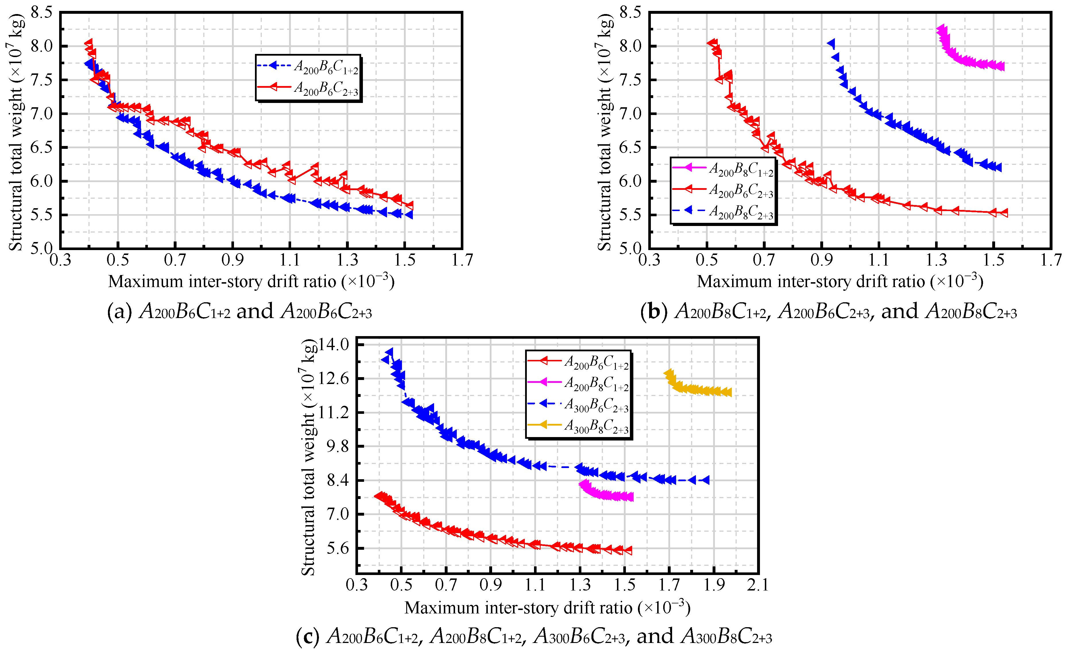
Figure 2 presents the relationship between the total structural weight and the maximum inter-story drift ratio for all cases. For the 6-degree structures, as the total weight is gradually reduced, the drift ratio increases monotonically. Once the total weight is reduced below a certain level, however, further weight reduction leads to a rapid deterioration in deformation control, and the overall optimization performance deteriorates, exhibiting a typical “boundary effect”. In the 8-degree cases, the curves lie much closer to the drift-limit lines, indicating that under higher seismic intensity, drift control becomes the dominant constraint. In this regime, the influence of weight reduction on the drift ratio is no longer linear: even a modest reduction in total weight may cause a pronounced increase in drift, and the sensitivity is significantly higher than in the 6-degree cases. The locally sawtooth-like scattered points in the figure mainly arise from the discrete combinations of structural members and the random sampling of design variables by the optimization algorithm; they are typical numerical features of discrete optimization problems and do not affect the assessment of the overall trends.
By further performing pairwise comparisons of the optimal results for cases and , as well as and , the following observations can be made. When the seismic intensity level is increased, the optimal elevations of the lower outrigger and the mid-height belt truss both shift upward, while the upper outrigger is slightly lowered, so as to enhance the constraint on the overall lateral displacement provided by the middle and lower parts of the structure.
In the 6-degree cases, the web members of the outrigger and belt trusses can preferentially adopt smaller sections (e.g., L5/L6), and the deformation performance still remains about 50% better than the code limit (e.g., an actual maximum inter-story drift ratio of 1/660 versus the limit of 1/500), leaving substantial room for economic optimization. In the 8-degree cases, however, due to the more stringent design constraints, the truss web members of the 300 m structure must be upgraded to larger sections such as L3/L4, effectively “sacrificing part of the economy” to secure sufficient stiffness. This represents an unavoidable trade-off for the combination of high seismic intensity and great building height.
A comparison of the four cases , , , and shows that the building height and the design seismic intensity jointly determine whether the optimization tends to be “economy-oriented” or “stiffness/drift-control-oriented”. For the 200 m structures, a relatively relaxed feasible region is available under both 6-degree and 8-degree seismic intensities: the cross sections of the trusses and columns can be selected within a wide range, and even after weight reduction, the maximum inter-story drift ratio still maintains a considerable margin with respect to the code limit. Therefore, at this height level, parameter tuning can be guided primarily by economic considerations.
When the height increases to 300 m, the situation changes markedly. On the one hand, the overall lateral deformation becomes more sensitive, and the feasible solutions generated by the genetic algorithm generally lie close to the drift-limit boundary. On the other hand, to maintain a reasonable lateral stiffness transfer path, a stronger configuration such as the double-outrigger plus three belt trusses (2 + 3) is required. Correspondingly, the member sizes increase systematically. Under 6-degree seismic intensity, the web members of the outrigger and belt trusses typically need to adopt L4–L5 sections, and the column cross-sectional dimensions must be controlled within approximately 1.15–2.05 m. Under 8-degree seismic intensity, to counteract the higher seismic demand, the truss web members must be upgraded to L3–L5, and the lower bound of the column dimension must be raised to around 2.55 m.
These observations indicate that for 300 m buildings—especially under 8-degree seismic conditions—the dominant optimization objective shifts from “maximizing weight reduction” to “satisfying drift control first and then pursuing economy”. In this regime, the elevations of the truss stories must be selected with greater precision; otherwise, it becomes difficult to obtain feasible solutions without significantly enlarging the column cross sections.
3.3. Comparative Analysis of Multi-Variable and Single-Variable Optimization
As summarized in
Table 7, all cases considered a 300 m super-tall building designed for 6-degree seismic intensity, with a lateral system comprising two outrigger trusses and three belt trusses. Comparing Case Z with Case
indicates that when only the column cross sections are optimized, the best solution under the single-variable strategy occurs at a column side length of 1.37 m. In contrast, the multi-variable collaborative optimization moderately increases the chord-member sections of the outrigger trusses and the web-member sections of all trusses, and slightly shifts upward the elevations of the mid-height belt truss and the upper outrigger truss. These coordinated adjustments enhance the lateral contribution of the truss system, thereby allowing a further reduction in column size and achieving a lower total structural weight.
Comparisons between Case and Case , as well as between Case and Case , show that optimizing either the truss member sections or the truss story levels alone can yield certain local improvements—even reaching the same truss section grades or truss elevations as those in the multi-variable optimum. However, due to the pronounced coupling among column cross sections, truss member sizes, and truss elevations, keeping the remaining variables at their baseline values limits the overall synergy; consequently, the resulting total structural weight remains higher than that achieved by the multi-variable collaborative optimization.
Moreover, comparing with indicates that the total structural weight increases by only 0.13%, whereas the maximum inter-story drift ratio decreases by approximately 36%. This suggests that, within a single-variable framework, adjusting the truss elevations is more effective than optimizing the truss member sizes. Although neither strategy leads to a substantial reduction in total weight, truss-elevation optimization can significantly improve drift control and thus enhance structural safety with essentially comparable economic efficiency.
When multi-variable collaborative optimization is adopted and the three degrees of freedom—truss member sizes, truss elevations, and column cross sections—are released simultaneously, the algorithm tends to “moderately increase the sizes of the key trusses and shift their elevations upward” so as to improve the overall lateral deformation pattern, thereby allowing the column side length to be further reduced to 1.15 m. In this case, the total structural weight is not only lower than the optimal values obtained from any single-variable strategy, but the maximum inter-story drift ratio also remains within the code limits. This indicates that for such highly coupled super-tall systems, the truss configuration and column dimensions must be considered in a unified optimization framework in order to achieve a more balanced trade-off between weight reduction and lateral/seismic performance, which in turn confirms the necessity of employing a multi-variable, multi-objective optimization approach.
To further clarify the necessity of multi-variable collaborative optimization for the strongly coupled outrigger–belt-truss–mega-column system,
Table 8 presents several representative feasible solutions selected from the multi-variable optimization results of A300B6C2 + 3 (Schemes 1–6). Scheme 6 was the best feasible solution obtained from the multi-variable optimization and was used as the optimal reference. In the following discussion, the weight reduction percentage is calculated in the standard form, i.e.,
, where
is the total structural weight of the comparison scheme and
is that of Scheme 6.
For the mega-column size, single-variable optimization yielded an optimal column side length of 1.37 m. Accordingly, Scheme 1 was selected from the multi-variable solution set with the same column size. Relative to Scheme 1, Scheme 6 achieved a weight reduction of approximately 6.5%, while the maximum inter-story drift ratio of Scheme 1 was about 1.2% lower. This indicates that a column size that appears optimal under fixed baseline assumptions for the other variables does not necessarily produce a globally preferable solution when truss sections and elevations are allowed to co-vary.
For truss member sizing, single-variable optimization identified L6 as the optimal section grade. Therefore, Schemes 2 and 3 were selected from the multi-variable solution set with truss sections equal to L6. Relative to Schemes 2 and 3, Scheme 6 achieved weight reductions of approximately 16.2% and 11.5%, respectively, while the maximum inter-story drift ratio was also lower in Scheme 6.
For truss elevations, single-variable optimization suggests optimal elevations of 120 m, 162 m, and 276 m. Accordingly, Schemes 4 and 5 were selected from the multi-variable solution set with these elevations. Relative to Schemes 4 and 5, Scheme 6 achieved weight reductions of approximately 15.0% and 18.4%, respectively. This further confirms that adopting single-variable optimal truss elevations alone, without simultaneous adjustment of column size and truss member sections, does not lead to a globally optimal weight–drift compromise.
Overall, the comparisons in
Table 8 provide direct evidence that mega-column size, truss member sizing, and strengthening-story elevations are strongly coupled. Single-variable optimization therefore produces conditional optima under fixed assumptions for the remaining variables, whereas globally competitive solutions require coordinated adjustments across multiple variables. From a structural-mechanism perspective, the outrigger and belt trusses act as “mega-beams” that provide effective lateral restraint to the exterior frame, redistribute internal forces among vertical members and mitigate deformation concentration, and offer lateral bracing to columns, thereby reducing their effective length. Consequently, optimizing any single parameter in isolation cannot simultaneously balance lateral stiffness allocation and gravity-system demand. These findings further support the advantage and necessity of multi-variable collaborative optimization for highly coupled super-tall building systems.