Article

Numerical Analysis of the Lateral Responses of Pile Foundations Under Overall and Progressive Scour Conditions


1
School of Civil Engineering, Hunan University of Science and Technology, Xiangtan 411201, China
2
Hunan Provincial Key Laboratory of Geotechnical Engineering for Stability Control and Health Monitoring, Xiangtan 411201, China
3
Hunan University of Science and Technology Engineering Testing Co., Ltd., Xiangtan 411201, China
*
Author to whom correspondence should be addressed.
Buildings 2026, 16(7), 1285; https://doi.org/10.3390/buildings16071285
Submission received: 15 February 2026 / Revised: 13 March 2026 / Accepted: 16 March 2026 / Published: 25 March 2026
(This article belongs to the Special Issue New Reinforcement Technologies Applied in Slope and Foundation)

Abstract

The pile foundations of hydraulic crossing structures are vulnerable to scour, which can significantly reduce bearing capacity and threaten structural safety. In existing studies, simplified assessment approaches have mainly been used, such as pre-defined scour holes or instantaneous scour, which cannot fully capture the progressive development of scour holes. In addition, there are limited systematic comparisons of the lateral responses of piles with different cross-sectional shapes under scour conditions. To address these issues, a series of finite element simulations were carried out in this study and the numerical model was validated against centrifuge test results. The “model change” technique was then used to simulate the progressive development of general scour. Circular and square piles with equal cross-sectional areas were considered under scour conditions, and the effects of instantaneous and progressive scour were compared at the same depth. The load–displacement response, pile–soil deformation and failure mode, bending moment, and pile displacement were analysed, with the results showing that square piles exhibited a higher lateral bearing capacity than circular under both no-scour and two types of general scour conditions. Scour altered the pile–soil failure mode and reduced the extent of the wedge-shaped failure zone around the pile, with that induced by square piles being larger than that induced by circular. At the same scour depth, the difference between the effects of instantaneous and progressive scour on lateral bearing capacity was not significant. The results indicate that the pile cross-sectional shape is a key factor affecting scour resistance and that square piles show a relative advantage. The findings provide useful guidance for the cross-sectional selection and lateral bearing capacity assessment of pile foundations in scour-prone areas.

1. Introduction

Pile foundations are widely adopted for major over-water infrastructure, such as bridge piers, offshore wind turbines, and coastal terminals, because they provide high axial and lateral capacity and strong resistance to overturning and can be installed efficiently with a relatively small construction footprint [1,2,3,4,5,6,7]. In these settings, capacity design must account for the combined action of gravity loads transmitted from the superstructure and lateral demands induced by currents, waves, and wave–current interactions, which often govern serviceability through deflection and bending demands as much as ultimate strength [2,4,5,8,9]. The problem is further complicated by hydrodynamic and geotechnical coupling: flow–soil–pile interactions generate complex turbulent structures around the foundation, including downflow and horseshoe and wake vortices [10,11,12,13,14]. These vortical systems intensify near-bed shear stresses, mobilise sediment, and progressively excavate the shallow bed material to form scour holes. By removing overburden and lateral confinement near the mudline, scour reduces effective embedment and shifts the load transfer mechanism, typically increasing pile-head flexibility and amplifying bending moments and shear forces in the upper portion of the pile [15,16,17,18,19]. As a result, its capacity can be markedly degraded, with lateral resistance often affected most severely, particularly for pile groups where shadowing effects, interaction between front and rear piles, and non-uniform scour geometries can lead to highly asymmetric load sharing [20,21,22,23,24]. These coupled processes motivate a systematic investigation of pile behaviour under scour conditions, with explicit attention paid to both hydrodynamic forcing and the evolving riverbed morphology that controls the soil resistance mobilised during lateral loading [25,26,27,28,29,30].
At present, research on pile foundation scour and its implications for bearing capacity can be broadly grouped into two strands: The first focuses on the scour mechanism around pile foundations. Flume tests, CFD simulations, and artificial neural networks are commonly applied to investigate the flow field distribution around piles and the scour hole formation process. Scour is typically classified as general (reach-scale degradation of the riverbed within a certain depth range), local (sediment removal around a pile or pier caused by flow obstruction and the associated acceleration and vortex action, forming a local scour hole), and contraction (bed erosion triggered by an abrupt reduction in channel cross-section that increases flow velocity) [21,31,32,33]. Scour removes the soil around the foundation, thereby reducing the effective embedment depth and increasing the load eccentricity; as a result, the bearing capacity of the pile foundation decreases. Among these factors, scour depth is the primary parameter considered in most studies [34,35]. Field evidence further suggests that scour is a primary contributor to the failures of bridges which cross waterways: in China and the United States, approximately 80% and 60% of bridge damage cases have been attributed to scour and flooding, respectively, whereas earthquake-induced failures represent only about 2% [36,37].
The second strand addresses pile capacity under scour conditions. Under lateral loading, pile–soil interaction is often governed by the wedge-type failure of the shallow soil around the pile, making the lateral capacity particularly sensitive to scour. In current engineering practice, the lateral bearing capacity of pile foundations under scour conditions is commonly evaluated using codified methods such as FHWA-DS, FHWA-DP, and API. Among these, FHWA-DP assumes that the effective stress of the soil surrounding the pile is not affected by scour, thereby neglecting the size of the scour hole. In contrast, FHWA-DS and API can only consider scour holes of specific dimensions, and so they account for the influence of local scour on pile bearing capacity by introducing an influence depth [38,39]. However, these methods are generally formulated for single piles under a fixed scour geometry and do not capture the evolving soil stress history associated with scour hole development. Complementary experimental and numerical efforts have therefore been undertaken. A series of centrifuge tests were conducted by Qi et al. [40] to investigate the effect of local scour on the lateral bearing capacity of shallowly embedded rigid single piles in sand. The results indicated that a greater depth caused a more significant reduction in the lateral bearing capacity of rigid pile foundations. However, a pre-formed scour hole was adopted in the centrifuge tests; thus, the influence of scour hole development on the stress history and basic physical and mechanical properties of the surrounding soil was not considered. Chortis et al. [41] investigated the lateral response of offshore wind turbine monopiles under scour conditions through centrifuge tests, noting that the conventional p-y curve method, originally developed for slender flexible piles, was not directly applicable to rigid monopiles with a low length-to-diameter ratio. The results showed that the size and shape of the scour hole significantly affected the pile–soil interaction and the lateral bearing behaviour of the monopile. Wang et al. [42,43] investigated the effects of local scour on the lateral bearing behaviour of pile groups in sand and clay by using finite element analysis. Based on the results, they proposed p-multipliers for 3 × 3 pile groups under scour conditions. Lin et al. [44,45] further derived an expression for the vertical effective stress around piles based on the Boussinesq point-load solution and proposed a corresponding modification to the API method for piles in sand.
After scour is completed, the remaining soil around the pile that is not removed becomes overconsolidated and its stress history and mechanical properties are both altered. In most centrifuge studies on the lateral behaviour of piles under scour conditions, a pre-excavated scour hole is adopted, an approach which cannot reproduce the changes in soil stress history and material parameters induced by the scour process. In contrast, many theoretical analyses rely on simplified elastic idealisations which differ significantly from the actual behaviour of soil. In existing numerical studies, the influence of scour on the stress history of the surrounding soil is also usually considered by creating a scour hole corresponding to the maximum scour depth in a single step, an approach which neglects the progressive development of scour holes around piles in practical engineering and therefore deviates markedly from reality. In addition, authors of previous studies have mainly focused on piles with circular cross-sections.
In existing studies, the stepwise development of scour holes has not been considered and the effect of local scour on the lateral bearing capacity of piles with non-circular cross-sections has been neglected. To address these limitations, in this study we adopt finite element analysis. The soil response is described using the Modified Cam Clay model, and for a given target scour depth, the effects of two idealised scour conditions on the lateral bearing behaviour of pile foundations are quantified, namely instantaneous (single-step) and progressive scour. In addition, the lateral bearing capacities of square and circular piles with the same cross-sectional area are compared under general scour conditions. The results provide practical guidance for the design of pile foundations in scour-prone environments.

2. Finite Element Model Description

The authors of existing studies provide no centrifuge or field test data that directly quantify the lateral load capacity of piles in clay under general scour conditions; therefore, the finite element (FE) model developed in this study was validated against the centrifuge test results reported by Ilyas (2004) [46] for laterally loaded piles in clay. The experiments were conducted at an acceleration level of 70 g using normally consolidated kaolin clay, of which the basic physical and mechanical properties are summarised in Table 1. The model pile was fabricated from a hollow aluminium tube with a square cross-section and a width of 12 mm, corresponding to a prototype pile width of 0.84 m based on centrifuge scaling laws. The model pile length was 260 mm (prototype: 18.2 m) with an embedment depth of 210 mm (prototype: 14.7 m). The pile bending stiffness was EmIm = 384 kN·cm2, equivalent to 922 MNm2 at the prototype scale. The clay layer thickness was 245 mm (prototype thickness: 17.15 m). Further details of the experimental setup, loading procedure, and test programme are available in Ilyas (2004) [46].

3. Material Parameters and Constitutive Model

In the finite element (FE) model, Modified Cam Clay (MCC) was employed to represent the stress–strain behaviour of the kaolin clay. The MCC parameters for kaolin were adopted from the studies by Ilyas (2004) [46] and Wang et al. (2022) [42], including the slopes of the following: the normal consolidation line λ = C c / 2.3   =   0.239 , the unloading–reloading line κ = C s / 2.3   =   0.061 , the critical state line M = 6 sin φ / 3 sin φ   =   1.07 , and the critical state friction angle φ = 26.9 ° . According to the MCC formulation, the initial void ratio of the clay varies with depth as follows:
e 0   =   e 1 λ ln q 2 M 2 p + p + κ ln q 2 M 2 p 2 + 1
where p is the mean effective stress and q is the deviatoric stress, e 1 = 2 .
In the model, the pile is treated as an elastic material with an elastic modulus of 22.2 GPa and Poisson’s ratio of 0.2.
The software version employed in this study is Abaqus 2018, developed by Dassault Systèmes (France).

4. Finite Element Model Setup

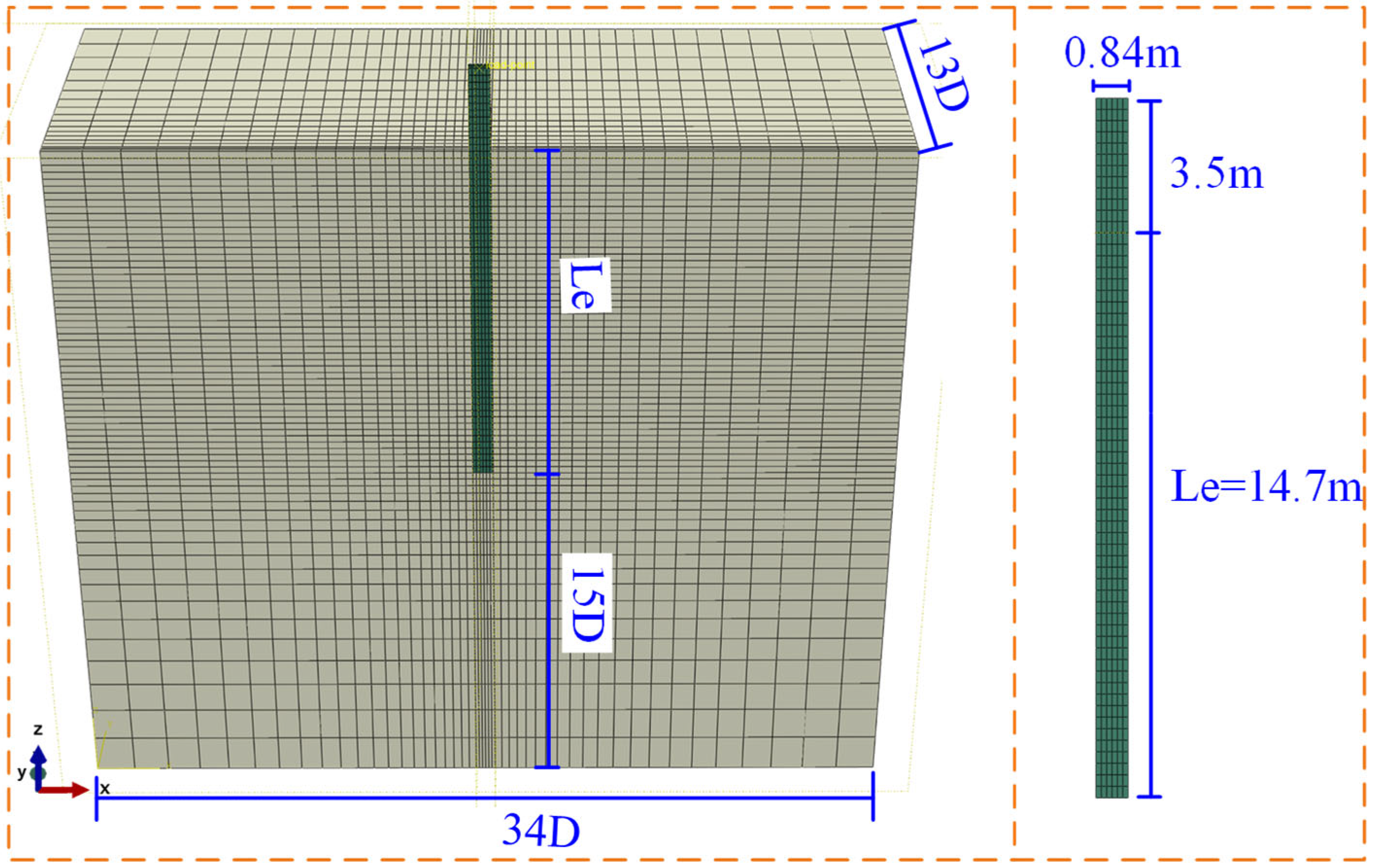
Considering the symmetry of the laterally loaded pile foundation model, a symmetric FE model was adopted. To eliminate boundary effects, the soil domain was set to 34D in the x-direction and 13D in the y-direction, and the distance from the pile tip to the bottom boundary was 15D [29]. Figure 1 shows the representative FE mesh model used in this study. The FE analysis consisted of four steps:
(i)
Initial geostatic stress step: To reproduce the in situ stress state of the soil, the lateral boundaries were constrained in the x-direction and the ground surface was restrained in the x-, y-, and z-directions. The two faces perpendicular to the vertical loading direction were assigned a y-direction displacement constraint and a symmetry boundary condition, respectively. The pore pressure boundary condition was applied at the top surface of the soil and the permeability coefficient of the soil was taken as 2 × 10⁻⁸ m/s. Owing to this low permeability, undrained conditions were assumed. Gravity and an initial stress field were applied to establish the in situ geostatic stress state, and the at-rest earth pressure coefficient was K 0 = 1 sin φ = 0.4 .
(ii)
The model pile was installed using the “wish-in-place” approach, and the pile–soil interface properties were specified accordingly. Tangential and normal contact behaviours were defined using the Coulomb friction formulation in ABAQUS. Following Wang et al. [29]’s method, the friction coefficient of 0.32 was assigned to the pile–soil interface [47]. Hard contact was adopted in the normal direction with separation allowed, and gravity was applied to the pile.
(iii)
The “model change” technique in the finite element software was used to deactivate the soil elements within the prescribed scour depth, thereby simulating the formation of a general scour hole and capturing the soil stress history and the associated evolution of its physical and mechanical properties during scour. During the model-validation stage, this step was not implemented to ensure consistency with the centrifuge tests; a comparison was used to assess the validity and accuracy of the FE model.
(iv)
The displacement-controlled lateral load was applied to the model pile at the loading point in the direction of the symmetry plane in the model. The pile surface was kinematically coupled to a single reference (loading) point, and the lateral displacement was imposed at this point to facilitate the extraction of the numerical results.
Eight-node trilinear displacement–pore pressure elements (C3D8P) were employed to model the soil, whereas the piles were simulated using eight-node linear brick elements with reduced integration (C3D8R). In the finite element model, the mesh of the soil surrounding the pile was refined; the size gradually increased with increasing distance from the pile. The built-in surface-to-surface contact formulation with Coulomb friction in ABAQUS was used to model the pile–soil interaction, with separation between the pile and soil allowed. Mesh convergence analysis was performed for the FE simulations, wherein doubling the mesh density led to a change of less than 3% in the computed load–displacement response. The FE model shown in Figure 1 comprises 69,868 elements.

5. Comparison of Finite Element Results and Centrifuge Tests

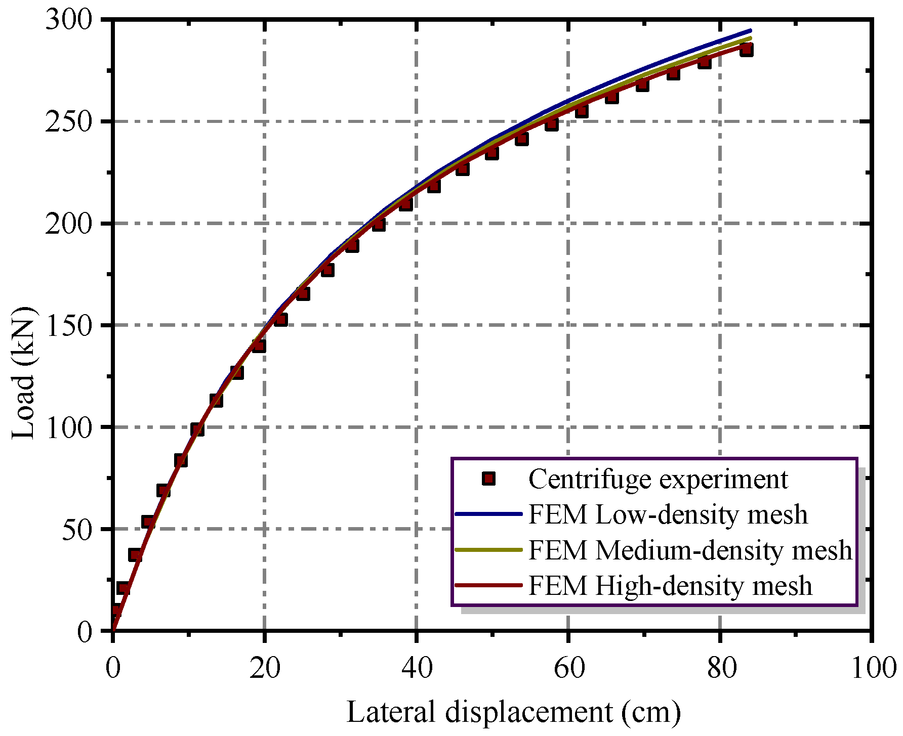
In Figure 2 we present a comparison between the pile-head load–displacement response predicted by the FE model and that measured in the centrifuge tests. Overall, the numerical predictions reproduce the experimental trend well over the full loading range, including the initial stiffness and the subsequent nonlinear softening as displacement increases. The close agreement indicates that the adopted constitutive description and pile–soil interface modelling are capable of capturing the key mechanisms governing the lateral response of the pile in clay. According to the API guideline for laterally loaded piles, the ultimate condition can be defined as when the lateral displacement at the mudline reaches 0.1D [38]. The FE model yields a response consistent with this criterion and the corresponding centrifuge observations, thereby confirming the accuracy and reliability of the proposed modelling framework for subsequent parametric analyses.
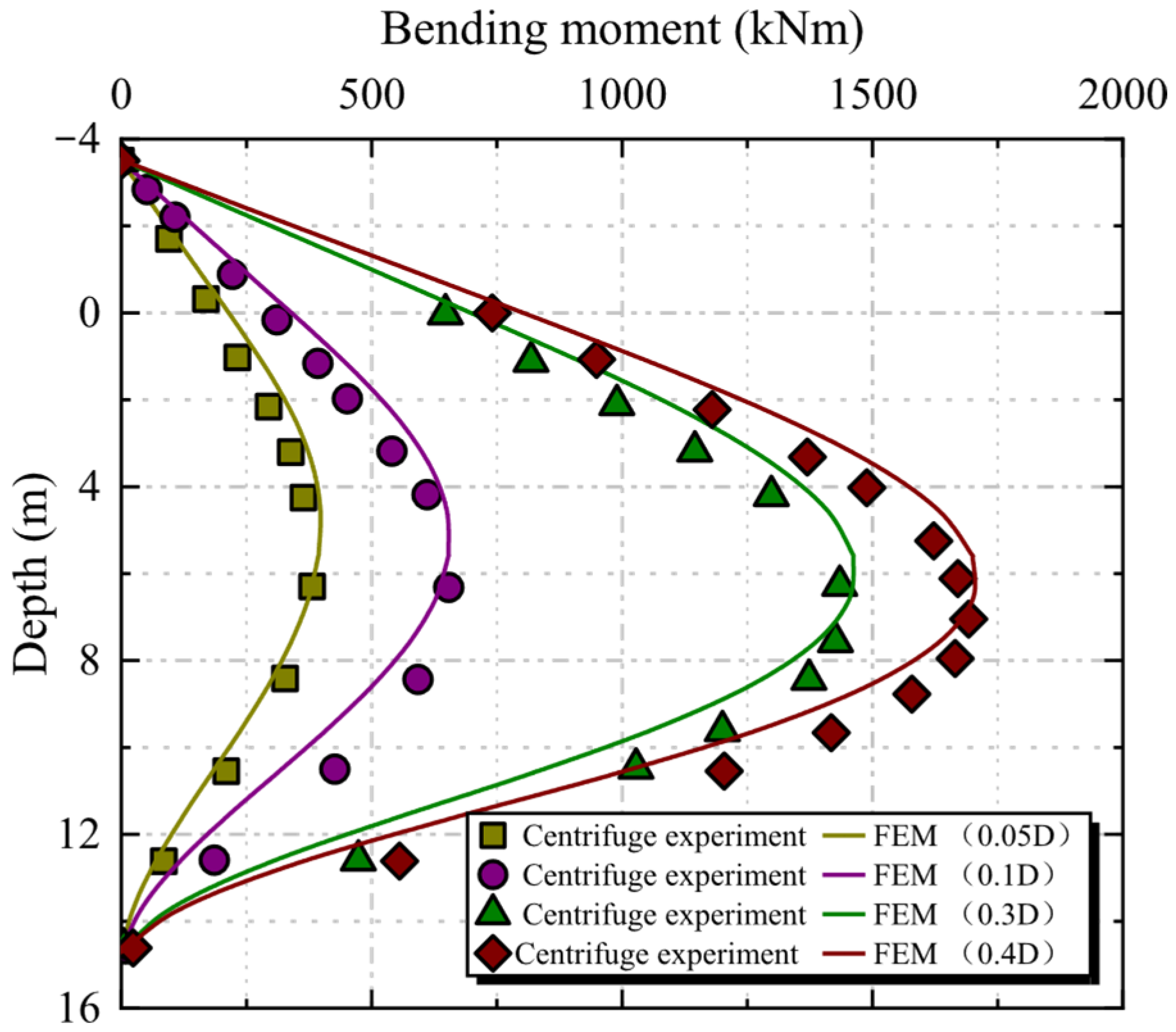
In Figure 3, we compare the bending moment–depth profiles obtained from the centrifuge tests and the FE simulations at four prescribed pile-head lateral displacements (0.05D, 0.1D, 0.3D, and 0.4D, where D is the pile displacement/diameter). Overall, the FE model reproduces the centrifuge measurements well across all displacement levels, capturing both the magnitude and shape of the moment distributions. As the pile-head displacement increases from 0.05D to 0.4D, the bending moment increases markedly and the moment profile becomes broader, indicating the progressive mobilisation of soil resistance over a larger depth range. The bending moment rises from the pile head to a distinct maximum located at an intermediate depth (approximately 6–8 m below the mudline) and then decays towards the pile toe, consistent with the development of a rotation point and deeper fixity. The peak moment increases systematically with displacement, reaching a value on the order of 1.8–1.9 MN·m at 0.4D. Minor deviations between the FE and centrifuge data occur locally (typically near the peak moment zone), but they remain close in agreement, confirming that the validated FE model can reliably predict the pile bending demand and its evolution with increasing lateral deformation.

6. Finite Element Result Analysis

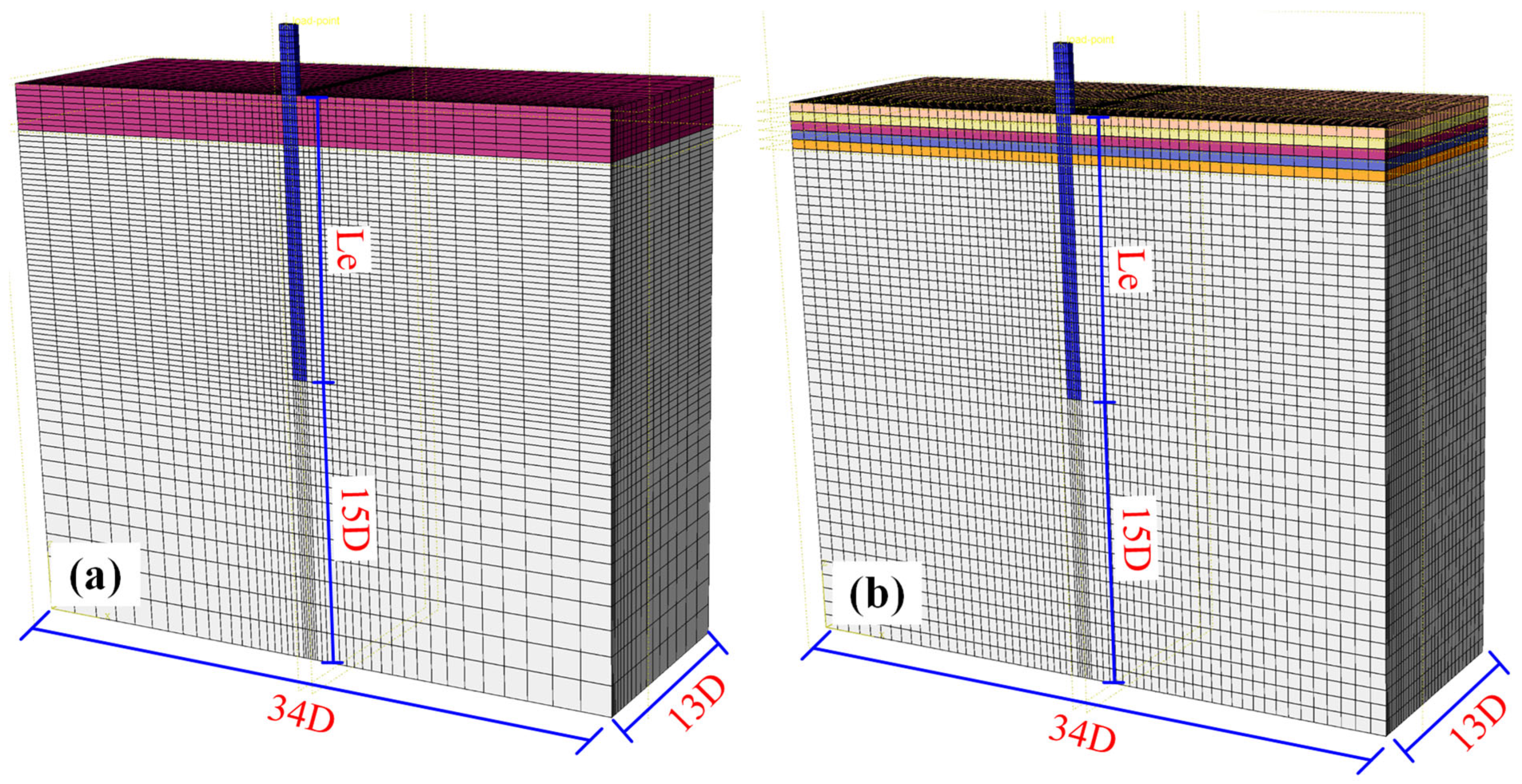
In this section, a parametric study was carried out to compare the lateral behaviour of square and circular piles with the same cross-sectional area to isolate the influence of pile shape from the effect of axial area. The pile–soil interaction under horizontal loading was examined under three representative conditions: (i) an unscoured baseline case, (ii) general scour to 2.5 m developed progressively by removing the soil in five increments of 0.5 m (corresponding to the coloured region in Figure 4b), and (iii) an instantaneous (one-step) scour in which the full 2.5 m of soil was removed at once (as indicated by the red region in Figure 4a). The progressive scour scheme was introduced to account for the evolution of the soil stress history during scour development, whereas the one-step scour represented the common idealisation adopted in conventional modelling. The FE models used in Figure 4 comprise 93,890 and 104,670 elements, respectively. In Figure 4a, soils of different colors in the upper part of the soil body represent the surface soil that was scoured away in one event. In Figure 4b, soils of different colors in the upper part of the soil body represent the surface soil that was sequentially scoured away.
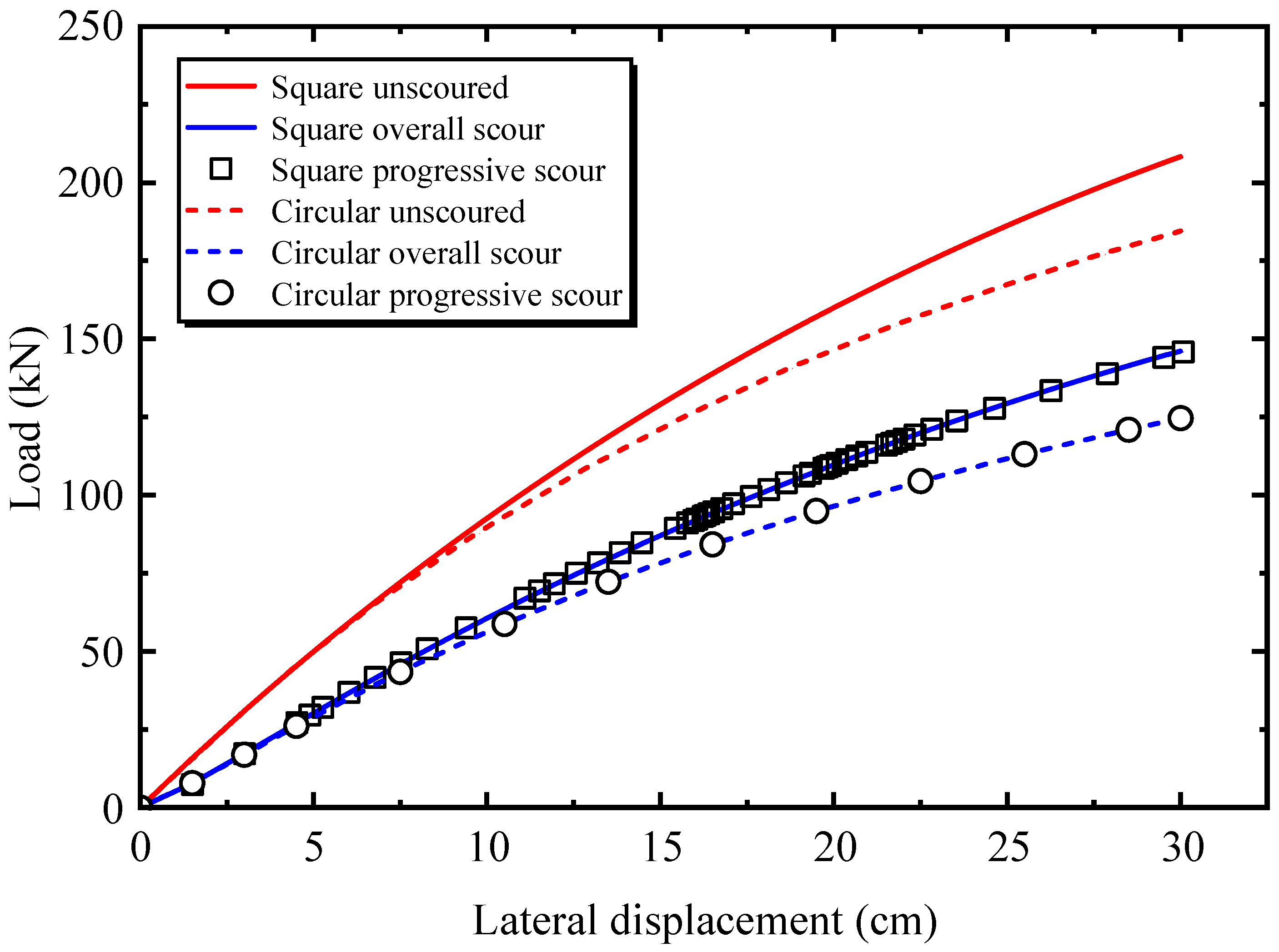
Figure 5 compares the load–displacement responses of square and circular piles with the same cross-sectional area under three conditions: unscoured, overall (one-step) scour, and progressive (staged) scour. For a given scour depth in clay, the curves obtained from the overall and staged scour simulations are almost coincident, indicating that, within the investigated range, the method used to impose scour (instantaneous versus incremental removal) has a minor influence on the lateral load–displacement relationship of the pile. At a pile-head lateral displacement of 30 cm, the lateral capacities of the square and equal-area circular pile under unscoured conditions are 208.32 kN and 184.57 kN, respectively. Under staged scour, the corresponding capacities decrease to 146.08 kN (square) and 124.67 kN (circular), highlighting the pronounced degradation in lateral resistance. Across both scour and unscoured cases, the square pile consistently mobilises a higher lateral resistance than the circular. Quantitatively, relative to the circular pile, the square provides an increase in lateral capacity of approximately 13% in the unscoured condition and 17.7% under scour. These results suggest that, for piles with an equal cross-sectional area, modifying the cross-sectional shape (from circular to square) can be an effective means of enhancing lateral load capacity, offering a practical design option to improve performance in scour-prone environments.
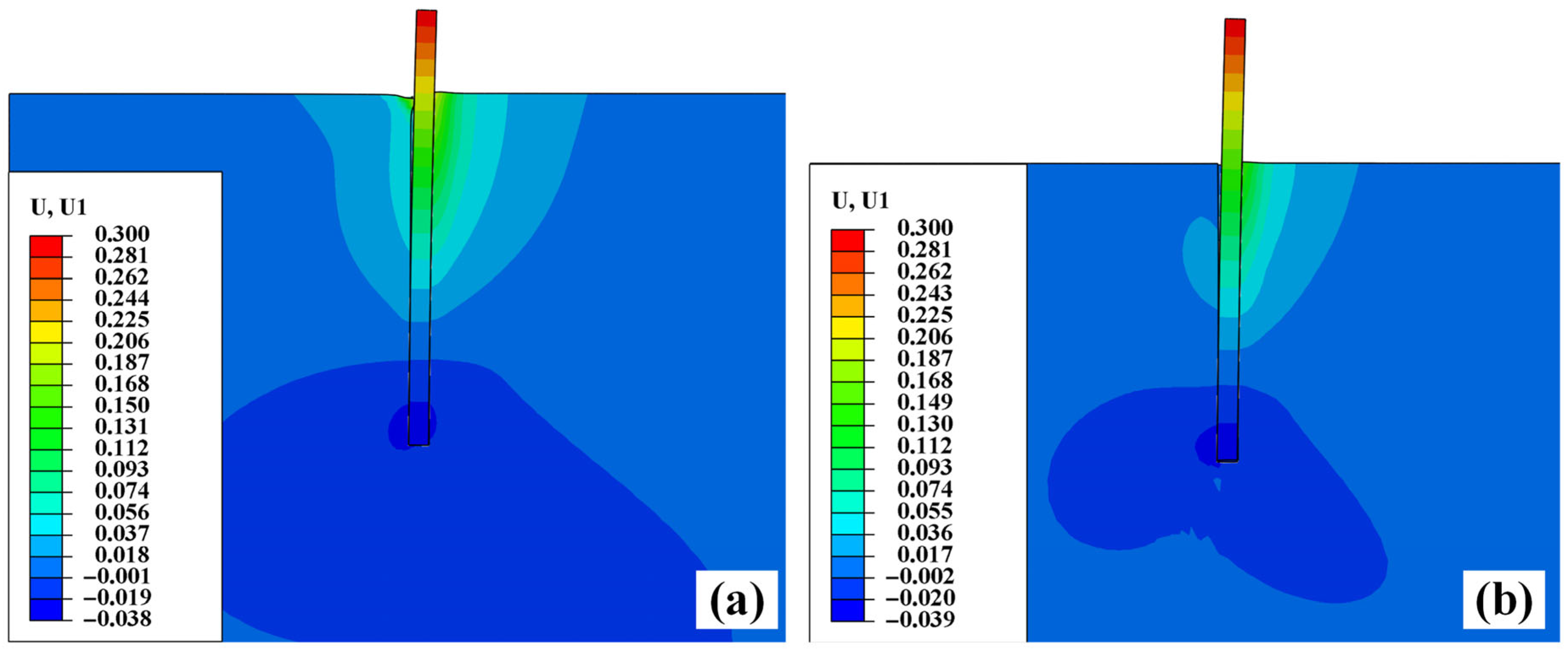
Figure 6 shows the horizontal displacement contours (U1) of the laterally loaded square pile–soil system under unscoured (Figure 6a) and scoured (Figure 6b) conditions. Compared with the former case, general scour leads to a progressive deepening of the wedge-type deformation/failure zone around the pile, indicating that the mobilised soil resistance is transferred to deeper layers as the near-surface confinement is removed. Meanwhile, the extent of the actively compressed (passive) soil zone in front of the pile becomes smaller after scour, reflecting the reduced availability of shallow soil to provide lateral support. Scour also increases the pile deformation above the post-scour mudline: the horizontal displacement of the pile segment exposed above the bed becomes more pronounced, and a clearer “kick-out” (toe deflection) develops near the pile tip, suggesting an enhanced pile rotation and a shift in the rotation point. These trends can be primarily attributed to the fact that general scour reduces the effective embedment depth and increases the load eccentricity of the lateral action, thereby weakening the lateral confinement provided by the shallow soil and amplifying pile deflection and rotation. For the same pile-head displacement, that is larger at the mudline after scour than that at the corresponding depth in the unscoured case, and the wedge-type deformation zone extends further downward. This phenomenon becomes increasingly evident with increasing scour depth, highlighting that the shallow clay strata contribute disproportionately to lateral resistance; once removed by scour, the lateral load-carrying capacity of the pile can be substantially reduced.
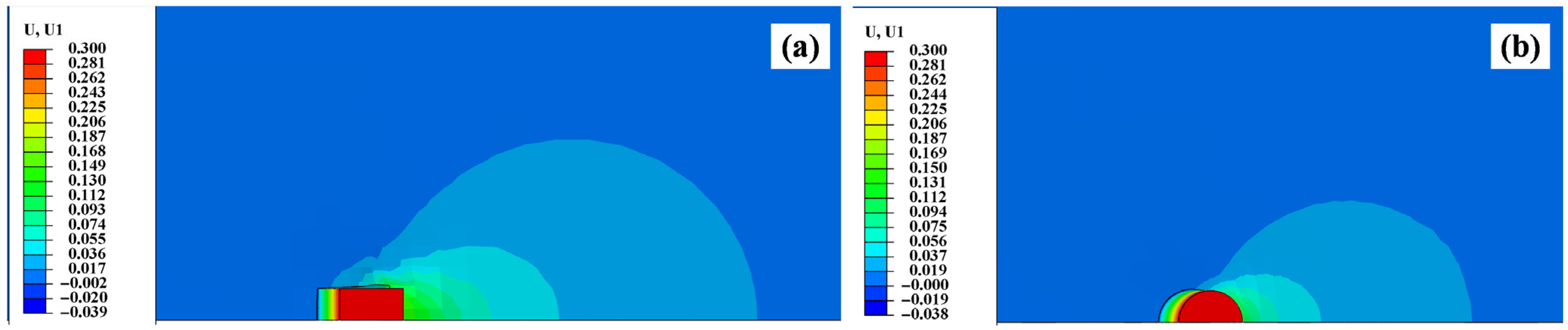
Figure 7 presents the horizontal displacement contours (U1) of the pile–soil system at the post-scour mudline under general scour, comparing the square (Figure 6a) and circular (Figure 6b) piles with equal cross-sectional areas. In both, a pronounced wedge-shaped deformation zone develops around the pile under lateral loading. As the distance from the pile increases, the displacement magnitude decays gradually and the affected region transitions from a highly deformed to a weakly deformed zone, allowing the surrounding soil to be conceptually divided into a plastic, elastic, and essentially undisturbed zone. Within the plastic zone, the displacement field around the square pile exhibits a more blocky/rectangular pattern over a limited area, consistent with the presence of flat pile faces that impose directional kinematic constraints on the adjacent soil. Moreover, along the loading direction, the square pile mobilises a noticeably larger wedge-shaped soil mass than the circular. In contrast, the soil behind the pile shows negligible horizontal displacement for both sections, indicating limited mobilisation in the wake region under the considered loading and boundary conditions. These observations suggest that, under both scoured and unscoured conditions, a laterally loaded square pile engages a larger volume of surrounding soil than an equal-area circular pile, thereby mobilising greater passive resistance. This larger mobilisation zone provides a mechanistic explanation for the consistently higher lateral capacity of the square pile observed in the load–displacement responses.
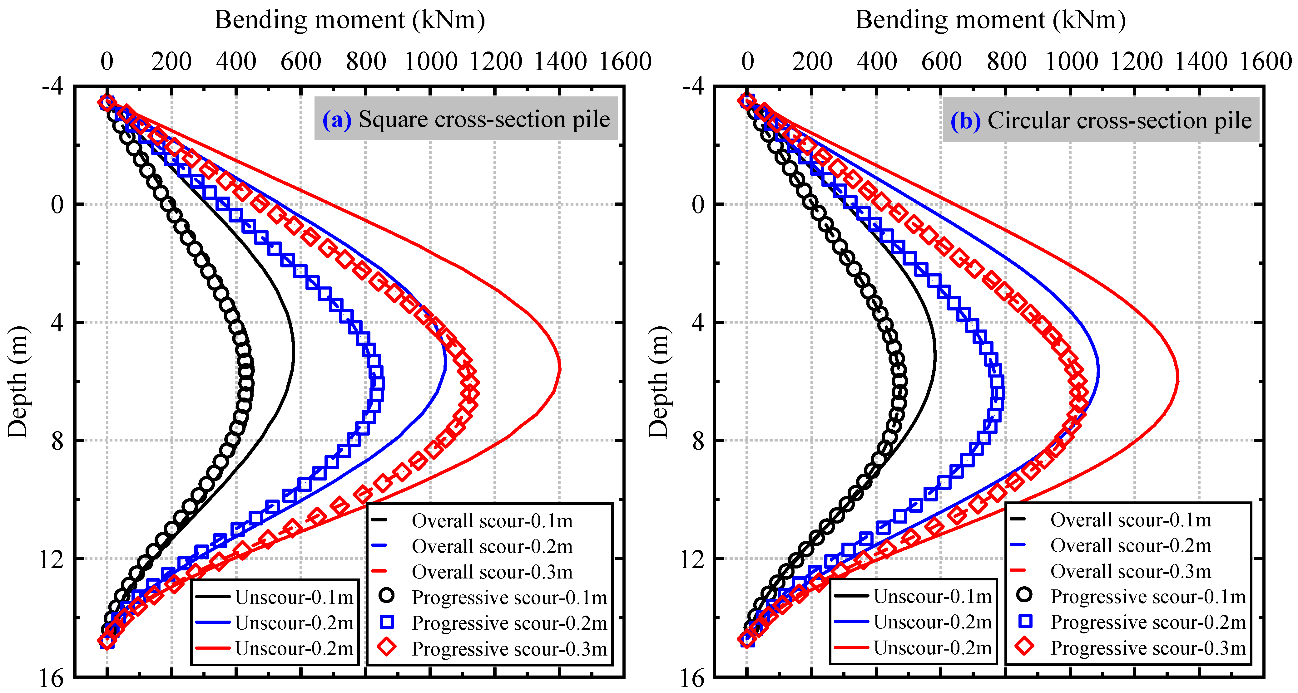
Figure 8 shows the bending moment–depth profiles of the pile under three prescribed pile-head lateral displacements (0.1 m, 0.2 m, and 0.3 m) for three conditions: unscoured, overall (one-step) scour, and progressive (staged) scour. For both the square- and circular-section piles, the unscoured case consistently exhibits larger bending moments than the scoured cases at the same depth, indicating that, under displacement-controlled loading, the pile mobilises a higher lateral reaction (and thus larger bending demand) when the near-surface soil confinement is intact. In contrast, scour reduces the available shallow resistance and leads to a smaller bending response throughout the upper portion of the pile. The overall and progressive scour results are nearly indistinguishable for all displacement levels, suggesting that explicitly modelling the staged scour process produces only marginal differences in the predicted bending moment distribution compared with the common one-step scour idealisation (for the depth considered). Notably, scour causes the location of the maximum bending moment to migrate downwards, reflecting a deeper mobilisation of soil resistance and a shift in the effective fixity/rotation region. When the scour depth reaches 2.5 m, the peak moment depth increases by approximately 0.4 m for the square and 0.7 m for the circular pile relative to the unscoured condition. At the largest imposed pile-head displacement (0.3 m), the peak bending moments for the square and circular piles are 1404.31 kN·m and 1335.33 kN·m in the unscoured case and decreasing to 1124.91 kN·m and 1021.06 kN·m under scour, respectively. Overall, the square pile develops a 5% (unscoured) and 10% (scoured) higher peak bending moment than the equal-area circular pile, implying that adopting a square cross-section can mobilise greater lateral resistance, and hence a higher lateral load-carrying capacity, particularly under scour conditions.
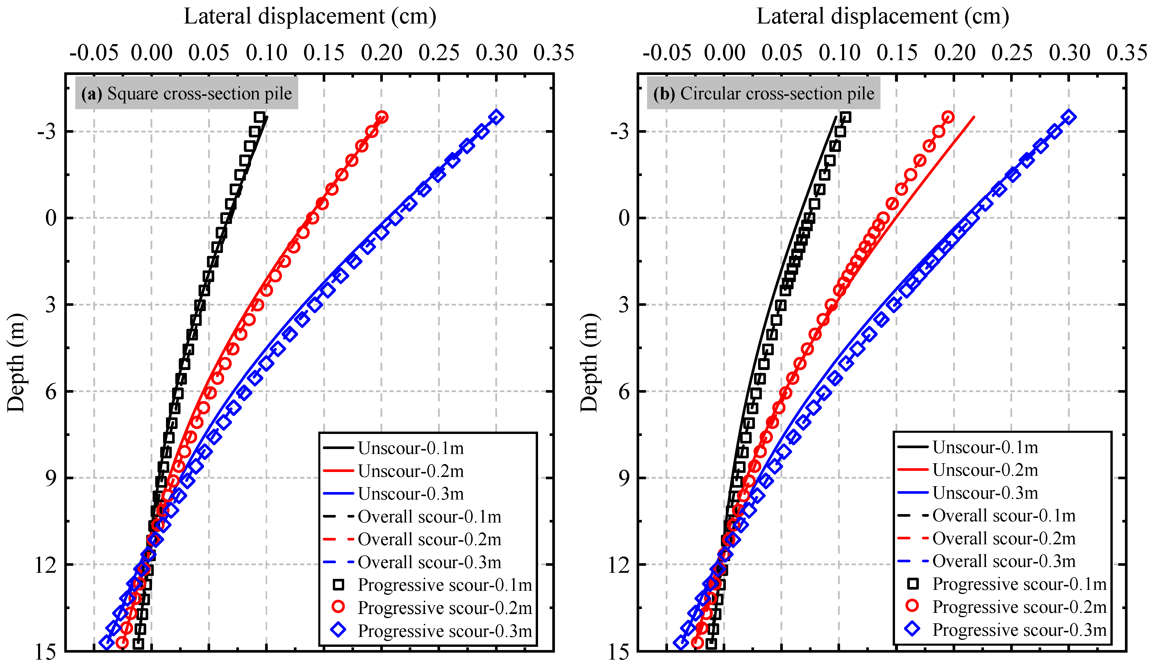
Figure 9 shows the lateral displacement–depth profiles for both the square- and circular-section piles under three prescribed pile-head displacements (0.1 m, 0.2 m, and 0.3 m) for three conditions: unscoured, overall (one-step) scour, and progressive (staged) scour. For a given pile-head displacement, the difference between the scoured and unscoured displacement profiles varies with depth: as it increases, the discrepancy first increases and then decreases, indicating that scour most strongly modifies pile deformation within an intermediate depth range rather than uniformly over the entire embedded length. This depth-dependent trend becomes more pronounced as the imposed pile-head displacement increases, reflecting progressively stronger nonlinearity and mobilisation of soil resistance with larger lateral deformation. Despite the clear influence of scour on the magnitude and shape of the displacement profiles, the depth of the zero-displacement point is only weakly affected by scour in the investigated cases, suggesting that, under displacement-controlled loading, scour primarily amplifies pile deformation above and near the mudline, while the position of the rotation point remains relatively stable. In addition, compared with the circular pile of an equal cross-sectional area, the square pile exhibits a shallower zero-displacement depth, implying a more pronounced near-surface rotation and a different distribution of bending and soil reaction along the pile. Overall, the results highlight that pile cross-sectional shape influences the deformation mechanism and the depth-wise mobilisation of soil resistance under scour conditions.
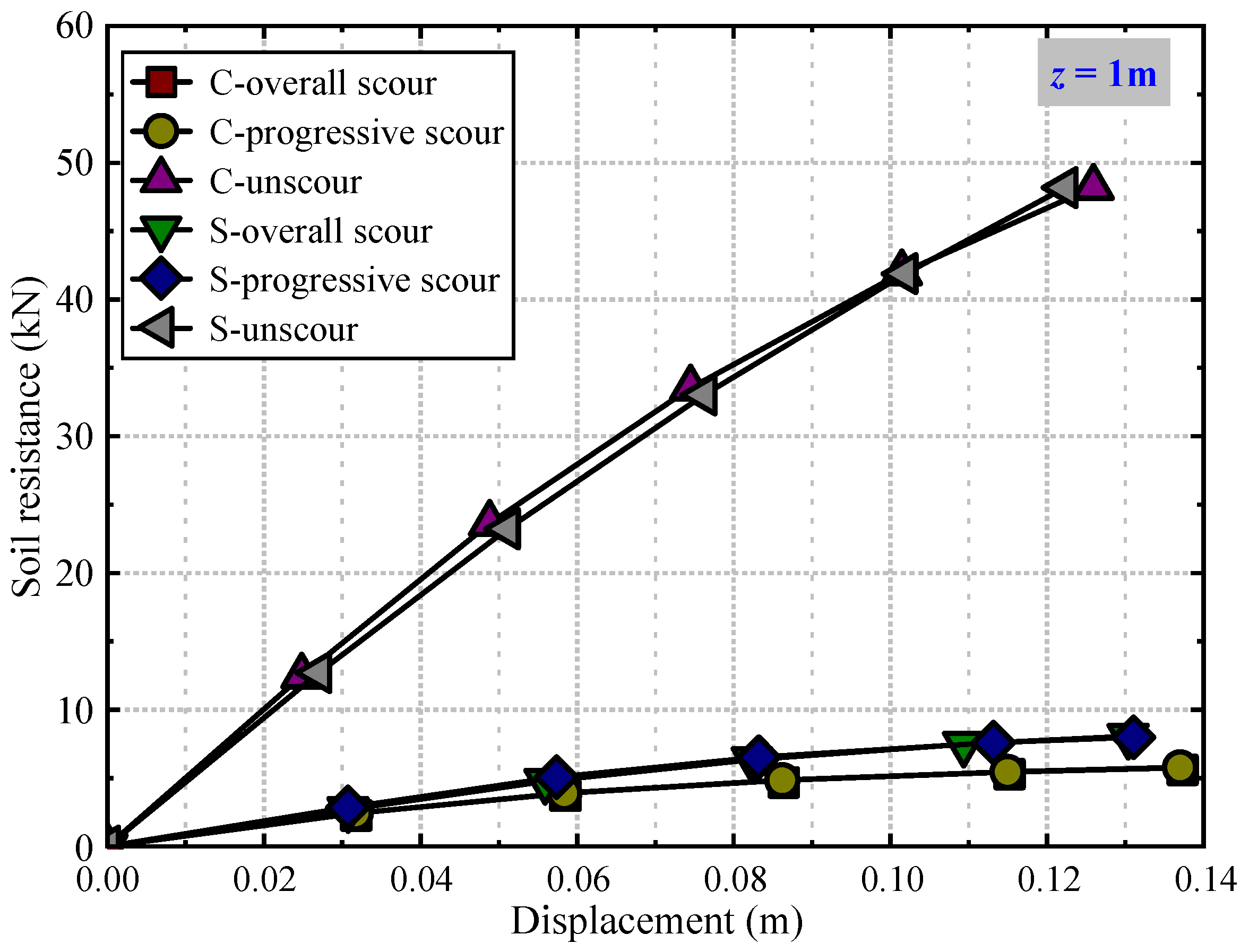
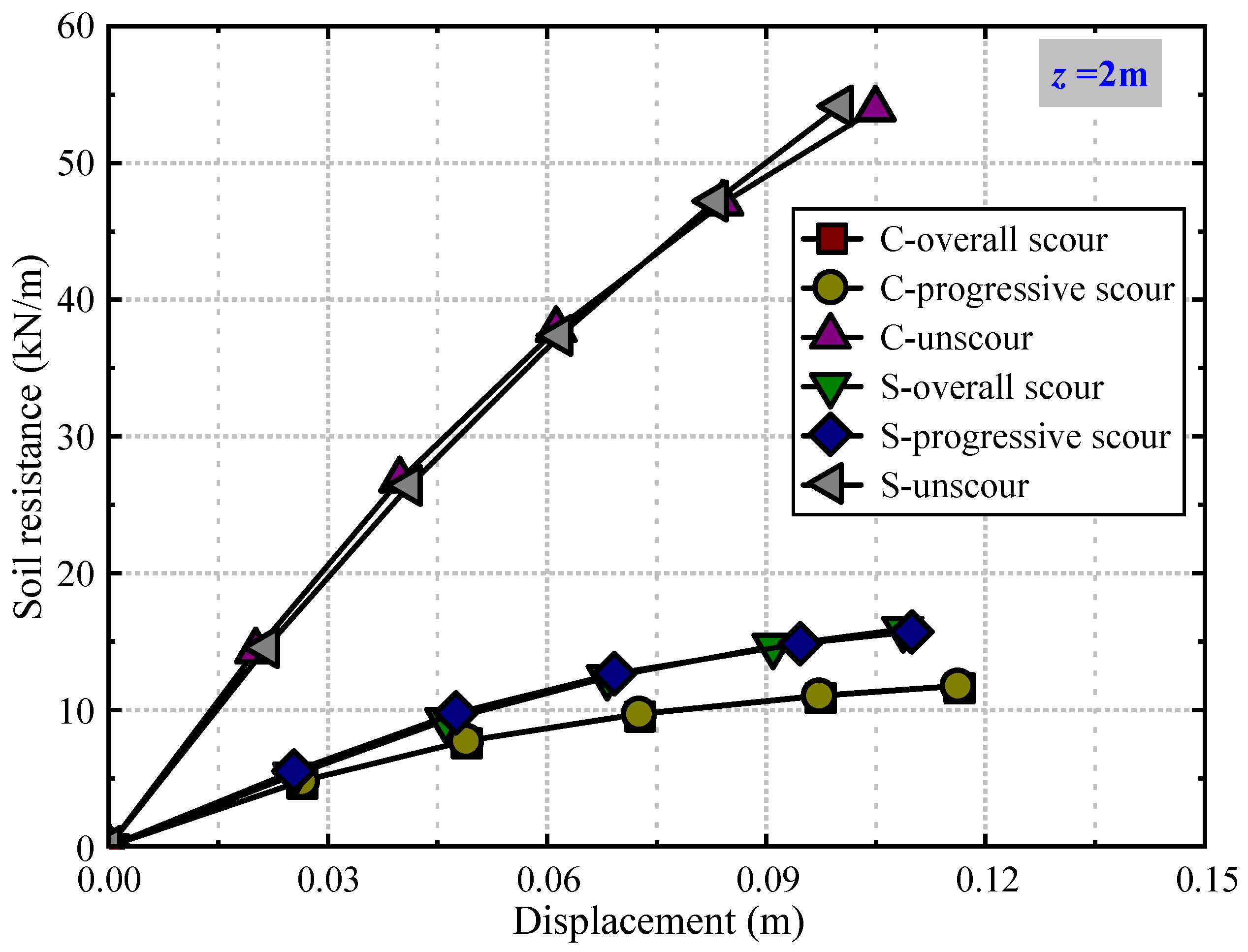
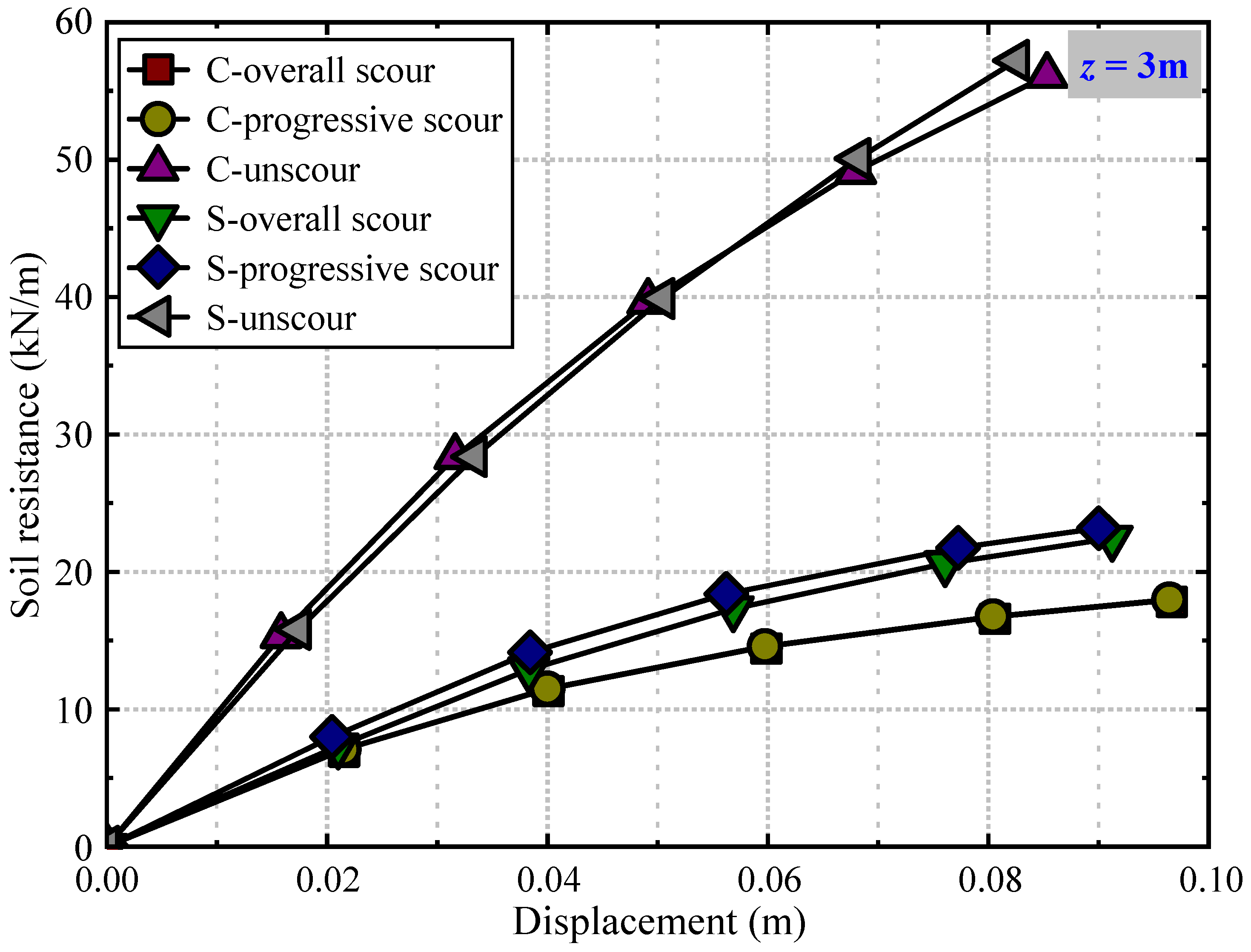
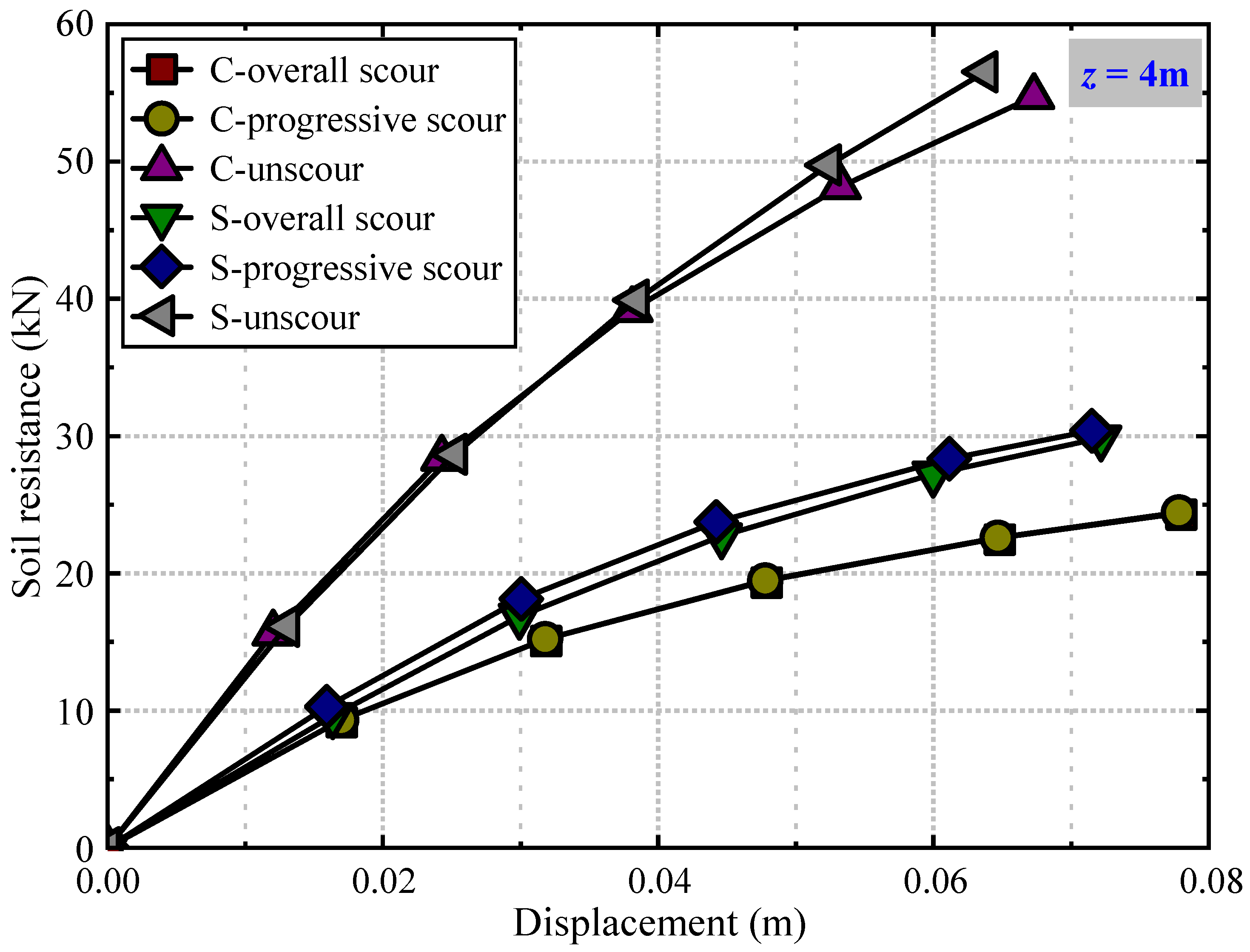
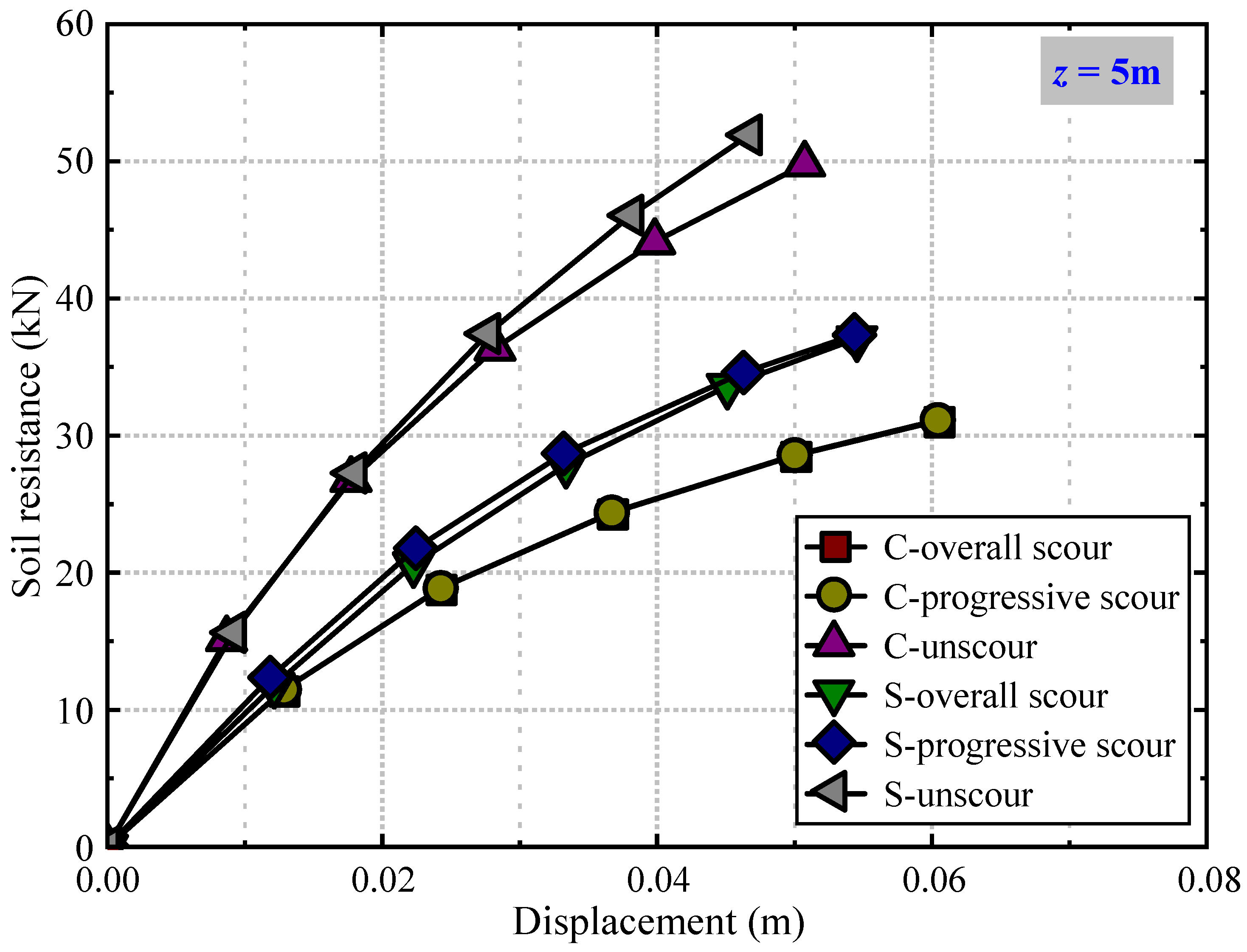
Figure 10, Figure 11, Figure 12, Figure 13 and Figure 14 compare the p-y curves at five depths below the post-scour mudline (1, 2, 3, 4, and 5 m) for equal-area circular (C) and square (S) piles under three conditions: unscoured, overall scour, and progressive scour. In the p-y curves, the soil reaction p was derived from the bending moment–depth profiles obtained from the FE analyses at each prescribed lateral displacement level. Each profile was first fitted using a fourth-order polynomial [29], and the corresponding soil reaction–depth relationship was then obtained by taking the second derivative of the fitted function. It should be noted that the depths shown in Figure 10, Figure 11, Figure 12, Figure 13 and Figure 14 are defined at the same pile length position measured from the pile tip; therefore, for the unscoured case, the overburden soil thickness equals the post-scour mudline depth plus the scour depth.
At a given depth, it can be observed that the soil reaction in the unscoured case is consistently higher than that in the two scour cases at the same imposed lateral displacement, reflecting the loss of near-surface confinement and the reduction in effective embedment caused by scour, which weakens the mobilised subgrade reaction in the upper soil layers. The influence of scour is most pronounced at shallow depths, whereas the discrepancy between the unscoured and scoured responses gradually diminishes with increasing depth below the post-scour mudline, indicating that the deeper soil retains a broadly similar stress state and continues to provide comparable resistance.
For a fixed pile cross-section, the overall scour case yields slightly lower soil resistance than the progressive case, although the differences remain modest across the displacement range considered. This suggests that, for the investigated clay and scour depth, the stress history effects associated with incremental scour development have a secondary influence on the resulting p-y response compared with the dominant geometric effect of removing overburden. In addition, under the same loading and scour condition, the square-section pile consistently mobilises a higher soil reaction than the equal-area circular pile, indicating a greater mobilisation of passive resistance in front of the pile and a larger engaged soil wedge, which translates into enhanced lateral stiffness and capacity. Overall, the comparisons confirm that modifying the pile cross-sectional shape from square to circular can improve the lateral load-carrying performance under unscoured, overall scour, and progressive scour conditions.

7. Conclusions

In this study, we established and verified a finite element model through centrifuge tests. Based on this verified model, we investigated the lateral bearing performance of square and circular pile foundations with equal cross-sections under general scour conditions (overall and distribution scour), addressing the pile responses and deformation failure modes of soils around the pile, yielding the following main conclusions:
(1)
General scour reduces the lateral bearing capacity for both circular and square cross-section pile foundations. Under no- and general scour conditions, square foundations exhibit increases in lateral bearing capacity of 13% and 17.7%, respectively, compared to circular. General scour decreases the effective embedment depth of pile foundations and increases load eccentricity, thereby reducing the wedge-shaped failure zone in soils around the pile, with the depth of this zone shifting deeper into the soil with scour.
(2)
In clayey environments, for a specific scour depth, overall and distribution scour exert minimal influences on the lateral bearing response of pile foundations, with nearly identical load–displacement relationships, bending moments, and displacement distributions along the depth.
(3)
When pile foundations bear the same displacement load, bending moment distributions along the depth first increase and then decrease. At the same depth, values under no-scour conditions exceed those under general scour conditions, with this difference becoming more significant as displacement load increases. The depth of the maximum bending moment shifts away from the initial mudline with general scour, and at the same depth, bending moment values for square cross-section piles surpass those for equal-area circular piles; therefore, adopting square cross-section pile foundations under scour conditions increases their lateral bearing capacity.
(4)
For both circular and square cross-section piles, general scour increases the lateral displacement of pile foundations but exerts minimal influence on the depth of the zero-displacement point, and the depth of this point for rectangular cross-section pile foundations is shallower than for circular.
(5)
At a given depth and lateral displacement, the unscoured case mobilises higher soil resistance than the scoured cases and the difference gradually decreases with depth. Overall and progressive scour produce similar p-y responses, and the equal-area square pile consistently develops greater soil resistance than the circular, indicating better lateral performance under all conditions. It should be noted that this study is limited to single piles in clay under idealised general scour conditions. Future research should therefore further consider more complex scour conditions and different soil types, and should develop modified p-y curves that explicitly account for the progressive formation of scour holes.

Author Contributions

Conceptualization, Z.W.; Methodology, Z.W. and T.L.; Formal analysis, T.L.; Investigation, L.P. and Y.L.; Data curation, X.D.; Writing—original draft, X.L.; Writing—review and editing, X.L.; Visualisation, B.D. and Y.X.; Supervision, B.M.; Project administration, B.M.; Funding acquisition, B.M. All authors have read and agreed to the published version of the manuscript.

Funding

The work was supported by the National Natural Science Foundation of China (grant no. 52508378 and 51778227); the Hunan Provincial Natural Science Foundation (2026JJ50476 and 2025JJ60340); the Open Research Fund of the Key Laboratory of Mountain Town Construction and New Technology, Ministry of Education (LNTCCMA-20250110); and the Scientific Research Fund of the Hunan Provincial Education Department (21A0308).

Data Availability Statement

The datasets presented in this article are not readily available because the data are part of an ongoing study. Requests to access the datasets should be directed to Binhui Ma.

Conflicts of Interest

Author Binhui Ma was employed by the company Hunan University of Science and Technology Engineering Testing Co., Ltd. The remaining authors declare that the research was conducted in the absence of any commercial or financial relationships that could be construed as a potential conflict of interest.

References

  1. Cao, G.; Ding, X.; Yin, Z.; Zhou, H.; Zhou, P. A new soil reaction model for large-diameter monopiles in clay. Comput. Geotech. 2021, 137, 104311. [Google Scholar] [CrossRef] [Scilit]
  2. Li, Q.; Askarinejad, A.; Gavin, K. Impact of scour on lateral resistance of wind turbine monopiles: An experimental study. Can. Geotech. J. 2021, 58, 1770–1782. [Google Scholar] [CrossRef] [Scilit]
  3. Peng, Y.; Liu, H.; Li, C.; Ding, X.; Deng, X.; Wang, C. The detailed particle breakage around the pile in coral sand. Acta Geotech. 2021, 16, 1971–1981. [Google Scholar] [CrossRef] [Scilit]
  4. Wang, C.; Liu, H.; Ding, X.; Wang, C.; Ou, Q. Study on the horizontal bearing characteristics of pile foundation in coral sand. Can. Geotech. J. 2021, 99, 1928–1942. [Google Scholar] [CrossRef] [Scilit]
  5. Zhu, B.; Ren, J.; Yuan, S.; Zhu, J.; Yang, Q.; Gao, Y.; Kong, D. Centrifuge modeling of monotonic and cyclic lateral behavior of monopiles in sand. J. Geotech. Geoenviron. Eng. 2021, 147, 04021058. [Google Scholar] [CrossRef] [Scilit]
  6. Lagasse, P.F. Countermeasures to Protect Bridge Piers from Scour; Transportation Research Board: Washington, DC, USA, 2007. [Google Scholar]
  7. Zhou, H.; Liu, H.L.; Wang, L.H.; Kong, G.Q. Finite element limit analysis of ultimate lateral pressure of XCC pile in undrained clay. Comput. Geotech. 2018, 95, 240–246. [Google Scholar] [CrossRef] [Scilit]
  8. Qi, C.-G.; Zheng, J.-H.; Zuo, D.-J.; Liu, G.-B. Experimental investigation on soil deformation caused by pile buckling in transparent media. Geotech. Test. J. 2018, 41, 1050–1062. [Google Scholar] [CrossRef] [Scilit]
  9. Yuan, B.; Sun, M.; Wang, Y.; Zhai, L.; Luo, Q.; Zhang, X. Full 3D displacement measuring system for 3D displacement field of soil around a laterally loaded pile in transparent soil. Int. J. Geomech. 2019, 19, 04019028. [Google Scholar] [CrossRef] [Scilit]
  10. Mohamed, Y.A.; Nasr-Allah, T.H.; Abdel-Aal, G.M.; Awad, A.S. Investigating the effect of curved shape of bridge abutment provided with collar on local scour, experimentally and numerically. Ain Shams Eng. J. 2015, 6, 403–411. [Google Scholar] [CrossRef] [Scilit]
  11. Nasr-Allah, T.H.; Moussa, Y.A.M.; Abdel-Aal, G.M.; Awad, A.S. Experimental and numerical simulation of scour at bridge abutment provided with different arrangements of collars. Alex. Eng. J. 2016, 55, 1455–1463. [Google Scholar] [CrossRef] [Scilit]
  12. Namaee, M.; Sui, J. Local scour around two side-by-side cylindrical bridge piers under ice-covered conditions. Int. J. Sediment Res. 2019, 34, 355–367. [Google Scholar] [CrossRef] [Scilit]
  13. Sheppard, D.M.; Melville, B.; Demir, H. Evaluation of Existing Equations for Local Scour at Bridge Piers. J. Hydraul. Eng. 2014, 140, 14–23. [Google Scholar] [CrossRef] [Scilit]
  14. Zubeldia, E.H.; Fourtakas, G.; Rogers, B.D.; Farias, M.M. Multi-phase SPH model for simulation of erosion and scouring by means of the shields and Drucker–Prager criteria. Adv. Water Resour. 2018, 117, 98–114. [Google Scholar] [CrossRef] [Scilit]
  15. Zou, X.J.; Cao, X.; Zhou, C.L.; Zhou, M.; Zhang, X.H. Experimental study on the bearing capacity of large-diameter monopile in sand under water flow condition. Ocean Eng. 2021, 224, 108708. [Google Scholar] [CrossRef] [Scilit]
  16. Yang, X.; Zhang, C.; Huang, M.; Yuan, J. Lateral loading of a pile using strain wedge model and its application under scouring. Mar. Georesour. Geotec. 2017, 36, 340–350. [Google Scholar] [CrossRef] [Scilit]
  17. Ma, L.; Wang, L.; Guo, Z.; Jiang, H.; Gao, Y. Time development of scour around pile groups in tidal currents. Ocean Eng. 2018, 163, 400–418. [Google Scholar] [CrossRef] [Scilit]
  18. Najafzadeh, M.; Kargar, A.R. Gene-Expression Programming, Evolutionary Polynomial Regression, and Model Tree to Evaluate Local Scour Depth at Culvert Outlets. J. Pipeline Syst. Eng. Pract. 2019, 10, 04019013. [Google Scholar] [CrossRef] [Scilit]
  19. Wang, Z.; Zhou, H.; Tong, L. (Eds.) Influence of Scour Depth on Pile Group with Complex Configuration in Clay. In Proceedings of the International Conference on Green Building, Civil Engineering and Smart City, Guilin, China, 8–10 April 2022; Springer: Singapore, 2022. [Google Scholar]
  20. Al-Mandeel, S.J. Behavior of Laterally Loaded Pile Group Model in Sand; King Fahd University of Petroleum and Minerals: Dhahran, Saudi Arabia, 2000. [Google Scholar]
  21. Amini, A.; Melville, B.W.; Ali, T.M.; Ghazali, A.H. Clear-Water Local Scour around Pile Groups in Shallow-Water Flow. J. Hydraul. Eng. 2012, 138, 177–185. [Google Scholar] [CrossRef] [Scilit]
  22. Brown, D.A.M.C.; Reese, L.C. Lateral load behavior of pile group in sand. J. Geotech. Eng. 1988, 114, 1261–1276. [Google Scholar] [CrossRef] [Scilit]
  23. Chen, Y.; Lu, F.; Namdar, A.; Cai, J. Working Mechanism of Pile Group with Different Pile Spacing in Dense Sand. Adv. Civ. Eng. 2019, 2019, 5376594. [Google Scholar] [CrossRef] [Scilit]
  24. Zhu, B.; Xiong, G.; Li, T.; Liu, J.C. Centrifuge model tests on laterally loaded piles in sand. Int. J. Phys. Model. Geotech. 2016, 16, 160–172. [Google Scholar] [CrossRef] [Scilit]
  25. Cheng, X.; Fang, Z.; Li, Q.; El Naggar, M.H.; Lu, D.; Du, X. Dynamic response of offshore wind turbine supported by suction bucket in clay considering scour. Ocean Eng. 2024, 313, 119414. [Google Scholar] [CrossRef] [Scilit]
  26. Li, Y.; Li, Y.; Guo, Z.; Xu, Q. Durability of MICP-reinforced calcareous sand in marine environments: Laboratory and field experimental study. Biogeotechnics 2023, 1, 100018. [Google Scholar] [CrossRef] [Scilit]
  27. Liang, F.-Y.; Wang, Y.-Q.; Han, J. Numerical Analysis of Scouring Effects on the Behavior of Pile Foundations with the Mohr-Coulomb Model. In Condition, Reliability, and Resilience Assessment of Tunnels and Bridges; American Society of Civil Engineers: Reston, VA, USA, 2011; pp. 82–87. [Google Scholar]
  28. Li, F.; Han, J.; Lin, C. Effect of Scour on the Behavior of Laterally Loaded Single Piles in Marine Clay. Mar. Georesour. Geotec. 2013, 31, 271–289. [Google Scholar] [CrossRef] [Scilit]
  29. Wang, Z.; Zhou, H.; Sheil, B. Effects of scour on the lateral response of piles in sand: Centrifuge tests and numerical investigation. Acta Geotech. 2025, 20, 2093–2112. [Google Scholar] [CrossRef] [Scilit]
  30. Wang, C.; Liang, F.; Yu, X. Experimental and numerical investigations on the performance of sacrificial piles in reducing local scour around pile groups. Nat. Hazards 2016, 85, 1417–1435. [Google Scholar] [CrossRef] [Scilit]
  31. Aamir, M.; Ahmad, Z. Review of literature on local scour under plane turbulent wall jets. Phys. Fluids 2016, 28, 105102. [Google Scholar] [CrossRef] [Scilit]
  32. Alemi, M.; Maia, R. Numerical Simulation of the Flow and Local Scour Process around Single and Complex Bridge Piers. Int. J. Civ. Eng. 2016, 16, 475–487. [Google Scholar] [CrossRef] [Scilit]
  33. Ciancimino, A.; Jones, L.; Sakellariadis, L.; Anastasopoulos, I.; Foti, S. Experimental assessment of the performance of a bridge pier subjected to flood-induced foundation scour. Geotechnique 2021, 72, 998–1015. [Google Scholar] [CrossRef] [Scilit]
  34. Biao, L.; Wen-Gang, Q.; Yifa, W.; Fu-Ping, G.; Shun-Yi, W. Scour-induced unloading effects on lateral response of large–diameter monopiles in dense sand. Comput. Geotech. 2024, 174, 106635. [Google Scholar] [CrossRef] [Scilit]
  35. He, B.; Lai, Y.; Wang, L.; Hong, Y.; Zhu, R. Scour Effects on the Lateral Behavior of a Large-Diameter Monopile in Soft Clay: Role of Stress History. J. Mar. Sci. Eng. 2019, 7, 170. [Google Scholar] [CrossRef] [Scilit]
  36. Kan, Y.; Wang, Q.; Lin, G. Measures to resist flood disaster of bridge gossing. J. Railw. Eng. Soc. 1998, 15, 40–46. [Google Scholar]
  37. Liang, F.; Zhang, H.; Huang, M. Influence of flood-induced scour on dynamic impedances of pile groups considering the stress history of undrained soft clay. Soil. Dyn. Earthq. Eng. 2017, 96, 76–88. [Google Scholar] [CrossRef] [Scilit]
  38. 2GEO AJAR. Geotechnical and Foundation Design Considerations; API: Washington, DC, USA, 2011. [Google Scholar]
  39. Shafts, D. Construction Procedures and Design Methods; US Department of Transportation, Federal Highway Administration: Washington, DC, USA, 1999; Volumes I and II.
  40. Qi, W.G.; Gao, F.P.; Randolph, M.F.; Lehane, B.M. Scour effects onp–ycurves for shallowly embedded piles in sand. Geotechnique 2016, 66, 648–660. [Google Scholar] [CrossRef] [Scilit]
  41. Chortis, G.; Askarinejad, A.; Prendergast, L.J.; Li, Q.; Gavin, K. Influence of scour depth and type on p–y curves for monopiles in sand under monotonic lateral loading in a geotechnical centrifuge. Ocean Eng. 2020, 197, 106838. [Google Scholar] [CrossRef] [Scilit]
  42. Wang, Z.; Zhou, H.; Franza, A.; Liu, H. Numerical evaluation of scour effects on lateral behavior of pile groups in clay. Comput. Geotech. 2022, 150, 104913. [Google Scholar] [CrossRef] [Scilit]
  43. Wang, Z.; Zhou, H.; Sheil, B.; Liu, H.; Wang, C. Numerical investigation of the lateral response of pile groups in sand under local scour conditions. Comput. Geotech. 2023, 159, 105435. [Google Scholar] [CrossRef] [Scilit]
  44. Lin, C.; Han, J.; Bennett, C.; Parsons, R.L. Case history analysis of bridge failures due to scour. In Climatic Effects on Pavement and Geotechnical Infrastructure; ASCE: Reston, VA, USA, 2014; pp. 204–216. [Google Scholar]
  45. Lin, C.; Han, J.; Bennett, C.; Parsons, R.L. Analysis of laterally loaded piles in soft clay considering scour-hole dimensions. Ocean Eng. 2016, 111, 461–470. [Google Scholar] [CrossRef] [Scilit]
  46. Ilyas, T.; Leung, C.F.; Chow, Y.K.; Budi, S.S. Centrifuge Model Study of Laterally Loaded Pile Groups in Clay. J. Geotech. Geoenviron. Eng. 2004, 130, 274–283. [Google Scholar] [CrossRef] [Scilit]
  47. Wang, L.; Wang, H.; Zhu, B.; Hong, Y. Comparison of monotonic and cyclic lateral response between monopod and tripod bucket foundations in medium dense sand. J. Ocean Eng. 2018, 155, 88–105. [Google Scholar] [CrossRef] [Scilit]
Figure 1. Finite element model mesh for centrifuge comparison.
Buildings 16 01285 g001
Figure 2. Comparison of finite element results and centrifuge tests.
Buildings 16 01285 g002
Figure 3. Comparison of finite element results and centrifuge tests for bending moment–depth curves.
Buildings 16 01285 g003
Figure 4. Finite element mesh model under general scour; (a) overall scour; (b) progressive scour.
Buildings 16 01285 g004
Figure 5. Comparison of load–displacement relationships of circular and square cross-section pile foundations under different scour conditions with equal cross-sectional areas.
Buildings 16 01285 g005
Figure 6. Pile-soil displacement profiles of square cross-section piles (a) before scour; (b) after scour.
Buildings 16 01285 g006
Figure 7. Pile-soil displacement profile at mud surface of square cross-section pile under general scour conditions (a) Square cross-section pile; (b) Circular cross-section pile.
Buildings 16 01285 g007
Figure 8. Bending moment–depth distribution of piles under different displacement loads in three conditions: (a) square cross-section pile; (b) circular cross-section pile.
Buildings 16 01285 g008
Figure 9. Displacement-depth distribution of piles under different displacement loads in three conditions: (a) square cross-section pile; (b) circular cross-section pile.
Buildings 16 01285 g009
Figure 10. The p-y curve at 1 m below the post-scour mudline for the square- and circular-section piles under three scenarios: unscoured, overall scour, and progressive scour.
Buildings 16 01285 g010
Figure 11. The p-y curve at 2 m below the post-scour mudline for the square- and circular-section piles under three scenarios: unscoured, overall scour, and progressive scour.
Buildings 16 01285 g011
Figure 12. The p-y curve at 3 m below the post-scour mudline for the square- and circular-section piles under three scenarios: unscoured, overall scour, and progressive scour.
Buildings 16 01285 g012
Figure 13. The p-y curve at 4 m below the post-scour mudline for the square- and circular-section piles under three scenarios: unscoured, overall scour, and progressive scour.
Buildings 16 01285 g013
Figure 14. The p-y curve at 5 m below the post-scour mudline for the square- and circular-section piles under three scenarios: unscoured, overall scour, and progressive scour.
Buildings 16 01285 g014
Table 1. Physical property parameters of kaolin clay.
Parameters of Kaolin ClayParameter Value
Unit Weight (γ)16 kN/m2
Water Content66%
Liquid Limit79.8%
Plastic Limit35.1%
Compression Coefficient (Cc)0.55
Rebound Coefficient (Cs)0.14
Permeability Coefficient (k)2 × 10⁻⁸ m/s
Undrained Shear Strength at 15 m Depth (Prototype)20 kPa
Undrained Shear Strength at 0 m (Prototype)0 kPa
Disclaimer/Publisher’s Note: The statements, opinions and data contained in all publications are solely those of the individual author(s) and contributor(s) and not of MDPI and/or the editor(s). MDPI and/or the editor(s) disclaim responsibility for any injury to people or property resulting from any ideas, methods, instructions or products referred to in the content.