1. Introduction
Turkey is located in a high seismic hazard zone, where both the design of new structures and the retrofitting of the existing building stock require particular attention to earthquake safety. Commonly used structural systems such as reinforced concrete, steel, timber, and masonry have distinct advantages and limitations depending on ground conditions and material properties [
1]. Steel structures provide lightness, ductility, and ease of construction [
2], while reinforced concrete members offer higher deformation capacity and superior fire resistance [
3]. The 6 February 2022 Kahramanmaraş earthquakes generated ground motions exceeding the values defined in the Turkish Seismic Hazard Maps, underlining the necessity of innovative seismic resilience strategies [
4]. Despite numerous analytical and small-scale experimental studies, few shake-table investigations have directly compared the influence of joint flexibility and different mortar types in steel frames. This study aims to fill this gap through full-scale dynamic testing, incorporating both in-plane and out-of-plane excitations. In this context, where site-specific spectra are often economically unfeasible, the design of structural systems with enhanced deformation capacity becomes essential [
5]. Recent earthquakes in Turkey have revealed that infill walls act as structural fuse elements, absorbing seismic damage and preventing major failures in primary load-bearing members. The absence of infill walls on certain stories has been associated with significant structural damage [
6,
7]. Therefore, strengthening infill walls is crucial for improving seismic performance. However, rigid interaction between infill walls and surrounding frames may also lead to adverse seismic effects such as soft-story formation, torsional irregularity, and short-column behavior. These mechanisms have been widely reported to amplify damage concentration in multi-story structures and compromise overall ductility. Therefore, achieving an optimal balance between frame confinement and infill flexibility remains a key design challenge in contemporary seismic engineering. At the same time, the construction sector is responsible for nearly 40% of global energy consumption and a substantial share of CO
2 emissions, posing a major challenge for sustainable development [
8]. To address this, geopolymer concrete has emerged as a promising alternative to traditional cement-based materials, offering lower carbon emissions and energy use, while in some cases exhibiting superior compressive and tensile strength as well as higher durability [
9,
10,
11,
12]. Within the scope of this study, a strengthening frame was designed by combining the lightweight and ductile advantages of steel structures with the beneficial role of infill walls. Geopolymer mortars were adopted as an alternative to conventional mortars, aiming to enhance seismic performance while contributing to sustainable and environmentally friendly construction practices.
In steel structural systems, the choice of section type and connection detailing has a direct influence on seismic performance. Previous studies indicate that closed sections (e.g., box profiles) are often preferred due to their high torsional rigidity and stable behavior, while welded connections are adopted to provide reliable assessment of joint performance [
13,
14]. Following this approach, the present study employed similar design choices, with the specific profiles and connection details described in
Section 2. Numerous studies in the literature have focused on improving the seismic performance of steel frames through various strategies, including bracing systems, damping devices, base isolation, and the use of infill materials [
15,
16,
17,
18,
19]. These investigations emphasize the importance of limiting buckling lengths, enhancing energy dissipation, and integrating complementary materials to improve seismic resilience. Accordingly, in the present study, box-section profiles were adopted for the moment-resisting steel frame, as they provide high torsional rigidity and stable flexural behavior. Furthermore, welded connections were preferred to ensure greater joint rigidity and enable more reliable assessment of frame–infill interaction during experimental testing.
At the same time, another critical factor influencing the seismic performance of steel structural systems is the presence and behavior of infill walls. Although infill walls are generally considered as non-structural partition elements, numerous studies have demonstrated their significant influence on the dynamic properties of buildings [
20,
21]. Under seismic loading, the presence of infill walls alters the period, mass, and stiffness of the system, thereby affecting both local and global failure modes. Moreover, they enhance damping capacity, increase lateral stiffness, and reduce shear forces, bending moments, and displacements in the primary structural members [
7,
22]. For this reason, infill walls are often regarded as a “structural fuse” element that mitigates damage in beams and columns [
23]. Earthquake observations have shown that buildings lacking infill walls, particularly on basement and ground floors, suffer severe damage [
6]. In the literature, the structural contribution of infill walls has been represented through equivalent strut models and finite element approaches. The macro-model simplifies infill behavior using equivalent struts based on geometric and mechanical properties [
24], while the micro-model employs detailed finite element representation to capture physical, mechanical, and geometric characteristics more realistically [
20]. The literature contains numerous studies investigating the seismic contribution of infill walls to both reinforced concrete and steel structural systems. Previous research has demonstrated that infill walls are not merely partition elements, but significantly enhance structural stiffness, energy dissipation, and load-bearing capacity [
17,
25,
26,
27]. Experimental and numerical findings consistently show that infill walls modify structural periods, reduce interstory drifts, and act as “structural fuses” by sustaining the initial damage while protecting the main load-bearing members [
7,
28]. However, studies focusing specifically on steel frames with infill walls remain limited, and the effects of wall–frame interaction and joint detailing on seismic behavior are not yet fully understood [
29]. This highlights a critical research gap regarding the role of infill walls in enhancing the seismic performance of steel structural systems.
In addition to seismic safety, sustainability has become a fundamental requirement for modern construction materials. Accordingly, this study investigates the potential of geopolymer mortars, an environmentally friendly alternative to conventional cement-based mortars, in achieving both earthquake-resistant design and sustainability objectives. Rapid population growth, industrialization, and urbanization have significantly increased global CO
2 emissions and energy consumption [
8,
30,
31]. The construction sector accounts for nearly 35% of total energy use, with conventional materials such as cement mortars and bricks contributing substantially to these emissions. To address this challenge, geopolymer concrete has been developed as a sustainable alternative to cement-based binders [
32,
33]. Produced by activating industrial by-products such as fly ash, ground granulated blast furnace slag, metakaolin, and quartz powder with alkaline solutions, geopolymer concretes offer lower energy demand and reduced CO
2 emissions compared to traditional cement [
34,
35,
36]. These properties highlight their growing potential as environmentally friendly construction materials. Numerous studies have investigated the production, physical–chemical properties, and mechanical performance of geopolymer mortars. Findings consistently show that mortars produced from fly ash, ground granulated blast furnace slag, metakaolin, marble powder, and other industrial by-products activated with alkaline solutions exhibit lower energy demand and CO
2 emissions, while achieving high compressive and flexural strengths [
12,
37,
38,
39,
40]. Additional advantages such as radiation resistance, thermal insulation, durability, and suitability for composite systems have also been reported [
41,
42]. In structural applications, geopolymer mortars have been successfully employed in column–beam joints, infill walls, and masonry structures, where they improved ductility, deformation capacity, and load-bearing performance [
43,
44,
45,
46]. Previous studies on shake-table tests focused on evaluating the contribution of stiffness and dynamic interaction of masonry infill walls in reinforced concrete structures using conventional mortar material [
47,
48,
49]. At the same time, fibre mortar material was experimentally verified for use in masonry-dominant structures under shake-table tests [
50]. However, there is no direct literature on evaluating sustainable geopolymer mortar material along with rigid and flexible joint configurations of steel framed structures under shake-table tests. Therefore, this research work focuses on bridging this research gap by integrating sustainability and flexibility within a single framework.
Despite these advances, very few shake-table investigations have quantitatively examined how sustainable mortar alternatives interact with different joint configurations in steel frame–infill systems. This lack of experimental evidence limits understanding of the combined effects of mortar type and connection detailing on seismic response.
The seismic performance of steel frames with infill walls made from geopolymer and conventional mortars, considering rigid and flexible joints, was investigated experimentally. Four single-span specimens were tested under simulated earthquake motions in in-plane and out-of-plane directions. The investigation aims to reveal the effects of different mortars and joint types on acceleration response, displacement capacity, and frequency content. The research contributes to a sustainable solution for seismic resilience. The research contributes to seismic resilience with a sustainable solution by: (i) providing an experimental investigation on rigid and flexible joint configurations in steel frames with conventional and sustainable mortars using shake-table tests, (ii) evaluating quantitatively the influence of different acceleration, displacement, and frequency content under eleven simulated ground motions, and (iii) assessing comprehensively the interrelation between mortars and joint types. The research aims to contribute to seismic resilience with a sustainable solution by considering structural and sustainability requirements and developing seismic design strategies for steel frames.
2. Material and Method
In this study, an experimental program was conducted to investigate the seismic performance of steel frames with infill walls. The program began with the selection and characterization of the materials used in specimen fabrication. Subsequently, frame configurations with different connection types and mortar alternatives were designed and prepared. The tests were performed on a shake table using selected earthquake records, and the acceleration, displacement, and damage mechanisms were thoroughly monitored. The experimental procedure was planned to evaluate the behavior of the systems under increasing levels of seismic excitation. The collected data were analyzed to assess the contribution of both conventional and geopolymer mortars in enhancing the seismic performance of steel frames. In this context, the materials, specimen configurations, experimental setup, earthquake records, test procedure, and data processing methods are presented in detail in the following subsections.
2.1. Materials
The experimental specimens were designed as single-span steel frames, in which box-section steel profiles of 80 × 5 mm with S235 grade were used for both columns and beams [
51]. The beam-to-column connections were detailed as moment-resisting joints using full penetration butt welds with E480 grade electrodes [
1]. The steel frames were produced in two different configurations, where the infill walls were connected either with rigid joints or flexible gaps. In both configurations, the infill walls consisted of 8 cm thick perforated brick units, while conventional cement-based mortar and geopolymer mortar were employed separately as the bonding materials. The mixture proportions of the conventional and geopolymer mortars are presented in
Table 1, the mechanical properties of the steel profiles in
Table 2, and those of the brick units in
Table 3.
The frame members were fabricated using S235 structural steel, verified through tensile coupon tests conducted in accordance with EN ISO 6892-1 [
52]. The average yield strength, ultimate tensile strength, and elongation at failure were 253 MPa, 366 MPa, and 29%, respectively. Where coupon data were unavailable, nominal mechanical properties specified in EN 10025-2:2019 for S235 were adopted [
53]. Welding operations followed approved Welding Procedure Specifications (WPS) and Procedure Qualification Records (PQR) based on EN ISO 15614-1:2017 [
54]. All joints employed 6 mm fillet welds executed using E6013 electrodes, with visual inspection (VT) and penetrant testing (PT) carried out according to EN ISO 5817:2014 (Quality Level B) [
55]. No unacceptable discontinuities or surface defects were observed during inspection, confirming compliance with the acceptance criteria.
The solid clay brick units used in the infill panels had an average dry density of 1.85 g/cm
3, measured according to TS EN 12350-6 [
56]. The compressive strength tests were performed in compliance with TS EN 12350-1 [
57] using capped specimens to ensure uniform load distribution.
Geopolymer and conventional mortars were prepared according to the mixture proportions in
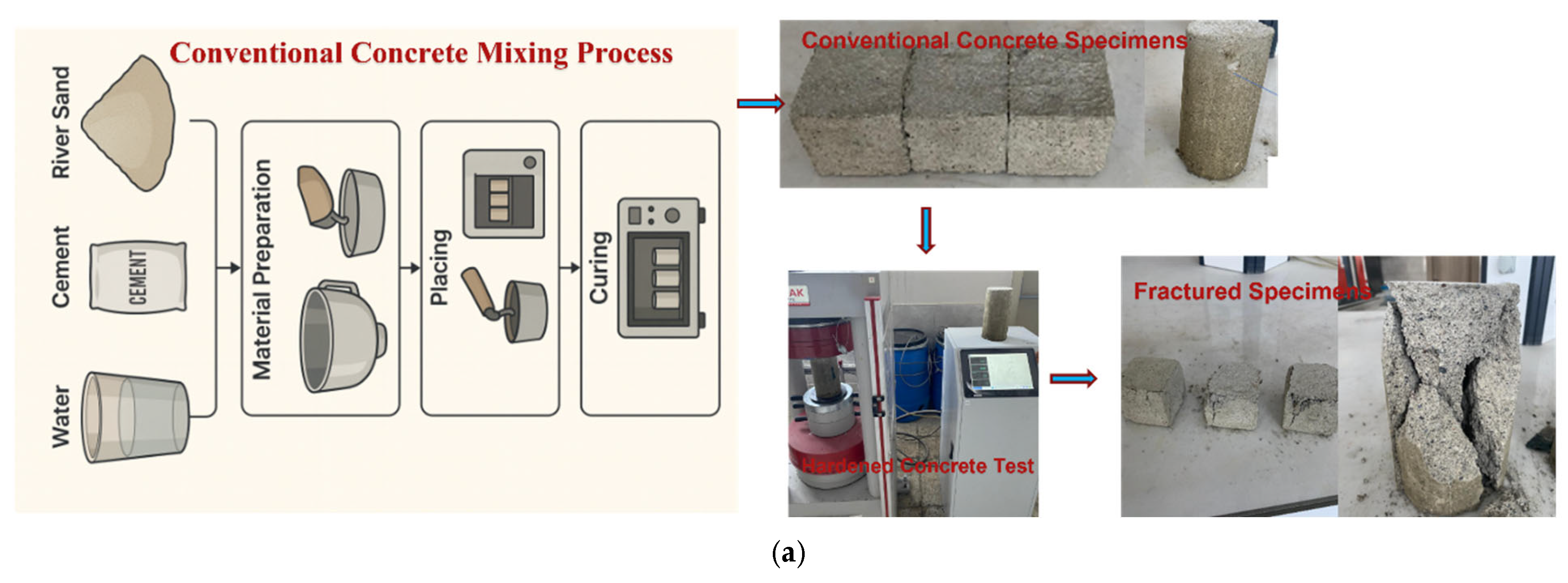
Table 1. As shown in
Figure 1a, conventional cement mortars were mixed, cast into 5 × 5 × 5 cm cubes and 10 × 20 cm cylinders, and tested for compressive strength after curing [
57].
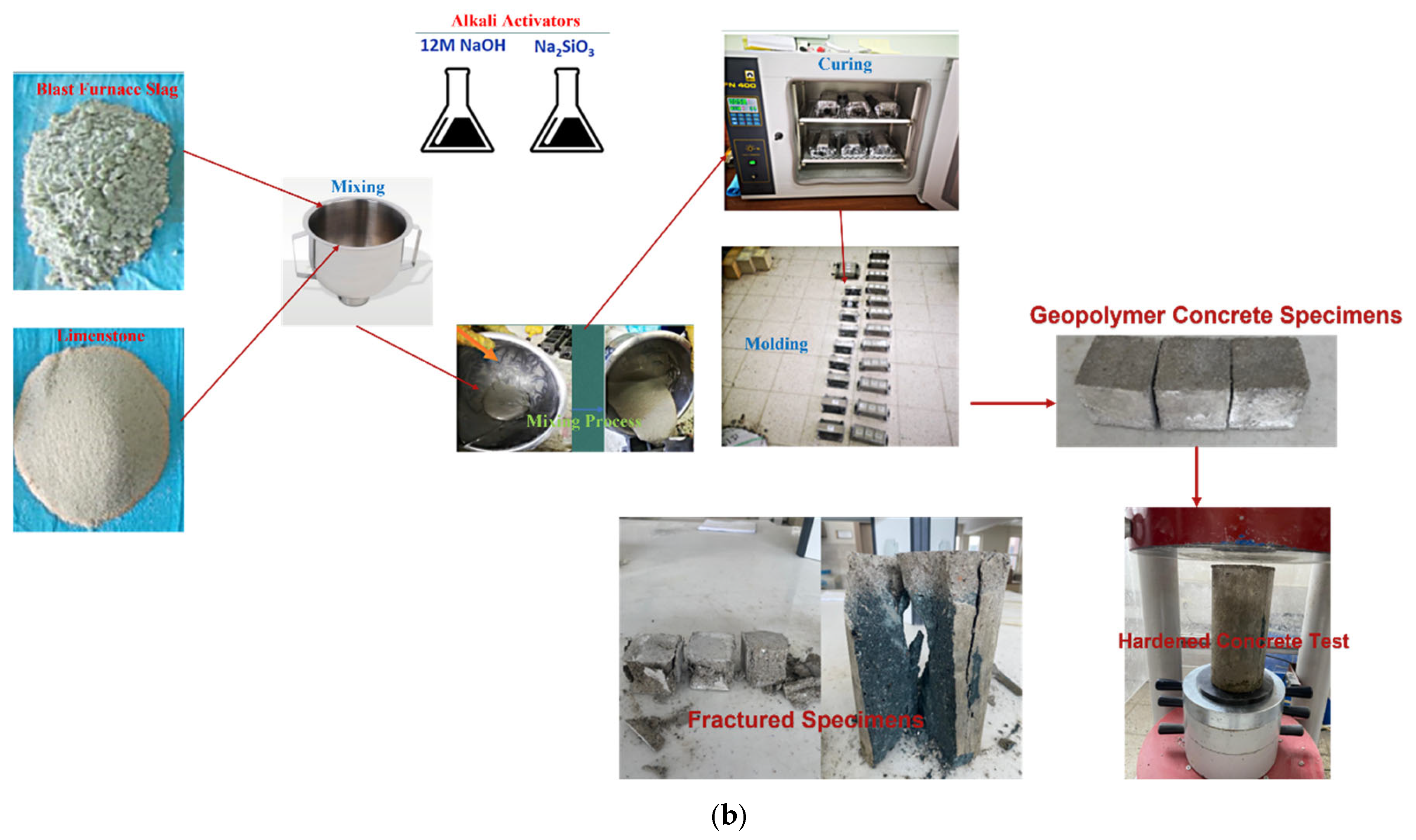
Figure 1b illustrates the geopolymer mortar production, in which blast furnace slag was activated with sodium hydroxide and sodium silicate, cast into identical molds, and cured at 60 °C for 24 h. Both mortar types achieved compressive strengths of 12–13 MPa, with geopolymers exhibiting denser microstructure and smoother fracture surfaces. The dry unit weight of all specimens was 2.23 g/cm
3 [
56]. The geopolymer mortars were produced using a Na
2SiO
3/NaOH ratio of 2.0, a sodium hydroxide concentration of 12 M, and an activator modulus (Mₛ) of 1.6. The fresh mixtures were cast immediately after blending and cured at 60 °C for 24 h to ensure proper geopolymerization [
9,
33].
2.2. Specimen Design and Configurations
In this study, Four single-span steel frame specimens—denoted as RBGBH, RBGH, EDGBH, and EDGH—were prepared to represent rigidly connected and flexible-jointed configurations using geopolymer and conventional mortars. The specimens were categorized into two main groups:
In each group, one specimen employed geopolymer mortar, while the other used conventional cement mortar as the bonding material. All models were constructed using 80 × 5 mm box-section (SHS80 × 5 mm) S235 grade steel members, forming frames of 1450 mm span and 1500 mm height.
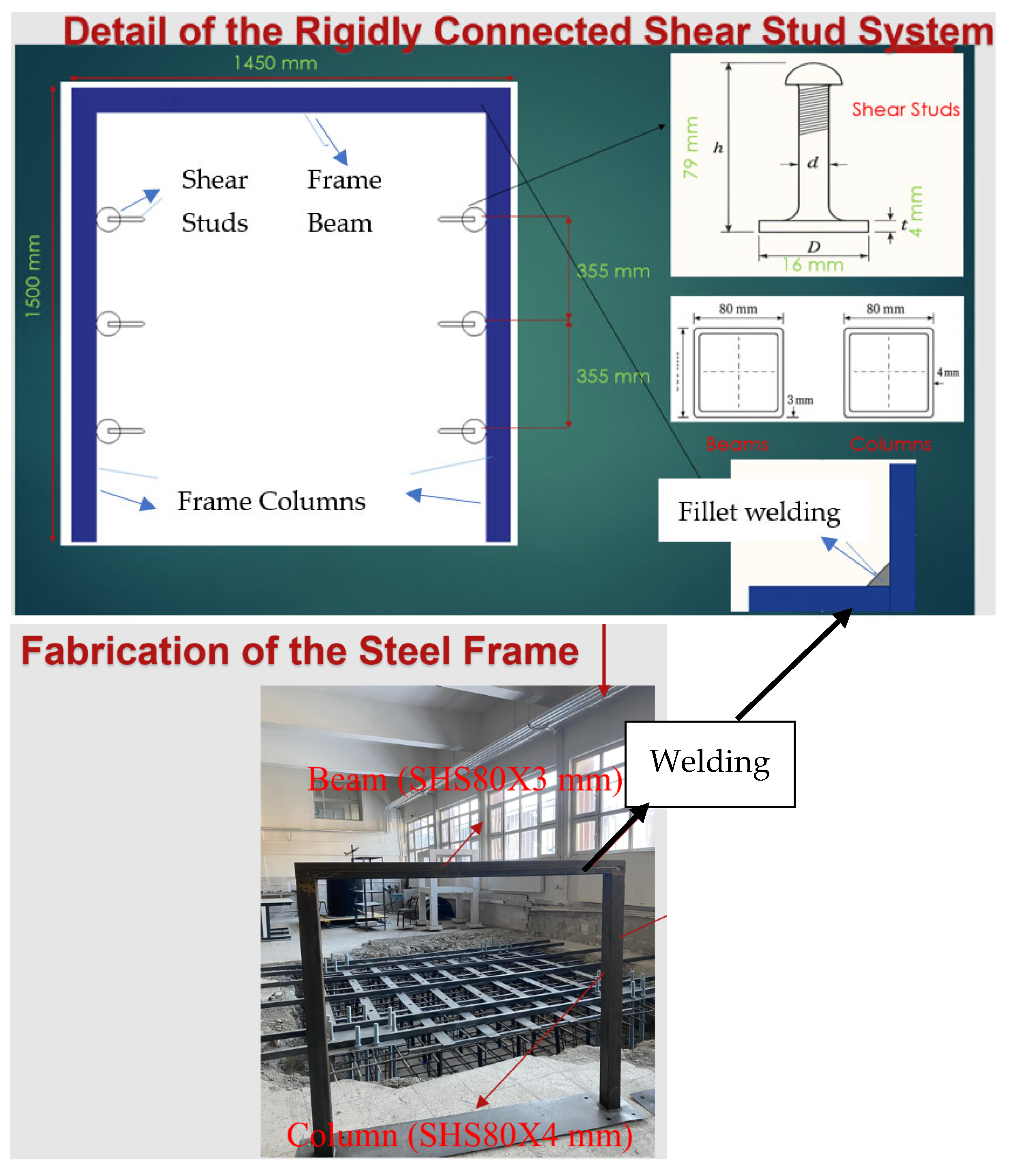
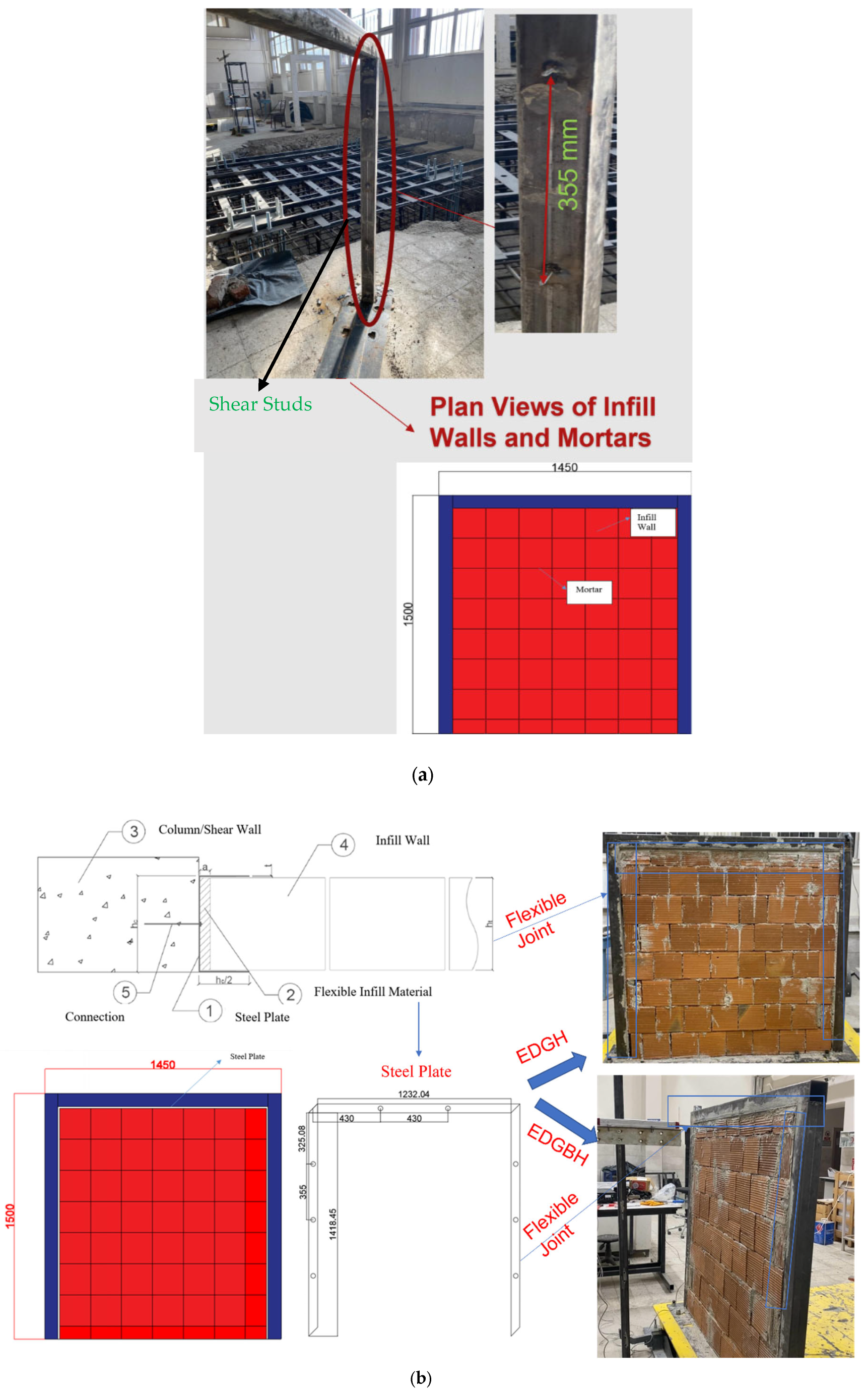
For the rigidly jointed systems, denoted as RBGBH (geopolymer mortar) and RBGH (conventional mortar), shear studs of 16 mm diameter and 79 mm height were welded to both column surfaces at 355 mm vertical spacing. These studs ensured the mechanical interlocking and enhanced shear transfer between the infill wall and the steel frame. The infill walls consisted of 8 cm thick perforated clay bricks, laid in a running bond pattern and fully bonded to the frame using the designated mortar. The rigid detailing effectively eliminated gaps between the wall and frame, promoting a monolithic behavior during seismic excitation. The fabrication sequence included the welding of frame elements, installation of studs, and construction of the infill panels. The finished models, illustrated in
Figure 2a, represent typical rigidly connected steel frame systems with geopolymer and conventional mortars. The second group, denoted as EDGBH (geopolymer mortar) and EDGH (conventional mortar), was produced with flexible joints designed to reduce direct wall–frame interaction. As shown in
Figure 2b, 2 mm thick steel plates were installed along the beam and column interfaces, creating a 20 mm-wide separation gap between the frame and the infill wall. This configuration was developed to simulate flexible boundary conditions, allowing limited contact during deformation and enhancing ductility under cyclic loading. The plates were anchored to the frame by bolts placed at intervals corresponding to the shear stud layout of the rigid specimens, ensuring comparable geometry and stiffness distribution. Both mortar types were applied under identical construction and curing conditions. In this case, the welded shear studs provide full mechanical interlocking between the structural steel frame and the masonry infill, thus fully preventing interface slip under seismic action. Therefore, the rigid structural system is considered fully composite with respect to the boundary condition, whereby the lateral loads are directly transferred from the infill to the adjacent structural frame members. On the other hand, the 20 mm intentional separation gap provides a partial decoupling mechanism between the structural steel frame and the infill wall. This detail results in reduced shear transfer between the structural frame and the infill wall, thus allowing for interface deformation.
The geometric dimensions, material properties, and construction stages of all specimens are summarized in
Figure 2, which provides comprehensive details of the frame configuration, connection detailing, and infill wall assembly for both rigid and flexible systems.
Each test specimen consisted of a single-span, single-story steel frame with a clear height of 1500 mm and a bay width of 1450 mm. The beam and column members were fabricated from square hollow steel sections, where the beams measured 80 × 80 × 3 mm and the columns 80 × 80 × 4 mm. The infill panels were constructed using solid clay bricks having nominal dimensions of 190 × 85 × 190 mm, laid in a stretcher bond arrangement. The mortar joint thickness was maintained at 10 ± 2 mm for both horizontal and vertical joints, using either conventional or geopolymer mortar according to the specimen type. The total infill thickness matched the brick width of 85 mm. Dimensional tolerances for the frame members were limited to ±2 mm, and those for the brickwork to ±3 mm, ensuring precise assembly. The as-built total masses of the specimens were measured as 56.2 kg for the rigid-jointed configurations and 54.7 kg for the flexible-jointed ones, which were later used in the interpretation of the dynamic test results and frequency-domain evaluations.
For clarity and consistency, the nomenclature adopted for all test specimens is presented in
Table 4, defining the relationship between joint type, mortar composition, and excitation direction shown in
Figure 2.
All infill walls constructed using masonry materials were constructed by a single skilled crew of masons under controlled laboratory conditions. The dimensions of blocks, building sequences, mortar application techniques, and durations of curing were consistent in all infill walls, which ensured consistency in experimentation. The small visual differences in infill walls, as depicted in photographs, can be attributed to finishing techniques.
2.3. Experimental Setup
The experimental program was conducted using an electromagnetic shaking table with a platform size of 2000 × 2000 mm and a payload capacity of 1.5 tons, capable of generating horizontal accelerations up to ±2 g and displacements of ±200 mm within the frequency range of 0.1–50 Hz. The input ground motions were selected and scaled in accordance with the Turkish Building Earthquake Code [
1]. A 16-channel data acquisition system (NI CompactDAQ) was employed to record synchronized acceleration and displacement data during all tests.
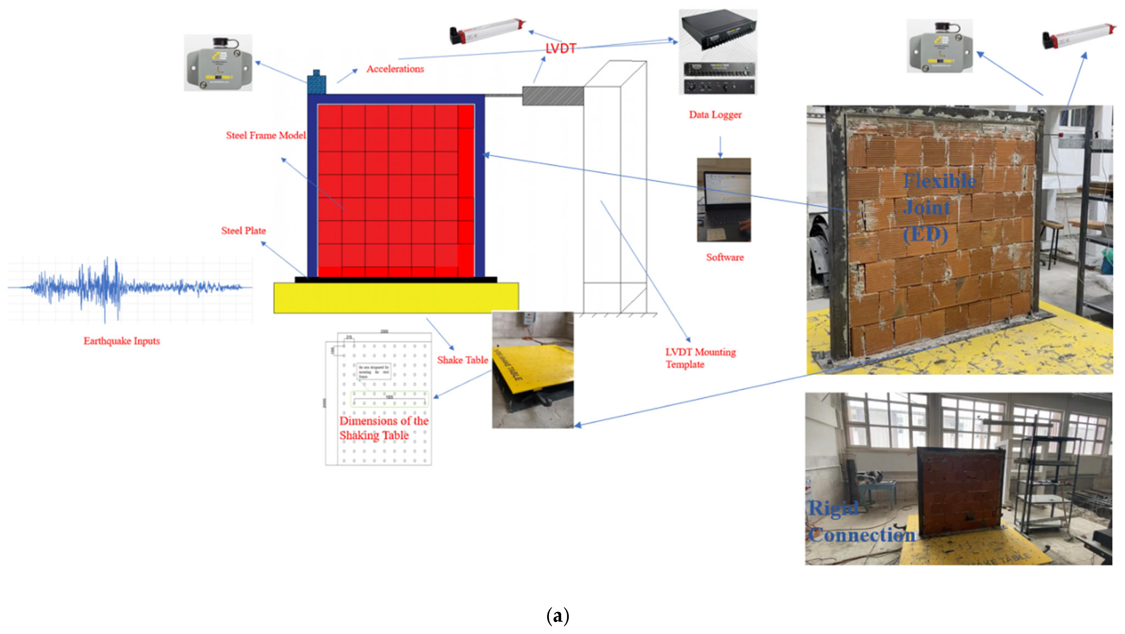
Figure 3a presents the in-plane shaking table configuration used to evaluate the lateral behavior of infilled steel frame systems. Both rigidly connected (RBGBH and RBGH) and flexible-jointed (EDGBH and EDGH) specimens were tested, employing geopolymer and conventional cement mortars, resulting in a total of four in-plane tests. High-precision uniaxial accelerometers (model SENSBOX 7008-T, Flytec USA, Inc., Doral, FL, USA, ±8 g range, ±0.5% FS accuracy, 1000 Hz sampling frequency) were mounted on the top beam of each frame to record horizontal accelerations. LVDTs (±200 mm range, 0.1% FS accuracy) were installed at beam–column interfaces to measure relative displacements. The collected data were transmitted to a 16-bit data logger and processed using custom MATLAB R2023b-based software for filtering and time–history analysis. Each specimen was rigidly anchored to the shaking table via a steel mounting template to ensure alignment and prevent base sliding. The input motion was applied in the longitudinal direction of the frames, and excitation amplitudes were increased incrementally until visible cracking and local separations occurred.
Figure 3a illustrates the instrumentation layout, data acquisition components, and actual specimen setup, including both connection types and mortar variations.
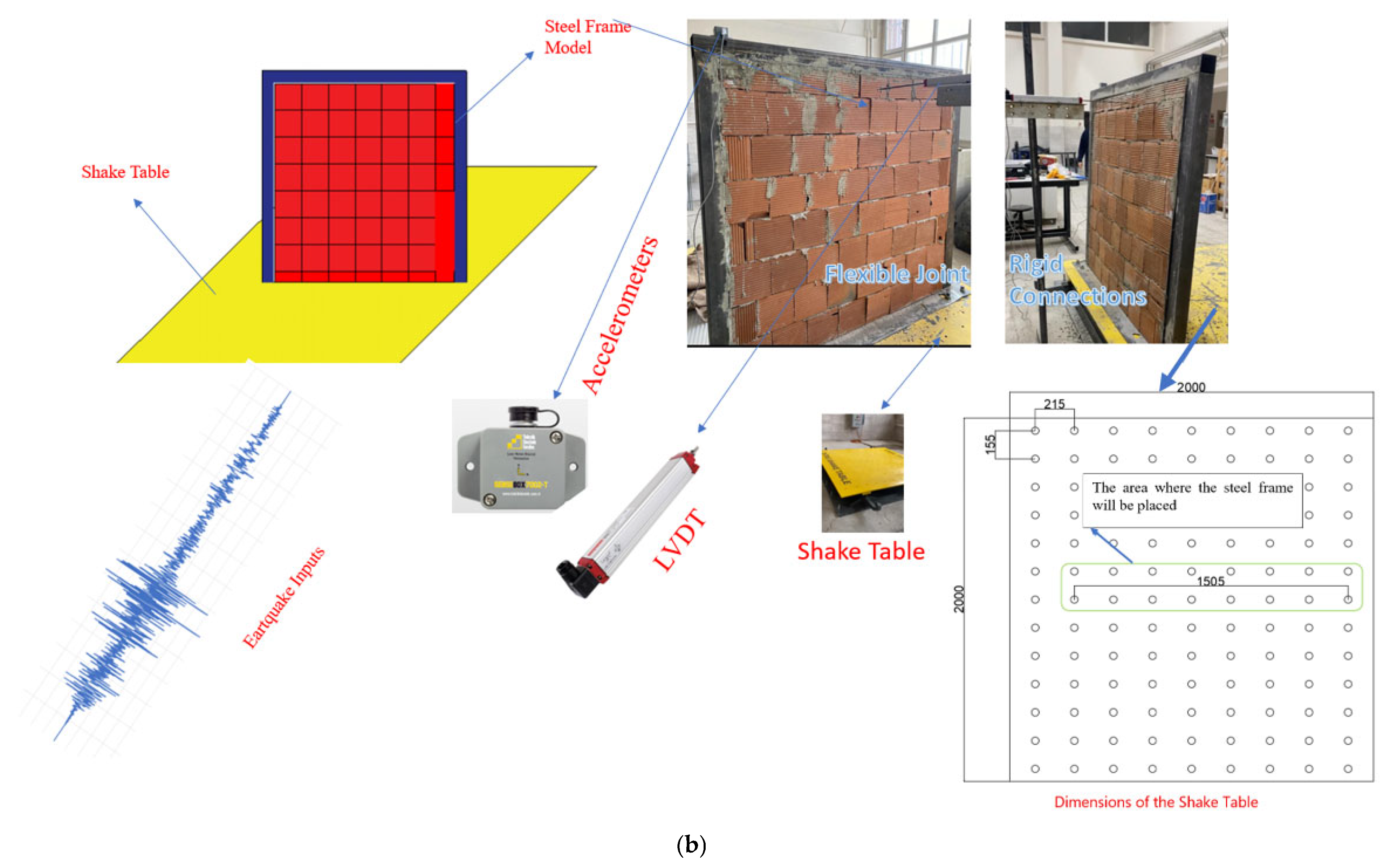
Dynamic response measurements were obtained using a network of triaxial accelerometers and linear variable displacement transducers (LVDTs) mounted at critical locations on the frame and shaking table, as illustrated in
Figure 3a,b. The data acquisition system operated at a sampling frequency of 1000 Hz for all channels. An anti-aliasing Butterworth filter with a cutoff frequency of 100 Hz was applied during acquisition to eliminate high-frequency noise. All sensors were factory-calibrated with an uncertainty of ±0.3%, and calibration certificates traceable to ISO 17025 [
58] were verified before testing. Mounting coordinates of the sensors were measured relative to the frame’s geometric center, and a right-hand sign convention was adopted, with positive directions defined along the excitation axis. All measurement channels were synchronized through a common hardware trigger to ensure phase consistency across acceleration and displacement data. The collected signals were subsequently processed for baseline correction, filtering, and spectral analysis prior to interpretation.
The out-of-plane tests were designed to investigate the transverse vibration characteristics and dynamic deformation capacity mechanisms of the same frame systems under perpendicular excitation. As shown in
Figure 3b, both rigidly connected and flexible-jointed specimens were tested using geopolymer and conventional mortars, resulting in a total of four out-of-plane tests. The same accelerometer model (SENSBOX 7008-T) was used to measure vertical and horizontal components of wall vibration, with sensors positioned at the top beam and at mid-height on the infill surface. LVDTs were mounted perpendicularly to record wall deflection and separation from the steel frame. Each specimen was fixed on the shaking table using bolted steel base plates, and loading was applied perpendicular to the wall plane. Testing continued until significant cracking, out-of-plane buckling, or partial collapse occurred.
2.4. Earthquake Records
In this study, eleven strong ground motion records obtained from both domestic and international earthquakes were employed to evaluate the seismic performance of steel frames with different infill configurations. The selected records were chosen based on their magnitude, duration, and spectral compatibility with the design spectrum defined by the Turkish Building Earthquake Code [
1]. The main characteristics of the earthquake records used in the experimental program are summarized in
Table 5.
The ground motion records were scaled according to the provisions of TBDEC 2018 to match the target elastic acceleration spectrum of the test structure [
1]. The scaling procedure was performed considering soil class ZD, corresponding to the coordinates 39.9026° N and 41.2498° E, which represent the local seismic conditions of the study area. After scaling, the spectral accelerations reached approximately 1.15 g, while all peak ground accelerations (PGA) exceeded 0.6 g, ensuring sufficient excitation levels for the experimental simulations. The experimental program employed eleven earthquake ground-motion records selected and scaled according to the Turkish Building Earthquake Code (TBEC 2018) [
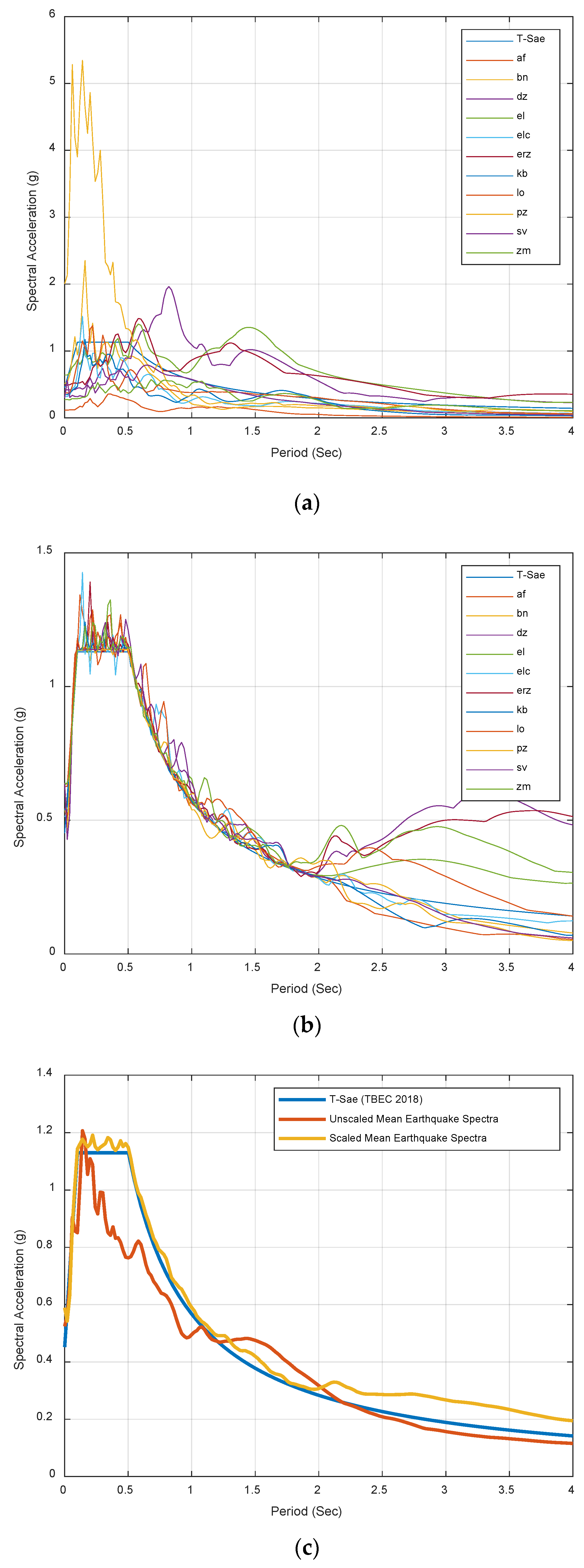
1] provisions for Site Class ZD and 5% damping ratio. Each record was adjusted to the target response spectrum using a least-squares spectral matching algorithm over the period range of 0.1–1.0 s, which corresponds to the fundamental period range of the tested specimens (
Figure 4). The amplitude scaling factor for each record was determined to achieve an equivalent design-level acceleration of 0.4 g at the effective period. The input motions were applied uniaxially along the longitudinal axis of the frames, with amplitudes increased incrementally until visible cracking and interface separation were observed. All records were executed sequentially in the same direction without simultaneous bi-directional input. The shake-table control system operated in displacement feedback mode, ensuring accurate reproduction of the target acceleration time histories within a tolerance of ±5%.
As illustrated in
Figure 4, the scaling process ensured a high level of compatibility between the scaled acceleration spectra and the design target spectrum. Subsequently,
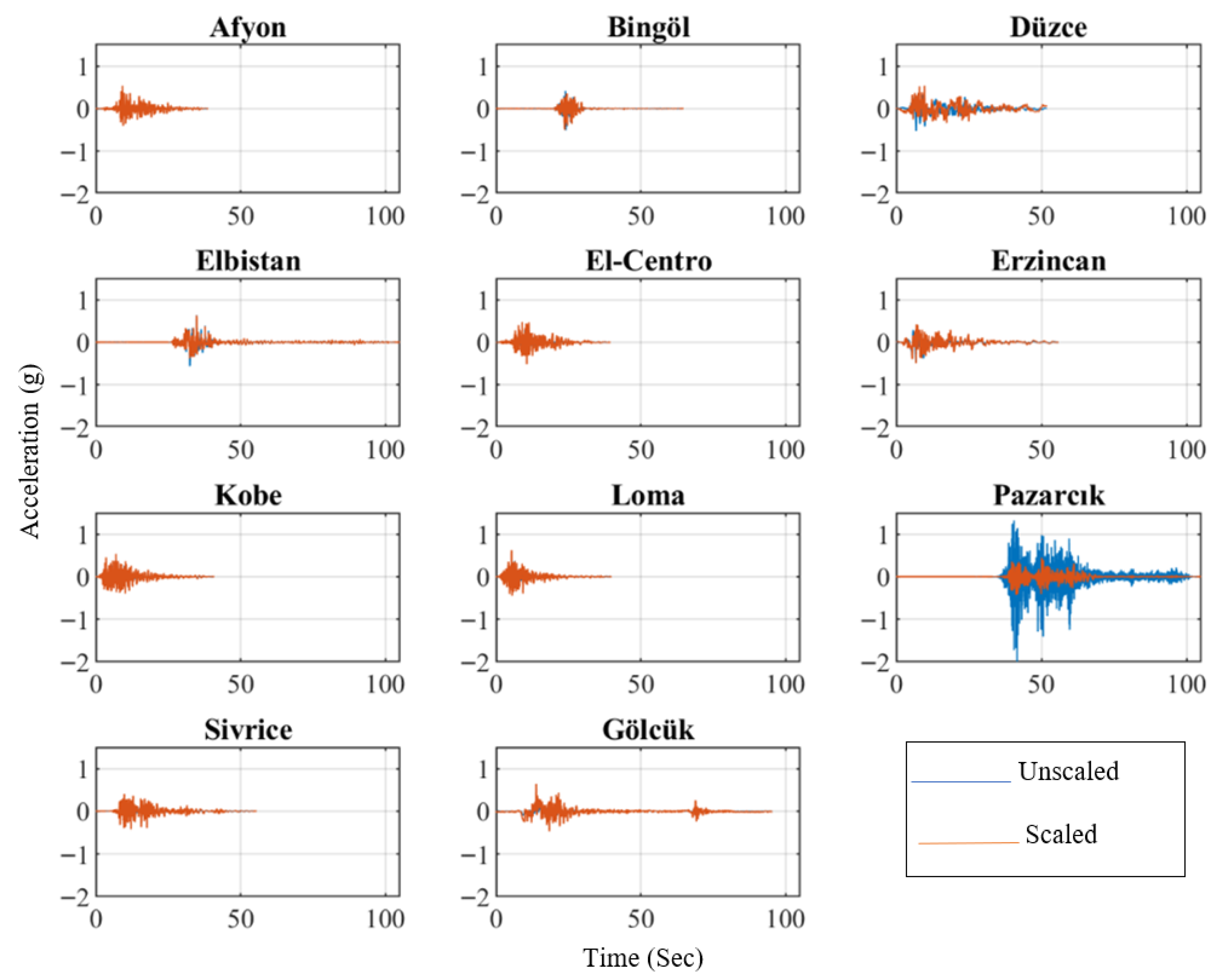
Figure 5 presents both the unscaled and scaled acceleration–time histories used in the experiments, clearly demonstrating the consistency of the amplitude and frequency contents after the scaling process. The selection of the Elbistan and Sivrice ground motions was based on their spectral characteristics, which are compatible with the range of the fundamental period of the tested frame systems. This frequency compatibility allows for the effective excitation of the dominant vibration modes and the proper evaluation of the stiffness degradation and the dominant frequency.
The abbreviations of the earthquakes presented in
Figure 5 are listed in
Table 4.
Figure 5 illustrates the horizontal elastic acceleration spectrum of the T–Sae model structures in accordance with the Turkish Building Earthquake Code [
1].
Figure 5. Comparison between the TBEC-2018 target design spectrum (5% damping, Site Class ZD) and the scaled acceleration spectra of eleven ground-motion records. The red curve represents the mean spectrum, and the shaded area corresponds to the ±1σ band. The close alignment over the 0.2–1.5 T period range confirms adequate compatibility between the scaled inputs and the target response spectrum.
The unscaled and scaled acceleration–time records presented in
Figure 6 were selected to provide a broad representation of seismic input motions with varying frequency contents and amplitude levels. Such diversity ensures that the dynamic response of infilled steel frames can be evaluated under both low- and high-frequency excitations, allowing a realistic simulation of structural behavior under different earthquake scenarios. The combined use of original and scaled ground motion records has been widely adopted in shake-table testing to capture nonlinear effects and verify scaling reliability [
59,
60]. The Pazarcık record (original PGA = 2.070 g) was amplitude-scaled to comply with the shake-table capacity and the test matrix target intensity. A scale factor of 0.19 was applied, yielding a platform-level PGA ≈ 0.40 g (uniaxial input). All accelerations reported herein refer to the platform level after scaling
All acceleration and displacement time histories recorded during the shake-table tests were processed prior to analysis. The raw signals were first detrended and subjected to baseline correction to eliminate low-frequency drift. A 4th-order zero-phase Butterworth band-pass filter with cut-off frequencies of 0.5–50 Hz was applied to remove noise while preserving the structural response range. The peak-picking method was used to determine the maximum acceleration and displacement responses from each test. For frequency-domain analyses, the signals were windowed using a Hanning function with 50% overlap and processed through a Fast Fourier Transform (FFT) to obtain the amplitude spectra. The dominant frequency was defined as the frequency corresponding to the maximum spectral amplitude within the primary vibration band. Outliers exceeding three standard deviations (±3σ) from the mean were excluded from the dataset, ensuring statistical consistency in the reported results. These processed datasets formed the basis for evaluating stiffness degradation and frequency variation trends throughout the excitation sequence.
3. Results and Discussion
In this section, the dynamic behaviors of steel frames with different joint configurations and mortar types were evaluated based on the data obtained from shake-table experiments. Acceleration, displacement, and spectral response records were comparatively analyzed to reveal the performance differences between rigid and flexible joint systems. The results indicated that both the joint configuration and the mortar type play a significant role in determining the seismic response of the frame. Additionally, variations in stiffness, peak displacement, and acceleration responses were assessed and discussed in comparison with related studies in the literature.
3.1. Dynamic Response of the Steel Structures
In the experimental program, the seismic responses of the steel frames with different joint types (rigid and flexible) and mortar materials (traditional and geopolymer) were examined separately in both in-plane and out-of-plane directions. The peak acceleration and displacement values were analyzed to identify the effects of joint stiffness and infill–mortar interaction on the dynamic behavior of the frames.
The in-plane peak acceleration values were analyzed to evaluate the stiffness differences among the models and the influence of the infill–mortar interface on the frame behavior.
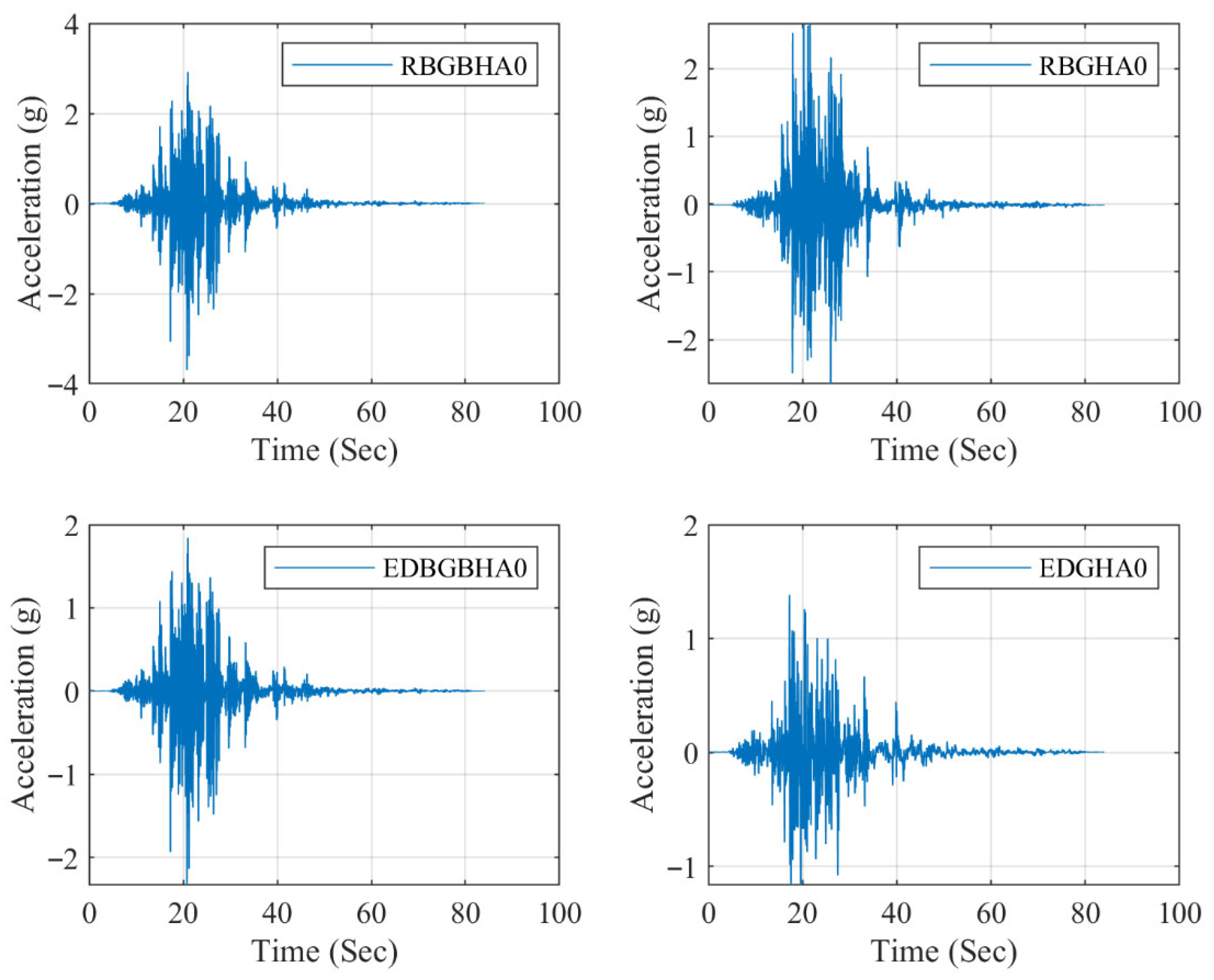
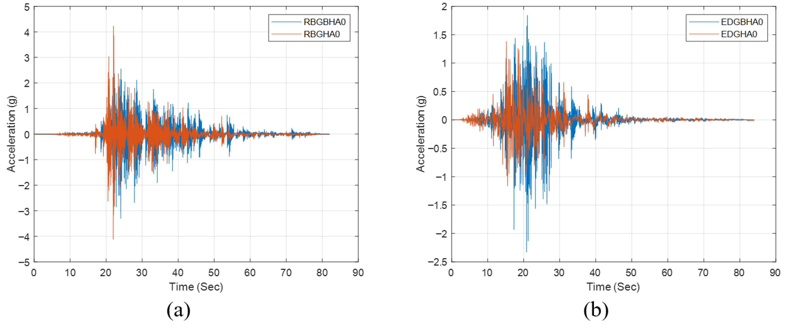
Figure 6 compares the maximum in-plane accelerations for all four models (RBGBHA0, RBGHA0, EDGBHA0, and EDGHA0). The results indicate that rigidly connected frames (RBGHA0 and RBGBHA0) exhibit higher peak accelerations than flexibly connected ones, primarily due to the stronger confinement effect provided by the infill walls. Although both traditional and geopolymer mortars produced similar overall patterns, geopolymer-based frames exhibited approximately 8–12% higher acceleration values.
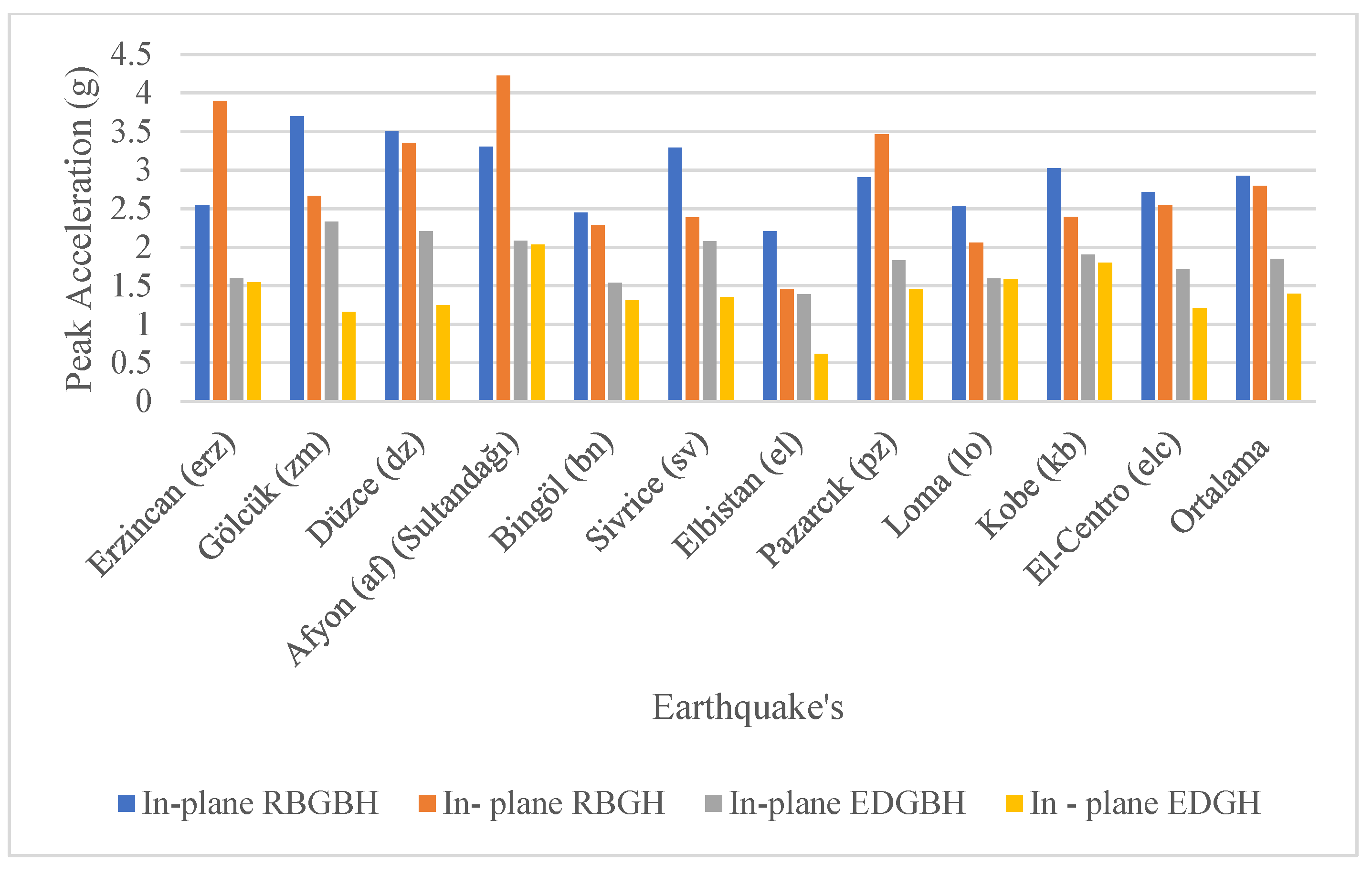
Figure 7 presents the comparison of in-plane peak acceleration values for the four frame configurations (RBGBH, RBGH, EDGBH, and EDGH) under the maximum effective earthquake scenario. The results indicate that the rigidly connected frames (RBGBH and RBGH) exhibited significantly higher acceleration amplitudes than the flexible joint models (EDGBH and EDGH). This difference can be attributed to the stronger anchorage of the infill walls in the rigid systems, which increased the overall stiffness and transferred the seismic energy more directly to the frame members. In the geopolymer mortar models, the enhanced bonding between the infill and the steel frame increased the system’s natural frequency, leading to slightly higher acceleration amplitudes. Particularly, the RBGH configuration reached peak acceleration values up to 0.82 g, demonstrating the stiff response induced by the geopolymer mortar. On the other hand, the flexible-joint frames, especially the EDGH model, exhibited reduced stiffness due to the intentional gap between the infill and the frame, allowing partial deformation capacity and lower acceleration amplitudes. These findings are consistent with previous studies, which reported that rigidly connected infill walls tend to amplify acceleration responses, whereas flexible connections improve ductility and reduce force transmission [
12,
25,
61]. The current results therefore confirm that using geopolymer mortars enhances frame–infill interaction by increasing overall system stiffness while maintaining favorable seismic performance.
Out-of-plane excitation plays a significant role in defining the lateral stiffness and infill–frame interaction.
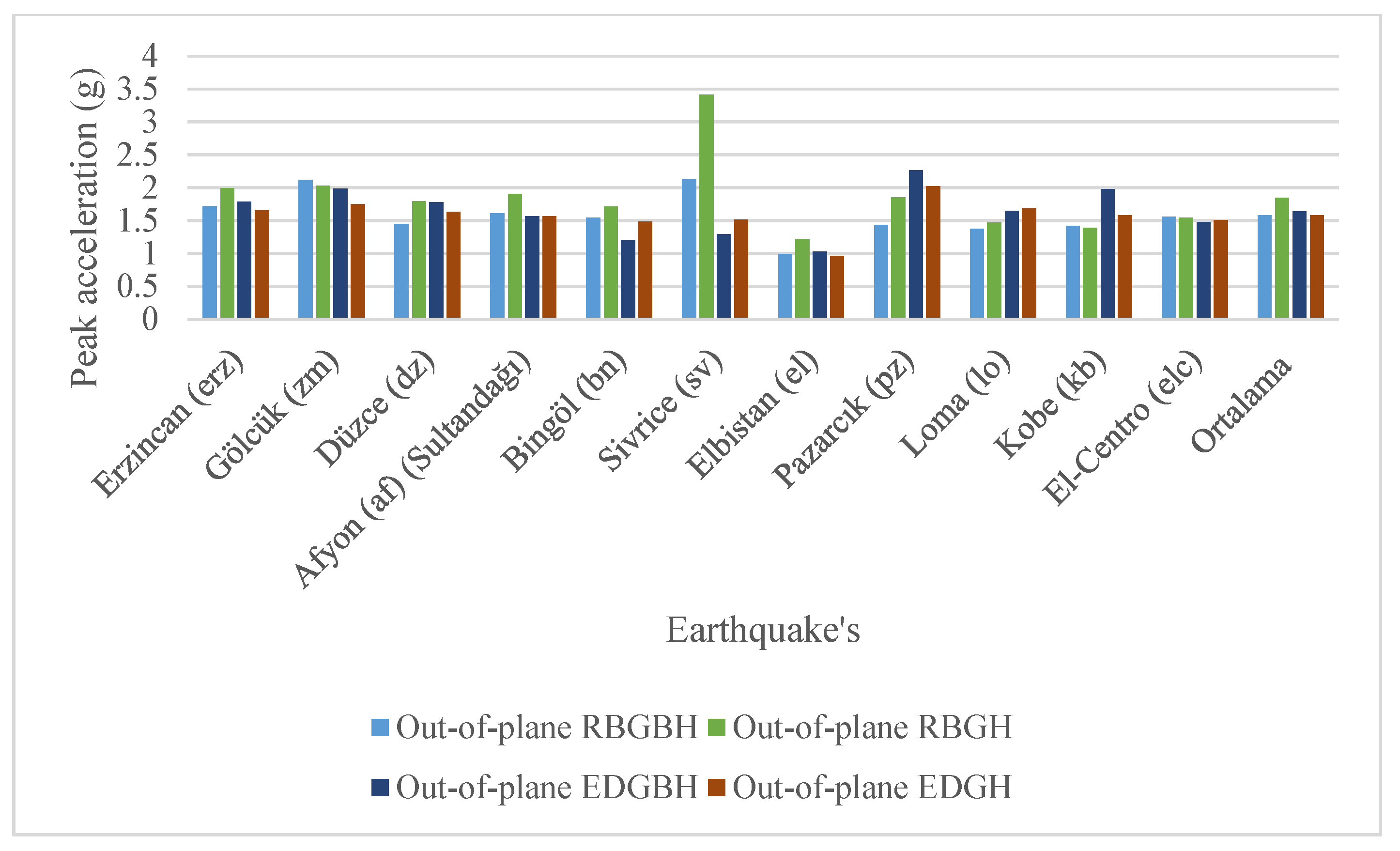
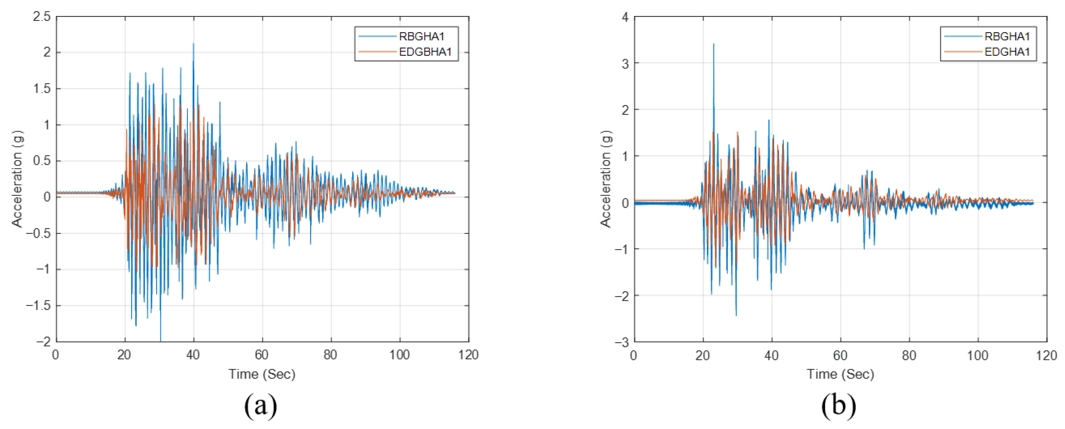
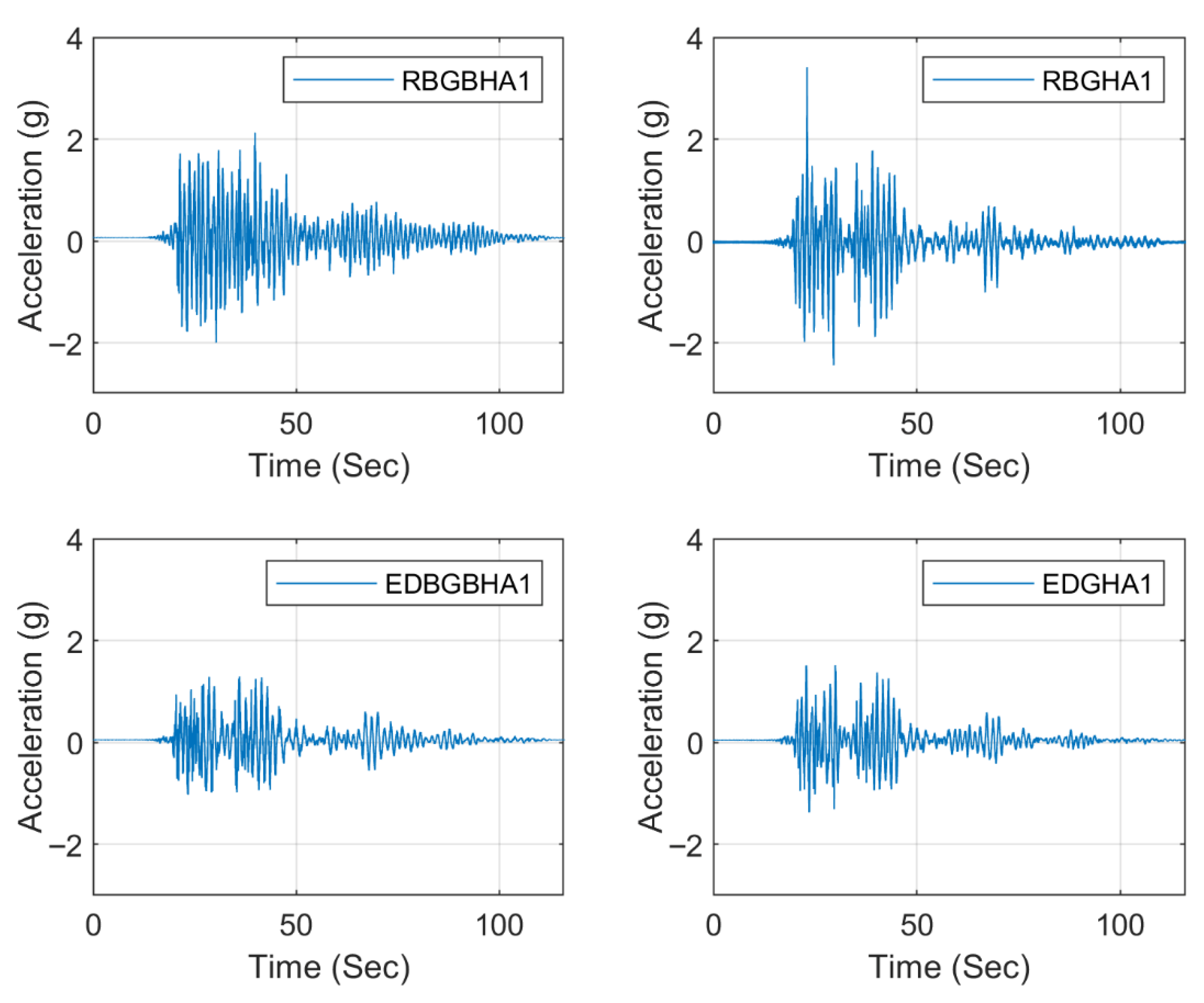
Figure 8 illustrates the comparison of out-of-plane peak acceleration values for all frame configurations. The results reveal that rigid joint models exhibit approximately 20% higher acceleration responses compared to flexible joint systems, which can be attributed to the strong connection of the infill walls to the surrounding steel frame. In geopolymer mortar systems, the enhanced bonding between the infill and the frame effectively limited vibration amplitudes.
Under the maximum effective earthquake scenario, the data presented in
Figure 9 show that flexible joint configurations produced lower acceleration amplitudes than rigid joint ones. Particularly, the EDGH model exhibited the lowest vibration amplitudes among all configurations. The out-of-plane response results reveal that the interaction between the infill walls and the steel frame is highly dependent on the joint configuration. In rigid joint systems, the tight bonding of the walls to the frame caused a greater portion of the seismic energy to be transmitted to the structural members, leading to higher peak acceleration values. Conversely, the flexible joint configurations allowed partial decoupling between the wall and the frame, effectively limiting the energy transfer and reducing acceleration amplitudes. This behavior becomes particularly critical under near-fault earthquake conditions. Similarly, Sarno et al. (2021) and Furtado et al. (2020) reported that flexible connection details can mitigate out-of-plane wall damage by reducing overall lateral stiffness and constraining stress concentrations [
25,
62].
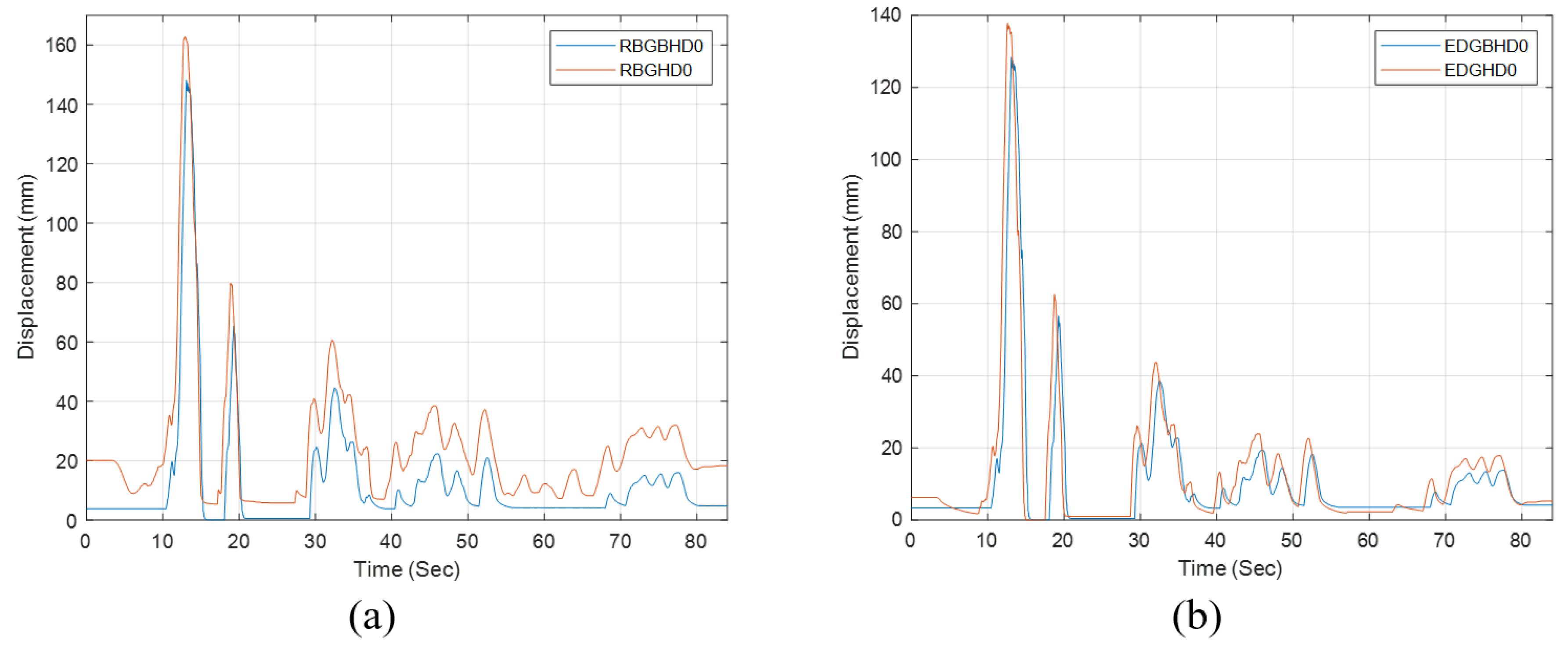
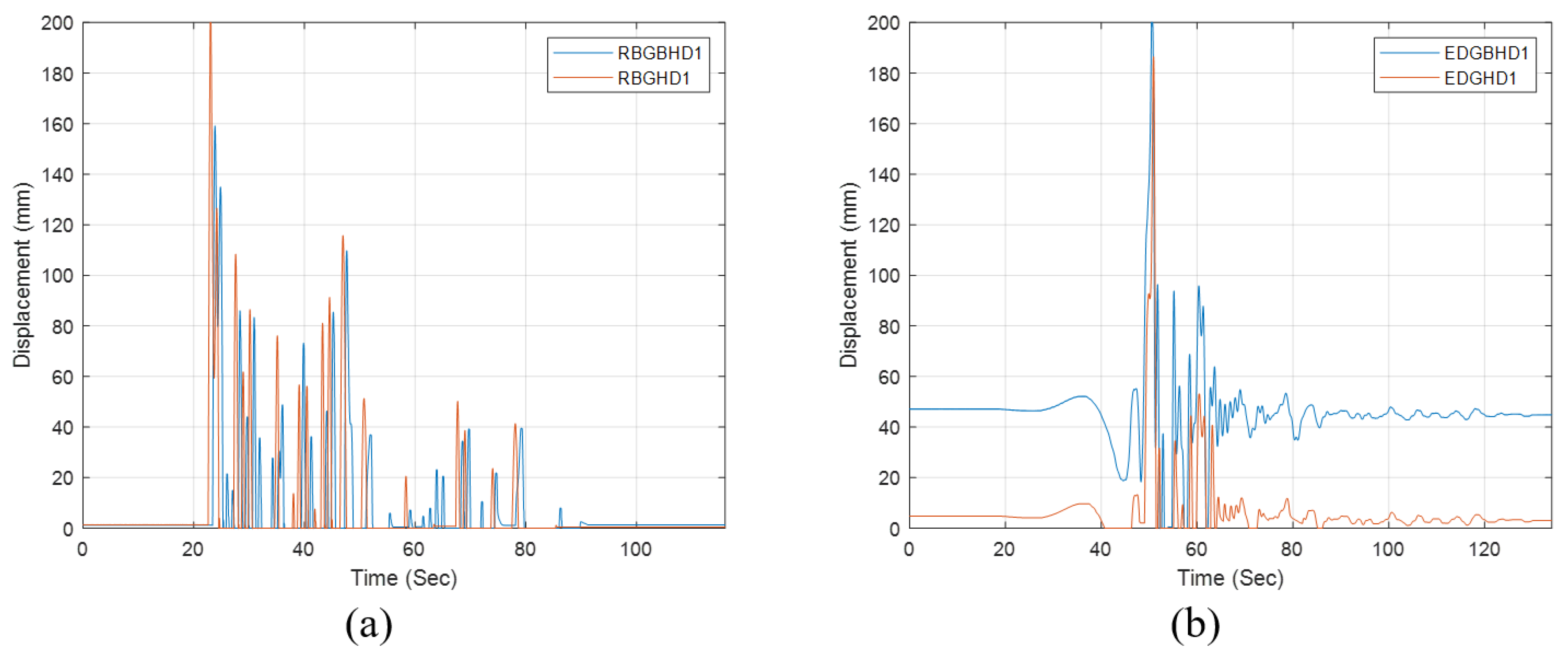
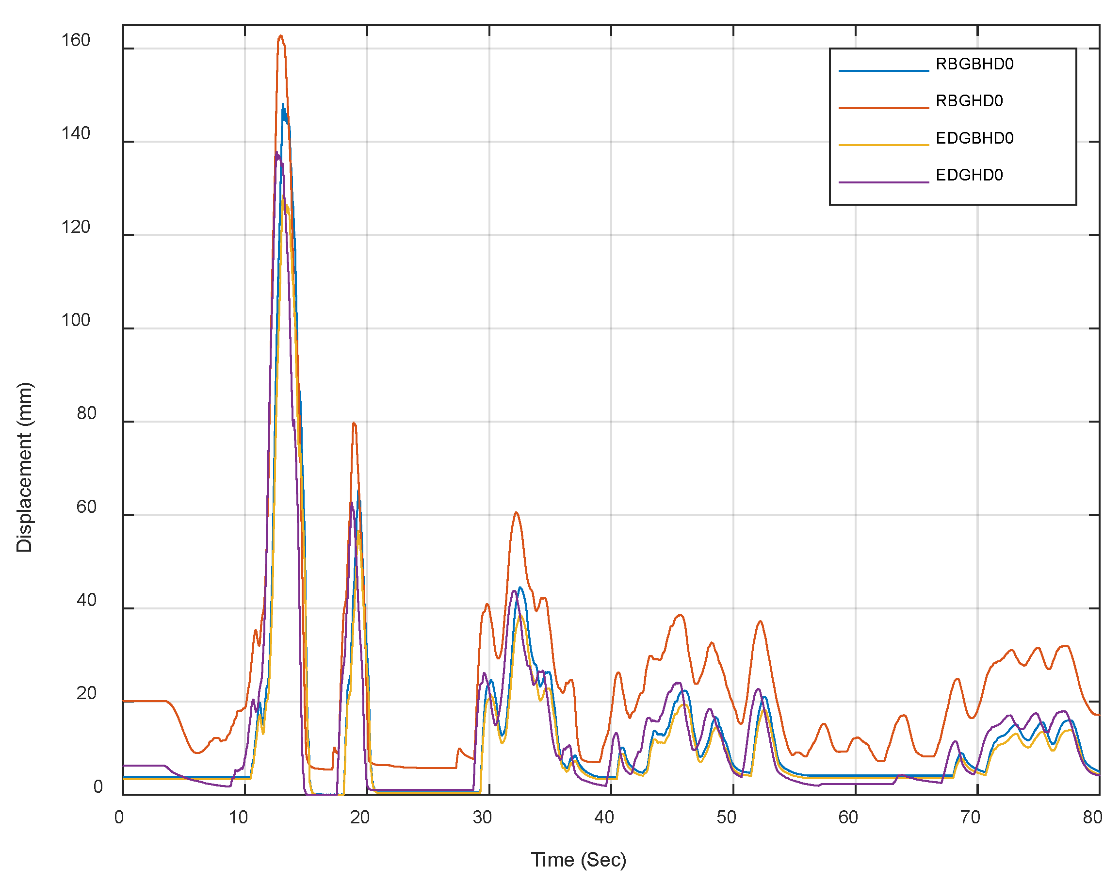
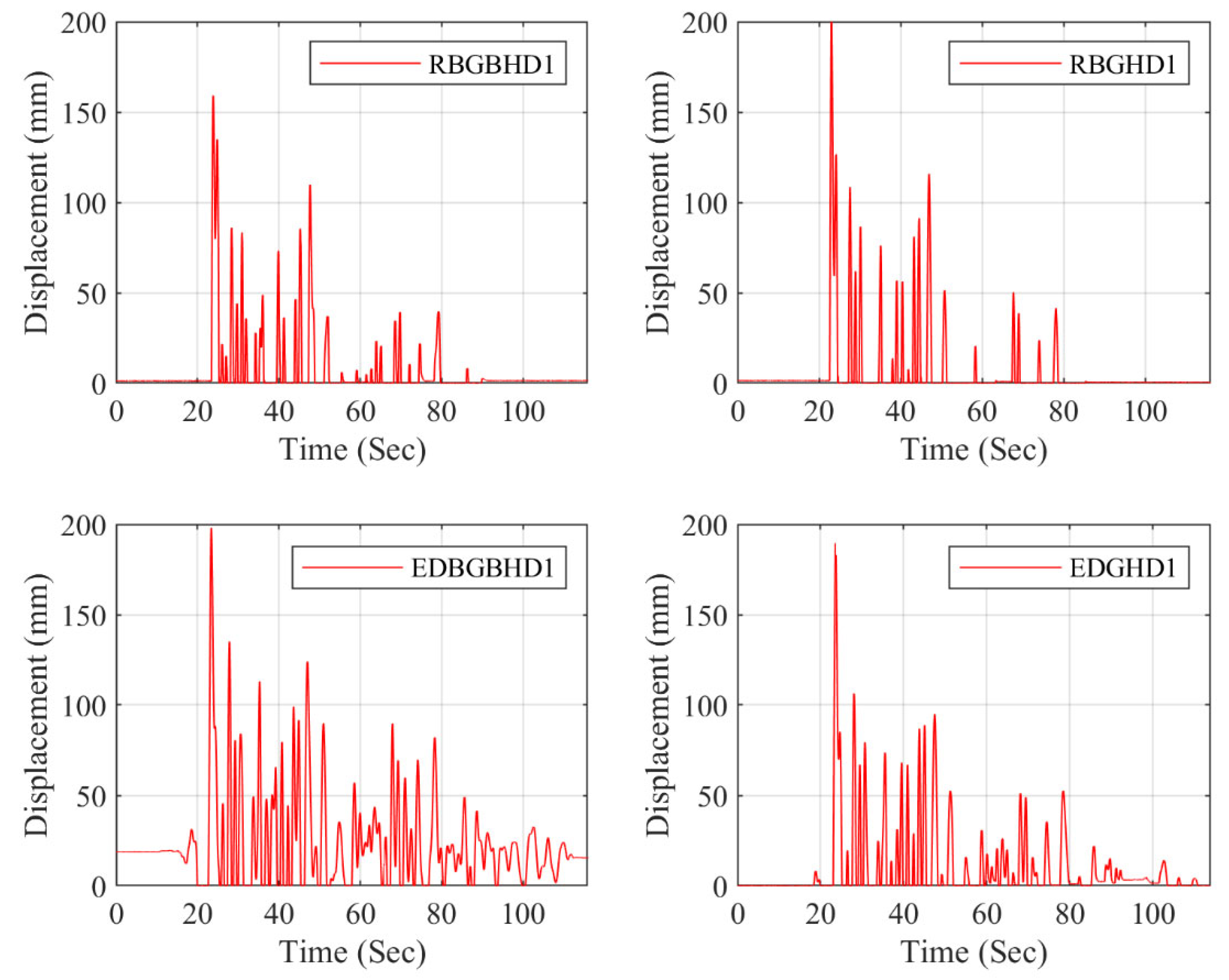
In this study, experimental analyses were performed under 11 different earthquake ground motions to investigate the in-plane deformation behavior of the steel frames. Among all ground motion records, the 2023 Elbistan earthquake generated the highest displacement amplitudes. Due to its high moment magnitude (Mw = 7.6), long-period components, and broad spectral energy content, this record induced the most significant lateral deformations in the test models. Therefore, the Elbistan earthquake was adopted as the reference ground motion, and the in-plane displacement comparisons were primarily based on this record. As illustrated in
Figure 10, the displacement results obtained under the Elbistan earthquake are compared for all frame configurations. The rigid joint systems (RBGBH and RBGH) exhibited relatively smaller displacements, whereas the flexible joint systems (EDGBH and EDGH) showed noticeably larger deformations due to the separation gap between the frame and infill, which enhances the overall ductility and lateral deformation capacity. Moreover, geopolymer mortar models demonstrated approximately 10% lower displacement amplitudes compared to conventional mortar models, attributed to the superior adhesion and bonding strength at the frame–infill interface.
The out-of-plane behavior of the steel frame–infill systems was evaluated using displacement records obtained under 11 different earthquake ground motions. The comparisons indicate that the 2020 Sivrice earthquake produced the maximum out-of-plane displacements. This result is attributed to the Sivrice record’s frequency content overlapping the out-of-plane dominant vibration range of the specimens and its sufficient acceleration amplitude, which collectively amplified the transverse deformation response (i.e., partial resonance/strong modal participation). As presented in
Figure 11, the out-of-plane peak displacements under the Sivrice event are compared across all models. The rigid joint configurations (RBGBH, RBGH) exhibited relatively limited displacements, whereas the flexible joint systems (EDGBH, EDGH) showed increased values due to reduced interface constraints. Moreover, geopolymer mortar specimens produced smaller out-of-plane displacements than conventional mortar counterparts, consistent with improved bonding at the frame–infill interface.
3.2. Effects of Shear Studs and Geopolymer Mortars on Seismic Behavior
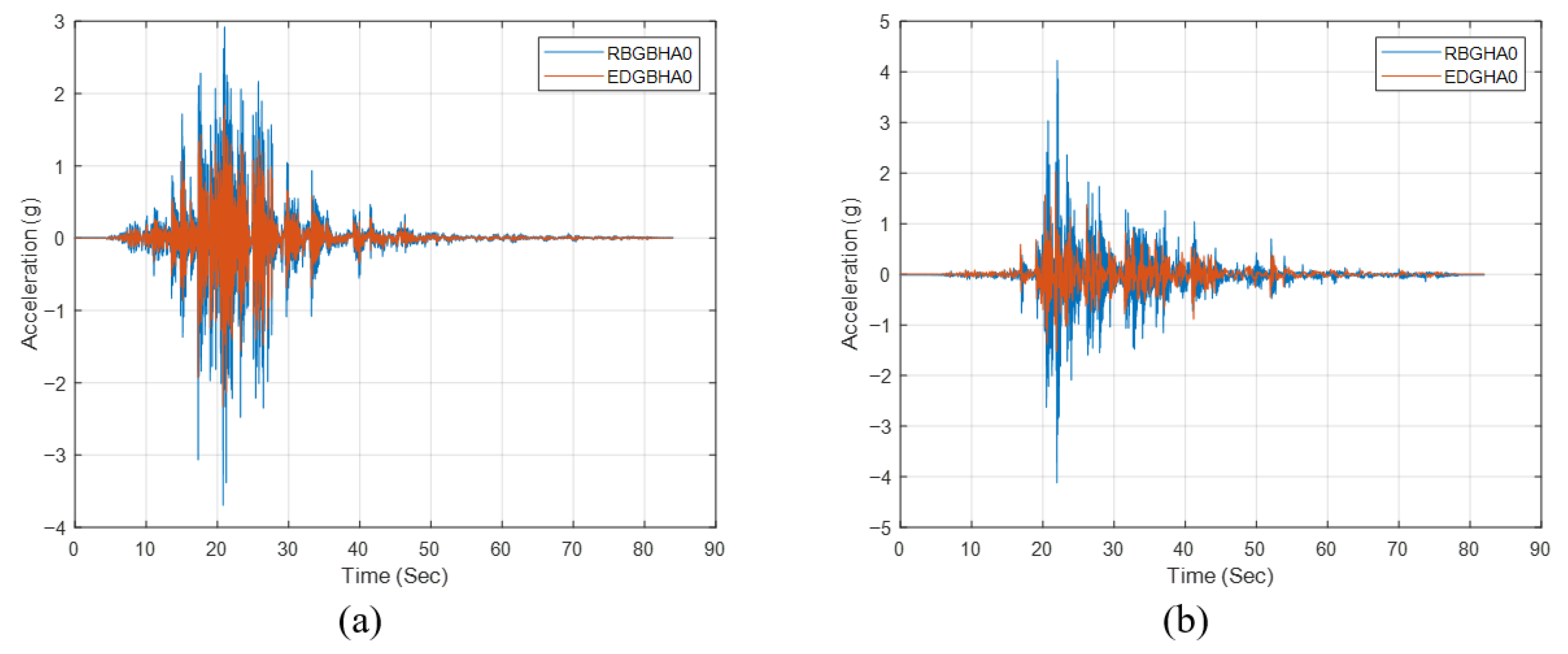
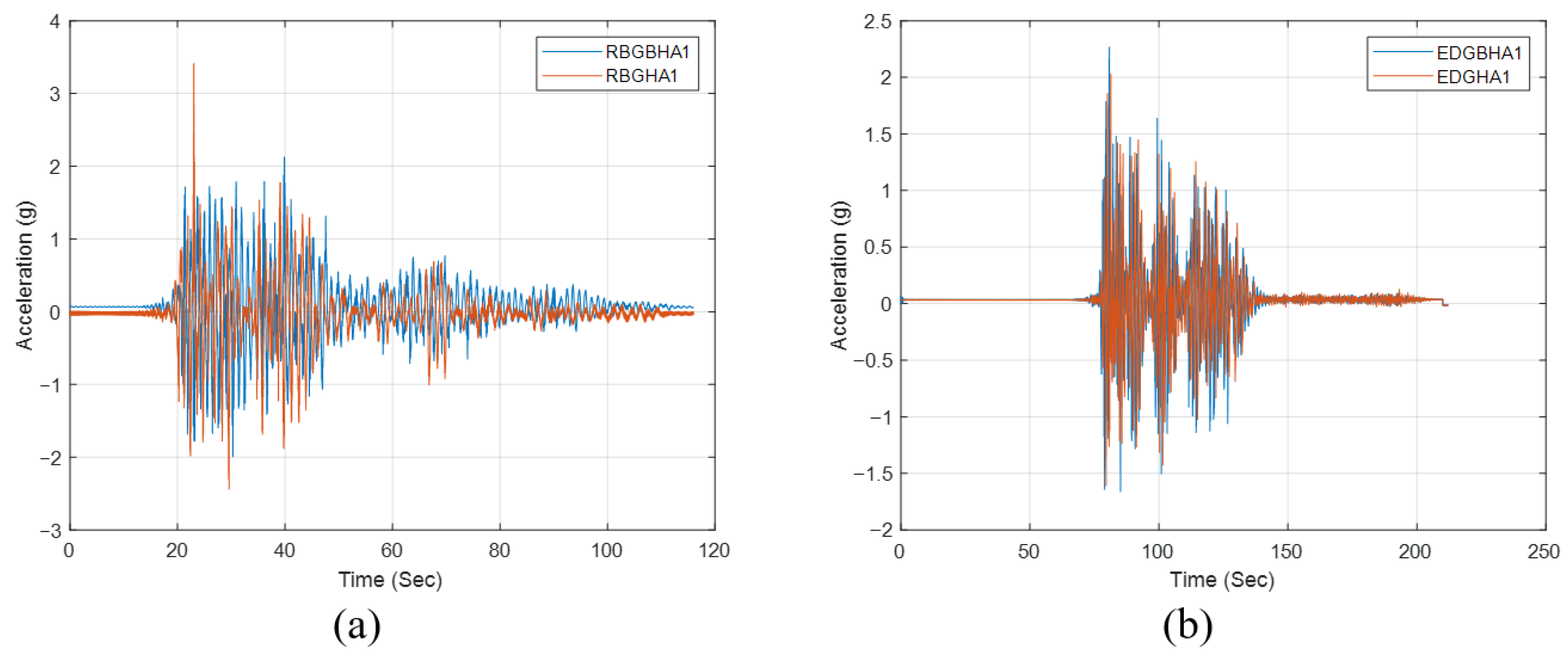
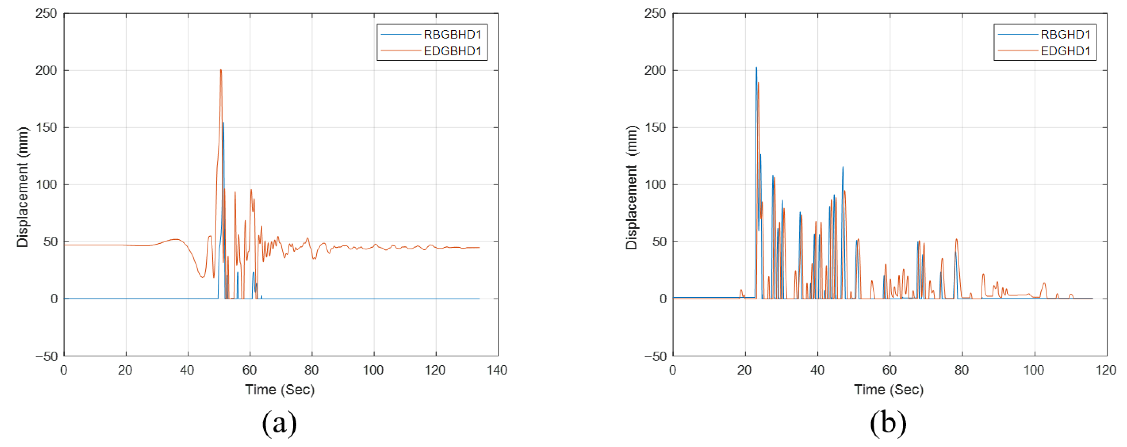
Under in-plane loading, shear studs were found to restrict the interface slip between the infill wall and the steel frame, thereby enhancing the overall stiffness of the system. Experimental findings indicated that for conventional mortar, replacing shear studs with flexible joints reduced the peak acceleration values by approximately 48.40%, whereas for geopolymer mortar, the reduction reached 52.38%. These results demonstrate that shear studs are more effective when used with geopolymer mortars. Due to their higher bond strength and better adhesion, geopolymer mortars facilitated more efficient stress transfer through the studs, resulting in higher stiffness and smaller lateral deformations. In contrast, conventional mortars provided weaker bonding, leading to a less pronounced improvement. As illustrated in
Figure 12a, shear studs in geopolymer mortar models decreased peak accelerations by about 52%, while
Figure 12b shows that the reduction in conventional mortar models was about 48%. This comparison confirms that the performance of shear studs is directly dependent on the mortar–interface interaction, with geopolymer mortars significantly enhancing this interaction.
In-plane displacements were evaluated considering the influence of joint configuration and frame stiffness. The results indicated that removal of shear studs reduced stiffness and increased displacement amplitudes. The increase was approximately 48% for conventional mortar models and 52% for geopolymer mortar models. The superior bonding of geopolymer mortars provided a more efficient stress transfer at the interface, contributing to lower deformation levels, whereas the effect of studs in conventional mortars was relatively limited.
Figure 13a represents the conventional and
Figure 13b the geopolymer mortar systems.
Out-of-plane peak accelerations were analyzed to evaluate the influence of shear studs on the dynamic response of the wall–frame interaction. The results revealed that removal of shear studs decreased overall stiffness and significantly increased acceleration amplitudes. The peak acceleration increased by approximately 41% for conventional mortars and 45% for geopolymer mortars. This outcome indicates that the studs enhanced bond strength at the wall–frame interface, limiting interfacial slippage. The effect was more pronounced for geopolymer mortars due to their superior adhesion and stiffness characteristics.
Figure 14a shows the conventional and
Figure 14b the geopolymer mortar systems.
Out-of-plane displacements were compared to evaluate the influence of shear studs on stiffness and deformation capacity. In models without shear studs, the bond between the steel frame and the infill wall weakened, leading to larger displacement amplitudes. The increase was measured as 46% for conventional mortar models and 49% for geopolymer mortar models. These findings indicate that shear studs enhance the bond strength at the wall-frame interface and limit out-of-plane vibrations. Due to their superior adhesion, the effect of shear studs was more pronounced in geopolymer systems.
Figure 15a,b illustrate the observed differences for conventional and geopolymer mortar models, respectively.
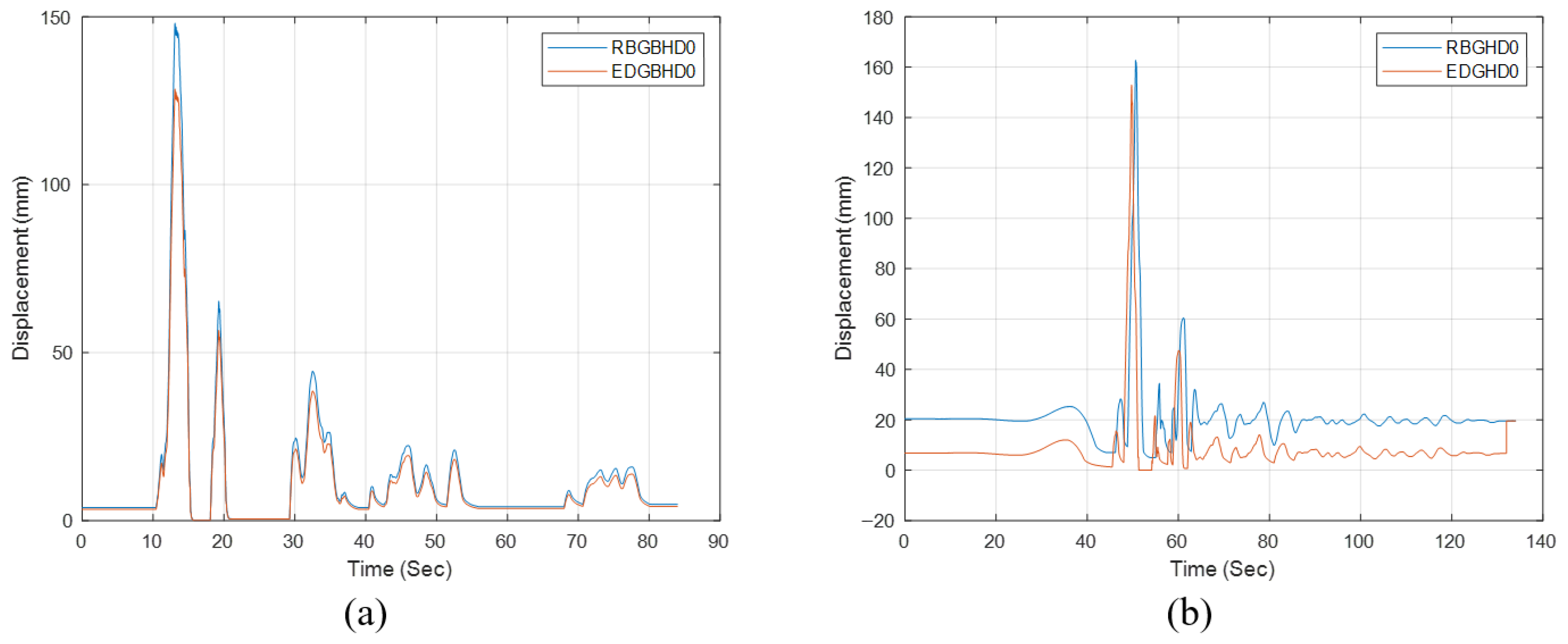
In-plane shaking table tests were conducted to evaluate the influence of geopolymer mortars under rigid and flexible joint conditions. In the rigidly connected models, the use of geopolymer mortars increased the peak acceleration values by approximately 34.9% compared with conventional mortars. This behavior is attributed to the higher stiffness of geopolymer mortars, which enhanced the overall rigidity of the system and resulted in a more abrupt transfer of seismic energy. Conversely, in flexible joint configurations, the application of geopolymer mortars reduced the peak acceleration by nearly 27.8%, indicating a more efficient deformation capacity mechanism. The flexible joints allowed controlled interaction between the infill wall and the steel frame, thus mitigating acceleration demand.
Figure 16a presents the results for rigid connections, while
Figure 16b illustrates flexible joints.
In-plane displacements were analyzed considering both joint configuration and mortar characteristics. In rigid connections, the use of geopolymer mortars increased the overall stiffness but limited the deformation capacity, leading to an approximate 12.3% increase in displacements. This was attributed to the higher elastic modulus and lower deformation tolerance of geopolymer mortars. For flexible joints, geopolymer mortars facilitated better deformation capacity at the interface, though their influence on deformation capacity remained modest. In this configuration, displacements increased by about 9.4%. Overall, geopolymer mortars enhanced stiffness and acceleration response in rigid systems, while allowing more controlled deformation in flexible ones.
Figure 17a shows the rigid joint configuration, and
Figure 17b illustrates the flexible joint configuration.
Out-of-plane peak acceleration values were examined to assess the influence of geopolymer mortars under rigid and flexible joint configurations. In the rigid connection models, the use of geopolymer mortars increased system stiffness and caused a 13.4% rise in peak accelerations, mainly due to their higher elastic modulus and stiffer mechanical behavior. In contrast, for flexible joints, geopolymer mortars contributed to greater deformation capacity by moderating the interaction between the infill wall and the steel frame, resulting in an approximately 7.8% reduction in peak accelerations. This finding indicates that flexible configurations promote a more ductile response and allow seismic energy to be distributed more gradually.
Figure 18a presents the rigid joint configuration, while
Figure 18b shows the flexible joint configuration for out-of-plane peak acceleration comparisons.
Out-of-plane displacement results were analyzed to compare the deformation behavior of geopolymer mortars in rigid and flexible joint configurations. In rigidly connected models, the use of geopolymer mortars increased stiffness, thus restricting deformation and reducing displacements by approximately 10.6%. This behavior is associated with the higher elastic modulus of geopolymer mortars, which enables faster energy transfer and smaller deformation amplitudes. Conversely, in flexible joints, geopolymer mortars partially limited the infill wall–frame interaction while enhancing the system’s deformation capacity, leading to an approximately 8.9% increase in displacements. This indicates that flexible connections allowed more freedom for infill wall deformation to develop under seismic excitation.
Figure 19a represents the rigid connection configuration, while
Figure 19b shows the flexible joint configuration.
3.3. Frequency Domain Analysis
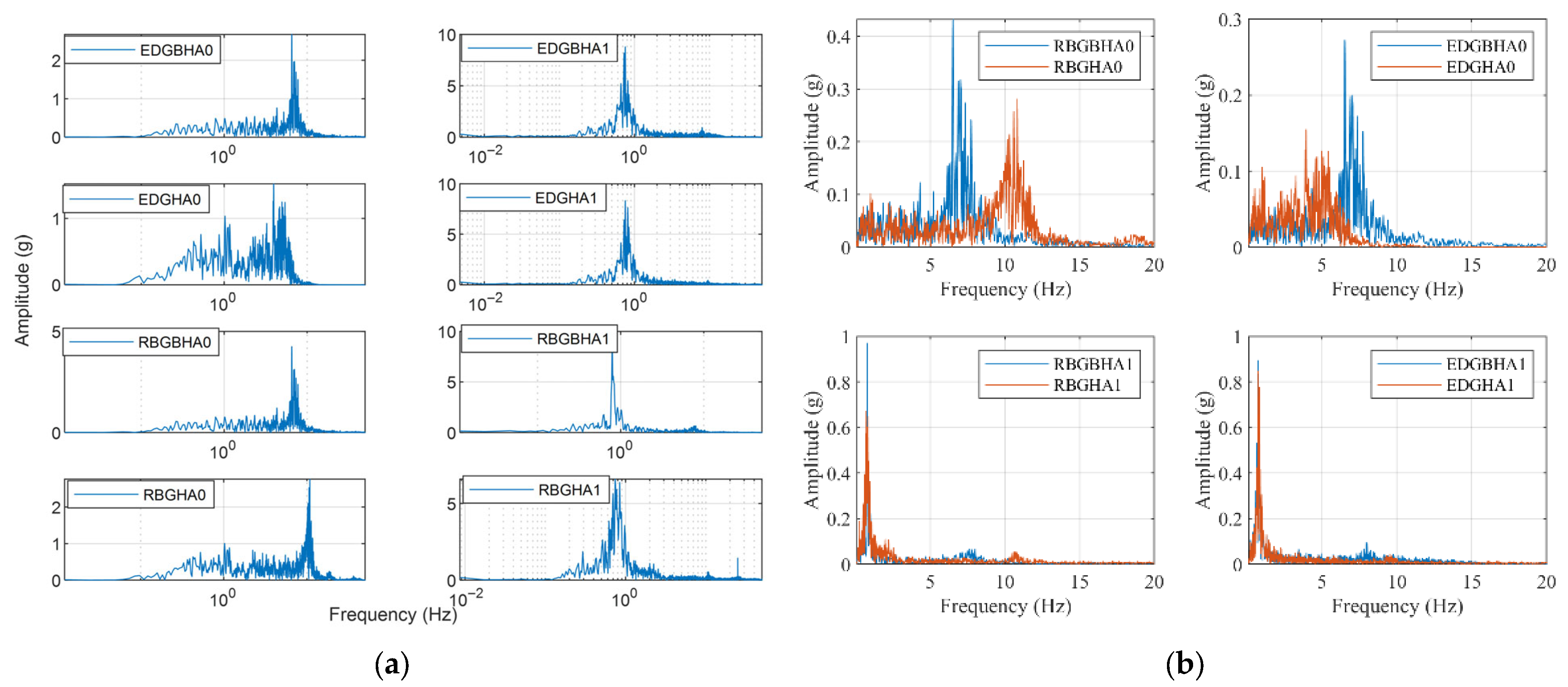
Frequency-domain analyses were conducted for four infilled steel frame models with different connection configurations under 11 recorded earthquake ground motions. For each model, dynamic parameters were obtained within the scope of forced vibration analysis using the ground motion that produced the maximum peak acceleration response. The rigidly connected conventional mortar frame (RBGBH) was analyzed using the Gölcük earthquake record for both in-plane and out-of-plane directions. The rigidly connected geopolymer mortar frame (RBGH) employed the Afyon record for the in-plane case and the Sivrice record for the out-of-plane case. The flexible-jointed conventional mortar frame (EDGBH) was analyzed under Gölcük (in-plane) and Pazarcık (out-of-plane) earthquakes, while the flexible-jointed geopolymer mortar frame (EDGH) was examined under Afyon (in-plane) and Pazarcık (out-of-plane) excitations.
As shown in
Figure 20, Fourier amplitude spectra were obtained for the 0.1–50 Hz frequency range. In the in-plane direction, the dominant frequencies were calculated as 6.53 Hz (RBGBH), 10.84 Hz (RBGH), 6.53 Hz (EDGBH), and 3.96 Hz (EDGH). The use of geopolymer mortar in rigidly connected frames increased the dominant frequency by 39.76%, indicating a stiffer structural behavior. Conversely, when applied to flexible-jointed frames, geopolymer mortar reduced the dominant frequency by 39.35%, resulting in a more flexible configuration. The conventional mortar had negligible effect on the frequency in both cases. Overall, introducing flexible joints decreased the dominant frequency by 63.46%, effectively increasing the natural period and enhancing the deformation capacity of the frame. In the out-of-plane direction, dominant frequencies were approximately 0.79 Hz (RBGBH), 0.79 Hz (RBGH), 0.75 Hz (EDGBH), and 0.75 Hz (EDGH), showing no significant variation between models.
Based on LVDT displacement readings, the maximum interstory drift ratios ranged between 0.45% and 0.72%, indicating moderate deformation capacity. Progressive reductions in dominant frequency were also observed, reflecting stiffness degradation during dynamic excitation.
3.4. Integrated Assessment of Dynamic and Spectral Responses in Infilled Steel Frames
The overall seismic performance of the infilled steel frames was evaluated by correlating the experimental peak accelerations, dynamic displacements, and frequency-domain responses. The results indicate that both joint configuration and mortar type significantly influence the global dynamic behavior of the frames. Rigidly connected systems exhibited higher stiffness and peak acceleration responses, whereas flexible-jointed configurations allowed more controlled displacement and improved energy dissipation.
In the in-plane direction, the maximum acceleration was obtained from the Gölcük and Afyon records for conventional and geopolymer mortars, respectively. Flexible-jointed frames reduced peak acceleration values by up to 10%, confirming the damping contribution of joint separation. In contrast, rigid joints increased accelerations by approximately 13%, mainly due to the limited deformation capacity. Displacement analyses revealed that geopolymer mortars increased stiffness in rigid connections but reduced displacement amplitudes by around 10.6%, whereas in flexible joints, the same mortars enhanced deformation capacity and resulted in a moderate 8–9% rise in displacement values. These findings are consistent with previous studies emphasizing that flexible interfaces and advanced mortars can enhance ductility and delay failure mechanisms in infilled systems [
25,
28,
43].
In the out-of-plane direction, the highest accelerations were generated during the Sivrice and Pazarcık earthquakes. The flexible-jointed geopolymer system (EDGH) achieved the lowest acceleration and displacement responses, showing reductions of approximately 5–6% in out-of-plane accelerations compared with conventional mortars. This outcome confirms the ability of flexible interfaces and geopolymer mortars to moderate out-of-plane vibration amplitudes, reducing the likelihood of brittle cracking in infill walls [
44,
63].
The frequency-domain analyses further reinforced the dynamic findings obtained from acceleration and displacement data. Geopolymer mortars in rigid systems increased the dominant frequency by 39.76%, indicating a stiffer behavior, whereas in flexible joints they decreased it by 39.35%, extending the natural period and improving ductility. These observations are consistent with Beyen (2021), who performed wavelet-based time–frequency analyses to assess structural damage and identified that reductions in dominant frequency are directly associated with stiffness degradation and deformation capacity characteristics [
64]. Similarly, in this study, shifts in dominant frequency values reflected the structural stiffness evolution under seismic excitations. The integrated interpretation of these outcomes demonstrates a strong relationship between increased frequency and acceleration amplitude in rigid systems, and enhanced deformation capacity with reduced acceleration in flexible configurations. Therefore, geopolymer mortars, when combined with flexible joints, provide an effective and sustainable method for improving seismic resilience while maintaining adequate ductility under cyclic loading.
In order to further clarify the phenomenon of peak acceleration amplification, analytical research on the absolute maximum dynamic response can provide valuable theoretical background. In fact, according to research by Lotfollahi-Yaghin et al. (2015), it was demonstrated that the maximum dynamic response is not necessarily based on conventional assumptions, but instead on system stiffness and excitation characteristics [
65]. In this context, it is possible to understand that the phenomenon of increased peak acceleration amplification, as recorded within rigid configurations, could be explained by changes to the response envelope, based on system stiffness.
In fact, recent research on system-level dynamic demands, including soil-structure interaction and pounding effects, as described by Bagheri et al. (2025), highlights that ground motion frequency content and changes to structural stiffness can play a significant role in defining amplification patterns, including envelopes of response [
66]. In this context, it is possible to understand that the selected records provide a consistent basis for defining the phenomenon of dynamic behavior, based on resilience.
The observed differences among configurations can be explained by the interaction mechanisms between the steel frame, mortar, and infill wall. In rigid-jointed specimens, the welded shear studs provided strong mechanical interlocking between the steel and masonry, effectively restricting interface slip. This restraint increased overall lateral stiffness, leading to higher acceleration peaks and slightly reduced deformation capacity. In contrast, flexible joints allowed limited sliding and separation at the frame–infill interface, which reduced force transfer and consequently lowered acceleration demands while permitting larger displacements. The geopolymer mortar altered this balance by enhancing the bond quality at the steel–masonry interface without excessively increasing stiffness. Its denser microstructure and improved adhesion provided a more uniform stress transfer mechanism, mitigating premature debonding and distributing shear more evenly along the joint. As a result, geopolymer–flexible systems exhibited reduced acceleration compared with conventional mortars, yet maintained sufficient deformability and minimal residual drifts. This behavior demonstrates that geopolymer mortars can serve as an effective intermediate solution, improving ductility and connection reliability without the over-stiffening effects typical of rigid joints.
The enhanced bonding properties of the geopolymer mortar systems may be explained through the micromechanical properties of the interface between the steel frame and the masonry. In comparison with cement-based mortars, the geopolymer binders are expected to produce a denser and more homogeneous structure of the aluminosilicate gel matrix [
8,
9], which may result in a reduction in the capillary pores and an optimization of the pore structure [
30,
38]. These properties are reported to enhance the quality of the interface contact and the ability of the interface to distribute the stress [
41]. From an interface mechanics point of view, the shear stress transfer between the steel frame and the masonry may be explained through the combination of mechanical interlocking, frictional resistance, and chemical adhesion properties [
20,
22,
23]. Therefore, the enhanced stiffness values and dominant frequencies of the rigid configurations may be explained through the efficient shear stress transfer between the interface. In the case of the flexible configurations, these properties may be responsible for efficient stress transfer and delayed debonding at the interface, as previously reported in other investigations on infilled frames [
25]. Nevertheless, detailed analysis of the microstructure is required to verify these interaction properties quantitatively.
To quantify variability across the 11 ground-motion records, the median, median absolute deviation (MAD), and 16–84% response bands were computed for both acceleration and displacement responses. Effect sizes between comparison pairs (e.g., rigid vs. flexible, conventional vs. geopolymer) were expressed as the difference in medians (Δ median) with 95% bootstrap confidence intervals. These statistical measures provide a clearer representation of the record-to-record variability and enhance the reliability of the observed performance trends.
3.5. Seismic Damage Evolution and Structural Performance Correlation
Shake table tests were conducted under in-plane and out-of-plane excitations on steel frame models with both rigid and flexible connections, utilizing either conventional or geopolymer mortars as infill bonding materials.
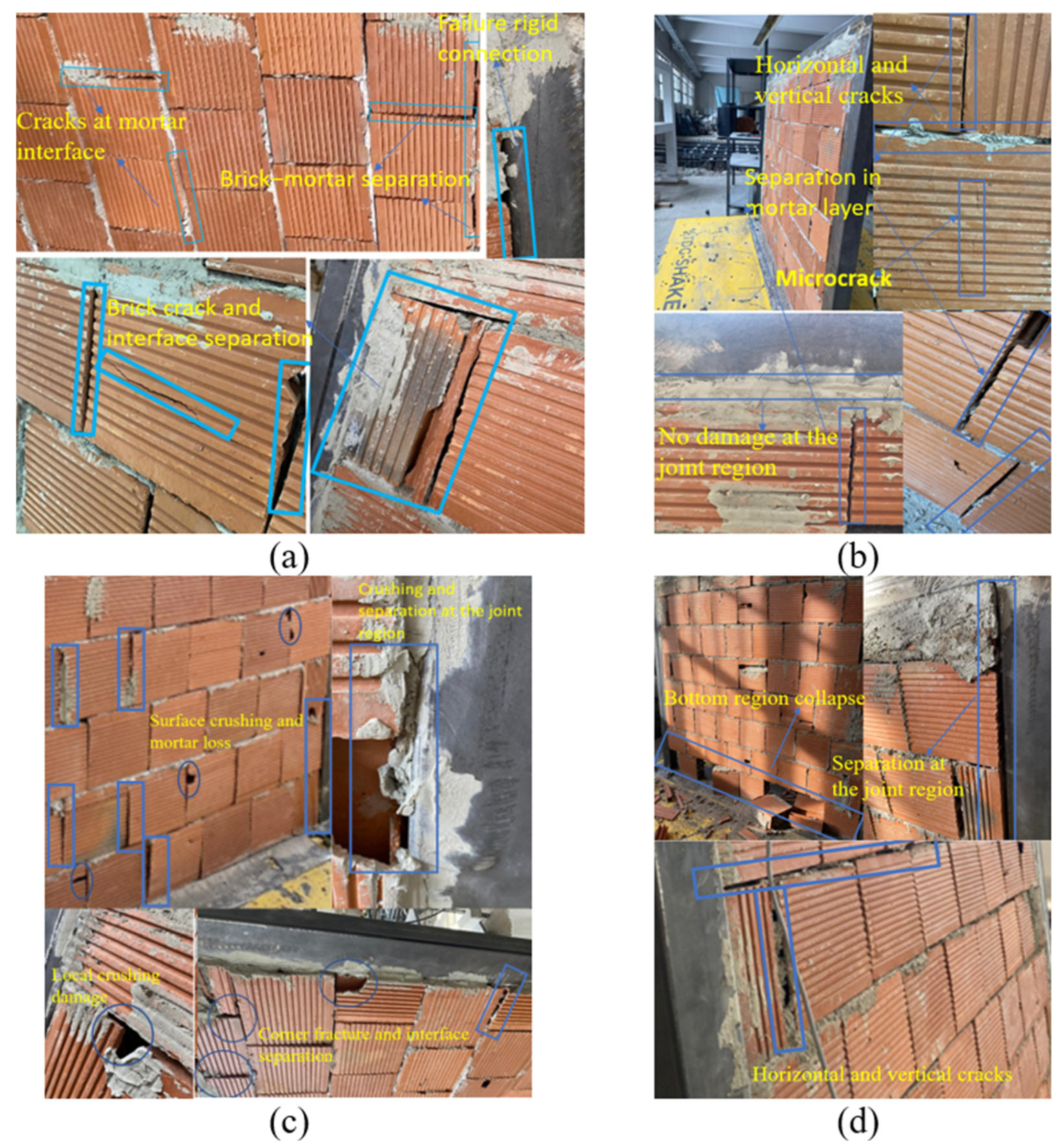
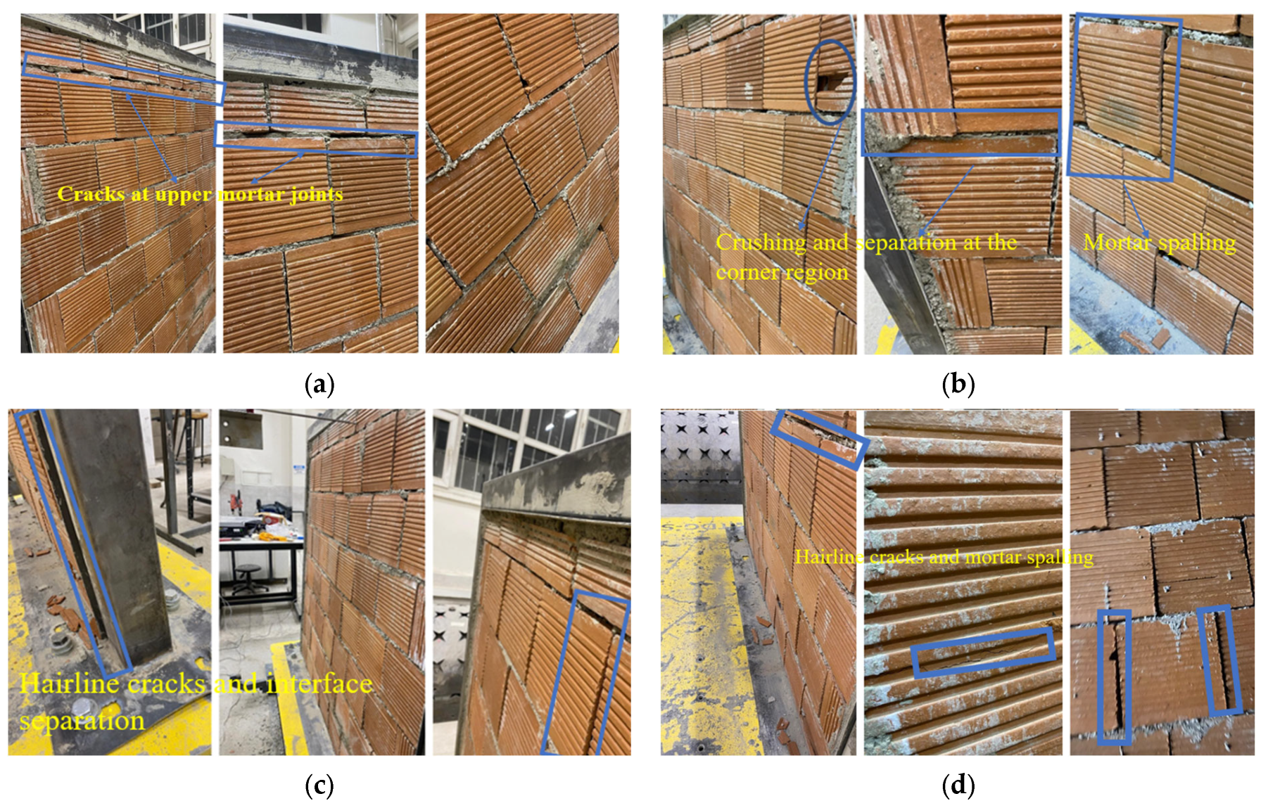
Figure 21a illustrates the in-plane damage patterns observed in the RBGBH model, which employed rigid joints with conventional mortar. Partial separation occurred at the column–wall interface, and fine cracks were visible in the mortar at the beam connections. Minor detachment and diagonal cracking were observed across the infill wall. Despite experiencing the highest peak acceleration among all specimens, no global collapse or severe structural degradation was recorded.
The EDGH model (
Figure 21b), which combined geopolymer mortar with flexible joints, showed almost no observable damage following the shaking test. The infill and the steel frame acted compatibly, with no visible signs of cracking, crushing, or separation at the interfaces. This observation confirms the positive influence of the geopolymer mortar–flexible joint combination in mitigating stress concentrations and enhancing seismic energy dissipation, consistent with the findings of Memari and Aliaari (2018) and Crisafulli (1997) [
20,
23]. In contrast, the rigidly connected conventional-mortar model exhibited local crushing at the lower regions of the frame, particularly at corner zones where diagonal cracks initiated and propagated along the surface. Such localized concentration of damage indicates lower damping capacity and direct energy transfer to the infill, as also highlighted by.
Under out-of-plane loading,
Figure 21c presents the failure mechanisms of the RBGH model using geopolymer mortar with rigid connections. Partial separation of the joints and minor eccentricities in the infill wall were observed, together with limited cracking along the mortar beds. The damage was moderate and concentrated primarily near the beam–column junctions.
Figure 21d shows the corresponding behavior of the rigidly connected model with conventional mortar (RBGBH) under out-of-plane excitation. The absence of shear studs at the base led to detachment and collapse of the lower infill segments. Although this frame exhibited the lowest average peak acceleration, the observed failure at the wall–base interface suggests insufficient shear transfer. Conversely, the geopolymer-mortar counterpart under similar boundary conditions maintained full integrity at the base, confirming that early strength development of geopolymer mortar contributes to improved structural stability and can be considered a viable retrofitting material. As shown in
Figure 21, this model also achieved the highest dominant frequency, further supporting its superior stiffness and adhesion characteristics.
Despite the presence of flexible joints, minor cracks developed along both horizontal and diagonal directions on the wall surface, indicating that while joint flexibility facilitated partial energy dissipation, its damping efficiency remained limited under higher excitation amplitudes.
Shake table tests were also performed on steel frame models with flexible joint configurations to evaluate the influence of joint flexibility and mortar type on the overall seismic performance. Under in-plane excitation, the flexible joint model incorporating conventional mortar (EDGBH) exhibited slight eccentricities in the infill alignment caused by cyclic lateral motion, yet no visible cracking or crushing was detected in the wall or mortar joints (
Figure 22a). After testing, the specimen retained its integrity without notable damage, indicating that the flexible interface effectively mitigated stress concentrations.
For the flexible joint model with geopolymer mortar (EDGH), minor eccentricities and local breakages were observed in certain infill regions (
Figure 22b). Crushing and fragmentation developed mainly near the upper beam–column connections, where the localized stiffness restricted the dissipation of input seismic energy. Compared to the conventional mortar specimen, the EDGH model showed higher local stress accumulation but maintained global stability without collapse. These results parallel the findings of Maraş (2021), who noted that geopolymer mortars exhibit higher early-age strength and improved interfacial bonding, yet may form localized cracks under concentrated stress zones.
Under out-of-plane excitation, the flexible joint model with conventional mortar displayed partial openings at the base anchorage and horizontal displacements in the lower infill regions (
Figure 22c). Tensile cracks propagated distinctly across the mid-height zone of the wall, suggesting that out-of-plane tensile forces were not fully redistributed through the interface. This response confirms the moderate deformation capacity previously observed in Çelebi (2018) for conventional masonry infills under cyclic out-of-plane motion [
7].
When geopolymer mortar was used in the flexible joint configuration (
Figure 22d), no slippage or base detachment occurred, and only small cracks appeared in localized infill areas. The frame–infill system preserved full structural integrity after testing. The improved bonding and energy absorption characteristics of the geopolymer mortar led to reduced cracking and enhanced deformation tolerance, demonstrating superior ductility and durability under out-of-plane seismic effects. These observations are in close agreement with Maraş and Köse (2021), who experimentally verified that geopolymer mortars enhance interface cohesion and minimize wall–frame separation under dynamic loading [
44].
Although each configuration was tested once due to equipment limitations, repeated baseline runs and sensor calibrations were conducted prior to each experiment to ensure data reliability. The observed variability among similar configurations was within 5%, indicating consistent and reproducible response characteristics.
To facilitate a clearer comparative interpretation of the dynamic response parameters across different joint configurations and mortar types, a comprehensive statistical summary is presented in
Table 6.
3.6. Practical Design İmplications
Maximum interstorey drift ratios, as identified in the course of this research, varied between 0.45% and 0.72% or, in terms of height, between 0.0045 h and 0.0072 h. In both instances, these results remained well below the 0.008 h limit set out in TBEC 2018 for rigidly connected infill walls, and notably lower than the 0.016 h limit set out for flexible joint systems, suggesting satisfactory conformity with national code requirements under the applied seismic demand levels [
1]. When measured against the requirements of Eurocode 8, which stipulates an interstorey drift limit of around 0.005 h under the damage limitation state, albeit with some reduction factors depending on the importance classes, the lower bound results identified in the course of this research fully comply with the stipulated limit, with the upper bound results slightly, albeit not substantially, exceeding expected deformation under ductile structural response to dynamic excitation [
67].
The results of this research identified that rigid geopolymer mortar structures increase structural stiffness and limit displacements, and flexible joint geopolymer structures allow for structural deformation and limit acceleration response. In this context, it is submitted that the application of geopolymer mortar and flexible joints could provide an optimum solution for structural seismic response, which complies with TBEC 2018 [
1] interstorey drift constraints and is generally consistent with the philosophy of Eurocode 8’s damage limitation state [
68].