Article

Flexural Behavior of Reinforced Concrete Beams Strengthened with Novel BFRP Plates

1
Yuexiu (China) Transport Infrastructure Investment Limited, Guangzhou 510623, China
2
CCCC Second Harbour Engineering Co., Ltd., Wuhan 430040, China
3
Key Laboratory of Large-Span Bridge Construction Technology, Ltd., Wuhan 430040, China
4
CCCC Highway Bridge National Engineering Research Centre Co. Ltd., Wuhan 430040, China
*
Author to whom correspondence should be addressed.
Buildings 2026, 16(5), 1031; https://doi.org/10.3390/buildings16051031
Submission received: 21 January 2026 / Revised: 15 February 2026 / Accepted: 25 February 2026 / Published: 5 March 2026

Abstract

Conventional Fiber-Reinforced Polymer (FRP) materials may exhibit certain performance uncertainties in harsh environments, limiting their reliability for structural strengthening. To address this, Basalt Fiber-Reinforced Polymer (BFRP) plates fabricated with silicate-modified epoxy resin are proposed for the flexural strengthening of reinforced concrete (RC) beams. The research aims to evaluate their short-term strengthening performance and establish a reliable calculation method for flexural capacity. Four-point bending tests were conducted to investigate the effects of BFRP plate thickness and end anchorage configuration on failure modes, flexural capacity, and ductility. Finite element simulations incorporating interfacial bond–slip behavior reproduced typical debonding failures, followed by a comprehensive parametric analysis. Based on the experimental and numerical results, a modified BFRP plate strain formula at debonding was proposed to establish a calculation method for the flexural capacity of BFRP-strengthened beams governed by debonding failure. The results indicate that beams without end anchorage were prone to interfacial debonding, where increasing the plate thickness from 0.5 mm to 2 mm raised the flexural capacity gain from 4.5% to 15% but intensified the ductility reduction from 42.9% to 64.9%. Conversely, applying mechanical anchorage improved the ductility index by over 20% compared to unanchored counterparts. The adopted FRP–concrete bond–slip constitutive model accurately characterizes interfacial debonding behavior, and the proposed flexural capacity model demonstrates high accuracy with overall deviations within 5%. It can be concluded that the novel BFRP plates exhibit strengthening behavior comparable to existing FRP systems. Effective end anchorage further enhances flexural capacity and prevents brittle failure. The proposed debonding strain formula for the novel BFRP system offers a reliable basis for capturing the critical onset of interfacial failure. Building upon this, the developed flexural capacity model provides a reliable theoretical basis for the design and assessment of RC beams strengthened with the novel BFRP plates.

1. Introduction

With the rapid development of the global economy and ongoing urbanization, many existing buildings and infrastructures are facing unprecedented challenges. Owing to low original design load standards, material aging, and prolonged exposure to aggressive environments, the load-bearing capacity and durability of numerous early-constructed concrete structures no longer meet current functional requirements, creating an urgent need for repair and strengthening [1,2,3]. Although conventional strengthening methods can improve structural performance to some extent, they often suffer from increased self-weight, long construction periods, and significant occupation of the original structural space, making it difficult to meet modern engineering demands for efficient and lightweight strengthening techniques.
In this context, Fiber-Reinforced Polymer (FRP), as a revolutionary high-performance engineering material, has received widespread attention and application in civil engineering strengthening since the 1980s. FRP is composed of high-strength fibers and a matrix material, exhibiting extremely high strength, excellent corrosion resistance, lightweightness, ease of construction, and superior fatigue performance. When attached to the surface of a reinforced structure in various ways, FRP forms a unified load-bearing system with the structure, significantly enhancing the mechanical performance and durability of structural components. Among the FRP strengthening techniques, externally bonded (EB) FRP sheets for flexural reinforcement of reinforced concrete (RC) beams represent a major application. Bonding FRP sheets to the tensile surfaces of beams and slabs effectively inhibits crack initiation and propagation and improves the flexural capacity and overall stiffness of the members [4,5]. After nearly three decades of research and engineering practice, theoretical methods for FRP sheet flexural strengthening of RC beams have become increasingly mature. By the early 2000s, multiple countries and regions had issued technical specifications and guidelines for the application of FRP in civil engineering [6,7,8,9].
However, traditional FRP composites based on epoxy resin exhibit certain defects during long-term service. As an organic polymer, the curing process of epoxy resin generates significant internal stresses, and the material is brittle with insufficient toughness. More importantly, its performance is highly sensitive to the service environment. In a high-temperature environment, epoxy resin may soften or degrade, causing a sharp reduction in the bonding performance between FRP and concrete [10,11]. In wet or cyclic wet–dry environments, water ingress induces matrix swelling and interface weakening [12,13]. Additionally, its resistance to chemical corrosion and ultraviolet (UV) radiation is relatively limited [14,15,16]. Considering that building structures are typically exposed to complex natural and industrial environments, the long-term durability of FRP strengthening systems is a critical factor determining their practical performance. Numerous experimental studies have shown that the performance of FRP reinforcement systems also degrades under fatigue loading [17]. Accordingly, design codes [7] incorporate environmental reduction factors to conservatively account for such long-term performance deterioration.
Silicate-modified epoxy resin is a novel polymer formed by introducing a silicone structure into the main chain of ordinary epoxy resin. The silicon–oxygen (Si–O) bond has a higher bond energy and greater thermal stability than the carbon–carbon (C–C) bond and carbon–oxygen (C–O) bond, which enables silicate-modified epoxy resin to exhibit superior performance compared with ordinary epoxy resin [18,19]. Basalt Fiber-Reinforced Polymer (BFRP) based on silicate-modified epoxy resin exhibits notable enhancements in resistance to acid and alkali corrosion, ultraviolet irradiation, as well as high and low temperature extremes [20]. Compared with traditional epoxy-based BFRP plates, which typically possess an elastic modulus ranging from 50 GPa to 80 GPa and a limited elongation at break of 1.5% to 2.5% [21,22,23,24,25], the novel BFRP is characterized by a low elastic modulus and high ductility.
Shen Huijun et al. [26] investigated the strengthening effect of a novel BFRP sheet on the axial compressive capacity of concrete square columns and proposed a corresponding bearing capacity calculation model. However, systematic experimental research and theoretical analysis of the flexural strengthening performance of this novel BFRP sheet in concrete structures are still lacking. For flexural members, the effectiveness of externally bonded strengthening is largely governed by the bond performance at the FRP–concrete interface. Numerous studies have shown that the failure of FRP-strengthened beams often manifests as premature brittle failure caused by interfacial debonding [27,28]. This debonding failure can be classified into two main forms [29,30]: intermediate crack-induced (IC) debonding, initiated by mid-span primary cracks, and plate-end debonding, occurring at the FRP plate ends due to stress concentrations. These two failure modes severely limit the utilization of the high-strength properties of FRP, leading to material waste and a significant reduction in strengthening effectiveness. To delay or prevent premature FRP debonding, enhance material utilization, and improve structural failure modes and load-bearing capacity, various end anchoring techniques have been developed. Common anchorage methods currently include FRP U-shaped hoops, mechanical clamping anchors, and FRP anchors [31,32,33]. Nevertheless, for the novel BFRP plate, the influence of factors such as anchorage configurations on its flexural strengthening effectiveness remains unclear.
Accurate characterization of the interfacial bond behavior between FRP and concrete is fundamental to developing reliable analytical models for FRP-strengthened structures. Accordingly, extensive FRP–concrete shear tests have been conducted to deeply investigate the interfacial bond–slip constitutive relationship, considering key influencing parameters such as concrete strength, bond length, and FRP width. Drawing on these experimental findings, a variety of bond–slip constitutive models have been proposed, including hyperbolic, bilinear, and exponential models [34,35,36,37]. Nevertheless, the direct application of bond–slip laws derived from in-plane shear tests to the analysis of flexurally strengthened beams remains inherently limited. In flexural members, the interface between FRP and concrete is not only subjected to shear stress but also subjected to debonding stress caused by crack opening. The interface stress is more complex. The debonding failure mechanism of flexurally strengthened beams is necessarily different from the failure mechanism of in-plane shear. Consequently, the debonding failure mechanism of FRP-strengthened beams in bending is distinct from that observed in in-plane shear. This discrepancy necessitates a critical evaluation of the suitability of in-plane shear-based bond–slip constitutive models for simulating interfacial debonding in flexural beams. Building upon this evaluation, robust methods for predicting the debonding load-carrying capacity of strengthened beams must be further explored.
This study aimed to investigate the short-term flexural behavior of RC beams strengthened with the novel BFRP plates fabricated with silicate-modified epoxy resin matrix and establish a reliable calculation method for flexural capacity. The effects of different BFRP plate thicknesses and end anchorage configurations on flexural behavior were examined to comprehensively assess the strengthening efficiency. Concurrently, finite element (FE) analysis was performed to assess the accuracy and transferability of existing bond–slip constitutive models to flexural debonding scenarios. Finally, a theoretical calculation model for predicting the debonding flexural capacity of the strengthened beams was developed.

2. Testing Schemes

2.1. Specimen Design and Fabrication

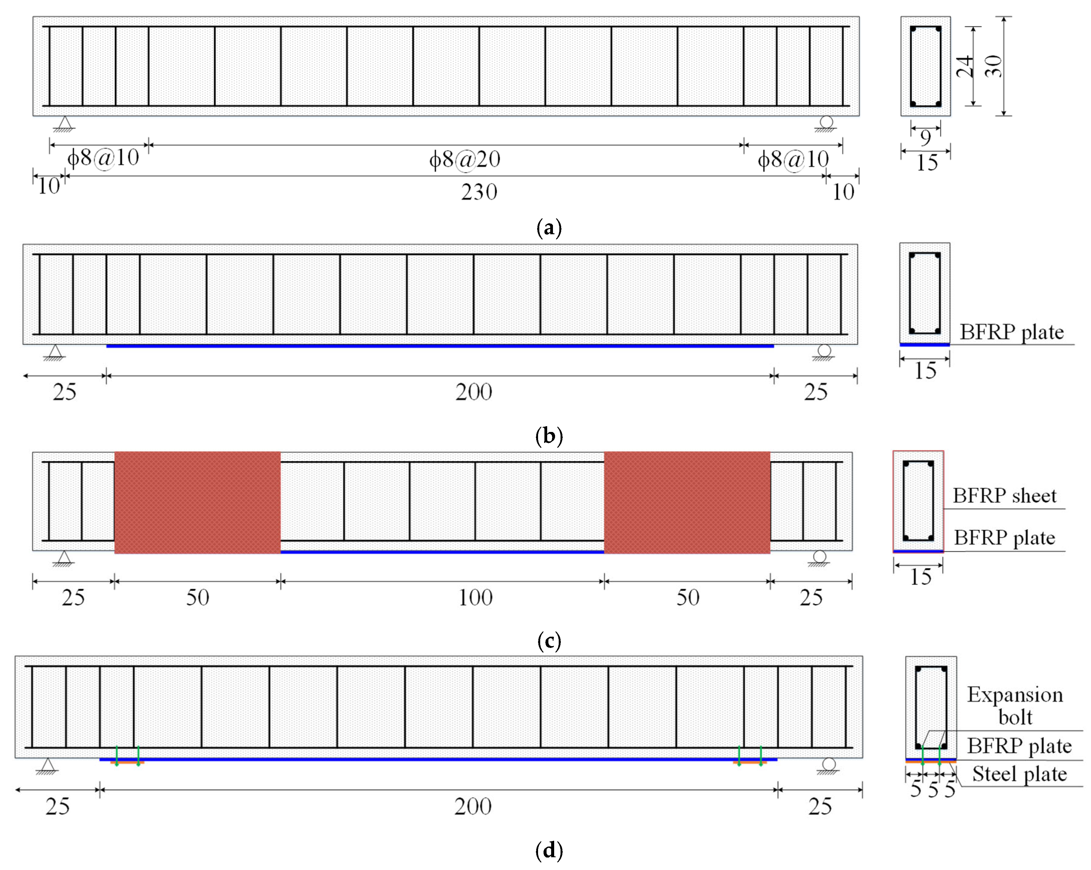
A total of 10 specimens were designed in the test. Each RC beam had an overall length of 2500 mm and a rectangular cross-section measuring 150 mm by 300 mm. The diameters of the longitudinal reinforcement and stirrups were 16 mm and 8 mm, respectively, with corresponding steel grades of HRB400 and HPB300. Two beams served as unstrengthened control specimens, while the remaining nine were strengthened specimens. All strengthened beams were externally bonded with novel BFRP plates fabricated with silicate-modified epoxy resin matrix, with a plate length of 2000 mm and a width of 150 mm. The thickness of the BFRP plate and the end anchorage configurations were changed to explore their influence on the flexural reinforcement performance. The design parameters are summarized in Table 1, in which the letters in the specimen names denote the end anchorage configurations, while the numbers indicate the thickness of the strengthened BFRP plates. The detailed geometric dimensions and strengthening layouts of the specimens are illustrated in Figure 1.
Prior to strengthening, the concrete soffit was ground to expose fresh concrete and repaired for irregularities. The epoxy adhesive was then prepared according to the specified mixing ratio and uniformly applied to the strengthened surface. During installation, the BFRP plates were pressed from the mid-span toward both ends to expel entrapped air within the epoxy adhesive. Subsequently, concrete blocks with equal weights were placed on the surface of the BFRP plates, and the specimens were allowed to cure naturally for a prescribed period until the adhesive hardened. For specimens with mechanical anchorage, end anchorage was provided using M8 expansion bolts and 6 mm thick steel plates, whereas for specimens with BFRP sheet wrap anchorage, the ends of the BFRP plates were wrapped with three layers of BFRP sheets.

2.2. Material Properties

The concrete used in the test was C50 grade. The compressive strength and elastic modulus of the concrete were determined by compressive strength tests. The novel BFRP plates, BFRP sheets and epoxy resin adhesive were sourced from a single integrated reinforcement system. The key material properties are summarized in Table 2.

2.3. Test Setup and Measuring Instrumentation

The test employed a four-point loading configuration, with the load applied to the specimens through a distribution beam. The constant moment region was 600 mm in length. Prior to formal loading, pre-loading was conducted to verify that all instruments were functioning properly, after which the formal test commenced. Load was applied in increments using force control before steel yielding and displacement control after yielding. When approaching failure, the displacement increment was reduced from 2 mm per step to 1 mm per step until specimen failure.
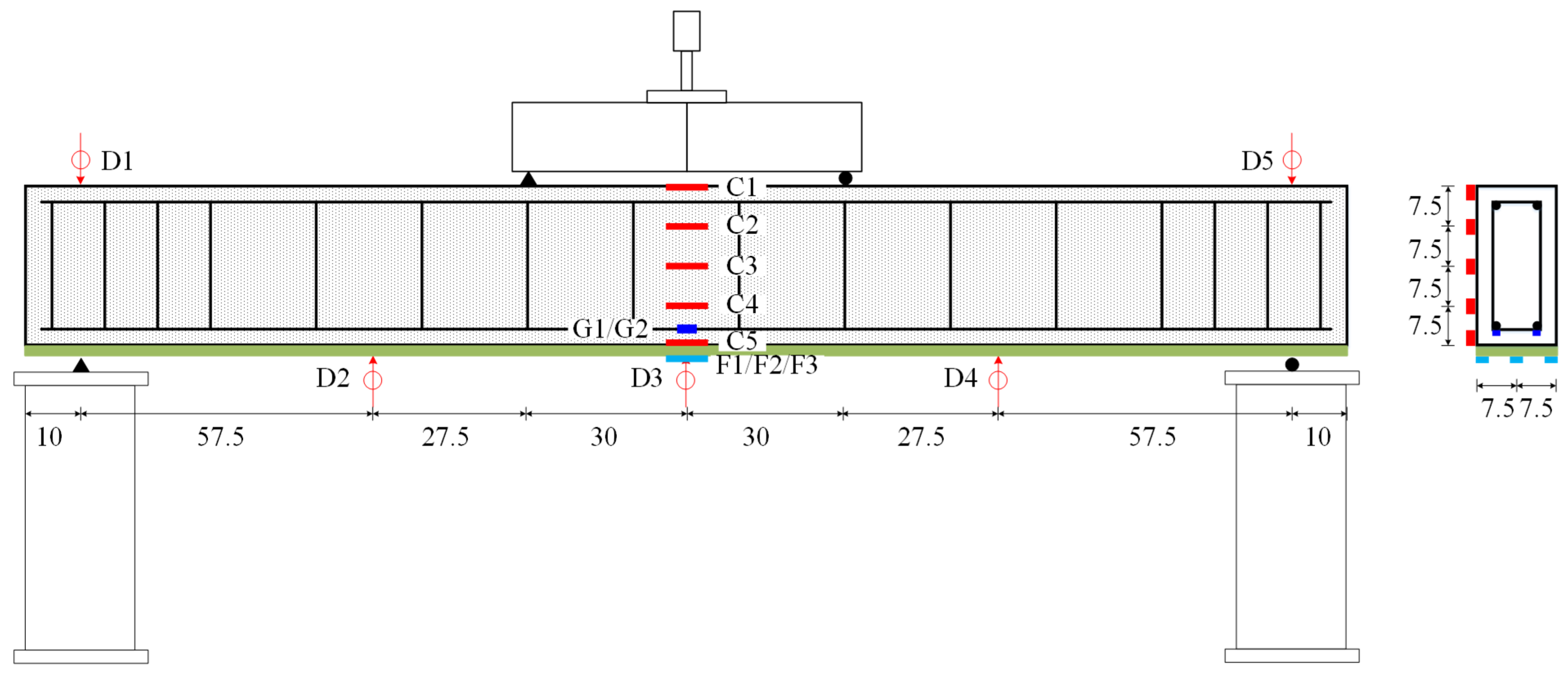
Linear Variable Differential Transformers, designated as D1–D5, were used to monitor the vertical deflection profile. To capture the sectional strain response, electrical resistance strain gauges were installed at the mid-span. Specifically, gauges G1–G2 were bonded to the longitudinal tensile reinforcement prior to casting. On the exterior, gauges C1–C5 were distributed along the beam depth to characterize the concrete strain profile, while gauges F1–F3 were evenly spaced across the width of the BFRP plate soffit, as illustrated in Figure 2. Additionally, a grid was marked on the lateral surface of the beam to facilitate the observation of crack initiation and propagation.

2.4. Test Results and Discussion

The final failure modes of all specimens are presented in Figure 3. During the test, three dominant failure modes were observed:
(1)
Concrete crushing in the compression zone. This mode occurred in the control specimens (CB1 and CB2) and the strengthened beams with mechanical anchorage (M-0.5 and M-1). The failure process exhibited the typical characteristics of under-reinforced RC beams: yielding of the longitudinal tensile reinforcement occurred first, followed by substantial flexural deformation. The ultimate failure was governed by the crushing of concrete in the compression zone. Notably, Specimen M-0.5 also exhibited longitudinal splitting of the BFRP plate, which initiated at the plate end and progressively propagated toward the mid-span along the fiber direction. This phenomenon was attributed to the relatively low BFRP plate thickness combined with the negligible transverse stiffness of the unidirectional plate. These factors led to stress concentrations in the mechanical anchorage region, ultimately triggering the longitudinal tearing of the plate.
(2)
Debonding failure of BFRP plates. This failure mode occurred in the strengthened beams without end anchorage (U-0.5, U-1, and U-2). Prior to debonding, no pronounced interfacial slip was observed along the FRP–concrete interface. The debonding initiated abruptly and propagated rapidly, exhibiting brittle failure characteristics. At the moment of debonding, a thin layer of concrete was attached to portions of the BFRP plate surface. Specimen U-0.5 also showed longitudinal splitting of the BFRP plate.
(3)
Shear compression failure. This mode was observed in strengthened beams with BFRP sheet circumferential wrapping (W-2, W-4, and W-6). Initially, flexural cracks appeared in the shear span; with increasing load, these extended toward the loading points, eventually evolving into a dominant diagonal crack. The ultimate failure was characterized by shear compression along a critical inclined section, accompanied by localized concrete crushing. Notably, crack propagation at the ultimate stage intensified stresses at the FRP–concrete interface within the anchorage region, inducing partial debonding. While the BFRP plates remained intact, the failure exhibited pronounced brittle characteristics.
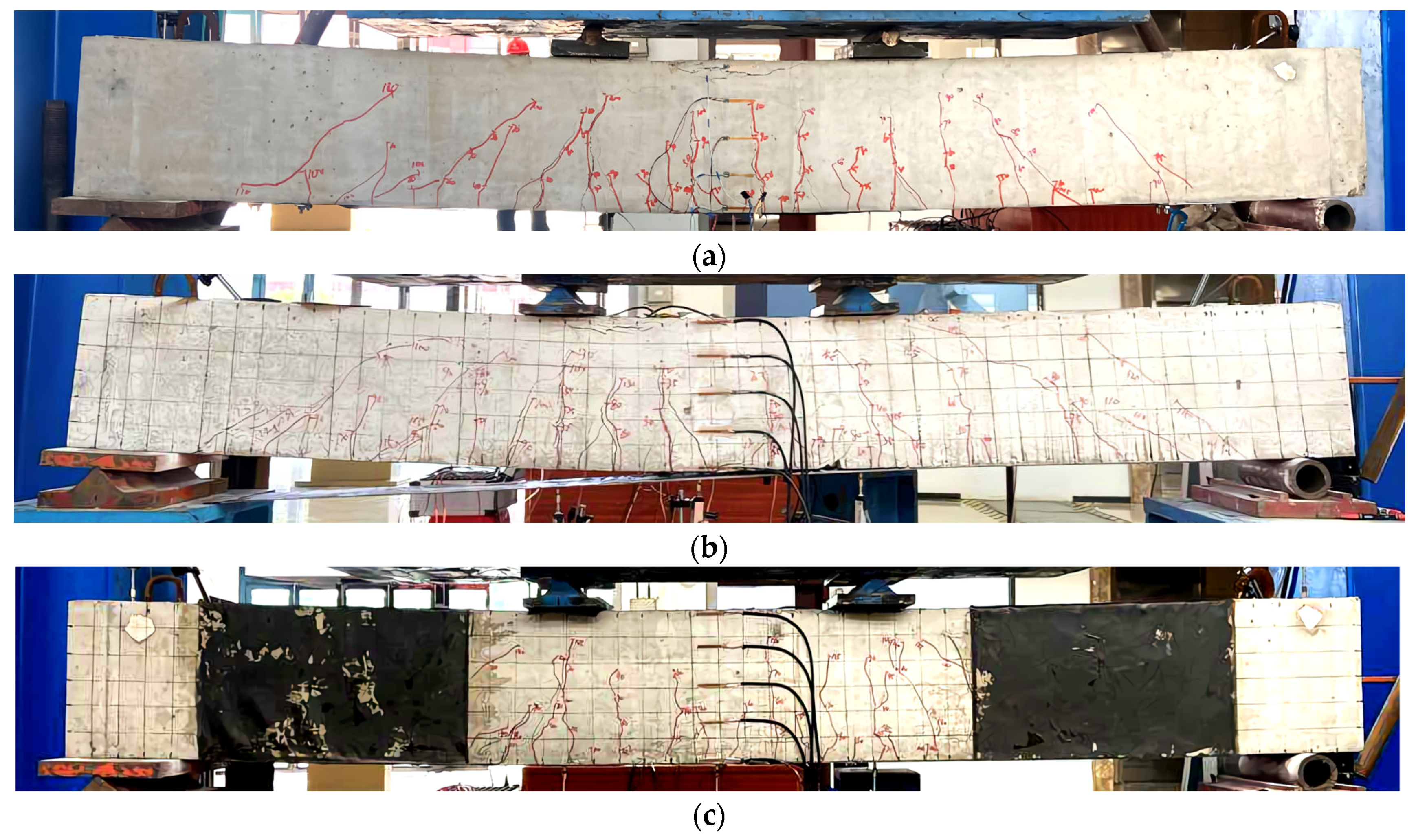
Figure 3. Failure modes of specimens: (a) compression failure; (b) debonding failure of BFRP plate; (c) shear compression failure.
Buildings 16 01031 g003
Overall, the strengthened beams without end anchorage exhibited abrupt interfacial debonding. The implementation of effective end anchorage significantly improved the structural response and shifted the failure mode. In specimens with BFRP sheet circumferential wrapping, the relatively large thickness of the BFRP plates combined with effective anchorage significantly enhanced the flexural capacity. However, this strengthening configuration had a limited effect on the shear capacity, leading to a ‘strong flexure and weak shear’ characteristic. Consequently, the strengthened specimens failed prematurely before reaching their theoretical flexural capacity, with the failure mode shifting to shear compression failure. For practical applications, the strengthening thickness of BFRP plates should not be excessively small, as insufficient thickness may induce localized longitudinal tearing at plate ends, reducing strengthening efficiency.
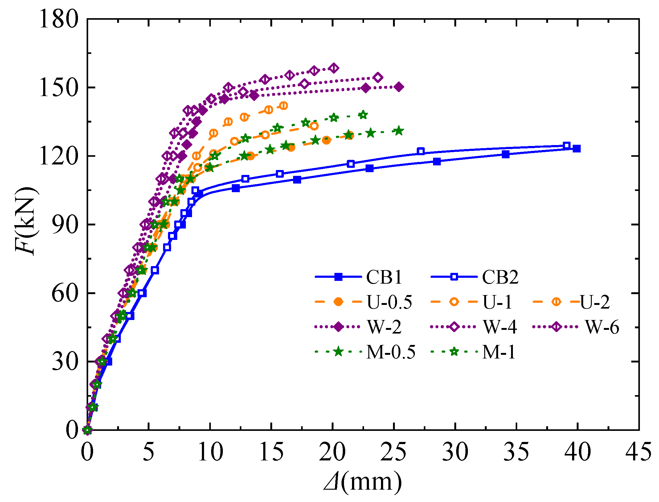
The characteristic loads and corresponding displacements of all specimens are summarized in Table 3, where Fcr, Fy and Fu denote the cracking load, yield load and ultimate load respectively. Δy and Δu represent the mid-span displacements measured at yield load and ultimate load respectively. The ductility coefficient is defined as μ = Δu/Δy. The load–displacement curves are shown in Figure 4.
Based on Table 3 and Figure 4, the following observations can be made:
(1)
The load–displacement curves of control beams CB1 and CB2 almost overlapped, indicating the high consistency and low dispersion of the test results.
(2)
During the initial loading stage, all specimens remained in the elastic regime, where the strain–lag effect of the BFRP plate limited its contribution. Consequently, the early-stage load–displacement responses of the strengthened and unstrengthened beams were nearly identical. Upon concrete cracking, the BFRP plate was progressively activated, leading to more effective internal-force redistribution and crack-propagation restraint. As a result, the strengthened beams showed a higher post-cracking flexural stiffness, Fy and Fu, and a marked reduction in Δu.
(3)
With the increase in BFRP plate thickness, the Fu of strengthened beams was enhanced, while μ was reduced. For unanchored strengthened beams, increasing the BFRP plate thickness from 0.5 mm to 2 mm linearly improved Fu (by 4.5% to 15.0%) but drastically reduced μ (by 42.9% to 64.9%). A similar tendency was observed in strengthened beams with mechanical anchorage. Strengthened beams using BFRP sheet circumferential wrapping anchorage were dominated by shear compression failure, so the increase in plate thickness had a limited influence on Fu.
(4)
Regarding the effect of end anchorage, the results indicate that, at the same BFRP plate thickness, applying end anchorage effectively delayed debonding damage and improved the Fu and μ. Notably, the mechanically anchored beams exhibited a μ increase of more than 20% relative to the unanchored beams, demonstrating a clear advantage in deformation capacity.
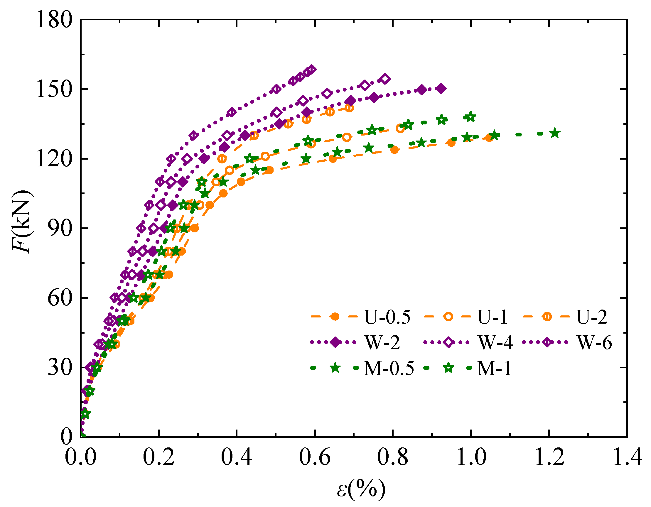
Figure 5 illustrates the load–strain curves of BFRP plates for the strengthened beams. The following observations can be made:
(1)
Prior to concrete cracking, the strains of BFRP plates increased nearly linearly with the loads. After cracking, the strain growth rates accelerated significantly.
(2)
Specimens with thicker BFRP plates exhibited lower strain levels under the same load, along with a reduced ultimate strain. This indicates a decrease in material utilization efficiency as thickness increases.
(3)
The strain curves of the BFRP plates largely coincided for beams with the same reinforcement thickness. However, specimens with end anchorage demonstrated delayed failure and correspondingly higher material utilization efficiency.
Figure 5. Load–strain curves of BFRP plates.
Buildings 16 01031 g005
In terms of failure mode and overall strengthening effectiveness, the novel BFRP plates exhibited similar behavior to existing FRP systems regarding the flexural strengthening of RC beams [38,39].

3. Finite Element Analysis

ABAQUS was employed to establish the FE model of RC beams strengthened with BFRP plates. For strengthened beams with end anchorage, flexural failure typically governs, and the effect of interface slip between FRP and concrete on structural behavior can be neglected. Accordingly, the FE analysis primarily focused on validating the experimental results for specimens that exhibited debonding failure and conducting a parameter analysis of the strengthening configuration.

3.1. Finite Element Modeling

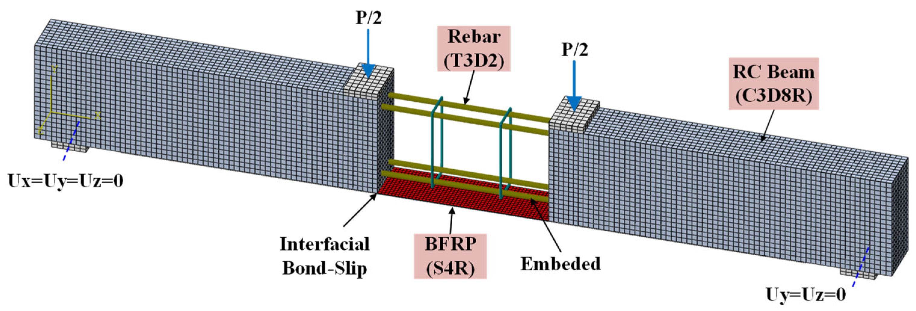
The FE model accounts for nonlinearities in material behavior, geometric response, and interfacial contact. The reinforcement was modeled with a bilinear constitutive relationship, and the concrete was described with the damaged plasticity model. All components were discretized with 3D solid elements (C3D8R), except for the steel reinforcement, which was represented by truss elements (T3D2). The established model is illustrated in Figure 6.
The bilinear model was used to simulate the stress–strain relationship of steel [40]. The concrete damaged plasticity (CDP) model provided by ABAQUS was employed to define the mechanical behavior of concrete. By incorporating the plasticity-damage formulation and the plasticity parameters, the failure behavior of concrete under complex stress states can be effectively described by the CDP model. The plasticity parameters in the CDP, including the dilation angle, eccentricity, stress ratio, shape factor, and viscosity factor, were taken to be 36◦, 0.1, 1.16, 0.6667, and 0.0005, respectively, after sensitive analyses. The constitutive relationships of concrete in tension and compression followed the equations adopted in the relevant code [41]. The mechanical indicators of materials in the models are consistent with the tested values.
In the FE model, a robust BFRP–concrete interface strategy was required to simulate the debonding failure. Existing numerical studies predominantly adopted either the cohesive surface-based contact method (CSCM) or the cohesive element method (CEM) to capture irreversible interface damage evolution. Although these two approaches differ in their numerical formulations, they are governed by the same interfacial traction–separation law and damage initiation criteria. Previous studies show negligible differences between CEM and CSCM regarding structural capacity and failure modes [42]. The CSCM offers not only satisfactory simulation accuracy but also superior computational efficiency and numerical stability [43]. Therefore, the CSCM was selected to represent the bond interaction between the BFRP plate and the RC beam.
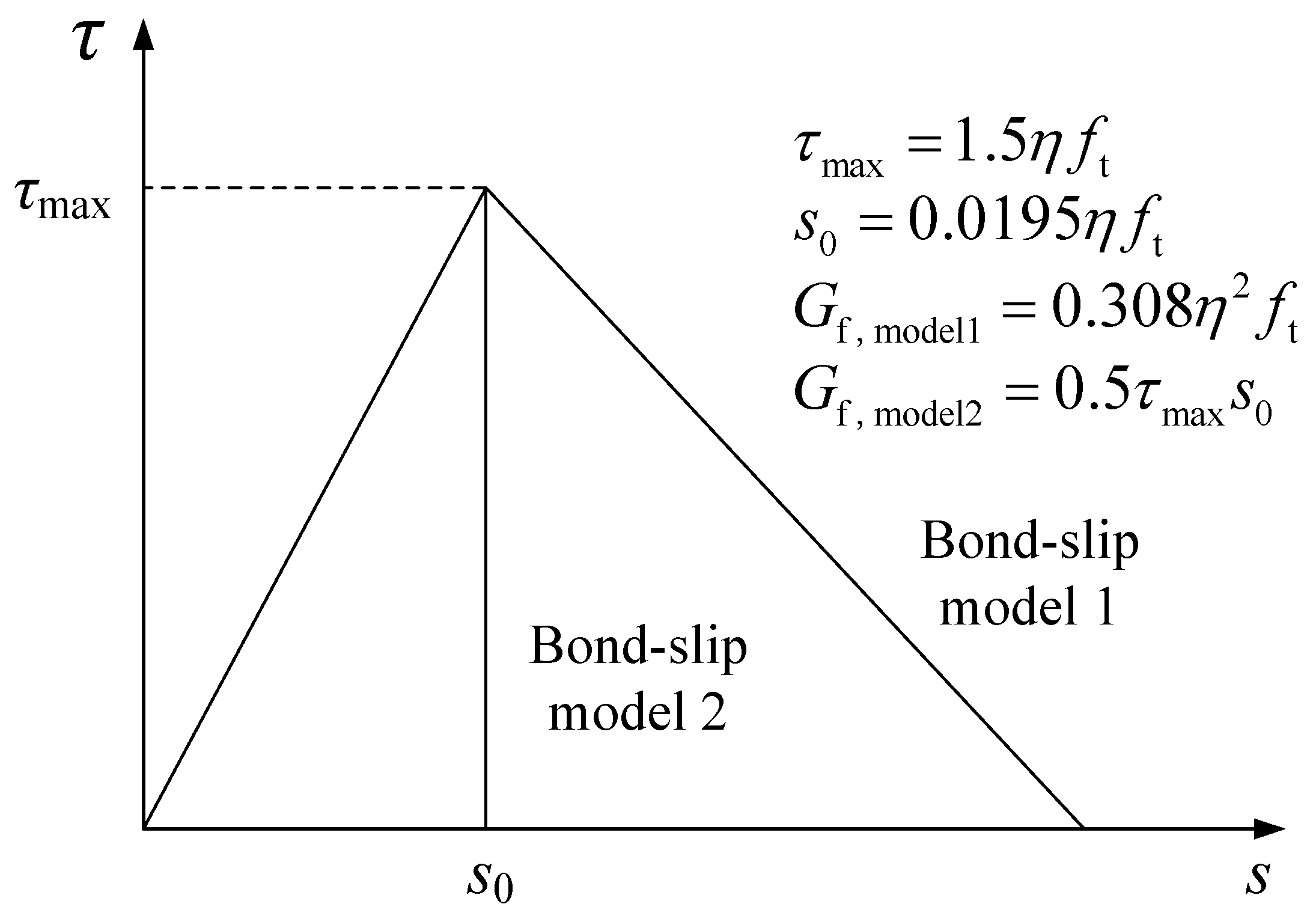
During the tests, no visible debonding process was observed at the end of the BFRP plate, and flexural cracks were primarily distributed within the constant moment region and adjacent areas. Accordingly, the FE model incorporated the FRP–concrete interface bond–slip constitutive relationship derived from the dual debonding criterion [44,45]. To improve computational convenience, a bilinear bond–slip model was adopted in Figure 7. For regions far from the constant moment region, bond–slip model 1 (governed by shear cracks) is adopted, while for the constant moment region and adjacent areas, bond–slip model 2 (governed by flexural cracks) is employed. In the model, the key parameters τmax, s0, Gf,model1 and Gf,model2 were set to 3.35 MPa, 0.044 mm, 0.074 kN/m and 0.296 kN/m, respectively.

3.2. Finite Element Verification

Based on the FE verification of the control RC beams, the strengthened beam simulation was performed, enabling the determination of the influence of the FRP–concrete interface bond–slip constitutive model on the numerical response of strengthened beams. The failure modes, load–displacement curves, and load–strain curves of the BFRP plates for specimens U-0.5, U-1, and U-2 were obtained from the FE analysis and subsequently compared with the experimental results so as to validate the FE modeling strategy.
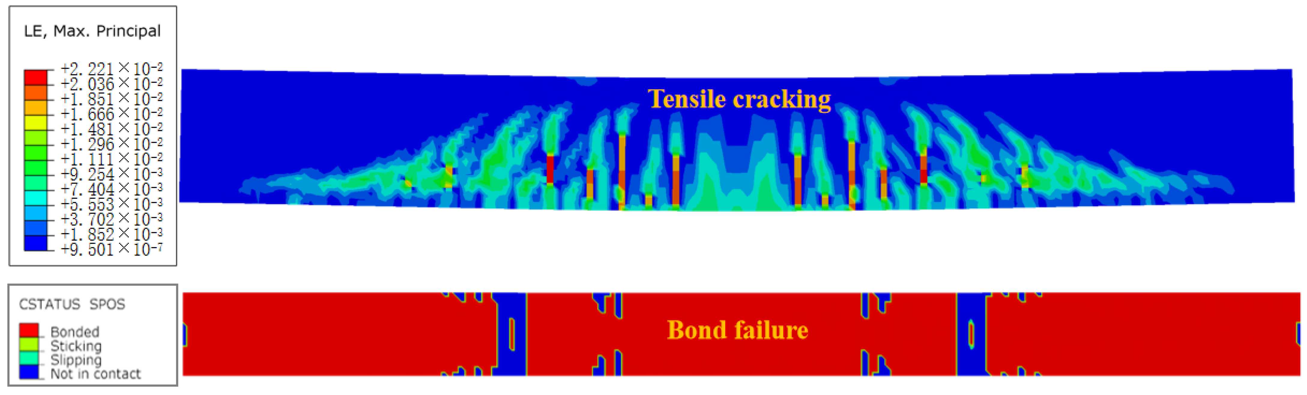
Figure 8 illustrates the failure mode of the strengthened beams derived from the FE analysis. Pronounced tensile cracks appeared near the constant moment region of the concrete beam. The final failure of the specimens occurred as interfacial debonding between the BFRP plate and the concrete near the loading point section, which determined the ultimate bearing capacity. In the FE model, the interfacial slip also occurred primarily near the ultimate state. Due to the brittle nature of this failure process, complete separation of the BFRP plate was not observed in the simulation, which was consistent with the experimental observations.
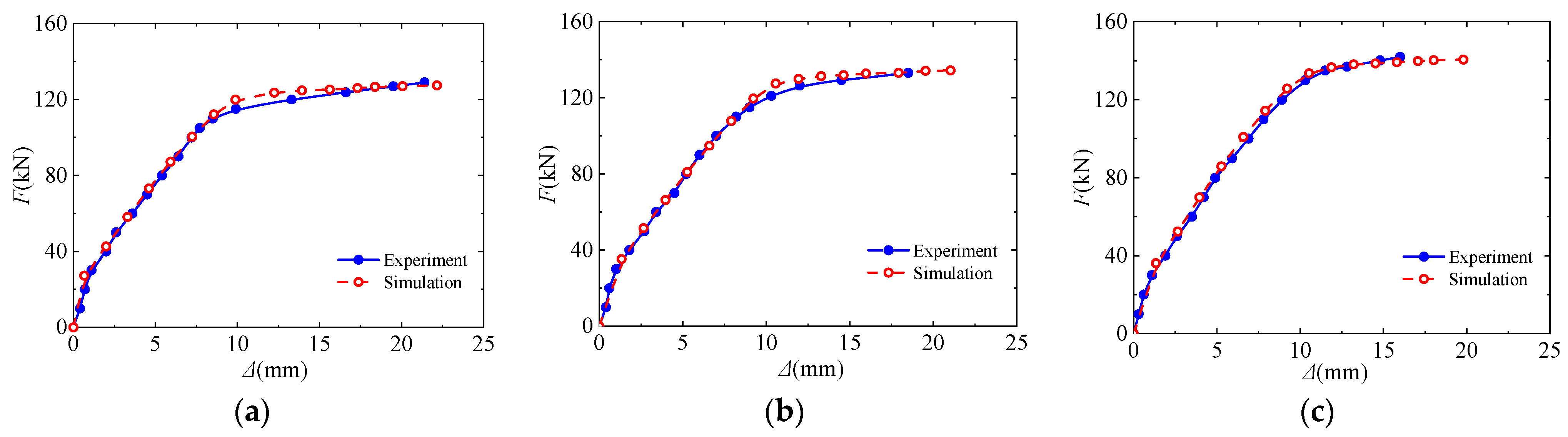
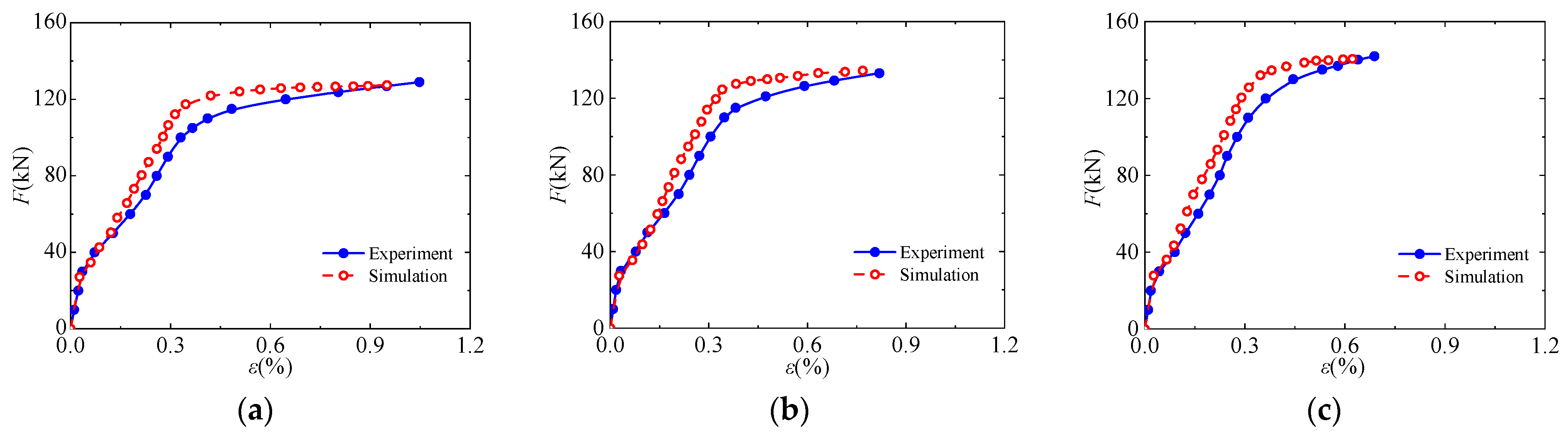
The load–displacement curves and load–strain curves for the BFRP plates, derived from FE analysis, are compared with the experimental results in Figure 9 and Figure 10. The simulations for all specimens showed excellent agreement with the experimental data. In the elastic stage, the stiffness exhibited negligible differences. As the specimens entered the yield stage, increasing the thickness of the BFRP plate resulted in a higher ultimate bearing capacity but reduced the utilization efficiency of the BFRP plate. These trends were consistent with the experimental results.
The values for Fy, Fu and the BFRP plate strain at failure (εf) were extracted and compared with the experimental results, as listed in Table 4. The FE analysis predicted these values with minimal deviation from the experimental data. Notably, the relative error of εf remained within 10%.
Overall, the failure mode, load–displacement curves, and load–strain curves of the BFRP plates obtained from the FE simulations were in good agreement with the experimental results, indicating that the bond–slip constitutive model adopted in the FE analysis provided a reasonable and accurate representation of the concrete–FRP interface behavior in the flexurally strengthened RC beams.

3.3. Parametric Analysis

Due to the limited number of test specimens, the effects of different design parameters on the flexural strengthening of RC beams without end anchorage could not be investigated experimentally in detail. Key factors affecting the bond performance between FRP and concrete include concrete strength, FRP elastic modulus and thickness. Consequently, a parametric analysis based on the control group was conducted to evaluate the influence of these variables on the flexural strengthening effect. Considering that the elastic modulus of the novel BFRP plates is lower than that of conventional versions (typically ranging from 50 to 80 GPa), a modulus range below 50 GPa was adopted for the parameter analysis. The parameter scheme is summarized in Table 5, which also presents the calculated FuF and εfF values for each specimen.

3.3.1. BFRP Plate Thickness

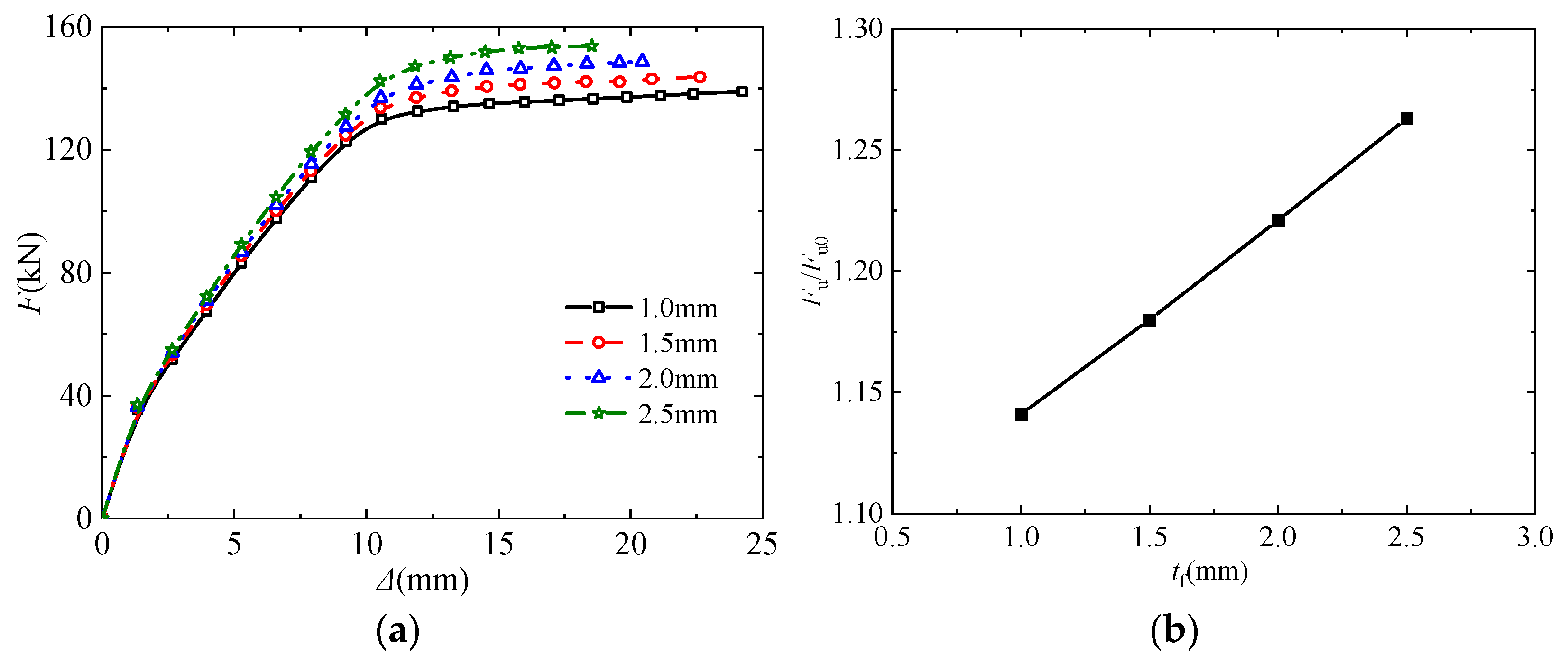
The impact of BFRP plate thickness on flexural performance is depicted in Figure 11. For relatively thin plates, the flexural capacity of the specimen increased only marginally, and the ultimate load was reached shortly after yielding. This indicates a limited strengthening effect, characterized by the concurrent occurrence of concrete crushing and interfacial debonding. As the BFRP plate thickness increased, the ultimate bearing capacity rose significantly, albeit accompanied by a gradual decrease in failure displacement. This confirms that increasing the plate thickness effectively enhances the ultimate load. As summarized in Figure 11b, where Fu0 denotes the ultimate load of the unstrengthened beam, the improvement in ultimate load exhibited an approximately linear relationship with thickness within the studied range, which aligns well with the test results.

3.3.2. Concrete Grades

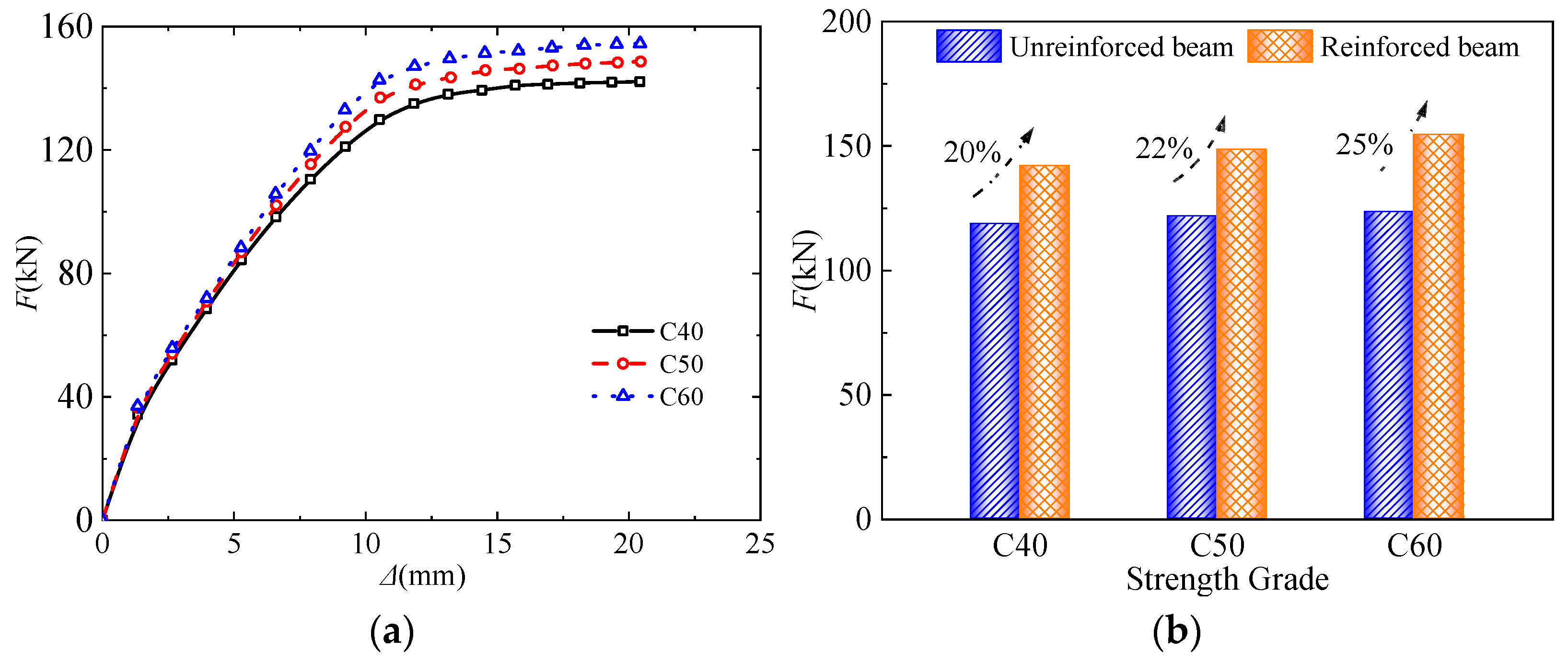
Figure 12 presents the effect of concrete strength on flexural performance. It is evident that as the concrete strength increased, both the flexural stiffness and the flexural capacity improved. As quantified in Figure 12b, the flexural capacities of C40, C50, and C60 strengthened beams increased by 20%, 22%, and 25%, respectively, compared to the unstrengthened beams. This enhancement suggests that higher concrete strength improved the bond strength at the FRP–concrete interface, thereby contributing to a slight increase in the ultimate load of the strengthened specimens.

3.3.3. Elastic Modulus of BFRP Plate

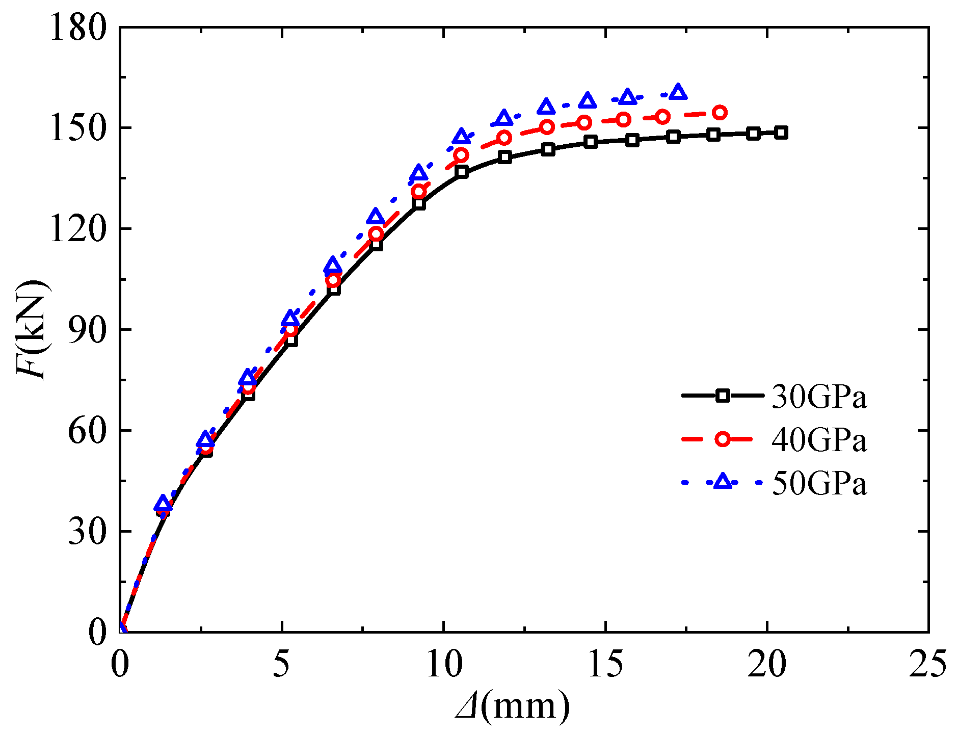
Figure 13 presents the load–displacement curves of strengthened beams with varying elastic moduli. It is evident that increasing the elastic modulus of the BFRP plates enhanced the flexural stiffness, yield load and flexural capacity of the beams, while the failure displacement decreased progressively. Specifically, when the elastic modulus increased from 30 GPa to 50 GPa, the flexural capacity rose by 7.7%, while the failure displacement decreased by 15.6%.

4. Analysis of Flexural Capacity of Strengthened Beams

Since strengthened beams with end anchorage predominantly exhibit flexural failure, their flexural capacity is largely independent of the concrete–FRP interfacial bond. Consequently, calculation methods for such flexural failures are well-established and widely adopted in FRP design guidelines. However, strengthened beams that fail due to debonding do not fully utilize the tensile strength of FRP, and research on calculation methods in predicting their capacity remains limited. Moreover, most existing research focused on high-modulus CFRP materials. The novel BFRP plate adopted in this study, characterized by a low elastic modulus and high ductility, differs significantly from CFRP. Therefore, this section focuses on developing a calculation method for the flexural capacity of RC beams strengthened with this specific BFRP material.

4.1. BFRP Plate Strain at Debonding Failure

In FRP-strengthened RC beams, debonding at the end of the FRP plate is typically caused by a stress concentration arising from the stiffness discontinuity. However, due to the relatively low stiffness of the BFRP plates used in this study, this specific failure mode is less likely to occur. In contrast, IC debonding is the predominant failure mechanism for BFRP flexural strengthening. Within the constant moment region, wide flexural cracks induce significant local bond stress concentrations at the crack roots. Consequently, considerable slip occurs between the FRP and concrete at these locations, triggering debonding prior to material rupture. References [30,46] combined the FRP–concrete interface bond strength model with a simple section analysis to propose an equation for predicting FRP strain at IC debonding. A modified version of this equation, adopted by the specification in [7], is presented as Equation (1).
ε fd = 0.41 f c n E f t f
where εfd represents the strain of the FRP plate, fc’ denotes the compressive strength of the concrete cylinder, and nEftf signifies the stiffness of the FRP plate.
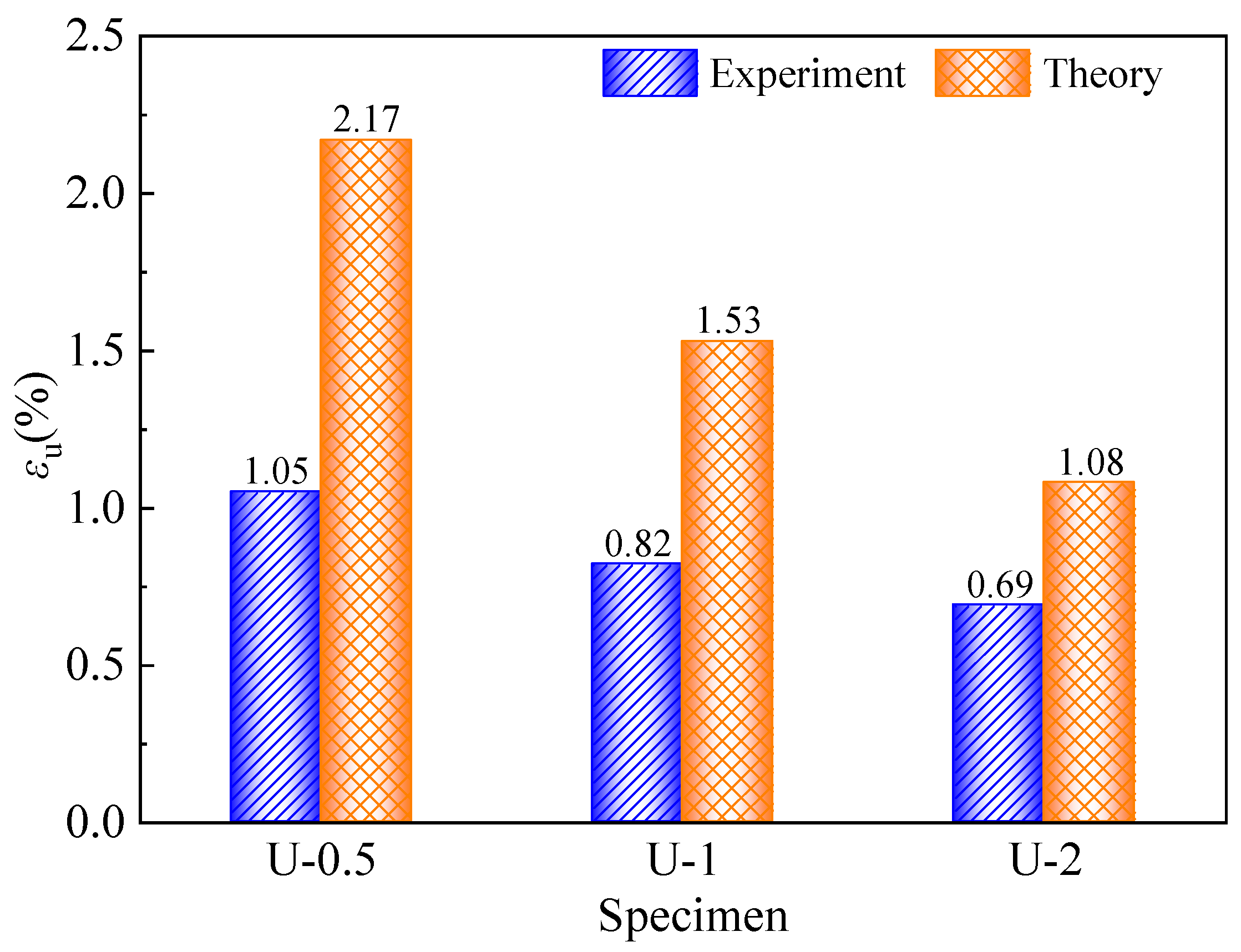
The design parameters of the specimens were substituted into Equation (1) to calculate the debonding strains, which were then compared with the experimental values (Figure 14). The comparison reveals a significant discrepancy between the theoretical and experimental values. Specifically, the calculated strains are much higher than the experimental results. Consequently, applying this formula to the BFRP-strengthened beams in this study would result in an overestimation of their ultimate bearing capacity.
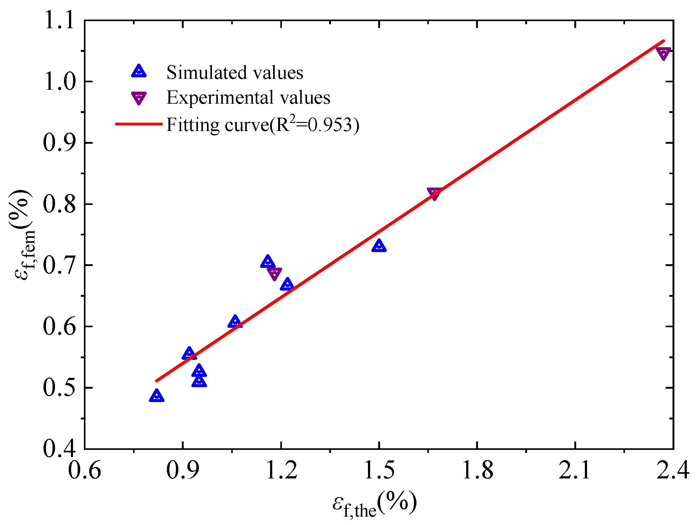
The existing model relies on a bond strength formulation derived primarily from debonding tests conducted on CFRP composites. Since these materials are typically characterized by a high elastic modulus and low ultimate strain, the model is inherently tailored to such properties. In contrast, BFRP exhibits a low elastic modulus and considerably high ultimate strain. Moreover, the interfacial debonding failure of strengthened beams is governed not only by the interface constitutive behavior but also by the flexural crack characteristics of the concrete. Consequently, directly applying the existing equation to BFRP-strengthened beams introduces substantial errors. To address this, the existing equation was recalibrated via linear regression. Using the εfd values obtained from the experimental and FE parametric analyses (covering varying concrete strengths, elastic moduli, and thicknesses, as listed in Table 4 and Table 5), Equation (2) was established.
ε fd = m 0.41 f cm E f t + n
The complete dataset was fitted to generate the curve presented in Figure 15. Based on this regression, a modified predictive equation for the BFRP debonding strain was derived, as given in Equation (3). The coefficient of determination (R2 = 0.953) indicates a strong correlation between the proposed model and the data, demonstrating excellent agreement. Within the calibrated parameter range, the modified equation provides reliable predictions, confirming its applicability for theoretical calculations and performance analysis of debonding-governed flexural capacity.
ε fd = 0.147 f cm E f t + 0.0022

4.2. Calculation of Flexural Bearing Capacity at Debonding Failure

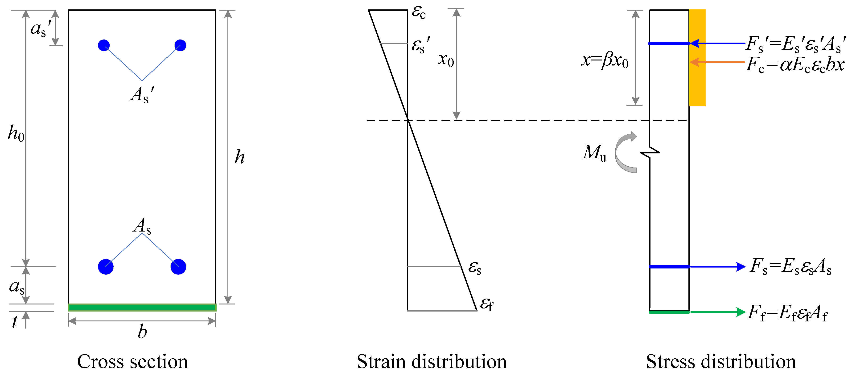
The strengthened RC beams exhibited a failure mode governed by the premature debonding of the EB BFRP plate. At the onset of failure, the BFRP plate strain reached the debonding limit, εf. The corresponding sectional analysis schematic is illustrated in Figure 16. Given that the thickness of the adhesive layer is negligible compared to the beam depth, its contribution on the sectional geometric is neglected. Based on the assumptions of strain compatibility, the strain distribution in the concrete and internal reinforcement is expressed as in Equations (4)–(6).
ε c = x 0 h x 0 + 0.5 t ε f ε cu
ε s = h 0 x 0 h x 0 + 0.5 t ε f ε y
ε s = x 0 a s h x 0 + 0.5 t ε f ε y
where εc, εs and εs’ represent the concrete compressive strain, tensile reinforcement strain and compressive reinforcement strain, respectively. x0 denotes the actual neutral axis depth, while x represents the depth of the equivalent rectangular stress block, defined by the coefficient β0. h0 and h refer to the total section depth and the effective depth, respectively. as and as’ denote the distance from the centroids of the tensile and compressive reinforcement to the nearest section edges. Finally, εcu and εy correspond to the ultimate compressive strain of concrete and the yield strain of reinforcement, respectively.
Based on the geometry in Figure 15, Equations (8) and (9) are established.
E f ε f A f + E s ε s A s = α E c ε c b x + E s ε s A s
M u = E f ε f A f ( h x 2 + t 2 ) + E s ε s A s ( h 0 x 2 ) + E s ε s A s ( x 2 a s )
where Es, Es’ and Ec denote the elastic moduli of longitudinal tensile reinforcement, longitudinal compressive reinforcement and concrete respectively. Af, As and As’ represent the cross-sectional area of the BFRP plate, longitudinal tensile reinforcement and longitudinal compression reinforcement, respectively. α is the coefficient of equivalent rectangular stress distribution in the concrete compression zone, determined in accordance with code [41].
Based on the given reinforcement design parameters, the specific procedure for calculating the flexural capacity of RC beams strengthened with the novel BFRP plates can be determined through a systematic four-step procedure. First, parameter εf is calculated using Equation (3). Subsequently, the key variables εc, εs, and εs’ at the onset of debonding failure are determined via Equations (4)–(6). In the third step, the neutral axis depth (x) is solved by substituting the obtained parameters into Equation (7). Finally, the ultimate moment capacity (Mu) is predicted using Equation (8).
Following the calculation procedure, the ultimate flexural capacity (Mu) of BFRP-strengthened RC beams was calculated and compared with the FE simulation results. A summary of this comparison is presented in Table 6.
Table 6 demonstrates that the proposed analytical model incorporating the modified BFRP strain formula yields highly accurate predictions. The calculated flexural capacities exhibit excellent agreement with both the finite element simulations and experimental data, with deviations generally within 5%. This validates the reliability of the theoretical formula for guiding the flexural strengthening design of RC beams using BFRP plates.

5. Conclusions

In this paper, the influence of the thickness and anchorage form of the novel BFRP plate on the flexural strengthening behavior of RC beams was investigated through four-point bending tests. Incorporating the interfacial bond–slip behavior, an FE model of BFRP-strengthened beams was developed. Subsequently, the impact of various factors on flexural capacity was comprehensively analyzed, and a theoretical model for predicting flexural capacity under debonding failure was derived. The main conclusions are summarized as follows:
(1)
For unanchored strengthened beams, which consistently failed due to debonding, increasing the plate thickness from 0.5 mm to 2 mm raised the flexural capacity gain from 4.5% to 15% but intensified the ductility reduction from 42.9% to 64.9%. Effective end anchorage prevented brittle failure, further enhancing both flexural capacity and ductility. The novel BFRP plate exhibited flexural strengthening behavior similar to that of existing FRP systems.
(2)
The adopted bond–slip constitutive model accurately captured the debonding failure behavior of RC beams strengthened with the novel BFRP plates, with FE simulation results showing excellent agreement with test data, providing a robust analytical foundation for the refined numerical simulation and performance evaluation of such strengthening systems.
(3)
The ACI 440.2R-17 specification was found to produce certain discrepancies in predicting the debonding strain of the novel BFRP plates in strengthened beams. To address this, a modified predictive formula for the BFRP plates’ debonding strain was proposed based on regression analysis, which provides a robust framework that more accurately captures the onset and characteristics of debonding failure for the novel BFRP system.
(4)
The flexural capacity calculation method of the novel BFRP-strengthened beams under debonding failure was proposed based on the modified strain formula. The theoretical predictions exhibit a high degree of accuracy with deviations within 5%, demonstrating that the proposed method provides a reliable basis for the design of RC beams strengthened with the novel BFRP plates.

Author Contributions

Conceptualization, X.Y. and H.S.; methodology, X.Y.; software, Z.L.; validation, Z.L., and X.Y.; formal analysis, X.Y.; investigation, Z.L.; resources, H.Z.; data curation, H.S.; writing—original draft preparation, Z.L. and X.Y.; writing—review and editing, Z.L. and X.Y.; visualization, H.S. and H.Z.; supervision, H.S.; project administration, H.Z.; funding acquisition, H.Z. All authors have read and agreed to the published version of the manuscript.

Funding

This research received no external funding.

Data Availability Statement

The original contributions presented in this study are included in the article. Further inquiries can be directed to the corresponding author.

Conflicts of Interest

Author Xingzhan Ye was employed by the company Yuexiu (China) Transport Infrastructure Investment Company Limited. Authors Zheng Li, Huijun Shen and Hehui Zheng were employed by the company CCCC Second Harbour Engineering Co., Ltd. Authors Zheng Li and Huijun Shen were employed by the company Key Laboratory of Large-Span Bridge Construction Technology, Ltd. Author Hehui Zheng was employed by the company CCCC Highway Bridge National Engineering Research Centre Co. Ltd. The remaining authors declare that the research was conducted in the absence of any commercial or financial relationships that could be construed as potential conflicts of interest.

References

  1. Sbahieh, S.; Rabie, M.; Ebead, U.; Al-Ghamdi, S.G. The mechanical and environmental performance of fiber-reinforced polymers in concrete structures: Opportunities, challenges and future directions. Buildings 2022, 12, 1417. [Google Scholar] [CrossRef] [Scilit]
  2. Zheng, S.; Hu, T.; Yu, Y. Interpretable Machine Learning-Based Prediction Model for Concrete Cover Separation of FRP-Strengthened RC Beams. Materials 2024, 17, 1957. [Google Scholar] [CrossRef] [Scilit]
  3. Al Nuaimi, N.; Sohail, M.G.; Hawileh, R.; Abdalla, J.A.; Douier, K. Durability of reinforced concrete beams externally strengthened with CFRP laminates under harsh climatic conditions. J. Compos. Constr. 2021, 25, 04021005. [Google Scholar] [CrossRef] [Scilit]
  4. Slaitas, J.; Valivonis, J. Full moment-deflection response and bond stiffness reduction of RC elements strengthened with prestressed FRP materials. Compos. Struct. 2021, 260, 113265. [Google Scholar] [CrossRef] [Scilit]
  5. Slaitas, J.; Valivonis, J. Concrete cracking and deflection analysis of RC beams strengthened with prestressed FRP reinforcements under external load action. Compos. Struct. 2021, 255, 113036. [Google Scholar] [CrossRef] [Scilit]
  6. GB 50608-2010; Technical Code for Infrastructure Application of FRP Composites. Ministry of Housing and Urban-Rural Development of the People’s Republic of China: Beijing, China, 2010.
  7. ACI 440.2R-17; Guide for the Design and Construction of Externally Bonded FRP Systems for Strengthening Concrete Structures. ACI Committee 440; American Concrete Institute: Farmington Hills, MI, USA, 2017.
  8. CAN/CSA S806-12; Design and Construction of Building Components with Fibre-Reinforced Polymers. Canadian Standards Association (CSA): Mississauga, ON, Canada, 2012.
  9. CNR-DT 200 R1/2013; Guide for the Design and Construction of Externally Bonded FRP Systems for Strengthening Existing Structures. National Research Council: Rome, Italy, 2013.
  10. Salameh, A.; Hawileh, R.; Safieh, H.; Assad, M.; Abdalla, J. Elevated Temperature Effects on FRP–Concrete Bond Behavior: A Comprehensive Review and Machine Learning-Based Bond Strength Prediction. Infrastructures 2024, 9, 183. [Google Scholar] [CrossRef] [Scilit]
  11. Gong, S.; Su, M.; Deng, X.; Song, Z.; Yoshitake, I.; Peng, H. Temperature effects on bonding performance of near-surface-mounted CFRP concrete interfaces: Experimental and finite element studies. Eng. Struct. 2026, 354, 122395. [Google Scholar] [CrossRef] [Scilit]
  12. Wang, Y.X.; Ye, N.L.; Liu, S.Q.; Zhang, Z.Q.; Hu, Y.F.; Wei, A.B.; Wang, H.T. Bond Strength Evaluation of FRP–Concrete Interfaces Affected by Hygrothermal and Salt Attack Using Improved Meta-Learning Neural Network. Appl. Sci. 2024, 14, 5474. [Google Scholar] [CrossRef] [Scilit]
  13. He, W.L.; Jiang, X.Y.; He, R.Q.; Zheng, Y.T.; Dai, D.X.; Huang, L.F.; Yao, X.M. A Review on the Aging Behavior of BADGE-Based Epoxy Resin. Buildings 2025, 15, 2450. [Google Scholar] [CrossRef] [Scilit]
  14. Smoleń, J.; Olesik, P.; Nowacki, B.; Godzierz, M.; Kurtyka, K.; Chaber, P.; Czakiert, J.; Kozioł, M. The influence of UV radiation on the properties of GFRP laminates in underwater conditions. Sci. Rep. 2024, 14, 7446. [Google Scholar] [CrossRef] [Scilit]
  15. Lohani, S.; Shubham; Prusty, R.K.; Ray, B.C. Effect of ultraviolet radiations on interlaminar shear strength and thermal properties of glass fiber/epoxy composites. Mater. Today Proc. 2021, 43, 524–529. [Google Scholar] [CrossRef] [Scilit]
  16. Harle, S.M. Durability and long-term performance of fiber reinforced polymer (FRP) composites: A review. Structures 2024, 65, 105881. [Google Scholar] [CrossRef] [Scilit]
  17. Xian, G.; Guo, R.; Li, C.; Wang, Y. Mechanical performance evolution and life prediction of prestressed CFRP plate exposed to hygrothermal and freeze-thaw environments. Compos. Struct. 2022, 293, 115719. [Google Scholar] [CrossRef] [Scilit]
  18. Wang, Y.Q.; Zeng, Z.; Huang, Z.Y.; Shang, J. Preparation and characteristics of silicone-modified aging-resistant epoxy resin insulation material. J. Mater. Sci. 2022, 57, 3295–3308. [Google Scholar] [CrossRef] [Scilit]
  19. Anwar, S.; Li, X. A review of high-quality epoxy resins for corrosion-resistant applications. J. Coat. Technol. Res. 2024, 21, 461–480. [Google Scholar] [CrossRef] [Scilit]
  20. Chen, L.S.; Shen, H.J.; Zheng, H.H.; Zhang, L. Experimental-numerical study on axial compression performance of square concrete columns confined by new-type BFRP. Phys. Scr. 2024, 99, 065042. [Google Scholar] [CrossRef] [Scilit]
  21. Li, W.; Chen, Y.; Pham, T.M.; Hao, H. Effect of elevated temperature on the mechanical properties of basalt fiber reinforced polymer (BFRP) plates. Constr. Build. Mater. 2021, 285, 122863. [Google Scholar]
  22. Kuntal, V.S.; Chellapandian, M.; Suriya Prakash, S.; Sharma, A. Experimental study on the flexural behavior of RC beams strengthened with prestressed BFRP laminates. Eng. Struct. 2021, 242, 112521. [Google Scholar]
  23. Manibalan, P.; Kesaven, S.; Abirami, G.; Baskar, R. Fatigue response of RC beam strengthened by BFRP laminate. Case Stud. Constr. Mater. 2023, 18, e01707. [Google Scholar] [CrossRef] [Scilit]
  24. Chen, W.S.; Pham, T.M.; Sichembe, H.; Chen, L.; Hao, H. Experimental study of flexural behaviour of RC beams strengthened by longitudinal and U-shaped basalt FRP sheet. Compos. Part B Eng. 2018, 134, 114–126. [Google Scholar] [CrossRef] [Scilit]
  25. Gao, Z.; Pan, D.; Qin, Q.; Zhang, C.; He, J.; Lin, Q. Experimental Study on Mechanical Performance of Basalt Fiber-Reinforced Polymer Plates with Different Bolted Connection Configurations. Polymers 2025, 17, 2627. [Google Scholar] [CrossRef] [Scilit]
  26. Shen, H.; Chen, L.; Zheng, H.; Zhang, F. Experimental study on axial compression performance of new-type BFRP-confined square concrete columns. J. Compos. Mater. Sci. Eng. 2023, 9, 106–111. [Google Scholar] [CrossRef] [Scilit]
  27. Liu, C.Y.; Wang, X.; Chang, X.Q.; Wu, Z.; Zhu, Z.; Wang, H.; Bian, Z. Experimental study on wedge anchorage performance of prestressed BFRP laminates for flexural strengthening of reinforced concrete components. J. Compos. Constr. 2023, 27, 04023043. [Google Scholar] [CrossRef] [Scilit]
  28. Effiong, J.U.; Ede, A.N. Experimental investigation on the strengthening of reinforced concrete beams using externally bonded and near-surface mounted natural fibre reinforced polymer composites—A review. Materials 2022, 15, 5848. [Google Scholar] [CrossRef] [Scilit]
  29. Smith, S.T.; Teng, J.G. FRP-strengthened RC beams. I: Review of debonding strength models. Eng. Struct. 2002, 24, 385–395. [Google Scholar] [CrossRef] [Scilit]
  30. Teng, J.G.; Smith, S.T.; Yao, J.; Chen, J.F. Intermediate crack-induced debonding in RC beams and slabs. Constr. Build. Mater. 2003, 17, 447–462. [Google Scholar] [CrossRef] [Scilit]
  31. Kalfat, R.; Al-Mahaidi, R.; Smith, S.T. Anchorage devices used to improve the performance of reinforced concrete beams retrofitted with FRP composites: State-of-the-art review. J. Compos. Constr. 2013, 17, 14–33. [Google Scholar] [CrossRef] [Scilit]
  32. Hawileh, R.A.; Assad, M.; Abdalla, J.A. Effect of Increasing the Number of Anchors on the Flexural Performance of FRP-Strengthened RC Beams. Procedia Struct. Integr. 2024, 54, 287–293. [Google Scholar] [CrossRef] [Scilit]
  33. Ren, Y.; Wang, H.; Guan, Z.; Yang, K. Evaluation of the Properties and Applications of FRP Bars and Anchors: A Review. Rev. Adv. Mater. Sci. 2023, 62, 20220287. [Google Scholar] [CrossRef] [Scilit]
  34. Monti, M.; Renzelli, M.; Luciani, P. FRP adhesion in uncracked and cracked concrete zones. In Proceedings of the 6th International Symposium on FRP Reinforcement for Concrete Structures, Singapore, 8–10 July 2003. [Google Scholar]
  35. Dai, J.G.; Ueda, T.; Sato, Y. Development of the nonlinear bond stress-slip model of fiber reinforced plastics sheet-concrete interfaces with a simple method. J. Compos. Constr. 2005, 9, 52–62. [Google Scholar] [CrossRef] [Scilit]
  36. Fathi, A.; El-Saikaly, G.; Chaallal, O. Experimental and Analytical Study of Bond Stress–Slip Behavior at the CFRP-to-Concrete Interface. J. Compos. Constr. 2023, 27, 04023009. [Google Scholar] [CrossRef] [Scilit]
  37. Aghabagloo, M.; Carreras, L.; Barahona, M.; Ribas, C.; Baena, M.; Torres, L. Experimental Study and Numerical Prediction of the Bond-Slip Law for Concrete Elements Strengthened with FRP Using Metaheuristic Algorithm. Constr. Build. Mater. 2024, 411, 134712. [Google Scholar] [CrossRef] [Scilit]
  38. Ceroni, F. Experimental performances of RC beams strengthened with FRP materials. Constr. Build. Mater. 2010, 24, 1547–1559. [Google Scholar] [CrossRef] [Scilit]
  39. Mostofinejad, D.; Hosseini, S.M.; Nader Tehrani, B.; Eftekhar, M.R. Innovative warp and woof strap (WWS) method to anchor the FRP sheets in strengthened concrete beams. Constr. Build. Mater. 2019, 218, 351–364. [Google Scholar] [CrossRef] [Scilit]
  40. Nguyen, N.T.; Nguyen, T.K.; Du, D.H.; Nguyen, D.N.; Kieu, T.S. Nonlinear Finite Element Analysis of FRP-Strengthened Full-Size Reinforced Concrete Beams. Innov. Infrastruct. Solut. 2023, 8, 139. [Google Scholar] [CrossRef] [Scilit]
  41. GB 50010-2010; Code for Design of Concrete Structures. National Standard of the People’s Republic of China, China Architecture & Building Press: Beijing, China, 2015.
  42. Al-Saawani, M.A.; Al-Negheimish, A.I.; El-Sayed, A.K.; Alhozaimy, A.M. Finite Element Modeling of Debonding Failures in FRP-Strengthened Concrete Beams Using Cohesive Zone Model. Polymers 2022, 14, 1889. [Google Scholar] [CrossRef] [Scilit]
  43. Xiao, Y.Y.; Zhang, Z.H. Numerical simulation of interfacial debonding between CFRP and concrete under rapid loading. J. Ningbo Univ. (Nat. Sci. Eng. Ed.) 2020, 33, 82–88. [Google Scholar]
  44. Lu, X.Z.; Ye, L.P.; Teng, J.G.; Jiang, J.J. Bond-slip model for FRP-to-concrete interface. J. Build. Struct. 2005, 26, 10–18. [Google Scholar]
  45. Lu, X.Z.; Teng, J.G.; Ye, L.P.; Jiang, J.J. Finite element analysis of intermediate crack-induced debonding in FRP strengthened RC beams. Eng. Mech. 2006, 23, 85–93. [Google Scholar]
  46. Teng, J.G.; Lu, X.Z.; Ye, L.P.; Jiang, J.J. Recent research on intermediate crack induced debonding in FRP strengthened beams. In Proceedings of the 4th International Conference on Advanced Composite Materials for Bridges and Structures, Calgary, AB, Canada, 20–23 July 2004. [Google Scholar]
Figure 1. Design drawings of specimens (unit: cm): (a) control specimens; (b) strengthened specimens without end anchorage; (c) strengthened specimens with BFRP sheet circumferential wrapping; (d) strengthened specimens with mechanical end anchorage.
Buildings 16 01031 g001
Figure 2. Test setup and layout measurement points (unit: cm).
Buildings 16 01031 g002
Figure 4. Load–displacement curves.
Buildings 16 01031 g004
Figure 6. FE model.
Figure 6. FE model.
Buildings 16 01031 g006
Figure 7. FRP–concrete interface bond–slip constitutive.
Buildings 16 01031 g007
Figure 8. The failure mode of strengthened beams in FE analysis.
Buildings 16 01031 g008
Figure 9. Comparison of load–displacement curves: (a) U-0.5; (b) U-1; (c) U-2.
Buildings 16 01031 g009
Figure 10. Comparison of load–strain curves of BFRP plates: (a) U-0.5; (b) U-1; (c) U-2.
Buildings 16 01031 g010
Figure 11. Effect of plate thickness on flexural performance: (a) load–displacement curves under different plate thicknesses; (b) effect of plate thickness on bearing capacity improvement.
Buildings 16 01031 g011
Figure 12. Effect of concrete strength on flexural performance: (a) load–displacement curves under different concrete strengths; (b) effect of concrete strength on bearing capacity improvement.
Buildings 16 01031 g012
Figure 13. Load–displacement curves under different elastic moduli of BFRP plates.
Buildings 16 01031 g013
Figure 14. Comparison of FRP strain of debonding failure.
Buildings 16 01031 g014
Figure 15. Fitting of strain results for BFRP plate with debonding failure.
Buildings 16 01031 g015
Figure 16. Calculation diagrams of flexural bearing capacity for strengthened beam.
Buildings 16 01031 g016
Table 1. Parameter design of test beams.
SpecimenStrengthening ConditionEnd Anchorage ConfigurationBFRP Plate Thickness/mm
CB1No strengtheningNone0
CB20
U-0.5EB BFRP plateNone0.5
U-11
U-22
W-2BFRP sheet circumferential wrapping2
W-44
W-66
M-0.5Mechanical anchorage0.5
M-11
Table 2. Mechanical properties of materials.
MaterialTensile Strength/MPaCompressive Strength/MPaYield Strength/MPaUltimate Strength/MPaElastic Modulus/MPaElongation
/%
C50 concrete-48.79--3.34 × 10⁴-
BFRP plate470---2.4 × 1043.11
BFRP sheet746.4---2.4 × 1043.11
HPB300--3245162.09 × 105-
HRB400--4336322.06 × 105-
Adhesive70.1---3.02 × 10³-
Table 3. Primary experimental results.
SpecimenFy (kN)Fu (kN)Δy (mm)Δu (mm)μFailure Mode
CB11051239.139.94.38Compression failure
CB21051248.839.14.44Compression failure
U-0.51101298.521.42.52Debonding failure
U-11151339.018.52.06Debonding failure
U-212514210.316.01.55Debonding failure
W-21401509.425.42.70Shear compression failure
W-41401548.723.72.72Shear compression failure
W-61401598.220.12.45Shear compression failure
M-0.51101318.425.43.02Compression failure
M-11151387.522.53.00Compression failure
Table 4. Comparison of FE analysis and experimental results.
SchemeFyE (kN)FyF (kN)FyF/FyEFuE (kN)FuF (kN)FuE/FuEεfE (%)εfF (%)εfF/εfE
U-0.51101161.051291270.981.050.950.90
U-11151221.061331341.010.820.770.94
U-21251321.061401411.010.690.620.90
Notes: Superscripts E and F denote the experimental and FE simulation results, respectively.
Table 5. FE analysis parameter design and calculation results.
SpecimenConcrete Gradestf (mm)Ef (GPa)FuF (kN)εfF (%)
C50-1-30C50130139.00.730
C50-1.5-30C501.530143.70.667
C50-2-30C50230148.70.591
C50-2.5-30C502.530153.80.526
C40-2-30C40230142.10.509
C60-2-30C60230154.30.704
C50-2-40C50240154.50.554
C50-2-50C50250160.20.485
Table 6. Comparison of ultimate flexural capacity.
SpecimenMuF (kN·m)MuP (kN·m)MuP/MuF
C50-0.5-3059.0860.201.02
C50-1-3061.0762.811.03
C50-1.5-3063.2065.241.03
C50-2-3065.3767.551.03
C40-2-3060.4164.011.06
C60-2-3065.5666.321.01
C50-2-4065.6768.281.04
C50-2-5068.0971.181.05
U-0.554.8356.681.03
U-156.5359.091.05
U-260.3563.311.05
Notes: Superscript P denotes the theoretical prediction results.
Disclaimer/Publisher’s Note: The statements, opinions and data contained in all publications are solely those of the individual author(s) and contributor(s) and not of MDPI and/or the editor(s). MDPI and/or the editor(s) disclaim responsibility for any injury to people or property resulting from any ideas, methods, instructions or products referred to in the content.