Article

Study on the Effect and Mechanism of a New Capsule Technology on Tunnels Under Multi-Step Excavation


1
China Railway Eryuan Engineering Group Co., Ltd., Chengdu 610031, China
2
Department of Hydraulic Engineering, Tsinghua University, Beijing 100084, China
*
Author to whom correspondence should be addressed.
Buildings 2026, 16(4), 827; https://doi.org/10.3390/buildings16040827
Submission received: 24 January 2026 / Revised: 13 February 2026 / Accepted: 15 February 2026 / Published: 18 February 2026
(This article belongs to the Section Building Structures)

Abstract

With the intensive development of urban underground space, excavations adjacent to existing tunnels have become increasingly common. This study investigates the response of adjacent tunnels and surrounding soil to multi-step foundation pit excavation and the effect and mechanism of a new capsule technology. Centrifuge model tests and finite element analysis were conducted for models both with and without a capsule. The results show that the soil deformation caused by each excavation step is confined to an influence zone. As the excavation deepens, this influence zone progressively expands. Excavation causes the tunnel to move outward and the retaining wall to rotate clockwise. The results demonstrate that capsule pressurization can effectively reduce the maximum horizontal displacement of the adjacent tunnel by approximately 30–40% compared to the case without reinforcement. Capsule pressurization alters the earth pressure distribution on the retaining wall and reduces tunnel displacement. The effect of the capsule decays with increasing distance from the capsule to the tunnel. The excavation impact propagates to the tunnel via wall–soil and soil–tunnel interactions. Capsule pressurization mitigates the tunnel response by ensuring that the surrounding soil experiences a smaller reduction in horizontal stress and exhibits a higher modulus during subsequent excavation. This enhanced state of the soil produces smaller deformation, which ultimately transfers less of the excavation effect to the tunnel and controls its displacement. The study concludes that the active pressure control offered by the capsule technology is a promising method for protecting existing tunnels during adjacent deep excavations.

1. Introduction

With the intensive development and comprehensive utilization of urban underground space, engineering cases involving deep foundation pit construction adjacent to existing tunnels have become increasingly common [1,2,3,4,5,6]. The stress release in the surrounding soil induced by foundation pit excavation significantly affects the stress and deformation state of adjacent tunnels and soil, which may lead to structural damage such as segment cracking and joint opening, thereby posing risks to operational safety. Recent advances in monitoring and optimization techniques have further highlighted the importance of understanding excavation–tunnel interactions under complex geological conditions [7,8]. However, it is important to note that excavation in practice is a progressive process involving multiple steps. Many existing studies are limited to simplified, single-step excavation analyses and fail to account for the cumulative effects of this sequential unloading. Therefore, a thorough investigation into the responses of both the soil and the adjacent tunnel under multi-step excavation conditions is warranted and of significant value.
To mitigate the impact of foundation pit excavation on surrounding soil and structures, a controllable pressure capsule technology has been proposed to reduce the influence of excavation on tunnels and adjacent soil. These capsules are embedded between the tunnel and the retaining wall prior to excavation. During the excavation process, the capsules are grouted to increase internal pressure, causing them to expand. This expansion induces deformation in the surrounding soil, which propagates to the tunnel, thereby controlling its displacement. Unlike traditional methods (grouting, soil improvement) applied only before or after excavation, the capsule technology can be pressurized during the excavation process at a controlled timing and magnitude, based on real-time monitoring feedback, to actively counteract the excavation-induced unloading. This represents a shift from passive protection to active control. This technology has already been applied in engineering practice, and its effectiveness has been validated. However, there is still a lack of research on the principles and mechanisms governing the simultaneous actions of excavation and capsule pressurization. Such studies are essential to develop effective capsule pressurization strategies in engineering, including determining the optimal timing and magnitude of pressure application. Therefore, it is highly necessary to investigate the impact of foundation pit excavation on soil and structures under conditions involving capsule pressurization.
Numerical simulation has been widely adopted as an efficient approach to analyze the impact of foundation pit excavation on surrounding soil and structures [9,10,11,12]. A model of excavation near a tunnel was established using the finite element method, revealing that soil improvement can mitigate the impact on the tunnel [13]. The finite difference method was used and revealed that excavation directly above an existing tunnel is the main cause of tunnel uplift deformation, and priority should be given to excavating the soil above both sides of the tunnel [14]. Through finite element modeling, it was found that the most preferred excavation geometry to reduce tunnel response is a short rectangular basement, followed by cylindrical, square, and long rectangular basements [15]. Despite its advantages in cost-effectiveness and rapid analysis, the reliability of numerical simulation is highly dependent on the appropriate selection of soil parameters and constitutive models, which remains a significant challenge—particularly for simulating the progressive, stress-path-dependent behavior induced by multi-step excavation coupled with capsule pressurization. The random finite-element method (RFEM) was used to study the reliability of two-layer undrained slopes [16]. The results showed the worst-case spatial correlation length that leads to a maximum probability of failure.
Several studies have been conducted to assess the real-world response and investigate the effects of foundation pit excavation on surrounding soil and structures, providing direct and reliable field data [17,18]. By observing the impact of surrounding excavation on the Hangzhou Metro Line 1 tunnel, it was concluded that more attention should be paid to the displacement caused by horizontal loads generated at curves in the tunnel [19]. The stress and displacement of the existing shield tunnel during the entire basement construction period were detected, and it was found that the excavation of the foundation pit resulted in stress relief, causing the shield tunnel to move laterally towards the excavation side [20]. Through long-term on-site observation of Nanjing Metro Line 2, it was found that the settlement rate of the tunnel first increased and then decreased during the excavation period [21]. While these methods offer high credibility, they are often constrained by site-specific conditions and substantial resource requirements, making it particularly challenging to systematically analyze the effects of multiple influencing factors. It was found that the stiffness of the foundation soil and the depth at which the tunnel is buried emerge as pivotal factors influencing the deformation of the underlying tunnel [22].
Given the limitations of numerical and field methods in capturing the coupled, sequential processes of multi-step excavation and capsule pressurization, centrifuge modeling emerges as a viable alternative. It has been verified that centrifuge model tests are reliable for investigating the principles and mechanisms of the effects of foundation pit excavation on surrounding soil and structures by simulating the gravity field of prototypes on small-scale models [23]. Through centrifuge model tests, the influence of adjacent excavations on existing tunnels was studied, and it was found that soil grouting can reduce tunnel displacement and stress [24]. Centrifuge model tests were conducted on excavations near existing tunnels, and it was found that excavation exposure caused ground settlement, tunnel settlement, and an increased bending moment [25]. The impact of basement excavation on existing tunnels was studied through three-dimensional centrifuge model tests, and it was found that a tunnel located directly below the basement bends upward [26]. An elasto-plastic solution for tunnelling-induced nonlinear responses of overlying jointed pipelines in sand was proposed and verified using centrifuge model tests [27].
In summary, existing research presents two main limitations. First, the excavation process is often simplified as a single-stage event, which overlooks the progressive and cumulative effects inherent in realistic multi-step construction. Second, the mechanisms of the novel capsule pressurization technology have not been systematically investigated through integrated experimental and numerical approaches.
Therefore, the objectives of this study are (1) to conduct centrifuge model tests for both models with and without a capsule, simultaneously establishing and validating finite element models, in order to analyze the response of the structures and soil during multi-step excavation and capsule pressurization; (2) to investigate the stress and deformation behavior of the soil and structures during multi-step excavation; (3) to analyze the influence of capsule pressurization on the stress and deformation in the soil and structures; and (4) to clarify the mechanism by which capsule pressurization controls tunnel displacement under multi-step excavation conditions.

2. Centrifuge Model Tests

2.1. Test Device

The centrifuge tests were conducted using the centrifuge facility at Tsinghua University, Beijing, China. The model container, constructed from aluminum alloy, has internal dimensions of 600 mm in length, 200 mm in width, and 500 mm in height. One longitudinal side of the container is fitted with a 40 mm thick transparent organic glass panel to facilitate observation of the model’s behavior during testing.
A specific apparatus utilizing vertical loading was employed to simulate the staged excavation of the foundation pit. This system consists of three sandbags, six steel wires, a lever, and a vertical lifting mechanism. Three identical sandbags are positioned at the excavation site. To ensure the sandbags possessed the same density as the foundation soil, the required mass of soil for each sandbag was calculated based on the target dry density (1.6 g/cm3) and sandbag volume (300 mm × 200 mm × 60 mm). Each sandbag is connected via two steel wires to a lever. The lever, a circular sliding bar, is hinged at one end to the model container and linked at the other end through a fitting to the vertical lifting mechanism mounted above. For each excavation step, the vertical lifting mechanism is activated, raising the lever and consequently lifting one sandbag, thereby completing an excavation step. Each sandbag measures 300 mm in length, 200 mm in width, and 60 mm in height. This device facilitates multi-step excavation, enabling a more accurate simulation of real-world construction scenarios. Its capability to coordinate with phased capsule pressurization provides fundamental experimental support for investigating the underlying principles and mechanisms.
An additional device was used to control the capsules for simulating pressurization. This setup includes an air cylinder, a solenoid valve, connecting tubing, a pore pressure sensor, a laser displacement sensor, and a digital control module. The cylinder is connected to the capsule via the tubing, with the solenoid valve acting as a switch for the flow path. Before testing, the solenoid valve is opened, and the cylinder is moved upward to evacuate air from the tubing and the capsule, causing the capsule to contract under an internal vacuum. Subsequently, all solenoid valves are closed, and the connection between the cylinder and the tubing is disconnected. The air inside the cylinder is expelled and replaced with water, after which the cylinder is reconnected to the tubing. During testing, when pressurizing the capsule, the solenoid valve is opened, allowing water from the cylinder to enter the capsule. The internal capsule pressure is monitored via the pore pressure sensor. Once the target pressure is reached, the solenoid valve is closed, stopping water injection and finalizing the pressurization step.

2.2. Test Model

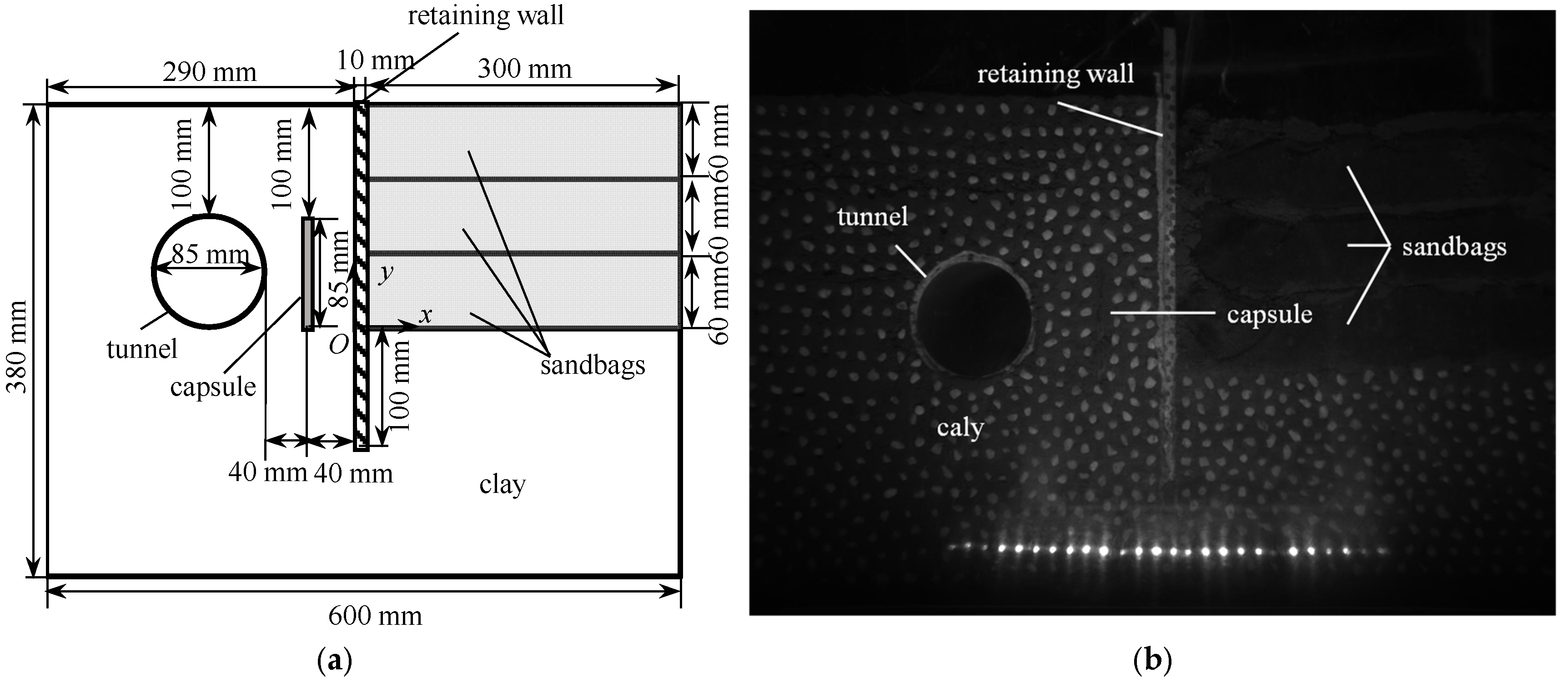
Two tests involving three excavation stages each, including the AC model (with A Capsule) test and the NC model (with No Capsule) test, were performed to analyze the influence of capsule pressurization on the structures and soil during excavation. All geometric parameters were identical between the two tests except for the presence of the capsule. A schematic of the AC model in the test is shown in Figure 1. According to the Unified Soil Classification System (USCS), the cohesive soil used is classified as CL-ML. The soil has a liquid limit of 30%, a plastic limit of 14.2%, and a plasticity index of 15.8. Its maximum dry density is 2.29 g/cm3, and the optimum water content is 15%. For sample preparation, a water content of 17% and a dry density of 1.6 g/cm3 were used. Strength parameters obtained from consolidated undrained triaxial tests are an internal friction angle φ = 30° and cohesion c = 6.6 kPa.
The retaining wall was fabricated from aluminum alloy, with a width of 200 mm and a thickness of 10 mm. It was embedded into the soil base to a depth of 100 mm. Its elastic modulus is 70 GPa, and its Poisson’s ratio is 0.33.
The tunnel is a hollow aluminum circular tube with a diameter of 85 mm and a wall thickness of 2 mm. The material properties of the tunnel are the same as those of the retaining wall. The crown of the tunnel is located 100 mm below the top surface of the model, and its closest side is 80 mm from the retaining wall.
The capsule was made from latex tubing, with a height of 85 mm and a diameter of approximately 6 mm. The elastic modulus of the capsule material is 50 kPa, and its Poisson’s ratio is 0.45. The capsule was positioned on the side of the organic glass, 40 mm from the retaining wall, and aligned at the same height as the tunnel.
During the sample preparation process, the soil was first compacted twice in layers of 5 cm thickness within the model container, followed by three compactions in layers of 6 cm until the target dry density was achieved. The retaining wall was installed after the first compaction stage. The tunnel and capsule were placed after the second compaction stage. The sandbags were positioned and compacted to the designed height after the third, fourth, and fifth soil compaction stages. To ensure adequate contact between successive soil layers, the interface of each layer was scarified to create a rough surface before placing the next layer. For image-based displacement measurement correlation, white particles were randomly affixed to the soil face visible through the plexiglass. To minimize friction between the soil model and the container walls, silicone oil was uniformly applied to the interior surfaces of the container.

2.3. Test Procedure

The centrifugal acceleration was initiated at 1 g and increased incrementally by 5 g steps until reaching the target level of 50 g. Following each 5 g increase, the acceleration was maintained constant until the model deformation stabilized.
In the NC model test, an excavation command was issued to the excavation device at each step, activating the vertical lifting device to raise one sandbag. This process simulated three excavation steps with depths of 60 mm, 120 mm, and 180 mm. In the AC model test, the same three excavation stages were carried out, but after each excavation step, the electromagnetic valve of the capsule pressurization equipment was opened to increase the pressure in the capsule from 0 to 100 kPa, 250 kPa, and 400 kPa, respectively. The three excavation depths (60, 120, 180 mm) were chosen to represent progressive, deep excavation in stages, with each step removing a significant volume (one sandbag). The corresponding capsule pressures (100, 250, 400 kPa) were designed to apply increasing levels of pressure with the increasing excavation depth. It is noted that all excavation or pressurization steps were conducted only after the soil deformation from the previous stage had stabilized (change in soil surface settlement of less than 0.1 mm over a period of 5 min at the model scale).
During the tests, the lateral side of the model was monitored and recorded as a series of images using a digital image capture system through the transparent organic glass. Displacements of the structures and soil were determined from these image sequences using a correlation-based analysis technique [28]. For the prototype scale, displacements and lengths are obtained by multiplying the model measurements by the g-level, which is 50 in this case. Stresses and strains in the model are identical to those in the prototype.
Coordinate systems were established with the origin at the intersection point of the pit and the retaining wall (Figure 1). The positive horizontal direction is defined to the right, and the positive vertical direction is defined upward.

2.4. Test Results

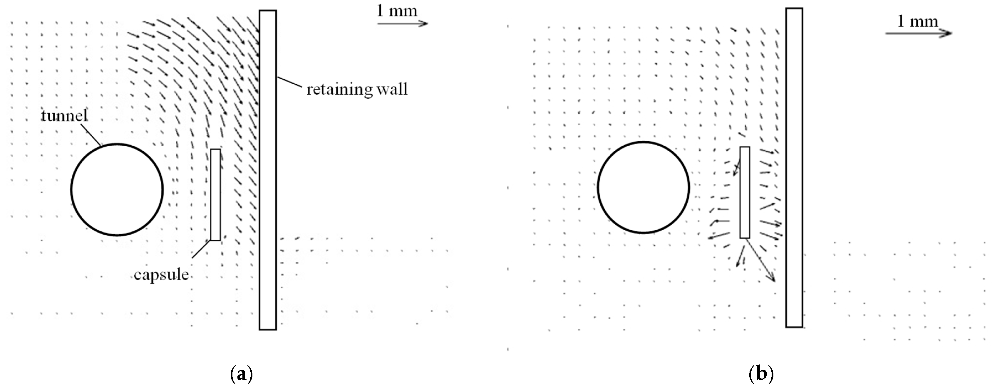
Figure 2a shows the displacement increment vectors of the model with a capsule after the second excavation in the centrifuge model test. It can be observed that the second excavation caused the soil to move outward and downward. The displacement is greatest near the retaining wall and gradually decreases to zero from the outside to the inside. Figure 2b shows the vectors of the same model after the second capsule pressurization. There is obvious deformation around the capsule after the second capsule pressurization. The displacement direction is normal to the capsule surface, and the magnitude decreases to zero with increasing distance from the capsule. Therefore, both excavation and capsule pressurization cause soil deformation, and the deformation occurs only within a limited area.
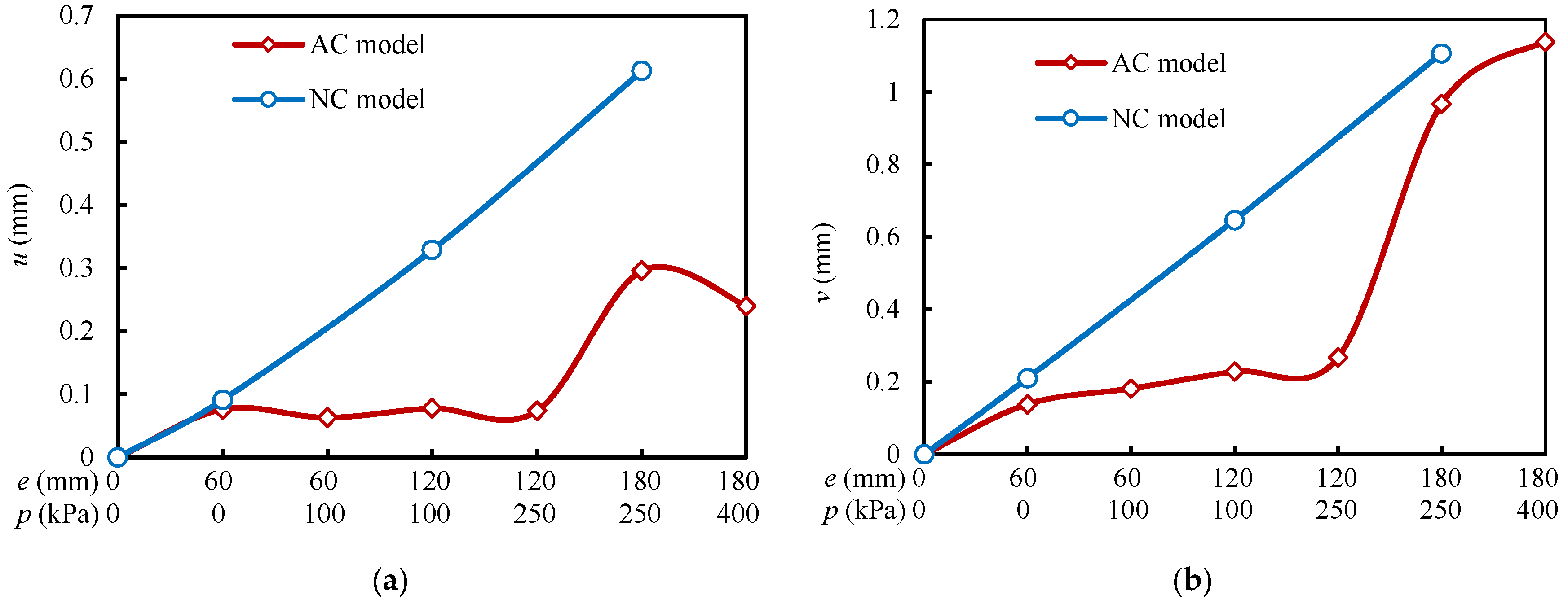
Figure 3 shows the history of displacement of the tunnels in the centrifuge model tests for both models. It can be seen that the horizontal and vertical displacements of the tunnel increase after each excavation step in the model without a capsule, indicating the tunnel moves outward and downward. Similarly, the tunnel also moves outward after each excavation in the model with a capsule, but the subsequent capsule pressurization causes the tunnel to move in the opposite direction. Capsule pressurization also causes the tunnel to move downward, but this effect is less significant compared to that of excavation. The observations show that the horizontal displacement in the model with a capsule is always less than that in the model without a capsule due to the capsule pressurization. It can be concluded that excavation of a foundation pit affects the adjacent tunnel, but the use of capsule pressurization can mitigate this effect.
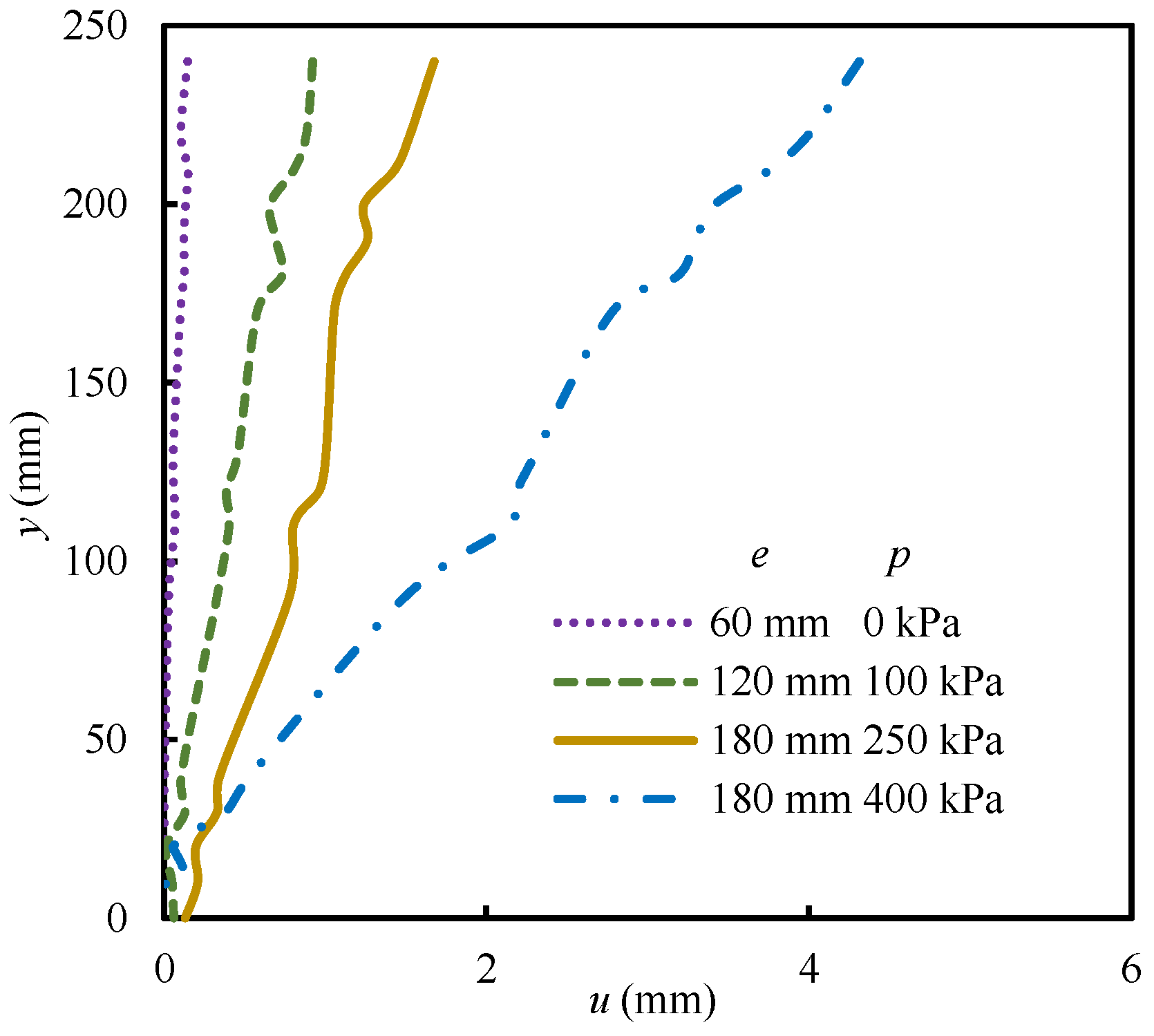
Figure 4 shows the distributions of retaining wall displacement for the model with a capsule in the centrifuge model test. It can be seen that the displacement consistently shows a linear distribution vertically under different excavation depths and capsule pressures. This indicates that the movement of the retaining wall can be considered as undergoing rigid body rotation during excavation and capsule pressurization.
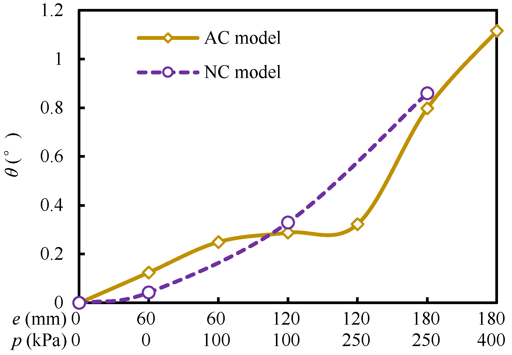
Figure 5 shows the histories of the rotation angle of the retaining wall for both models in the centrifuge model tests. It can be observed that the rotation angle in the model without a capsule increases with the excavation depth. For the model with a capsule, the retaining wall rotates after each excavation and each capsule pressurization. The rotation angles of the retaining wall in the two models were closely aligned immediately after each excavation step. It can be concluded that capsule pressurization has no significant effect on the rotation of the retaining wall.

3. Finite Element Analysis

Finite element analysis was performed based on the centrifuge model tests in order to study several influence factors and obtain more response results, including stresses and modulus in the structures and soil, which are difficult to measure accurately in physical tests.

3.1. Finite Element Model

The large-scale finite element software ABAQUS 2025 was utilized to develop two-dimensional plane strain numerical models based on the centrifuge test setup. The two-dimensional plane strain assumption is a widely accepted simplification for analyzing the cross-sectional behavior of long excavations where longitudinal variations are negligible [29]. During the centrifuge model tests, the soil deformation and structural responses were observed to be essentially uniform across the width of the model in the viewing direction, confirming that the plane strain condition was satisfactorily achieved.
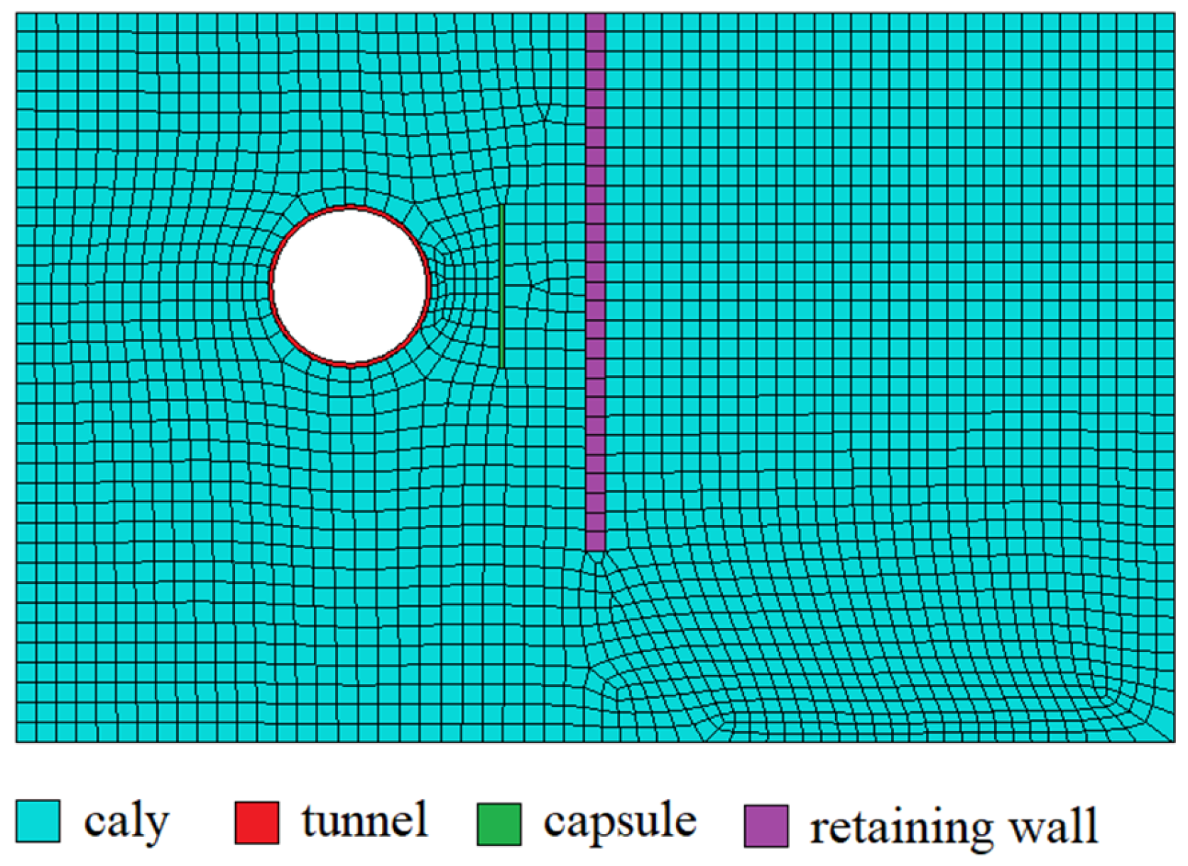
Figure 6 illustrates a typical finite element model representing the centrifuge test. The mesh is comprised of 4-node bilinear plane strain quadrilateral elements (CPE4). The left and right boundaries of the model are constrained in the horizontal direction, while the bottom boundary is fixed in all directions. The coordinate system in the FEM is consistent with that defined in the centrifuge model tests (Figure 1), with the origin at the intersection of the pit and retaining wall, x positive to the right, and y positive upward.
To investigate the effect of the position of the capsule, three different simulations were conducted for three different distances from the tunnel to the capsule. The ratios of the distance from the capsule to the retaining wall versus the distance from the outer boundary of the tunnel to the retaining wall, β, were 0.25, 0.5, and 0.75, respectively.

3.2. Constitutive Model of Materials

The macro-micro coupled constitutive model [30,31] was adopted to represent the soil behavior. This model is grounded in the coupling mechanism between macroscopic and microscopic soil properties, establishing a fabric evolution equation at the microscopic level and subsequently proposing a mapping relationship between fabric evolution and changes in macroscopic mechanical properties. The model has been validated against a wide range of soils and complex loading paths, including unloading, confirming its capability to replicate soil behavior under complex stress paths similar to those in this study. The equations of the model are presented using the following incremental stress–strain calculation formula:
d ε ˜ = 1 + ν E d σ ˜ ν E t r ( d σ ˜ ) I ˜ + ν t r σ ˜ I ˜ 1 + ν σ ˜ E 2 d E + σ ˜ t r σ ˜ I ˜ E d ν
E = E 0 + d E ν = ν 0 + d ν
E 0 = K p a σ 3 p a n ν 0 = a σ 3 p a m
d E E = n d σ 3 σ 3 d Ω d ν ν = m d σ 3 σ 3 + ν 0 d Ω
d Ω = 1 α + γ d γ
where ε ˜ and σ ˜ is the strain tensor and stress tensor, E is the secant Young’s modulus, ν is Poisson’s ratio, E0 is the initial modulus, ν0 is the initial Poisson’s ratio, σ3 is the minor principal stress, pₐ is the atmospheric pressure, Ω is the fabric state parameter, γ is the generalized shear strain. The physical meanings of the model parameters and the values adopted in this study are listed in Table 1.
A linear elastic model was used to simulate the stress–strain behavior of the retaining wall, tunnel, and capsule. The Young’s modulus and Poisson’s ratio values in the FEM matched those used in the centrifuge tests. Interfaces between soil and structures were modeled using hard contact in the normal direction and a friction model in the tangential direction, with friction coefficients set to 0.4. It has been verified that the effect of capsule modulus is small.

3.3. Simulation Procedure

The finite element analysis was conducted in several sequential steps. The initial step involved applying gravitational acceleration to the model in its initial state, prior to any excavation or pressurization. The gravitational acceleration was gradually increased to 490 m/s2 to simulate the 50 g condition in the centrifuge test.
Subsequent steps followed the sequence of the centrifuge test procedure. Each excavation step was simulated by deactivating a corresponding layer of soil elements. Each capsule pressurization step was simulated by applying a normal pressure to the internal surfaces of the capsule elements, matching the magnitudes used in the physical tests (100 kPa, 250 kPa, 400 kPa).

3.4. Validation

Numerical simulation results were compared with test data to evaluate the validity of the numerical models.
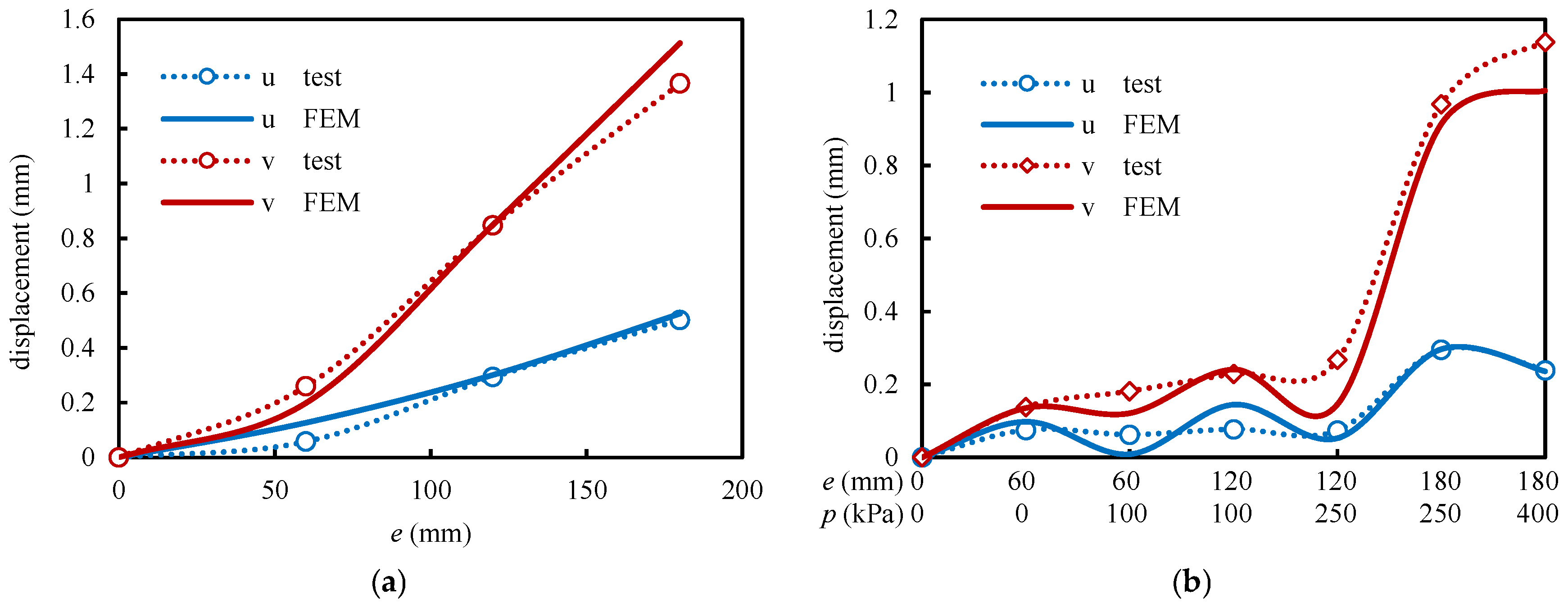
Figure 7 compares the histories of horizontal displacement of the tunnel for both models obtained from numerical analysis and centrifuge model tests. Overall, the trends are consistent, and the agreement is good. However, in the model with a capsule, the displacement measured in the early step of the test is slightly higher than the simulated value. This discrepancy may stem from local errors in displacement measurement during the test.
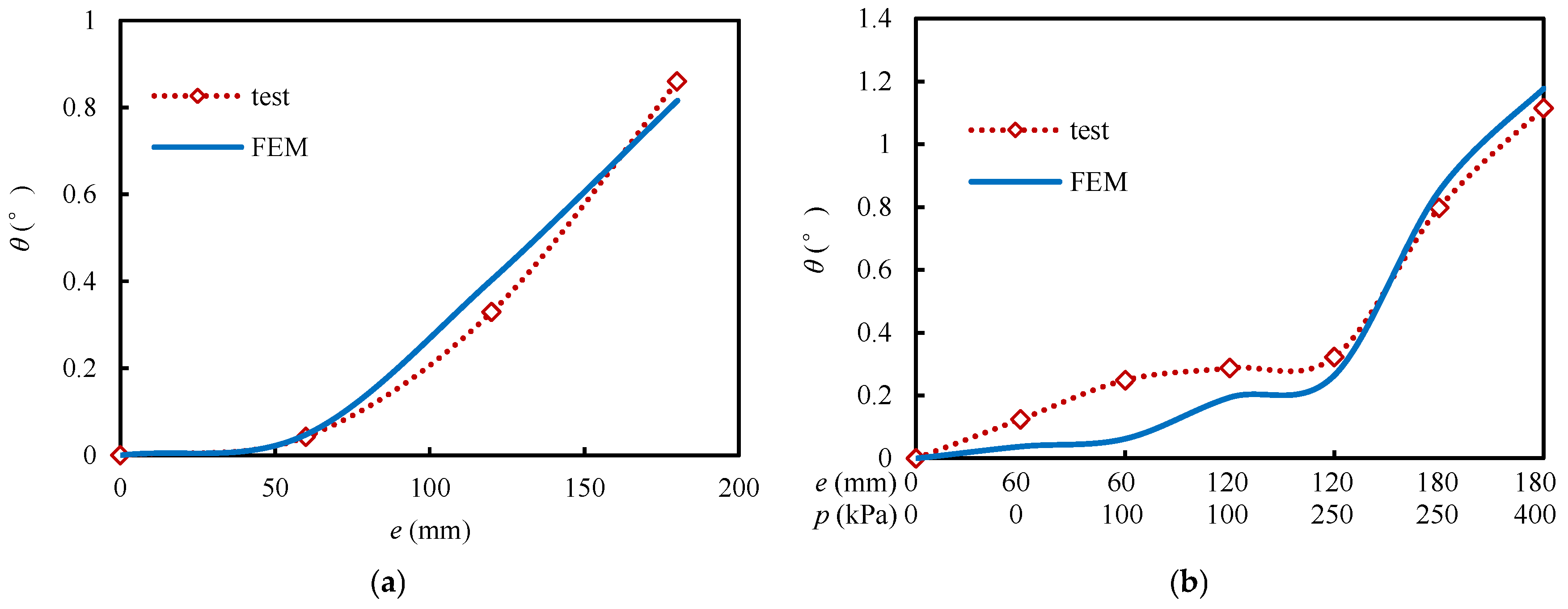
Figure 8 shows the comparison of the histories of the retaining wall rotation angle. Regardless of the presence of a capsule, the simulation curves closely match the test data points, indicating that the numerical model effectively captures the rotational response of the retaining wall.
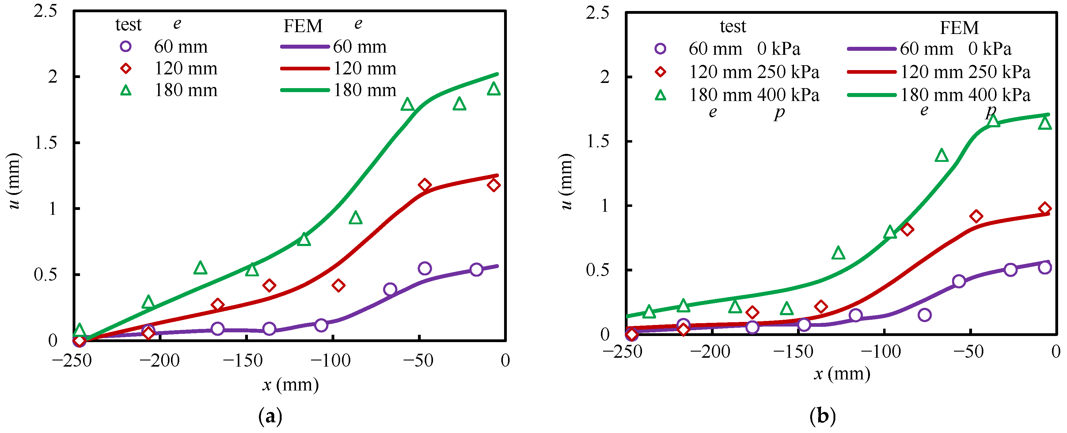
Figure 9 compares the displacement distributions of the models. The displacement distributions obtained from the simulation are highly consistent with the test results, including for different excavation depths and different capsule pressures. The simulation accurately reproduces the deformation characteristics observed in the tests.
In summary, validation through these three aspects shows that the numerical model can reliably simulate the response of the tunnel, retaining wall, and soil in both models and can be used for further in-depth analysis.

4. Rules and Mechanisms

4.1. Stress–Deformation Rules During Excavation

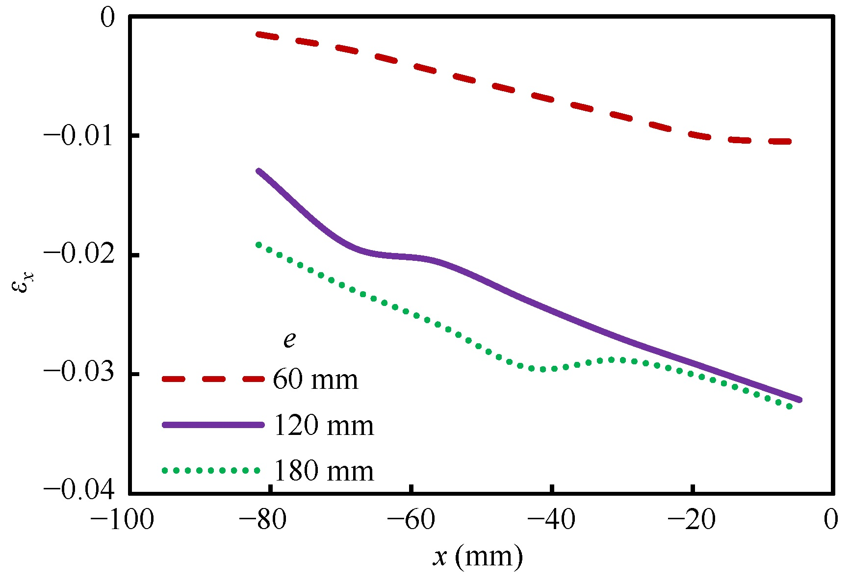
Figure 10 shows the distributions of horizontal strain of the model without a capsule in the centrifuge model test. It can be observed that tensile strain occurs in the soil inside the retaining wall after each excavation step, and the tensile strain decreases with increasing distance from the retaining wall. Furthermore, the greater the excavation depth, the larger the tensile strain. Excavation induces tensile deformation in the soil between the retaining wall and the tunnel, resulting in an outward displacement of the tunnel. It can be concluded that the impact of excavation is transferred to the tunnel through the interaction of the retaining wall–soil and soil–tunnel systems. This impact becomes more pronounced as the excavation depth increases.
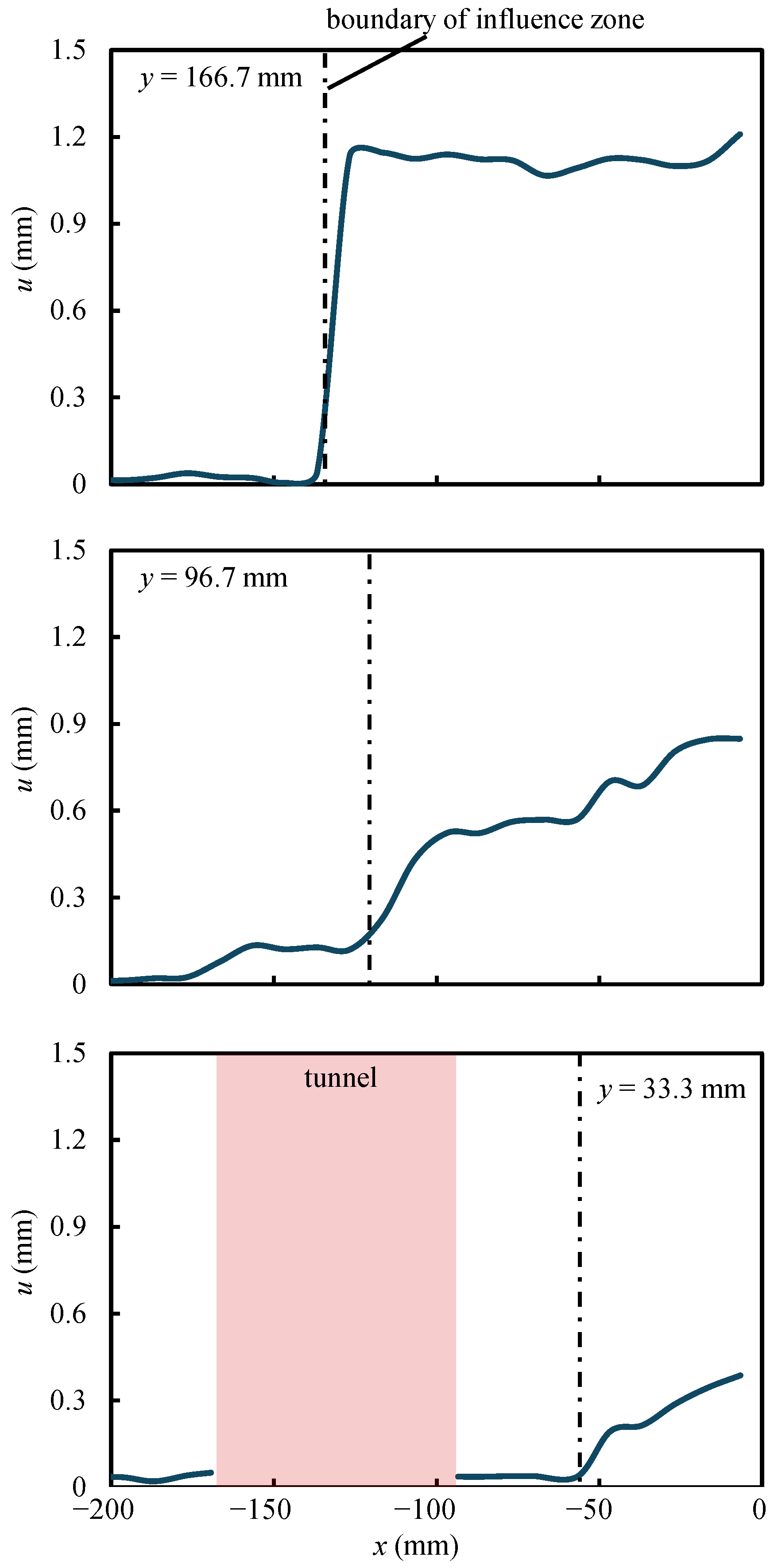
Figure 11 shows the distributions of horizontal displacement of the model without a capsule in the centrifuge model test. Displacement increases gradually from the interior towards the retaining wall. The displacement approaches zero at locations far from the retaining wall, indicating that the influence of excavation during the test is confined to a limited area. The boundary of this influence zone is determined by an inflection point where displacement begins to increase due to excavation, marked by a dotted line in Figure 11. In practical engineering, monitoring of the soil and structures affected during excavation should focus on this zone. This boundary can serve as a useful reference for preventing safety issues during foundation pit excavation.
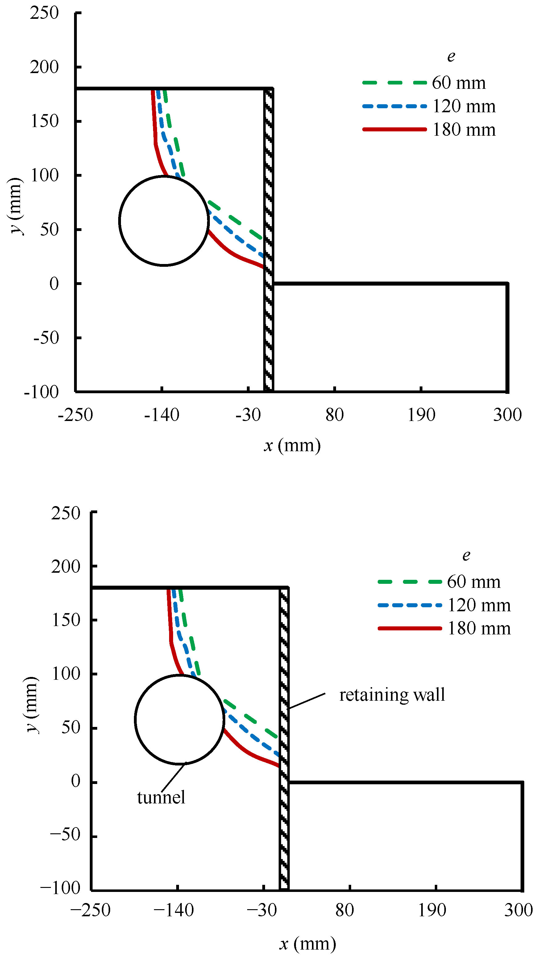
Figure 12 shows the influence zones at different excavation depths for the model without a capsule. Deformation is confined to a specific, limited area during excavation. The boundary of the influence zone starts from the intersection of the tunnel axis and the ground surface, passes through the tunnel, and ends near the middle-lower part of the retaining wall. As the excavation depth increases, the influence zone expands. Therefore, foundation pit excavation affects both the tunnel and the adjacent soil, and deeper excavation causes a larger area to be affected.
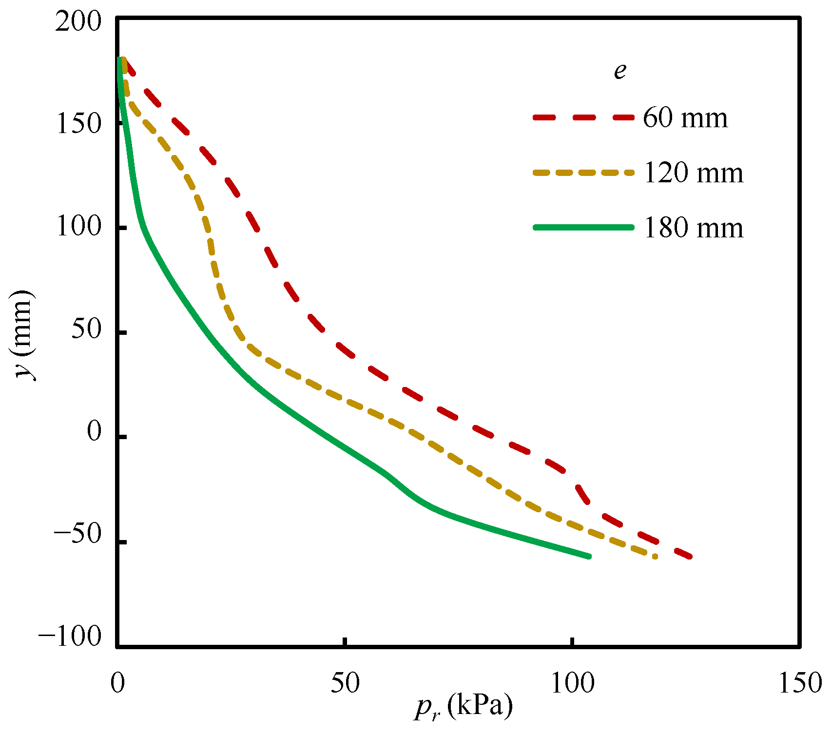
Figure 13 shows the distributions of earth pressure on the retaining wall of the model without a capsule in the FEM. It can be seen that the earth pressure on the retaining wall shows an approximately linear distribution, increasing from top to bottom. As the excavation depth increases, the earth pressure at each height of the retaining wall decreases. Therefore, the excavation process leads to a reduction in the force exerted on the retaining wall.
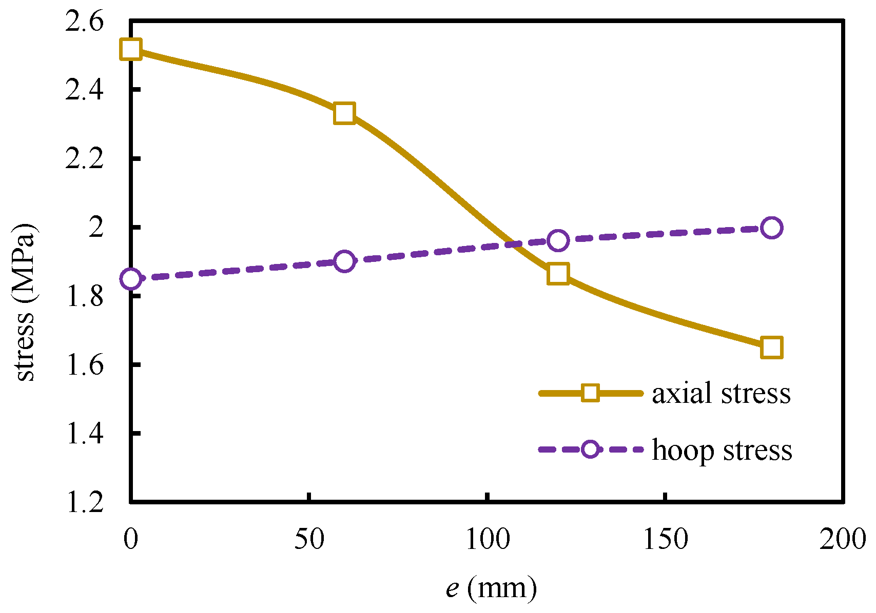
Figure 14 shows the histories of stress on the side of the tunnel facing the retaining wall for the model without a capsule in the FEM. Throughout the excavation, both the hoop and axial stresses maintain compressive states. However, the hoop and axial stresses are affected differently by excavation. After each excavation, the axial stress decreases, while the hoop stress increases. Furthermore, compared to the hoop stress, the axial stress is more significantly affected by the excavation depth. This indicates that excavation makes the stress state on the outer side of the tunnel increasingly dominated by hoop stress.

4.2. Capsule Influence Rules

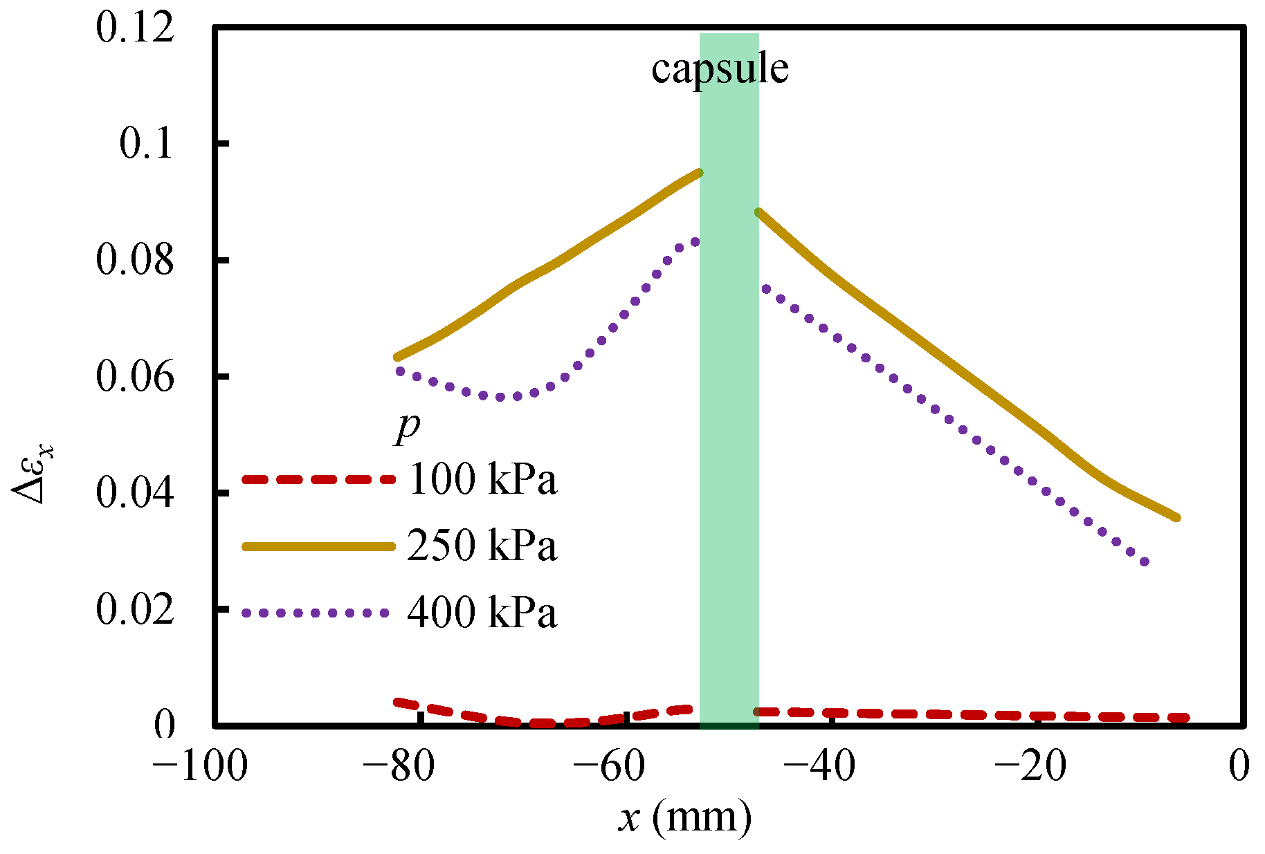
Figure 15 shows the distributions of the difference in horizontal strain between the two models in the centrifuge model test. Capsule pressurization causes compressive deformation in the surrounding soil. The compressive deformation induced by capsule pressurization is greatest near the capsule and decreases with increasing distance from the capsule. As the capsule pressure increases, the effect of pressurization on the deformation of the surrounding soil becomes greater. It can be concluded that capsule pressurization significantly influences soil deformation, with the effect decaying with distance from the capsule and increasing with applied pressure.
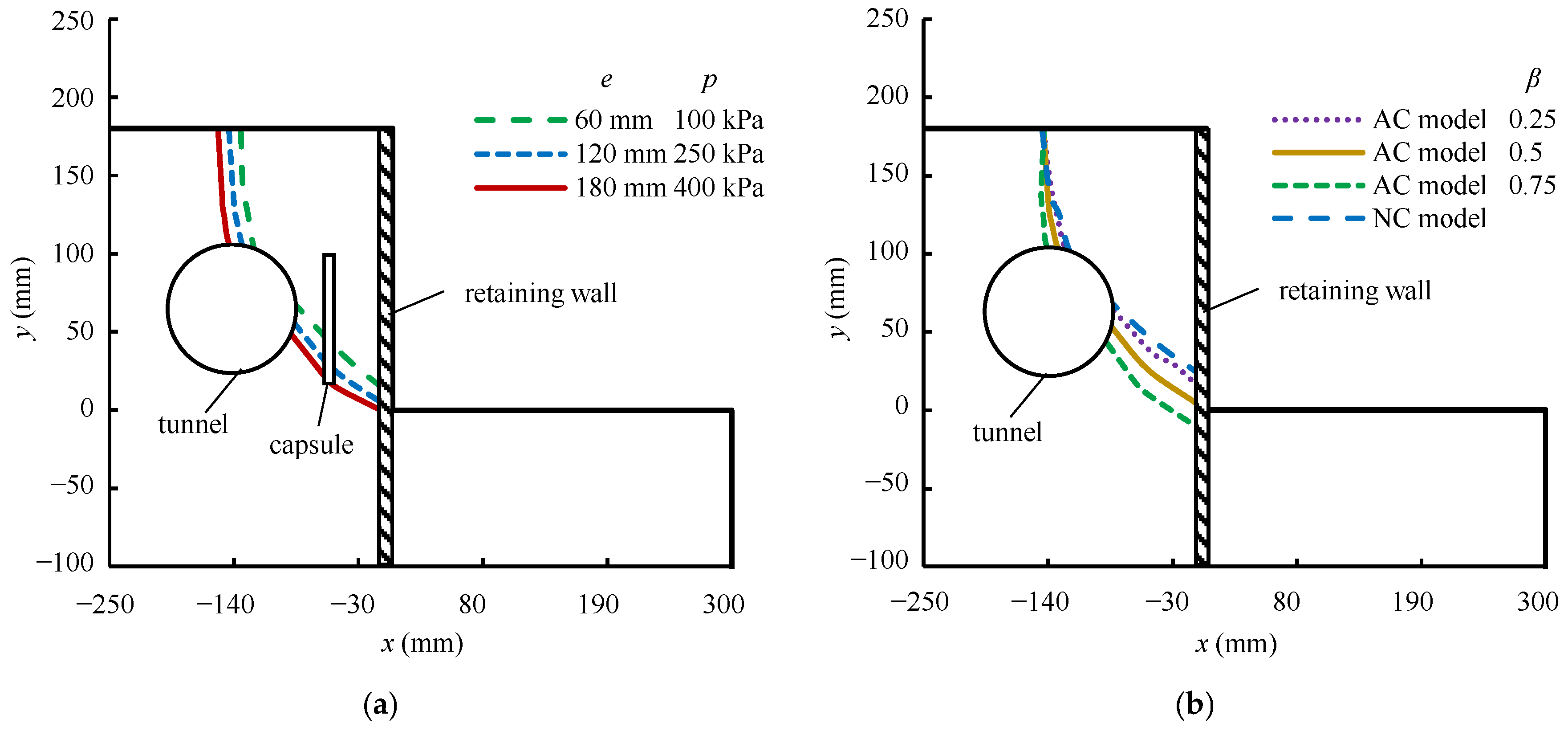
The influence zones for the model with a capsule were determined using the same method as for the model without a capsule. Figure 16a shows the influence zone of the model with a capsule at different excavation depths and capsule pressures in the centrifuge model test. Similar to the model without a capsule, the influence zone of the model with a capsule also expands with increasing excavation depth. Figure 16b shows the influence zones for models with a capsule at different positions and the model without a capsule. Among them, the influence zones for the models with β values of 0.25 and 0.75 were determined based on the displacement distributions from the FEM. A comparison shows that the influence zones for the models with a capsule have a similar shape but a slightly larger extent than those without a capsule. As the distance between the capsule and the tunnel decreases, the influence zone expands. Compared to the influence zone above the tunnel, the influence zone between the tunnel and the retaining wall is more significantly affected by the presence and position of the capsule. It can be concluded that capsule pressurization expands the influence zone of soil between the tunnel and the retaining wall. Furthermore, capsules positioned closer to the tunnel exert a greater influence on the soil.
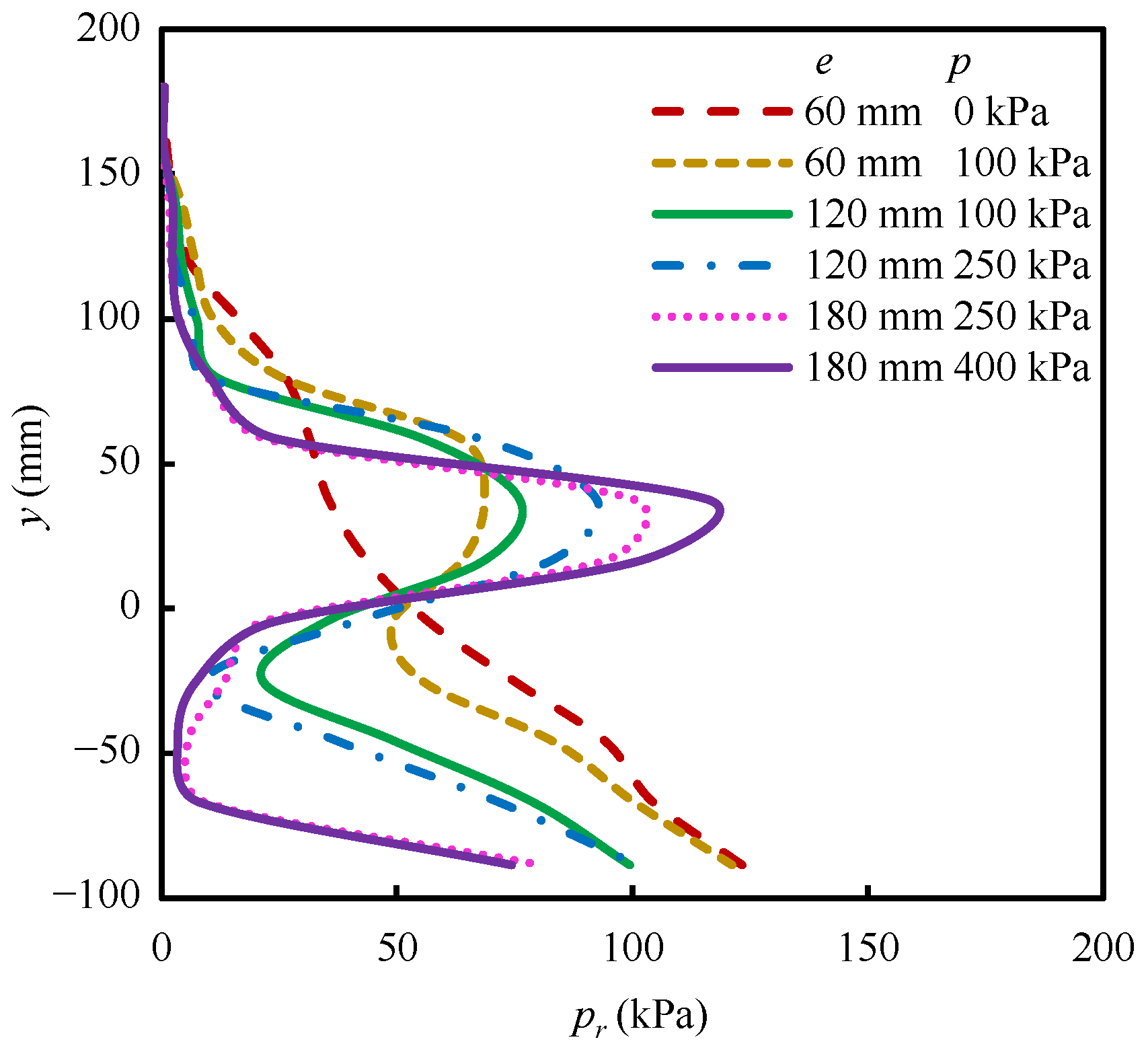
Figure 17 shows the distributions of earth pressures on the retaining wall of the model with a capsule in the FEM. It can be observed that the earth pressure distribution transitions from a linear to a non-linear profile following the initial capsule pressurization. After each capsule pressurization, the earth pressure near the capsule increases, while the earth pressure above and below the capsule decreases. The stress increase from the capsule is transferred through the soil to the retaining wall, inducing higher earth pressure on the proximal section. This leads to an increased rotation angle of the wall and a corresponding reduction in earth pressure on other parts. Similarly, the earth pressure closer to the capsule increases while it decreases further away after the second and third excavations. This phenomenon can be attributed to the stress redistribution in the soil induced by excavation, which thereby amplifies the effect of capsule pressurization on the earth pressure distribution. It can be concluded that the earth pressure distribution on the retaining wall is significantly influenced by capsule pressurization, with the effect being amplified by both higher capsule pressure and greater excavation depth.
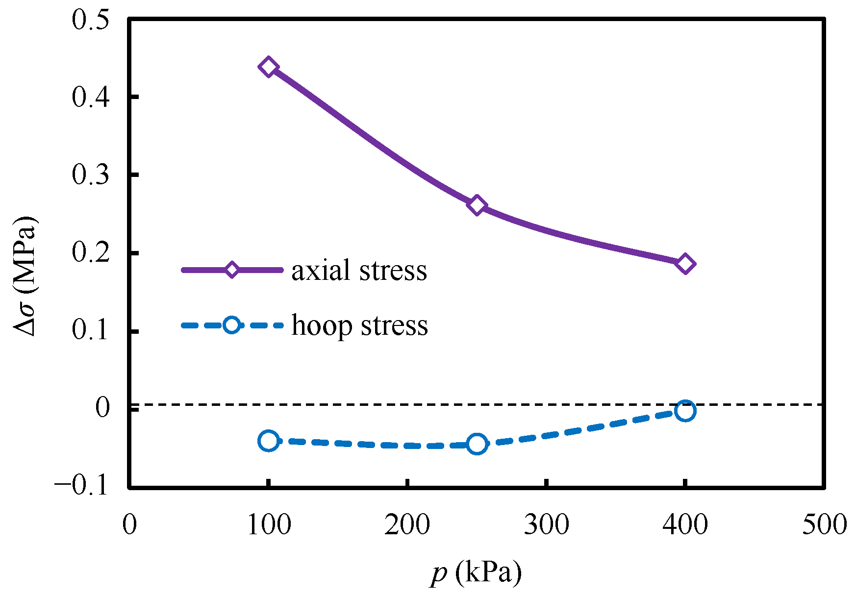
Figure 18 shows the difference in stress on the side of the tunnel facing the retaining wall in the FEM. Capsule pressurization reduces the hoop stress while increasing the axial stress on the tunnel side facing the retaining wall. The influence of capsule pressurization dominates the axial stress more than the hoop stress. As the internal capsule pressure increases, the influence of the capsule on both stresses gradually diminishes. Therefore, capsule pressurization affects the stress state of the tunnel, but this influence gradually decreases with capsule pressure.
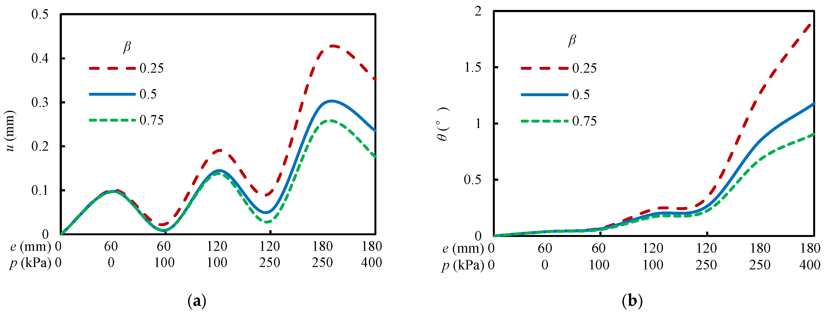
To analyze the effect of capsule position on the structures of the model, the tunnel displacement and retaining wall rotation angle with different capsule positions in the FEM were calculated. Figure 19a shows a comparison of the histories of tunnel horizontal displacement. If the distance between the capsule and the tunnel increases, the movement of the tunnel caused by capsule pressurization decreases, and the outward displacement caused by the subsequent excavation increases. In other words, a greater capsule-tunnel distance leads to a larger outward tunnel displacement per excavation–pressurization cycle. Figure 19b shows a comparison of the histories of the retaining wall rotation angle. A greater distance between the tunnel and the capsule amplifies the retaining wall rotation induced by capsule pressurization, thereby resulting in a larger rotation amplitude during the subsequent excavation. This indicates that increasing the distance between the capsule and tunnel leads to more pronounced rotation of the retaining wall. It can be concluded that a capsule positioned closer to the tunnel has a greater effect on the tunnel and a smaller effect on the retaining wall. It should be noted that the influence of capsule position (β) was investigated numerically due to the complexity and resource intensity of conducting multiple centrifuge tests. The numerical model was rigorously validated against the centrifuge test for the case of β = 0.5. This validation provides a reliable basis for extending the analysis to other capsule positions. While the effect of capsule-tunnel distance is clearly demonstrated through the numerical study, future experimental work incorporating multiple capsule positions would provide valuable direct validation and further refine the understanding of optimal capsule placement.

4.3. Mechanism of the Capsule

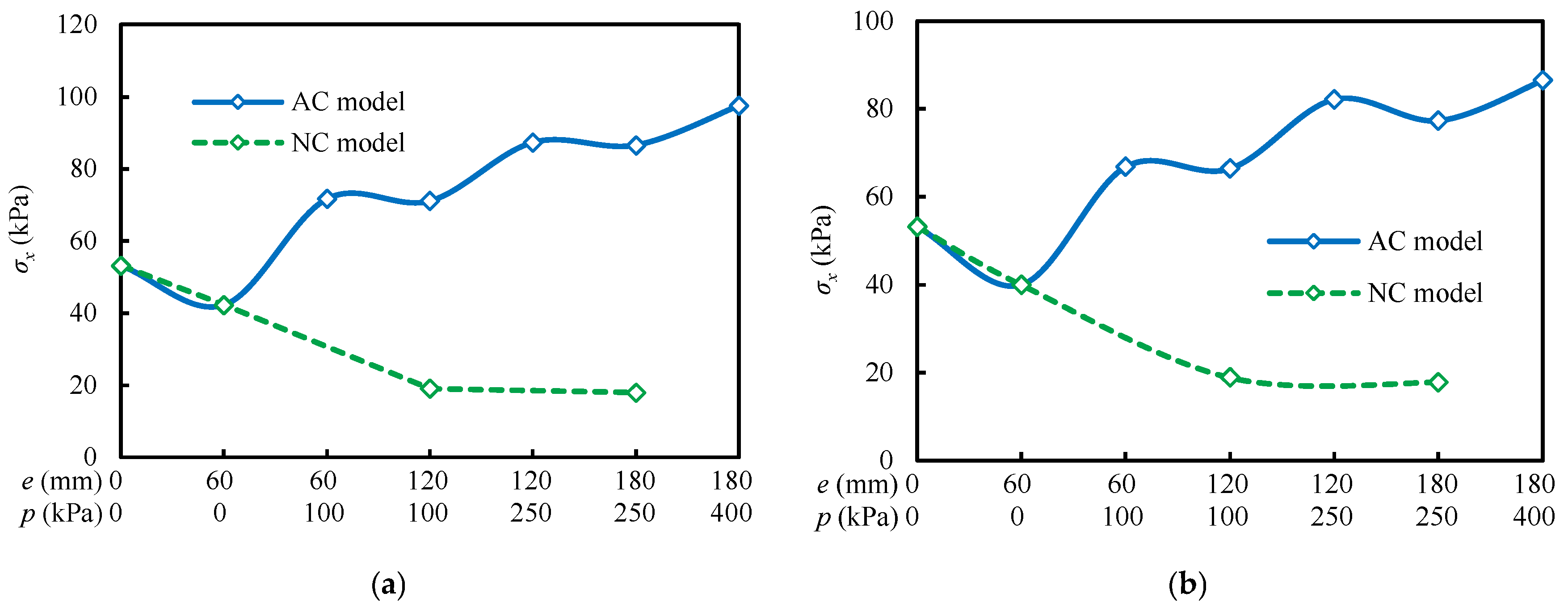
Recent studies have advanced the understanding of how controlled pressures mitigate ground disturbance [32] and how materials respond to complex loading paths [33]. Building upon this knowledge, this section investigates the specific mechanism through which capsule pressurization alters the stress–deformation response of the soil–tunnel system during multi-step excavation. In this study, due to technical constraints in centrifuge model tests, validated numerical simulations were used to analyze the changes in soil modulus and stress. The consistency between measured and simulated deformation (Figure 7, Figure 8 and Figure 9) supports the reliability of these numerical results. Figure 20 shows the histories of horizontal stress in soil elements near the capsule for the two models in the FEM. It can be observed that the horizontal stress decreases with increasing excavation depth in the model without a capsule. The model with a capsule exhibits an identical magnitude of horizontal stress reduction after the first excavation step as the model without a capsule. However, after each capsule pressurization, the horizontal stress in the model with a capsule increases. Moreover, the decreases in horizontal stress after the second and third excavation steps in the model with a capsule are smaller. Therefore, capsule pressurization reduces the magnitude of stress decrease in the surrounding soil during subsequent excavation.
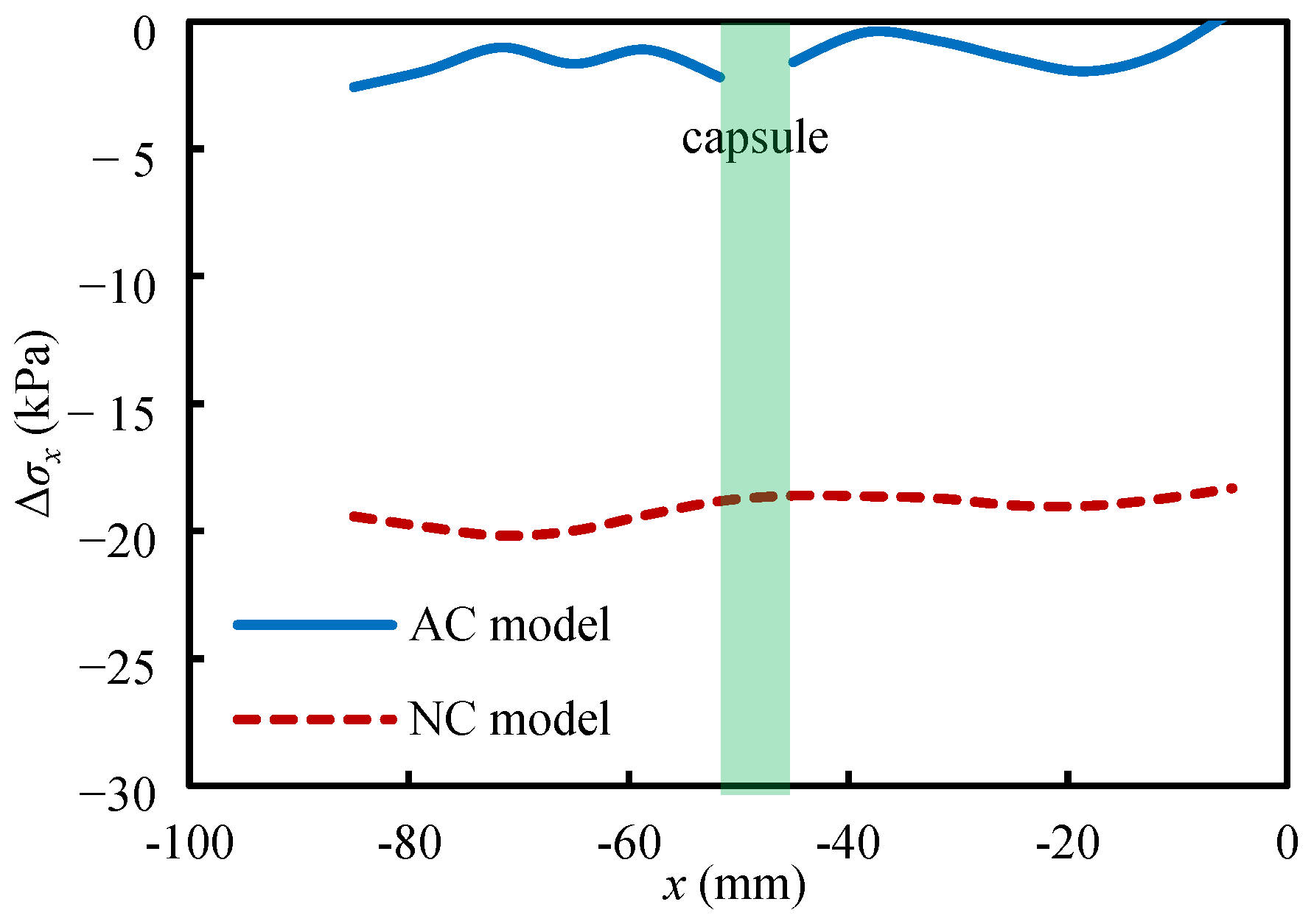
Figure 21 shows the distributions of horizontal stress increment after the second excavation step for the two models in the FEM. Both models exhibit relatively uniform horizontal stress distributions between the tunnel and the retaining wall. The magnitude of the horizontal stress increment in the model with a capsule is significantly lower than that in the model without a capsule. This indicates that capsule pressurization reduces the stress increment from subsequent excavation. Consequently, the deformation of the soil between the capsule and the tunnel is reduced, thereby attenuating the extent to which the soil transfers the impact of excavation to the tunnel.
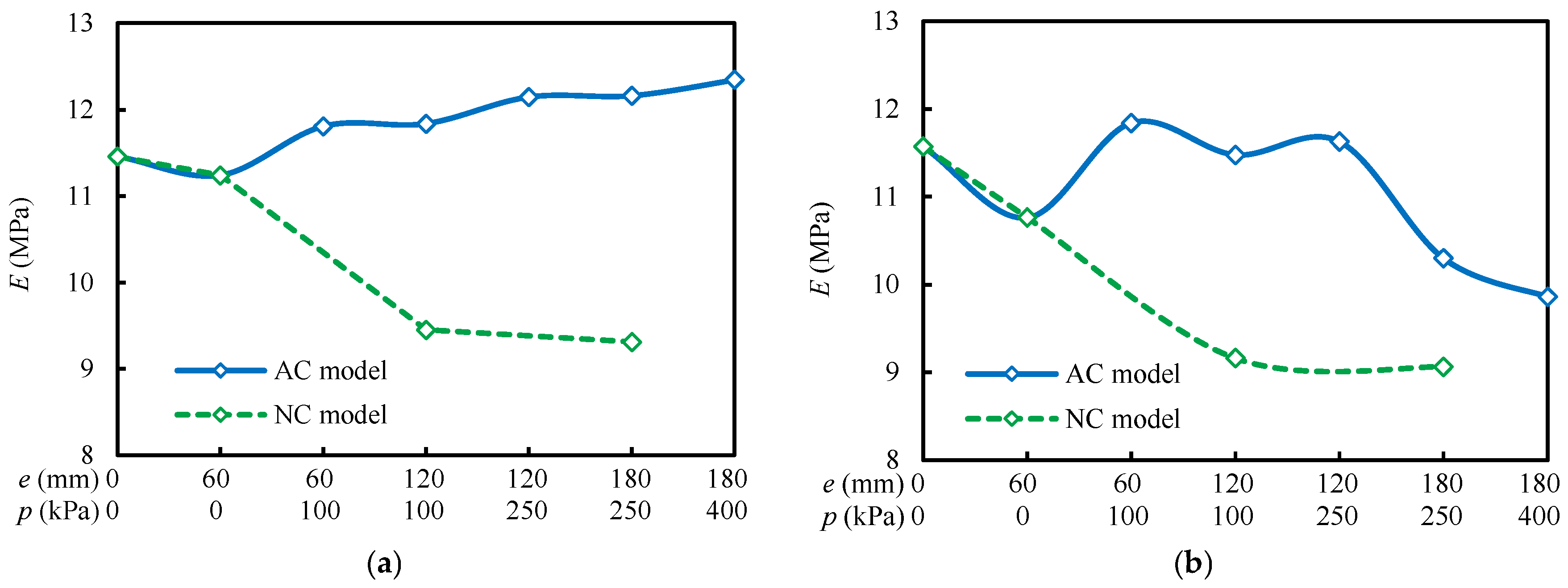
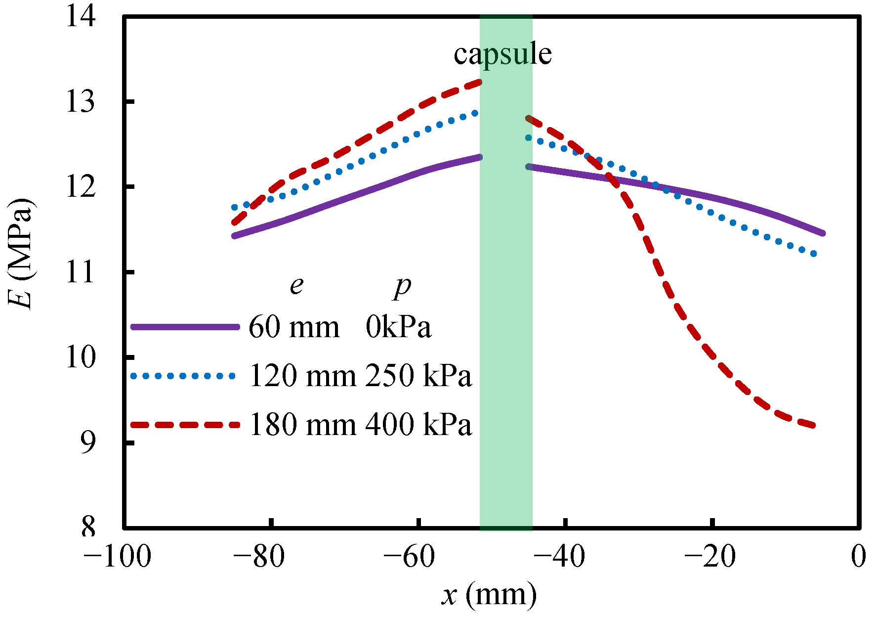
Figure 22 shows the histories of the secant modulus of soil elements near the capsule for the two models in the FEM. It can be observed that in the model without a capsule, the secant modulus decreases after each excavation step. The reduction in soil modulus is most pronounced during the second excavation step and more modest during the third. This differential effect highlights the distinct responses of soil layers at different excavation depths. Each excavation step also reduces the modulus in the model with a capsule, but the modulus can increase noticeably after each capsule pressurization. This is because pressurization increases the minor principal stress in the soil, improving the modulus of the soil on both sides of the capsule. However, the modulus of the soil on the outer side of the capsule decreases during the final pressurization. It is hypothesized that excessive pressure may induce significant fabric evolution in the outer soil, reducing its modulus. In contrast, the soil confined between the capsule and the tunnel exhibits a consistent increase in modulus. Throughout the excavation and pressurization process, the modulus of the soil in the model with a capsule is always higher than that in the model without a capsule. It can be concluded that capsule pressurization makes the soil between it and the tunnel stiffer and less deformable, resulting in less influence on the tunnel.
Figure 23 shows the horizontal distributions of the secant modulus of the model with a capsule in the FEM. A clear spatial distribution shows the highest secant modulus of the soil at the capsule interface, decreasing bidirectionally. Within the confined zone between the capsule and tunnel, modulus increases with excavation depth and pressure due to enhanced confinement; conversely, near the retaining wall, modulus reduction occurs in some elements due to stress redistribution. Therefore, the effect of capsule pressurization on soil properties varies significantly depending on the soil location.
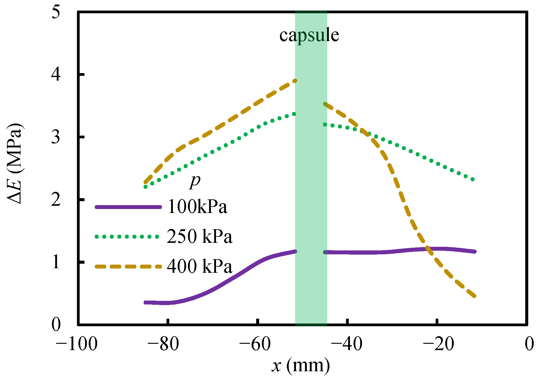
Figure 24 shows the horizontal distributions of the difference in modulus of the soil between the two models. It can be seen that the modulus in the model with a capsule is higher everywhere compared to the model without a capsule. Moreover, the increase in modulus of the soil is greatest near the capsule and decreases towards both sides. Between the capsule and the tunnel, higher capsule pressure leads to a greater increase in modulus induced by pressurization. It can be concluded that capsule pressurization increases the modulus of the surrounding soil, thereby reducing the soil deformation caused by subsequent excavation. This results in less impact on the tunnel during subsequent excavation, ultimately reducing the tunnel movement.
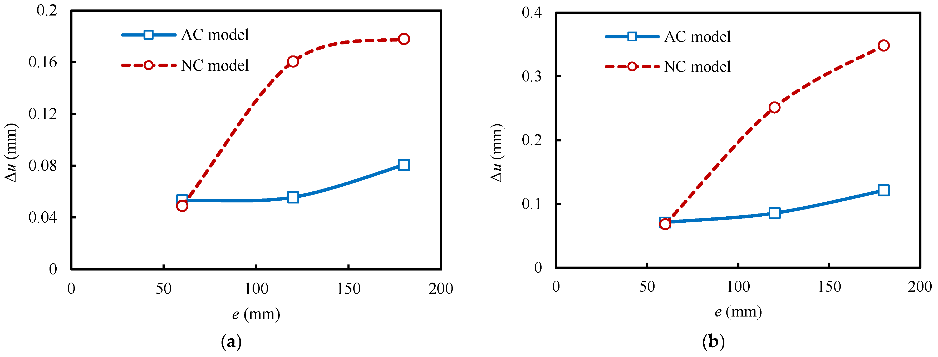
Figure 25 shows the displacement increments of the tunnel after each excavation step for the two models in centrifuge model tests. It can be observed that both the horizontal and vertical displacement increments in the model with a capsule are significantly lower than those in the model without a capsule. This indicates that capsule pressurization reduces the deformation of the surrounding soil during subsequent excavation, validating the previous analysis and conclusions. In essence, the excavation impact propagates to the tunnel via wall–soil and soil–tunnel interactions. Capsule pressurization mitigates the response of the tunnel by ensuring the surrounding soil experiences a smaller reduction in horizontal stress and exhibits a higher modulus during subsequent excavation. This enhanced state of the soil produces smaller deformation, which ultimately transfers less of the excavation effect to the tunnel and controls its displacement. While the established qualitative mechanism is robust, future work should focus on developing quantitative correlations between the reduction in soil stress (Δσₓ), the increase in soil modulus (ΔE), and the resulting reduction in tunnel displacement, to inform precise design guidelines.
The capsule technology is validated as an effective reinforcement measure under multi-step excavation. The distance between the capsule and the tunnel is a paramount design factor. A smaller distance between the capsule and tunnel yields greater control efficacy. After each excavation step, tunnel displacement should be monitored. Capsule pressurization should then be implemented promptly, with the pressure magnitude quantitatively informed by the monitored displacement data, to dynamically and precisely control the soil–tunnel interaction.

5. Conclusions

In this study, the response of the structures and soil during multi-step excavation and capsule pressurization is investigated by using centrifuge model tests and numerical analyses. The main conclusions are summarized as follows:
(1)
The responses of both the structures and the soil undergo a cumulative process induced by multiple excavation steps, which is a more realistic scenario than the commonly studied single-step simplification. Deformation of the soil due to each excavation step is confined to an influence zone. As the excavation deepens, the influence zone progressively expands. During this process, the tunnel moves outward while the retaining wall undergoes clockwise rotation. Concurrently, the stress on the tunnel changes, and the earth pressure on the retaining wall decreases. In engineering practice, monitoring efforts should be concentrated within the influence zone to enable early warning and timely intervention.
(2)
The earth pressure on the retaining wall and the stress state of the tunnel are significantly influenced by capsule pressurization, with the effect being amplified by greater excavation depth. Increasing the distance between the capsule and tunnel leads to more pronounced rotation of the retaining wall and tunnel displacement per excavation–pressurization cycle.
(3)
The novel capsule pressurization technology was systematically investigated in this study. Capsule pressurization significantly leads to compressive deformation of the surrounding soil and expands the influence zone between the tunnel and the retaining wall, with the effect decaying with distance from the capsule and increasing with applied pressure.
(4)
The excavation impact propagates to the tunnel via wall–soil and soil–tunnel interactions. Capsule pressurization mitigates the response of the tunnel by ensuring the surrounding soil experiences a smaller reduction in horizontal stress and exhibits a higher modulus during the next excavation. This enhanced state of the soil produces smaller deformation, which ultimately transfers less of the excavation effect to the tunnel and controls its displacement. For practical implementation, a real-time displacement monitoring system is recommended to guide the timing and magnitude of pressurization. Capsule pressure should be increased progressively with excavation depth, enabling adaptive control of tunnel displacement.

Author Contributions

Methodology, B.X.; software, S.L.; investigation, S.L.; formal analysis, S.L.; resources, G.Z.; writing—original draft preparation, B.X., S.L. and G.Z.; writing—review and editing, B.X., S.L. and G.Z.; visualization, Y.X., X.M. and Y.Z.; supervision, G.Z.; project administration, B.X. All authors have read and agreed to the published version of the manuscript.

Funding

This research and the APC was funded by the National Natural Science Foundation of China grant number 524B2132.

Data Availability Statement

The datasets generated during and/or analyzed during the current study are available upon reasonable request. The following URL presents the photographs of the tests in this paper. https://cloud.tsinghua.edu.cn/d/7b3539caad2d47a1afda/, accessed on 17 February 2026.

Acknowledgments

The study was funded by the National Natural Science Foundation of China.

Conflicts of Interest

Author Bingfeng Xiao, Yi Xie, Xiaobing Mao and Yijun Zhu were employed by the China Railway Eryuan Engineering Group Co., Ltd. The remaining authors declare that the research was conducted in the absence of any commercial or financial relationships that could be construed as a potential conflict of interest.

References

  1. Liu, B.; Wu, W.; Lu, H.; Chen, S.; Zhang, D. Effect and control of foundation pit excavation on existing tunnels: A state-of-the-art review. Tunn. Undergr. Space Technol. 2024, 147, 105704. [Google Scholar] [CrossRef] [Scilit]
  2. Vinoth, M.; Aswathy, M. Behaviour of existing tunnel due to adjacent deep excavation-a review. Int. J. Geotech. Eng. 2022, 16, 1132–1151. [Google Scholar] [CrossRef] [Scilit]
  3. Tan, Y.; Li, X.; Kang, Z.; Liu, J.; Zhu, Y. Zoned excavation of an oversized pit close to an existing metro line in stiff clay: Case study. J. Perform. Constr. Facil. 2015, 29, 04014158. [Google Scholar] [CrossRef] [Scilit]
  4. Cheng, X.; Hong, T.; Lu, Z.; Cheng, X. Characterization of underlying twin shield tunnels due to foundation-excavation unloading in soft soils: An experimental and numerical study. Appl. Sci. 2021, 11, 10938. [Google Scholar] [CrossRef] [Scilit]
  5. Wei, G.; Zhang, X.; Lin, X.; Hua, X. Variations of transverse forces on nearby shield tunnel caused by foundation pits excavation. Rock Soil Mech. 2020, 41, 635–644. [Google Scholar] [CrossRef]
  6. Peng, S.; Li, C.; Luo, G.; Li, Y.; Pan, H.; Cao, H.; Liang, S. Laboratory investigation effects of control measures for leakage-induced erosion on seepage interactions in defective underground structures. Tunn. Undergr. Space Technol. 2025, 161, 106593. [Google Scholar] [CrossRef] [Scilit]
  7. Sharafat, A.; Tanoli, W.; Zubair, M.; Mazher, K. Digital Twin-Driven Stability Optimization Framework for Large Underground Caverns. Appl. Sci. 2025, 15, 4481. [Google Scholar] [CrossRef] [Scilit]
  8. Jia, C.; Cheng, S.; Li, L.; Chen, Y. Seismic ahead-prospecting method based on delayed blasting excitation in the tunnel face: A case study. Tunn. Undergr. Space Technol. 2025, 161, 106577. [Google Scholar] [CrossRef] [Scilit]
  9. Zhang, D.; Xie, X.; Li, Z.; Zhang, J. Simplified analysis method for predicting the influence of deep excavation on existing tunnels. Comput. Geotech. 2020, 121, 103477. [Google Scholar] [CrossRef] [Scilit]
  10. Zhuang, Y.; Cui, X.; Hu, S. Numerical simulation and simplified analytical method to evaluate the displacement of adjacent tunnels caused by excavation. Tunn. Undergr. Space Technol. 2023, 132, 104879. [Google Scholar] [CrossRef] [Scilit]
  11. Wang, Q.; Jiang, M.; Feng, D.; Lu, H.; Yao, M.; Yang, A.; Cao, M.; Ma, Z. Numerical investigation of the influence of foundation pit excavation on the deformation of underlying tunnels based on a multi-factor orthogonal test. Buildings 2024, 14, 2618. [Google Scholar] [CrossRef] [Scilit]
  12. Zheng, G.; Du, Y.; Cheng, X.; Diao, Y.; Deng, X.; Wang, F. Characteristics and prediction methods for tunnel deformations induced by excavations. Geomech. Eng. 2017, 12, 361–397. [Google Scholar] [CrossRef] [Scilit]
  13. Huang, X.; Schweiger, H.; Huang, H. Influence of deep excavations on nearby existing tunnels. Int. J. Geomech. 2013, 13, 170–180. [Google Scholar] [CrossRef] [Scilit]
  14. Yang, T.; Tong, L.; Pan, H.; Wang, Z.; Chen, X.; Li, H. Effect of excavation sequence on uplift deformation of underlying existing metro tunnel. J. Perform. Constr. Facil. 2021, 35, 04021003. [Google Scholar] [CrossRef] [Scilit]
  15. Shi, J.; Fu, Z.; Guo, W. Investigation of geometric effects on three-dimensional tunnel deformation mechanisms due to basement excavation. Comput. Geotech. 2019, 106, 108–116. [Google Scholar] [CrossRef] [Scilit]
  16. Zhu, D.; Griffiths, D.; Fenton, G.; Huang, J. Probabilistic stability analyses of two-layer undrained slopes. Comput. Geotech. 2025, 182, 107178. [Google Scholar] [CrossRef] [Scilit]
  17. Li, S.; Zhang, Y.; Cao, M.; Wang, Z. Study on Excavation Sequence of Pilot Tunnels for a Rectangular Tunnel Using Numerical Simulation and Field Monitoring Method. In Rock Mechanics and Rock Engineering; Springer: Cham, Switzerland, 2022; Volume 55, pp. 3507–3523. [Google Scholar] [CrossRef] [Scilit]
  18. Sharma, J.; Hefny, A.; Zhao, J.; Chan, C. Effect of large excavation on deformation of adjacent MRT tunnels. Tunn. Undergr. Space Technol. 2001, 16, 93–98. [Google Scholar] [CrossRef] [Scilit]
  19. Li, Z.; Yang, K.; Xu, X.; Yang, Y.; Jiang, Y.; Tong, L.; Chen, Y. Investigation of metro tunnel response to multiple adjacent large excavations in soft soils. Tunn. Undergr. Space Technol. 2024, 152, 105935. [Google Scholar] [CrossRef] [Scilit]
  20. Wang, C.; Liang, R.; Wu, J.; Li, Z.; Ding, Z.; Wu, W. Performances of shield-driven tunnels subjected to excavation of a large-scale basement in soft soils. Int. J. Geomech. 2024, 24, 05023014. [Google Scholar] [CrossRef] [Scilit]
  21. Liu, B.; Zhang, D.; Yang, C.; Zhang, Q. Long-term performance of metro tunnels induced by adjacent large deep excavation and protective measures in Nanjing silty clay. Tunn. Undergr. Space Technol. 2020, 95, 103147. [Google Scholar] [CrossRef] [Scilit]
  22. Quan, Y.; Tan, X.; Hu, Z.; Huang, M. Measurement and Analysis of Deformation of Underlying Tunnel Induced by Foundation Pit Excavation. Adv. Civ. Eng. 2023, 2023, 8897139. [Google Scholar] [CrossRef] [Scilit]
  23. Huang, X.; Huang, H.; Zhang, D. Centrifuge modelling of deep excavation over existing tunnels. Proc. Inst. Civ. Eng. Geotech. Eng. 2014, 167, 3–18. [Google Scholar] [CrossRef] [Scilit]
  24. Meng, F.; Chen, R.; Xu, Y.; Wu, H.; Li, Z. Centrifuge modeling of effectiveness of protective measures on existing tunnel subjected to nearby excavation. Tunn. Undergr. Space Technol. 2021, 112, 103880. [Google Scholar] [CrossRef] [Scilit]
  25. Meng, F.; Chen, R.; Liu, S.; Wu, H. Centrifuge modeling of ground and tunnel responses to nearby excavation in soft clay. J. Geotech. Geoenviron. Eng. 2021, 147, 04020178. [Google Scholar] [CrossRef] [Scilit]
  26. Ng, C.; Shi, J.; Hong, Y. Three-dimensional centrifuge modelling of basement excavation effects on an existing tunnel in dry sand. Can. Geotech. J. 2013, 50, 874–888. [Google Scholar] [CrossRef] [Scilit]
  27. Lin, C.; Wang, Z.; Shi, J.; Ma, B.; Liang, R.; Luo, X. Elasto-plastic solution for tunnelling-induced nonlinear responses of overlying jointed pipelines in sand. Tunn. Undergr. Space Technol. 2024, 152, 105953. [Google Scholar] [CrossRef] [Scilit]
  28. Zhang, G.; Hu, Y.; Zhang, J. New image analysis-based displacement-measurement system for geotechnical centrifuge modeling tests. Measurement 2009, 42, 87–96. [Google Scholar] [CrossRef] [Scilit]
  29. Xue, X.; Zhang, G. Centrifuge model test study on pile-anchor support system. Soils Found. 2025, 65. [Google Scholar] [CrossRef] [Scilit]
  30. Chen, T.Y. Research on the Deformation Mechanism and Calculation Method of the Pile-Supported Embankment on the Soft Soil Base for Highway Widening and Hightening. Ph.D. Dissertation, Tsinghua University, Beijing, China, 2024. [Google Scholar]
  31. Luo, F.Y. Research on the Deformation and Failure Mechamisn and Analysis Method of the Soil Slopes Subjected to Water Variation Condition. Ph.D. Dissertation, Tsinghua University, Beijing, China, 2023. [Google Scholar]
  32. Wang, J.; Pan, W.; Cao, Y.; Zhang, Y.; Ba, X.; Guo, L.; Wang, K.; Zhang, X.; Han, Y. Mitigation Effects and Prediction Formulae of Stratum Disturbance by Different Slurry Pressures and Filter Cake Parameters in Slurry Shield Tunneling. In Rock Mechanics and Rock Engineering; Springer: Cham, Switzerland, 2025. [Google Scholar] [CrossRef] [Scilit]
  33. Zou, B.; Xia, K.; Ma, J.; Long, X. Deep learning driven prediction of dynamic stress-strain response in limestone: Insights into transient mechanical behavior under complex loadings for shield tunneling. Eng. Appl. Artif. Intell. 2025, 162, 112554. [Google Scholar] [CrossRef] [Scilit]
Figure 1. Schematic view of the AC model in the test: (a) elevation view; (b) photograph.
Buildings 16 00827 g001
Figure 2. Displacement increment vectors of the AC model after the second excavation step and after the second capsule pressurization in the centrifuge model test: (a) after the second excavation step; (b) after the second capsule pressurization.
Buildings 16 00827 g002
Figure 3. Histories of displacement of the tunnels in the centrifuge model tests for the AC model and NC model. u, horizontal displacement; v, vertical displacement; e, excavation depth at each stage (60 mm, 120 mm, 180 mm); p, capsule pressure after each excavation step (100 kPa, 250 kPa, 400 kPa).
Buildings 16 00827 g003
Figure 4. Distributions of retaining wall displacement for the AC model in centrifuge model test. u, horizontal displacement; e, excavation depth at each stage (60 mm, 120 mm, 180 mm); p, capsule pressure after each excavation step (100 kPa, 250 kPa, 400 kPa).
Buildings 16 00827 g004
Figure 5. Histories of the rotation angle of the retaining wall for the AC and NC models in the centrifuge model tests. θ, rotation angle; e, excavation depth at each stage (60 mm, 120 mm, 180 mm); p, capsule pressure after each excavation step (100 kPa, 250 kPa, 400 kPa).
Buildings 16 00827 g005
Figure 6. Finite element mesh for the AC model.
Buildings 16 00827 g006
Figure 7. Histories of horizontal displacement of the tunnel for the AC model and NC model obtained from numerical analysis and centrifuge model tests. (a) NC model; (b) AC model. u, horizontal displacement; v, vertical displacement; e, excavation depth at each stage (60 mm, 120 mm, 180 mm); p, capsule pressure after each excavation step (100 kPa, 250 kPa, 400 kPa).
Buildings 16 00827 g007
Figure 8. Histories of the rotation angle of retaining wall for the AC model and NC model obtained from numerical analysis and centrifuge model tests. (a) NC model; (b) AC model. θ, rotation angle; e, excavation depth at each stage (60 mm, 120 mm, 180 mm); p, capsule pressure after each excavation step (100 kPa, 250 kPa, 400 kPa).
Buildings 16 00827 g008
Figure 9. Distributions of horizontal displacement for the models AC model and NC model obtained from numerical analysis and centrifuge model tests (y = 140 mm). (a) NC model; (b) AC model. u, horizontal displacement; e, excavation depth at each stage (60 mm, 120 mm, 180 mm); p, capsule pressure after each excavation step (100 kPa, 250 kPa, 400 kPa).
Buildings 16 00827 g009
Figure 10. Distributions of horizontal strain of the NC model in the centrifuge model test (y = 45 mm). εx, horizontal strain; e, excavation depth at each stage (60 mm, 120 mm, 180 mm).
Buildings 16 00827 g010
Figure 11. Distributions of horizontal displacement of the NC model after the second excavation step in the centrifuge model test. u, horizontal displacement.
Buildings 16 00827 g011
Figure 12. Influence zones at different excavation depths for the NC model. e, excavation depth at each stage (60 mm, 120 mm, 180 mm).
Buildings 16 00827 g012
Figure 13. Distributions of earth pressure on the retaining wall of the NC model in FEM. e, excavation depth at each stage (60 mm, 120 mm, 180 mm); pr, earth pressure on the retaining wall.
Buildings 16 00827 g013
Figure 14. Histories of stress of the tunnel on the side of the retaining wall of the NC model in FEM. e, excavation depth at each stage (60 mm, 120 mm, 180 mm).
Buildings 16 00827 g014
Figure 15. Distributions of the difference of horizontal strain between the NC and AC models in the centrifuge model tests. Δεx, the difference of horizontal strain between the NC and AC models; p, capsule pressure after each excavation step (100 kPa, 250 kPa, 400 kPa).
Buildings 16 00827 g015
Figure 16. Influence zones for the NC and AC models. (a) AC model in centrifuge model test (β = 0.5); (b) NC and AC models with different capsule positions in tests and FEM. e, excavation depth at each stage (60 mm, 120 mm, 180 mm); p, capsule pressure after each excavation step (100 kPa, 250 kPa, 400 kPa); β, the distance from the capsule to the retaining wall versus the distance from the outer boundary of tunnel to the retaining wall.
Buildings 16 00827 g016
Figure 17. Distributions of earth pressure on the retaining wall of the AC model in FEM. e, excavation depth at each stage (60 mm, 120 mm, 180 mm); p, capsule pressure after each excavation step (100 kPa, 250 kPa, 400 kPa); pr, earth pressure on the retaining wall.
Buildings 16 00827 g017
Figure 18. Histories of difference of stress of the tunnel on the side of the retaining wall between NC and AC models in FEM. Δσ, the difference of stress between NC and AC models; e, excavation depth at each stage (60 mm, 120 mm, 180 mm); p, capsule pressure after each excavation step (100 kPa, 250 kPa, 400 kPa).
Buildings 16 00827 g018
Figure 19. Histories of the displacement of the tunnel and the rotation angle of the retaining wall for the AC models with different capsules positions. (a) the displacement of the tunnel; (b) the rotation angle of the retaining wall. u, horizontal displacement; θ, rotation angle; e, excavation depth at each stage (60 mm, 120 mm, 180 mm); p, capsule pressure after each excavation step (100 kPa, 250 kPa, 400 kPa); β, the distance from the capsule to the retaining wall versus the distance from the outer boundary of tunnel to the retaining wall.
Buildings 16 00827 g019
Figure 20. Histories of horizontal stress in soil elements near the capsule for NC and AC models in FEM (y = 45 mm). (a) inside the capsule (x = −50 mm); (b) outside the capsule (x = −30 mm). σx, horizontal stress; e, excavation depth at each stage (60 mm, 120 mm, 180 mm); p, capsule pressure after each excavation step (100 kPa, 250 kPa, 400 kPa).
Buildings 16 00827 g020
Figure 21. Distributions of horizontal stress increment after the second excavation step for NC and AC models in FEM (y = 45 mm). Δσx, horizontal stress increment.
Buildings 16 00827 g021
Figure 22. Histories of the secant modulus of soil elements near the capsule for NC and AC models in FEM (y = 45 mm). (a) inside the capsule (x = −50 mm); (b) outside the capsule (x = −30 mm). E, secant modulus of soil; e, excavation depth at each stage (60 mm, 120 mm, 180 mm); p, capsule pressure after each excavation step (100 kPa, 250 kPa, 400 kPa).
Buildings 16 00827 g022
Figure 23. Horizontal distributions of the secant modulus of the AC model in FEM (y = 45 mm). E, secant modulus of soil; e, excavation depth at each stage (60 mm, 120 mm, 180 mm); p, capsule pressure after each excavation step (100 kPa, 250 kPa, 400 kPa).
Buildings 16 00827 g023
Figure 24. Horizontal distributions of the difference in secant modulus of the soil between the NC and AC models in FEM (y = 45 mm). ΔE, the difference in secant modulus of the soil between the NC and AC models; e, excavation depth at each stage (60 mm, 120 mm, 180 mm); p, capsule pressure after each excavation step (100 kPa, 250 kPa, 400 kPa).
Buildings 16 00827 g024
Figure 25. Displacement increments of the soil after each excavation step for NC and AC models in centrifuge model tests (y = 45 mm). (a) inside the capsule (x = −50 mm); (b) outside the capsule (x = −30 mm). Δu, horizontal displacement increment; e, excavation depth at each stage (60 mm, 120 mm, 180 mm).
Buildings 16 00827 g025
Table 1. Physical meanings of the parameters in the constitutive model.
ParameterSymbolPhysical MeaningValue in This Model
Microscopic ParameterαInfluence of stress/deformation on fabric evolution0.11
Macroscopic ParametersKInitial Young’s modulus75
nInfluence of minor principal stress on Young’s modulus0.5
aInitial Poisson’s ratio0.28
mInfluence of minor principal stress on Poisson’s ratio−0.08
Disclaimer/Publisher’s Note: The statements, opinions and data contained in all publications are solely those of the individual author(s) and contributor(s) and not of MDPI and/or the editor(s). MDPI and/or the editor(s) disclaim responsibility for any injury to people or property resulting from any ideas, methods, instructions or products referred to in the content.