Article

A Procedure for the Estimation of the Supplemental Damping for Design and Retrofit of RC Buildings with FVDs


by
Şenol Korkmaz
and
Murat Serdar Kirçil
*
Department of Civil Engineering, Yildiz Technical University, Esenler, Istanbul 34220, Turkey
*
Author to whom correspondence should be addressed.
Buildings 2026, 16(4), 711; https://doi.org/10.3390/buildings16040711
Submission received: 23 December 2025 / Revised: 30 January 2026 / Accepted: 6 February 2026 / Published: 9 February 2026

Abstract

Passive energy dissipation (PED) devices have been widely accepted as effective in reducing seismic effects through extensive experimental and analytical studies. However, the estimation of the supplemental damping ratio (SDR) and its relationship with seismic performance levels remain important research challenges. In this study, a supplemental damping-based procedure is proposed for the design and retrofit of reinforced concrete buildings equipped with PED systems. The proposed procedure essentially consists of two main parts, which define the overall methodological framework. The first part of the procedure is developed to establish a relationship between target seismic performance levels and SDR by explicitly considering the structure–damper interaction, rather than predetermining damping or structural parameters. The second part analytically establishes a direct relationship between the target seismic performance of the structure and the required SDR provided by fluid viscous dampers (FVDs). The results of 5808 nonlinear time history analyses indicate that the supplemental damping ratio plays a critical role in structural performance and provides significant reductions in hysteretic energy demand depending on the device characteristics, configuration, and arrangement. In addition to the key parameters of the damping system mentioned above, the proposed procedure also considers key parameters of the structural system. Furthermore, it allows these parameters to be evaluated separately with respect to seismic performance levels. Consequently, the first part of the procedure provides a detailed basis for damper optimization and realistically reveals the effects of supplemental damping on the seismic performance of new and existing reinforced concrete buildings equipped with PED systems. Furthermore, the second part offers a non-iterative and practical solution for the performance-based design and retrofit with FVDs.

1. Introduction

In seismic design practice, the assumption of fully elastic structural behavior at design-based (DBE) and maximum considered earthquake (MCE) levels leads to increased member dimensions, resulting in uneconomical and unsustainable solutions. For this reason, the preservation of life safety is ensured by allowing controlled structural damage at non-collapse levels (i.e., without the formation of collapse mechanisms) under rare and very rare earthquakes. The seismic design philosophy commonly accepted in the literature and international codes is also based on this approach and allows for inelastic behavior in a wide variety of structural systems. Structures under seismic actions can enhance their energy dissipation capacity by undergoing inelastic deformations. However, the deformation demands imposed on structural members should not exceed the targeted performance levels. In this context, PED devices are used to mitigate seismic effects in structures to dissipate a portion of the input earthquake energy by converting it into heat or deformation energy, depending on the device type and its placement within the structure. Consequently, these energy dissipation systems reduce deformation demands on structural members and play a significant role in achieving the targeted performance levels of buildings for both design and retrofit applications. On the other hand, in engineering practice used for the design of new buildings or retrofitting using PED devices, base shear capacity and effective structural period are determined by pushover analysis. The next step is to design the PED devices, and finally, it is checked whether the building satisfies the target performance requirements. Since the PED devices significantly influence the structural behavior of the building, any change in PED-related design parameters, such as capacity, arrangement, or configuration, leads to simultaneous changes in multiple structural response parameters. This approach is inherently iterative.
Studies on the development of PED devices, pioneered by friction and viscoelastic dampers, and on the experimental testing of these devices [1,2,3,4,5,6] were particularly concentrated during the period between 1990 and 2000. In addition, during this period, shake table tests [7,8,9,10,11,12] were performed on scaled structural models incorporating the developed devices. From the perspective of structural design and retrofit, the results obtained from both device tests and shaking table experiments demonstrated that such systems can be effectively used for structural retrofitting.
In the context of structural retrofitting, several case studies were also investigated [13,14,15,16], providing important findings into the retrofitting of existing structures using PED devices. In addition, studies examining hybrid damping systems in which PED devices are used in combination [17,18,19], as well as studies comparatively evaluating different types of damping devices [20,21,22], are complementary in terms of developing a comparative understanding of the behavior of the PED device types considered in this paper. The use of simplified structural systems to investigate the behavior of PED devices is a common approach in the literature. Accordingly, consistent with many studies focusing on the design and optimization of PED devices [23,24,25,26,27,28,29,30,31], planar frame systems were adopted as the structural system in this study. Similarly, the effects due to soil conditions on frame systems equipped with PED devices were examined through comparative analyses [32], consistent with the approach adopted herein. In addition, the distribution of damping throughout the structure is an important aspect of damping optimization. Moreover, the concept of damper optimization was developed, and numerous studies have been carried out on structural systems incorporating friction dampers [33,34,35,36,37,38,39,40,41], buckling-restrained braces (BRB) dampers [42,43,44,45,46,47,48], fluid viscous dampers [49,50,51,52,53,54,55,56], and viscoelastic dampers [57,58,59,60,61,62,63,64]. Within the scope of this study, not only the distribution of damping within the structure but also the assumptions of the effective damping ratio [65] and the additional equivalent damping ratio [66] are considered as main aspects in the performance-based evaluation of structures equipped with damping devices. Furthermore, an algorithm was developed that can be used for both the design of new buildings and the retrofit of existing structures equipped with fluid viscous dampers based on the nonlinear time-history analyses results obtained with OpenSees [67]. Similarly, an algorithmic retrofit procedure for reinforced concrete buildings equipped with fluid viscous dampers was proposed [24].
The effectiveness of PED devices in mitigating seismic effects has become better understood through the incorporation of nonlinear behavior and seismic performance concepts into both design codes and the literature, together with the increased applicability of dynamic analysis methods. Consequently, an examination of general trends in the literature over approximately the past 35 years, together with building codes issued after 1995, indicates that various design approaches have been developed for the use of PED devices to reduce seismic risk and improve the structural performance of both existing and new buildings.

Supplemental Damping-Based Design and Retrofitting Procedures

Different procedures for the use of PED devices in the design and retrofitting of building-type structures have been widely discussed in both international design codes and the literature. In this context, based on relevant studies and code-based provisions, procedures are generally classified into four main categories: force-based, displacement-based, energy-based, and supplemental damping-based. The force-based procedure does not directly consider the inelastic behavior of structures during earthquakes; therefore, a realistic estimation of structural damage cannot be achieved. This situation has led to the adoption of a design approach that is directly related to displacement demands [68]. Accordingly, Direct Displacement-Based Design (DDBD) procedures provide an alternative seismic design and retrofitting methodology that is based on displacement capacity corresponding to a specific limit state, rather than strength capacity [69]. Subsequently, DDBD procedures have also been adapted for use in retrofitting strategies involving PED devices [70,71].
The results of various studies indicate that structural damage caused by seismic actions is governed not only by maximum response but also by cumulative inelastic deformations [72,73,74,75,76]. Therefore, design procedures that consider only the maximum lateral displacement may be insufficient to adequately represent the inelastic response of structures. In this regard, energy-based seismic design procedures, which use hysteretic energy as a design parameter and account for inelastic deformations, can be considered a potential alternative to force-based or displacement-based design procedures [77]. Although energy-based procedures are not explicitly included in international design codes, they have been investigated by numerous researchers as part of design and retrofitting strategies for structures equipped with PED devices [4,29,30,78,79].
As stated above, since conventional force and displacement-based procedures are insufficient to adequately represent the inelastic response of structures, performance-based seismic procedures incorporating the supplemental damping ratio as a key parameter are increasingly adopted in practice. In addition, reduction factors corresponding to supplemental damping ratio [80,81,82], associated with the design spectrum, are simplified in the design process in accordance with relevant seismic codes and the literature. Accordingly, the use of the supplemental damping ratio in the design of PED devices [52,56,66] is also recognized as an acceptable procedure. The selection of the supplemental damping ratio at the beginning of the design process simplifies the procedure; however, analyses conducted for values assumed a priori are not able to properly describe the contribution of supplemental damping to the structural response. Therefore, in order to overcome these inadequacies, a supplemental damping-based retrofit design procedure has been proposed [64] and an iterative damper optimization procedure [65]. However, these procedures are based on initial assumptions integrated from equivalent SDOF systems; thus, the interaction between the structure and the damping system cannot be realistically considered.
In the first part of the proposed procedure, instead of equivalent SDOF systems, two-dimensional planar systems are deliberately adopted to allow a transparent evaluation of the structure–damper interaction and its relationship with supplemental damping, while avoiding the complexities associated with three-dimensional systems. Furthermore, using the analysis results of two-dimensional planar systems allows variations in the characteristics of the damping system to be clearly observed. The proposed procedure simultaneously considers the effects of supplemental damping on the seismic performance of the structure and the interaction between the structure and the damping system. As mentioned before, changes in the interaction between the structure and the damping system directly affect the structural behavior and lead to simultaneous variations in multiple response parameters. However, it is generally observed that the initial assumptions are not updated despite such changes in the interaction between the structure and the damping system, which reduces the accuracy of iterative optimization approaches. Accordingly, in the present study, the second part of the proposed procedure, which is a non-iterative approach, is developed, establishing an analytical relationship between the seismic performance of the structure and the governing key parameters. In the following sections of this paper, the term “approach” will be used for the second part of the procedure.

2. Modeling and Analysis Assumptions

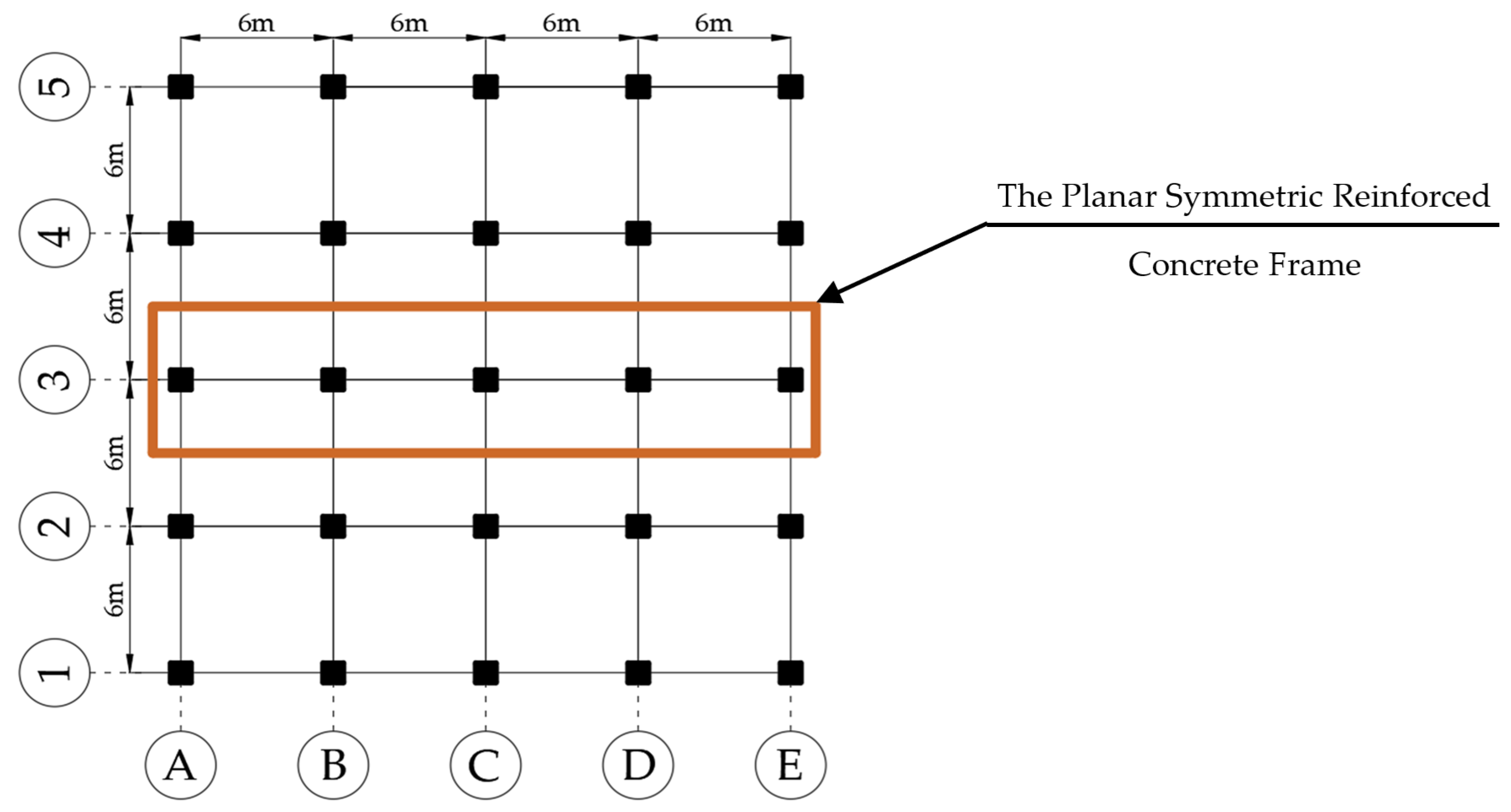
This section details the assumptions adopted for analytical evaluations, performed using fluid viscous dampers (FVDs), in order to develop the supplemental damping-based procedure proposed in this study. The proposed procedure is based on deformation-based methods for the evaluation of seismic performance in newly designed buildings and existing buildings to be retrofitted by using PED systems. In particular, in accordance with the provisions of TBEC 2018 Section 5 [83], ASCE/SEI 41-23 [84] and FEMA 356 [85], the assumptions related to deformation-based approaches were adopted in this study for application to the design of new buildings. As mentioned above, planar type (2-Dimensional) frames were considered in this study, as was previously performed in other studies [22,45,54,55,86]. The schematic plan view of the sample building and its investigated frame is illustrated in Figure 1.
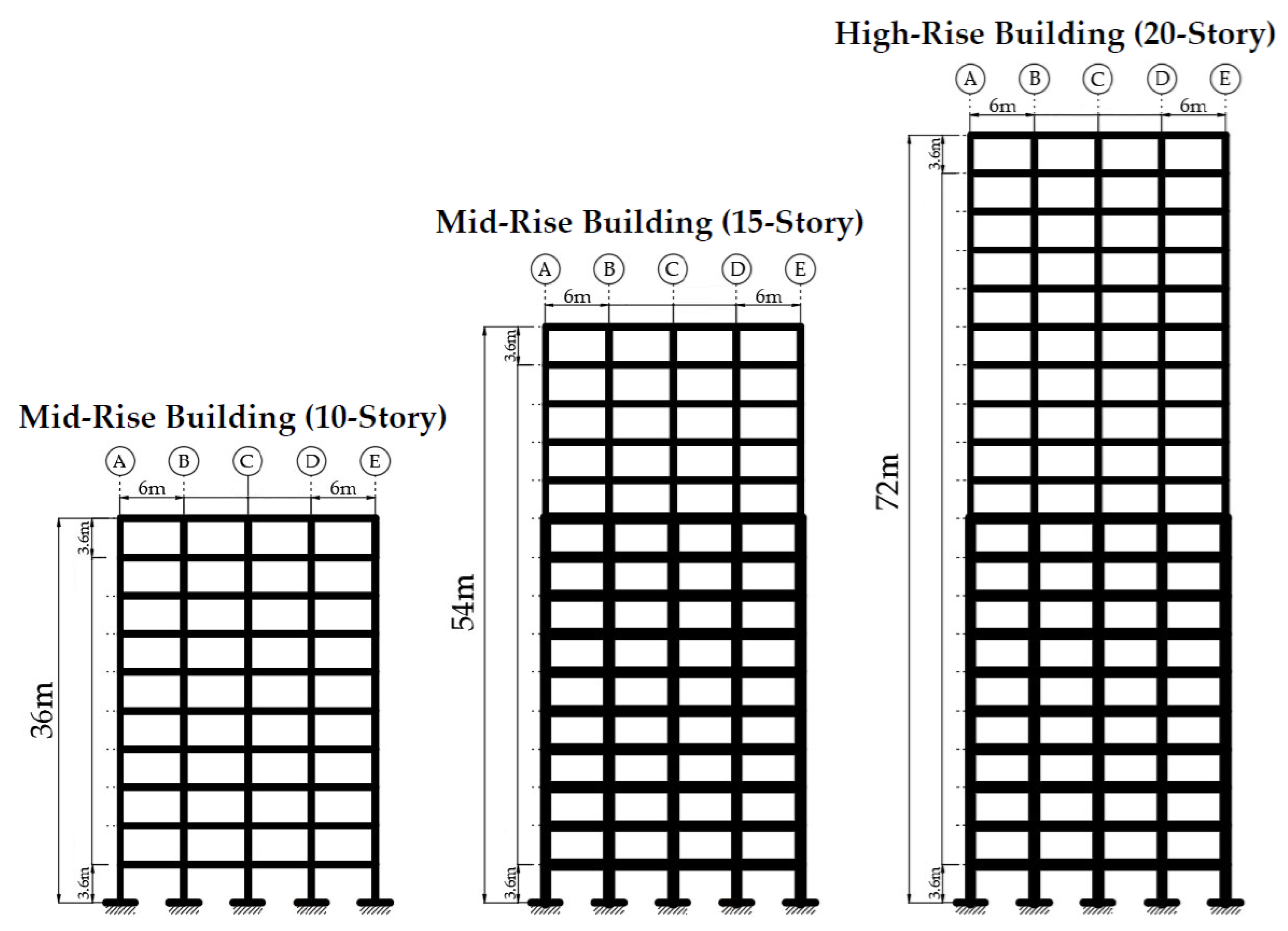
In this study, a total of 22 planar reinforced concrete frames with different reinforced concrete member variations were considered. The planar reinforced concrete frames equipped with PED devices and having different building heights (10, 15, 20-story) were analyzed. The distribution of members within the 10-story planar frames is given in Table 1. The distribution of members of other frames, whose story numbers are 15 and 20, can be seen in Table A1.
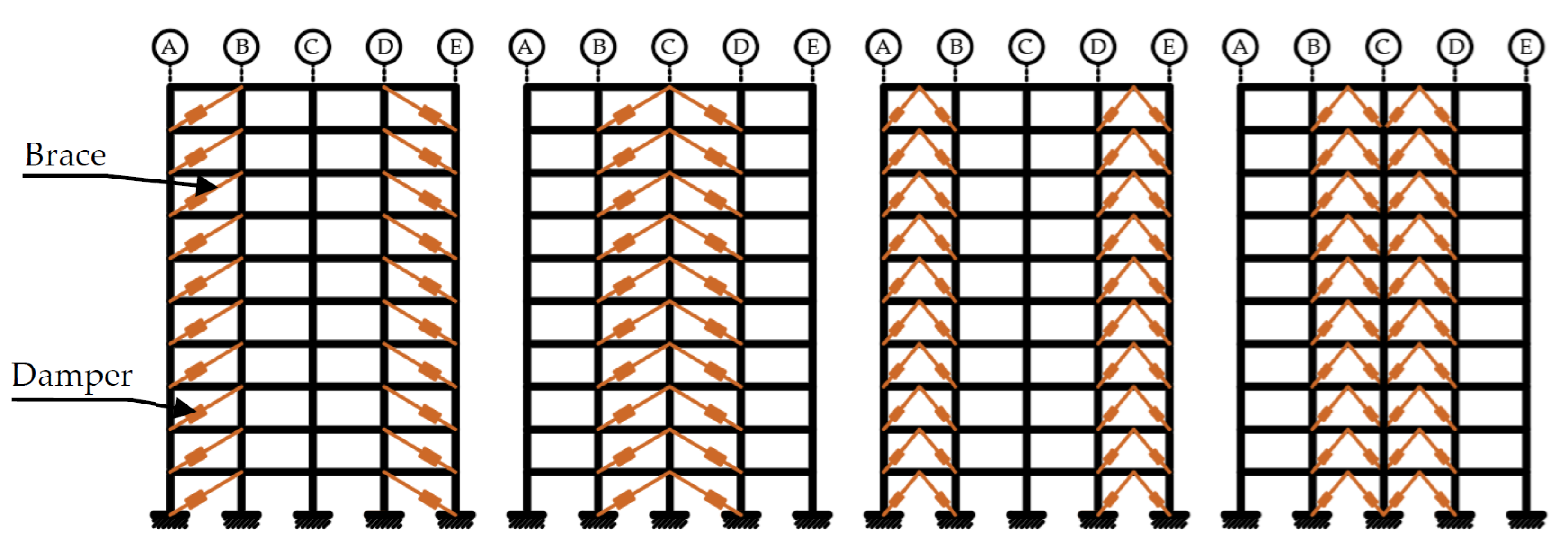
All the investigated frames have the same story heights, which is equal to 3.6 m, and 4 spans whose lengths are 6 m. In the analysis of the frames, reinforced concrete members with different cross-sectional dimensions and reinforcement configurations were utilized. Moreover, for the 15 and 20-story frames, larger cross-sectional members were used in the first 10 stories, whereas the member dimensions were gradually reduced in the upper stories. Regarding the damping systems, different types of FVDs, bracing configurations (diagonal and chevron bracing), and arrangements (external and internal) were considered (Figure 2 and Figure 3).
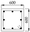
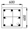
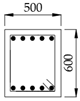
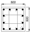
The cross-sectional dimensions and reinforcement details of the reinforced concrete members are presented in Table 2. As an example, the column and beam elements in the first 10 stories of Frame Type 6 were arranged as C3 (600 mm × 600 mm) and B7 (400 mm × 600 mm), respectively.

2.1. Modal Analysis

In the analytical models developed in OpenSees [67], rigid diaphragm behavior was assumed at each floor level. Reinforced concrete sections (confined/unconfined concrete and reinforcement) were modeled using a fiber-based approach, in which the concrete and steel components were represented by individual fibers. The concrete material was defined using the “Concrete02” material model, which is based on the Kent and Park model [87] and incorporates the residual strain and stiffness degradation under cyclic compression rules proposed by Karsan and Jirsa [88], as well as tensile behavior. The cyclic stress–strain behavior of the reinforcing steel was defined using the “uniaxialMaterial (Hysteretic)” model [89]. For the design of structural members, concrete class of C20 and C30, and reinforcement steel type of S420 were assumed. These material properties (characteristics) correspond to concrete with cylinder compressive strengths of 20 MPa and 30 MPa, respectively, and reinforcement steel with the yield strength of 420 MPa.

2.2. Nonlinear Time History Analysis

In this study, nonlinear time history analyses (NTHA) were performed using the OpenSees software [67] by using the “integrator Newmark” command, which is based on the Newmark integration method. The OpenSees platform [67] provides a tangent stiffness-based Rayleigh damping model, and this approach is followed. The deformation-based action ( Q UD ) caused by gravity loads and earthquake forces is given below in accordance with Section 5.2.2 of TBEC 2018 [83].
  Q UD =   D +   L eff +   0.2   S   +   E d H + 0.3   E d V
where D is the dead load of the structure, including the superimposed dead load, Leff is the effective live load defined as Leff = n L (in which n was taken as 0.3), and S is the snow load, E d H represents the horizontal seismic effect, 0.3   E d V represents the vertical seismic effect, taken as 0.2 SDS.
The mean response quantities obtained from multiple nonlinear time-history analyses are adopted as representative indicators of the seismic performance. This averaging procedure reduces record-to-record variability and mitigates record-specific irregular responses; thus, providing a more stable and reliable representation of structural demand, consistent with the recommendations of TBEC 2018 [83] and ASCE/SEI 41-23 [84] for performance-based seismic evaluation using suites of ground motion records.

2.3. Inelastic Behavior of Frame Elements

Concentrated plasticity is one of the most commonly applied approaches for representing the inelastic behavior of structural members in multi-story buildings [90]. Accordingly, the beams and columns were modeled using concentrated plastic (lumped plastic) hinges in the OpenSees [67]. The inelastic behavior of the structural elements was modeled in OpenSees [67] by employing uniaxial bilinear hysteretic material models. By defining the stress–strain relationships of these material models, the P–M–M interaction curves and the moment–rotation relationships that characterize the inelastic behavior of the elements were obtained by using the aforementioned material models.
The behavior within the plastic hinge regions follows the bidirectional hysteretic response defined by the “Hysteretic” command. This hysteretic model is associated with multi-segment idealized backbone relationships that define the strength and deformation bounds of the structural element. In addition, the model incorporates a set of constitutive behavior rules that characterize the hysteretic response between these defined bounds. These rules define the hysteretic characteristics by accounting for several effects such as pinching, stiffness degradation, and other related mechanisms.

Backbone Relationships and Damage of Structural Elements

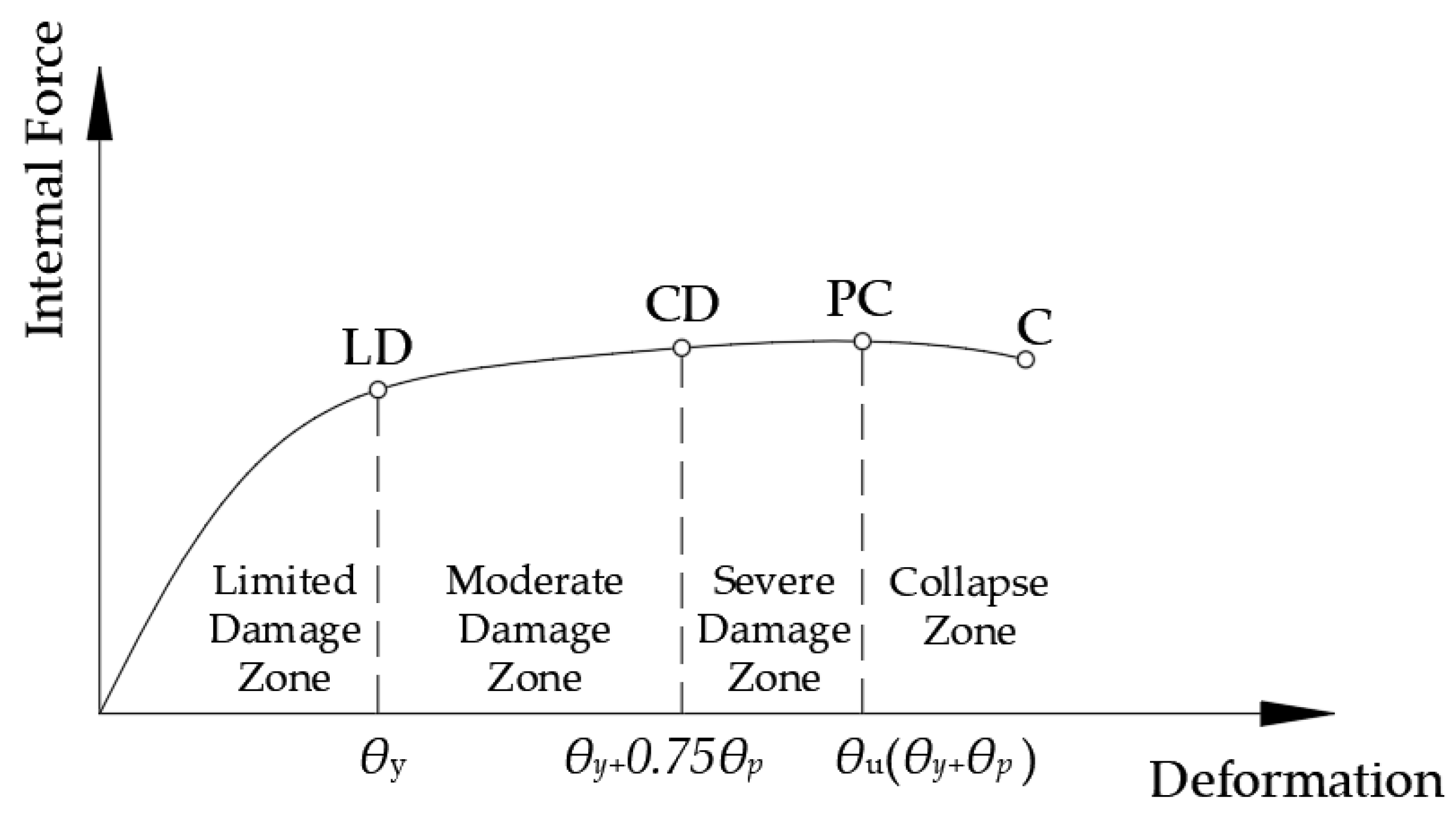
According to the TBEC 2018 [83] provisions, the schematic backbone curve representing the plastic hinge behavior (elastic, plastic, and collapse) is presented in Figure 4. The damage states for reinforced concrete members are defined as Limited Damage (LD), Controlled Damage (CD), and Collapse Prevention (CP). In Figure 4, Point (C) represents the collapse state, where the member’s load-carrying capacity is effectively lost.
The section damage limits adopted in this study were evaluated based on the approaches of TBEC 2018 [83] and Eurocode 8-3 [91], which rely on experimental data and semi-empirical capacity relationships. The Limited Damage (LD) defined in Equation (5.3) of TBEC 2018 is given as follows in terms of rotation:
θ y   =   ϕ y L s 3 +   0.0015 η   ( 1 + 1.5 h L s ) + ϕ y d b f y 8 f c
In this formulation, TBEC 2018 specifies that the coefficient η is taken as 1.0 for beams and columns. The cross-section depth is h, the yield curvature is ϕ y , the shear span is L s , and the reinforcement bar diameter is d b . The concrete compressive strength is represented by f c , and the yield strength of the reinforcement is f y . The maximum allowable plastic rotation for Collapse Prevention (CP), defined in Equation (5.6) of TBEC 2018 [83] and derived from Eurocode 8-3 Equation (A.4), is given as follows:
θ p ( CP )   =   2 3 [ ( ϕ u   ϕ y ) L p ( 1 0.5   L p L s ) +   4.5   ϕ u d b ]
In this formulation, the ultimate curvature at the section end is represented by ϕ u , and the plastic hinge length is L p . The final term in the expression corresponds to the reinforcement slip rotation associated with yield penetration in the post-yield range (up to the collapse prevention state).
Adopting an assumption similar to that made in Section A.3.2.3 of Eurocode 8-3, the plastic rotation limit for the Controlled Damage (CD), θp(CD), is assumed as 75% of the plastic rotation limit defined for the Collapse Prevention (CP), in accordance with Equation (5.7b) of TBEC 2018.

2.4. Seismicity of Region

The reinforced concrete frames are assumed to be located in regions corresponding to Site Class B, C, or D according to TBEC 2018 [83] and FEMA 450 [92] classification. For these site classes, the response spectra corresponding to the DD-2 earthquake level (Design-Based Earthquake with a return period of 475 years) were generated in accordance with the provisions of TBEC 2018 [83], considering the seismicity of the region. The seismic region considered for the selection of ground motion records is located along the North Anatolian Fault Zone in Türkiye. Within this context, the region that was most severely affected by the 1999 Kocaeli earthquake was selected. Spectral acceleration coefficients, which characterize the design spectrum, are taken from the Turkey Earthquake Hazard Maps (TDTH) [93] for 10 randomly selected locations situated approximately 30 km from the North Anatolian Fault Zone. Mean value of spectral coefficients and peak ground acceleration of all considered locations are Ss = 1.0, S1 = 0.3, and PGA = 0.4 g.

Selecting and Scaling Ground Motions

The ground motions used in the nonlinear THA analyses were selected from the 5% damped “flatfile” dataset of the PEER NGA-West2 database [94], considering the following criteria: earthquake magnitude, fault mechanism, source-to-site distance (epicentral distance), and site class. A total of 33 ground motion records were used, covering several values of parameters mentioned above, so that uncertainties due to the nature of the earthquake can be taken into account.
The selecting and scaling method commonly accepted and used in the literature is based on the references [95] and [96], respectively. They proposed a method that determines records with spectral shapes similar to the target spectra by computing the Root-Mean-Square (RMS) difference in their study, published in 2004. Similarly, to satisfy the requirement of matching the target spectra within the relevant period range, the method was revised, and an individual scale factor (α) was determined for each record that minimizes the root-mean-square difference between the scaled geometric-mean spectra of the real record and the target spectra as given in Equation (4). In this way, by scaling the ground-motion record, an appropriate match with the target response spectra can be achieved within the desired period interval.
D RMS = 1 k j + 1 i = j k ( α   Sa R ( T i ) Sa T ( T i ) ) 2
In the above equation, Sa R ( T i ) is the spectral acceleration of the ground motion record at period T i , while Sa T ( T i ) represents the spectral acceleration of the target spectra at the same period. The parameters T j and T k define the period range where the spectral matching is performed.
The scaling procedure does not alter the frequency content of the ground-motion record; rather, the recorded motion is uniformly scaled up or down to catch the best match with the target spectra within the period range of interest. When multiple ground-motion time histories are considered, each record may be scaled individually using the same procedure, or the average of the generated spectra can be best-fitted to the target spectra [97].
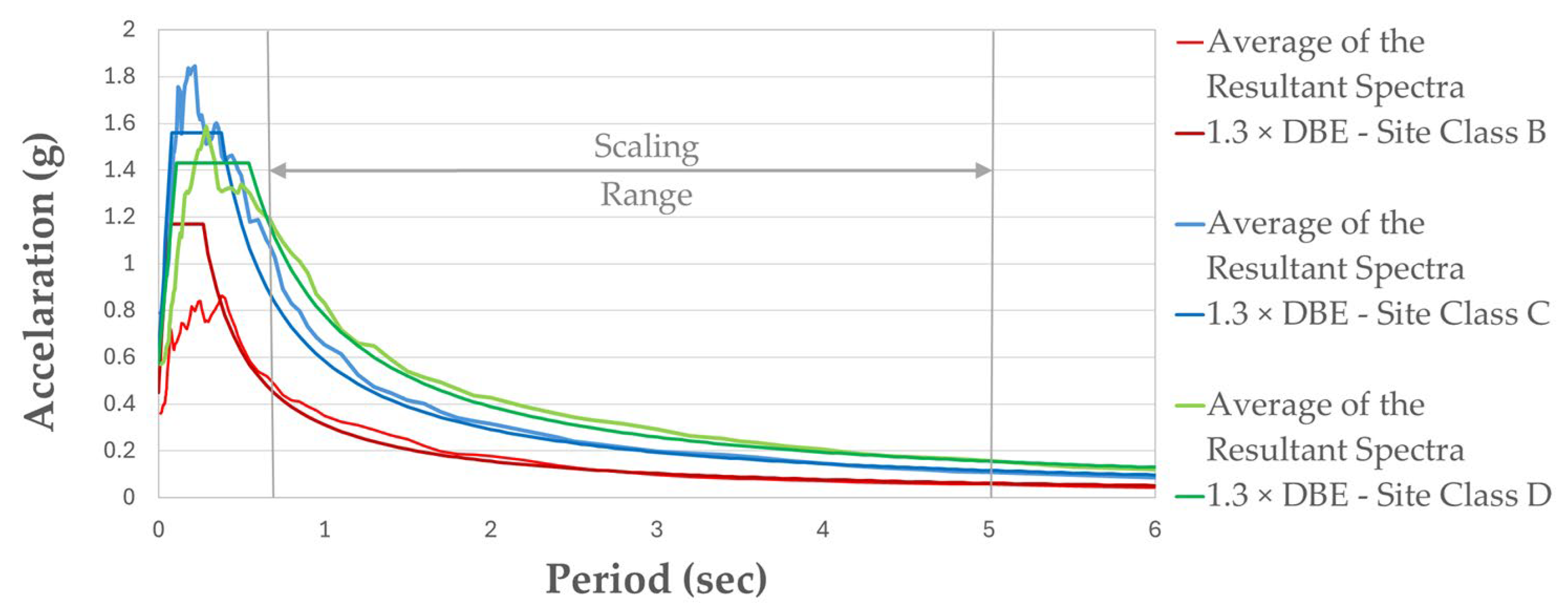
In this study, following the provisions of TBEC 2018 [83], the amplitudes of the ground motion components were scaled such that the average of the resultant spectra from all records satisfies the requirement that the ratio of their amplitudes to those of the design spectra within the 0.2 T to 1.5 T period range shall not be less than 1.3. Accordingly, the parameters of Tj and Tk defined above correspond to 0.2 T and 1.5 T, respectively. T shows the fundamental period of the structure. The properties of the selected far-fault ground motions (earthquake name, year, station name, record sequence number, magnitudes, and epicentral distance) and scale factors for Site Class B are presented in Table 3. Table A2 and Table A3 give the same information for the Site Class C and Site Class D, respectively. The average response spectra of the scaled ground motion records are illustrated in Figure 5.

2.5. Target Performance

In international seismic design standards, it is required that structures have an acceptably low probability of collapse under the rare ground-motion effects corresponding to the Maximum Considered Earthquake (MCE) level. This performance objective implies that the structure should maintain its vertical stability and avoid global collapse, even if it experiences severe and irreparable damage. Additionally, under the Design Basis Earthquake (DBE) ground-motion level, life-threatening damage arising from the failure of structural components must be prevented [85,98,99].
In this study, the Controlled Damage (structural damage without threatening “Life Safety”) performance level is targeted at the DBE level. This approach is consistent with the criteria specified in TBEC 2018 [83], while allowing controlled inelastic behavior and thereby ensuring structural integrity without imposing unreasonably high design or retrofit demands. Accordingly, this performance objective provides a balanced approach between safety and economic feasibility while providing life safety.

3. FVD Design and Determination of Supplemental Damping Ratio

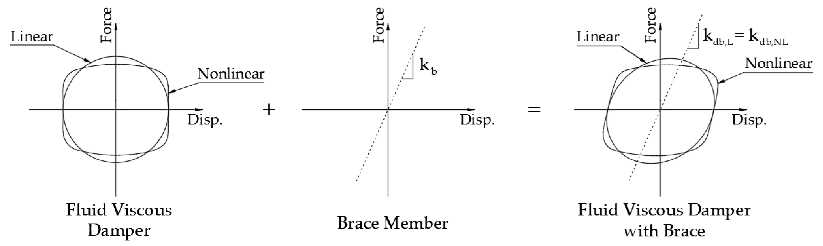
PED devices have specific working principles, characteristic features, and hysteretic behavior models governed by these characteristics. Considering the commonly adopted force–displacement behavior that represents the hysteretic response of different damper types, this section presents the procedures for estimating the supplemental damping ratio for FVDs (Figure 6). The use of FVD among PED systems has increased due to their ability to enhance seismic performance through energy dissipation and their capability to increase damping without significantly affecting the structural stiffness characteristics. FVDs can be implemented in both new structures and in the retrofit of existing structures. According to [32], the damper force for FVDs, as velocity-dependent energy dissipation devices, can be expressed as follows:
F FVD   =   C FVD   | u ˙ | a   sgn ( u ) ˙
Herein, FFVD is the effective damper force, u is the relative displacement between the two ends of the damper, CFVD represents the damping coefficient of the device, u ˙ is the relative velocity between the damper ends, and a is the exponential constant characterizing the behavior of the damper. For linear FVDs, a is assumed to be 1, whereas for nonlinear FVDs, 0.3 is adopted.
Given that the influence of linear and nonlinear fluid viscous dampers on structural stiffness is negligibly small, the stiffness of the structure is assumed unchanged [20,52]. In this context, the stiffness of linear and nonlinear fluid viscous damper is kd, and their stiffness when used in combination with bracing members, represented as kdb,L, and kdb,NL, and the subscript “b” indicates the braced configuration of the damper.
In the structural analyses conducted within the scope of this study, the properties of the damping system incorporating nonlinear fluid viscous dampers are based on the Maxwell model of viscoelasticity, which idealizes an exponential viscous damper connected in series with a linear spring, commonly referred to as the Maxwell stiffness.

3.1. Design of Fluid Viscous Dampers

In the general strategy, for buildings that are retrofitted or designed using dampers, the damper characteristics and the corresponding supplemental damping ratios are determined in accordance with the target seismic performance level. However, in this study, appropriate damper properties are also investigated by performing analyses that consider all relevant performance levels. The design assumptions and the characteristics of the dampers used in the planar frames are given below.
In summary, the behavior of the fluid viscous damper depends on the damping coefficient (CFVD), velocity ( u ˙ ) and exponent constant (a). At the initial phase of the damper design methodology, the performance level of the structure is determined without incorporating dampers. The seismic performance analyses are performed using various damping coefficient values for a specific damping force capacity (FFVD) obtained from the manufacturer’s catalog [100]. Subsequently, the analyses are repeated for damping coefficient values corresponding to different damping force capacities. As a result of these analyses, supplemental damping ratios are calculated. Accordingly, the performance levels for the structure can be determined based on the supplemental damping ratio, provided that the stroke demands obtained from the analyses remain within the limit values. Table 4 summarizes the stroke limits, FFVD, and CFVD values used in the analyzed models.
In the OpenSees [67], FVDs were modeled using the “ViscousDamper” uniaxial material model to represent their velocity-dependent nonlinear behavior. This material was assigned to a “twoNodeLink” element connecting the diagonal nodes. Accordingly, the deformation across the damper is specified only in the axial direction to accurately simulate the piston motion of the damper. In addition, since the “twoNodeLink” element does not contribute to Rayleigh damping by default, the energy dissipation is governed solely by the FVD parameters.

3.2. Supplemental Damping Ratio Assumptions for FVDs

The supplemental damping coefficient should be defined such that the energy dissipated by the idealized damper is equivalent to the total energy dissipated by all damping mechanisms in the structure. This idealization is referred to as “equivalent viscous damping. The equivalent viscous damping ratio can be obtained by equating the energy dissipated per cycle of a periodic excitation to the corresponding value of viscous damping. When the system response is most sensitive to damping (ω = ωn), this relationship is given by Chopra [101] as follows:
ξ eq   =   E D 4 π E S  
where ED and ES are the dissipated energy and the strain energy of the system, respectively. In determining the supplemental damping ratio contributed by FVDs to the structural system, the characteristic properties of the device will be employed to perform the necessary mathematical transformations on Equation (6). Accordingly, the energy dissipated by the damping system (ED) and the strain energy of the structural system (ES) will be determined using the idealized hysteretic behavior model of the damper. Table 5 summarizes the general expressions of the equations for the equivalent damping ratio provided by FVDs. The first expression represents the general equivalent damping ratio defined for SDOF systems equipped with FVDs. The second and third expressions define the equivalent damping ratio of the structure for multi-degree-of-freedom (MDOF) systems incorporating linear and nonlinear braced FVD systems, respectively. Based on the nonlinear THA, the data extracted from the force–displacement responses of the dampers used in the structure were examined, and a verification check was performed using the equations provided in Table 5.
Here, in the fundamental mode, the relative displacement between the two ends of the damper is   u d 0 , and the relative displacement between the two ends of the braced damper is   u db 0 . The inclination angle of the braced damper is θ, the effective story mass is m, the story displacement in the fundamental mode is   u K , the natural vibration period is T, and the circular frequency is ω. N represent the number of identical damped bracing members in a story having the same CFVD value, λ is a parameter computed by the expression 2 2   +   a Γ 2   ( 1   +   a / 2 )   Γ ( 2   +   a ) and A is the modal roof displacement normalized to unit value. In the general expressions, the subscript “j” indicates the j-th damper device, while the subscript “i” represents the i-th story.
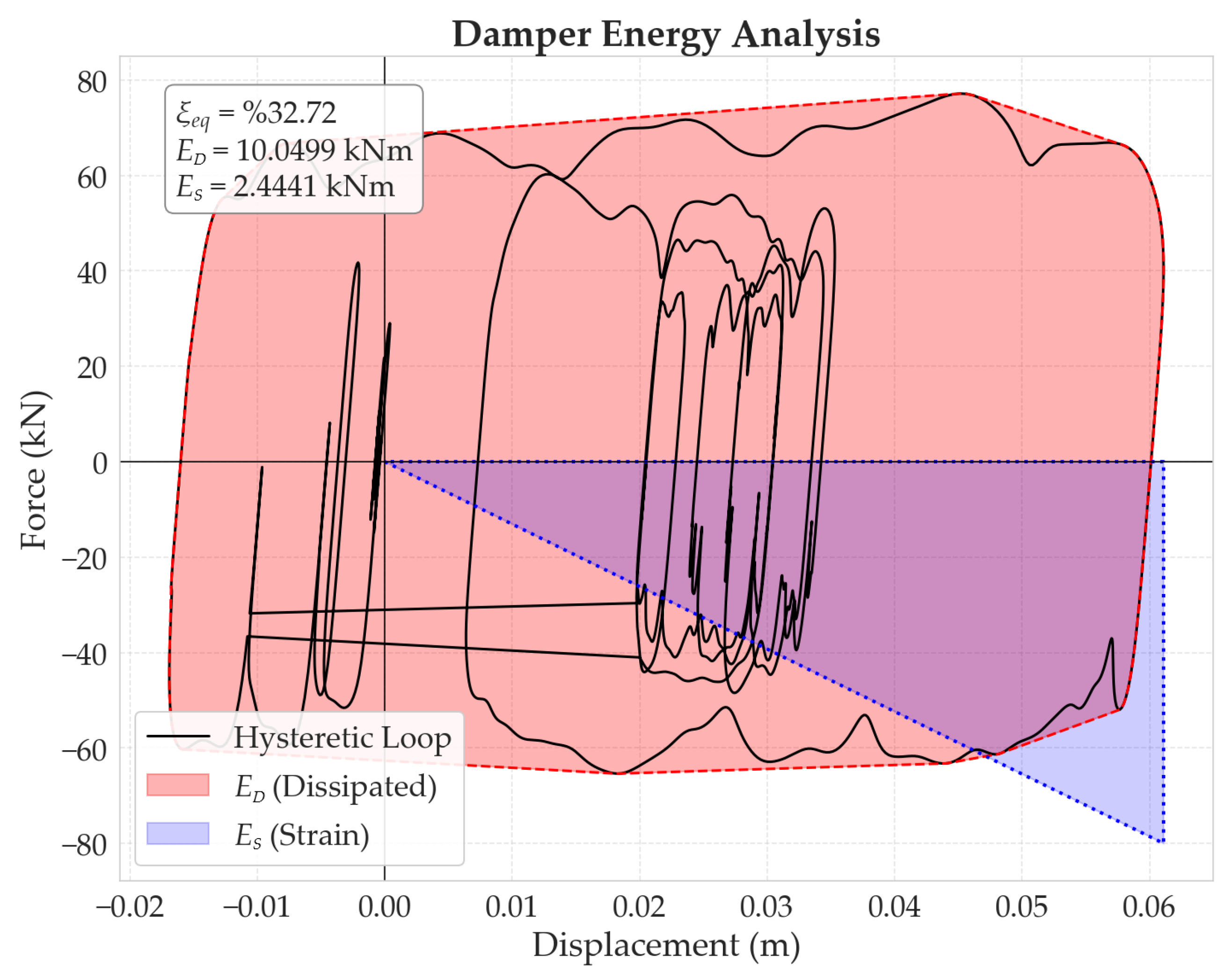
For each frame type examined in this study, the equivalent viscous damping ratio was determined by averaging the areas enclosed by the hysteretic loops of all dampers used in the analyses. Specifically, the areas enclosed by the hysteretic loops were calculated using a post-processing algorithm prepared in Python software (version 3.12) [102] using the coordinate data of the hysteretic curves obtained from OpenSees software [67]. The supplemental damping ratio of the structure was obtained by subtracting the assumed 5% inherent damping ratio of reinforced concrete structures from the damping ratio calculated from the analysis results, as explained above. Figure 7 presents an example of the supplemental damping ratio calculation for a damper illustrated in graphical form. The hysteretic loop, the dissipated energy by a damper (ED), and strain energy (ES) obtained for Frame Configuration No 1 with external diagonal FVDs under the effect of the Imperial Valley earthquake, 1979.

4. Proposed Design and Retrofitting Methodology

In the design and retrofitting of structures equipped with PED systems (PEDS), several approaches are used either to evaluate structural performance or to design dampers in accordance with a target performance level [26,30,31,64,77]. In these approaches, the results obtained from equivalent single-degree-of-freedom (SDOF) systems are commonly adapted to represent multi-degree-of-freedom (MDOF) systems based on assumptions made for key parameters, such as ductility associated with elastoplastic behavior and the effective natural vibration period, which change according to the stiffness contribution of the damper devices. Although these approaches are internally consistent, the characteristics of the dampers are strongly dependent on the properties of the structural systems. In this context, the structural behavior characteristics of MDOF systems may vary significantly depending on variables such as the contribution of member dimensions or structural configuration to elastic behavior, as well as the role of reinforcement detailing in governing nonlinear behavior. Consequently, they inevitably involve preliminary assumptions in the design process despite their consistency.
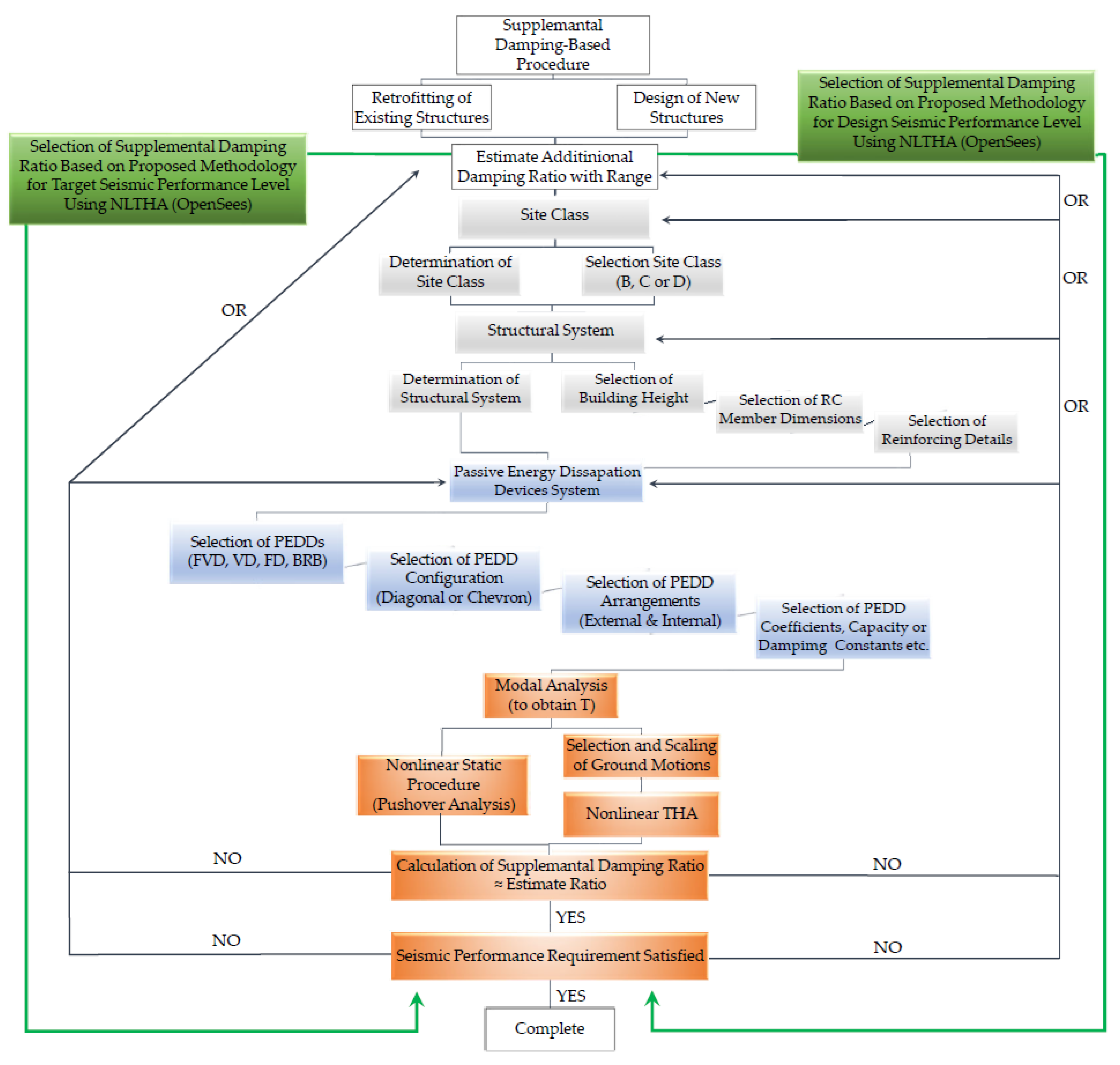
The proposed procedure comprises two main components. The first part is developed to establish a relationship between the target seismic performance levels and the supplemental damping ratio (SDR) by explicitly accounting for the interaction between the structure and the damping system, rather than prespecifying damping or structural parameters. The flowchart of the procedure is shown in Figure 8. The procedure incorporates key parameters (device characteristics, configuration and arrangement of devices, structural member dimensions, building height, and reinforcement detailing, as well as Site Class) of dampers and structure, which are effective on the design and optimization of dampers. As shown in Figure 8, in addition to structural parameters, different site classes, PED device types, PED configuration and arrangement, and PED characteristics can be considered through this procedure. The first part of the procedure is shown using gray and blue colors in a flowchart. The last step of the flowchart comprises the performance verification of the structural system with PED devices, as shown in orange in the flowchart.
Consequently, the proposed seismic design and retrofitting procedure can be regarded as an alternative to force, displacement, and energy-based earthquake design procedures, as it explicitly accounts for the effects of supplemental damping on seismic performance and the key parameters governing the interaction between the structure and the damper system.

4.1. Description of the Flowchart

In this section, the proposed supplemental damping-based method for RC planar frame structures equipped with PEDS is summarized. The flowchart illustrating the proposed method for the design of new buildings and the retrofitting of existing buildings is presented in Figure 8.
  • Estimation of the supplemental equivalent damping ratio. To simplify the process and improve the efficiency of PEDS optimization, it is recommended that the supplemental damping ratio be selected within a specific range. From an economic perspective, a range consisting of lower values (10–25%) should be selected, whereas for a better performance state (for Limited Damage), a range consisting of higher values (25–40%) is recommended.
  • Determination of the site class.
  • Identification of the structural system.
  • Selection of the PEDD type, PEDD configuration, PEDD arrangement, and PEDD damping constants or coefficients, capacities, etc.
  • Perform elastic modal analysis of the structure with PEDS to obtain vibration modes and periods.
  • Selection of ground motions. The selected ground motions are scaled to the target design spectra based on seismic hazard levels defined by seismic codes and the fundamental period of the structure.
  • Analyze the planar RC frame using (NTHA) or nonlinear static procedure (pushover analysis).
  • Calculation of the supplemental damping ratio (see Section 3.1). If the calculated supplemental damping ratio matches the initially estimated value, proceed to the next step. If consistency is not achieved, for existing structures, revise the PEDS properties starting from step 4 and repeat the procedure, or change the initially estimated supplemental damping ratio. For new buildings, in addition to the aforementioned revisions, the structural system type or site class may be changed.
  • Verify the seismic performance requirements. If the performance requirements/criteria of the frame system are satisfied, the retrofitting of existing frames or the design of new structures is considered complete. If the seismic performance requirements are not satisfied, increase the initial damping ratio.

4.2. Proposed Graphical Approach

As stated above, in damper optimization approaches, when the number, configuration, or characteristic properties of the dampers are modified during the design process, the initial assumptions must be revised accordingly. This situation leads to changes in the behavior of the structural system with damping, thereby causing multiple parameters to be affected simultaneously. However, in damper optimization studies and engineering practice, initial assumptions are generally not updated despite these changes. Consequently, these optimization approaches, which require iterative analyses, are more or less unrealistic. Therefore, based on the proposed procedure, a non-iterative and practical approach has been developed that analytically establishes the relationship between the supplemental damping ratio and the seismic performance of the structure by utilizing the governing key parameters. For the development of these approaches, 5808 nonlinear time-history analyses were conducted in OpenSees, using 33 scaled ground motion records corresponding to 3 site classes, 22 planar reinforced concrete frames, and 16 fluid viscous damper systems. This approach is used as follows: the frame configuration equipped with a damping system is selected, and the corresponding supplemental damping ratio and target seismic performance level are then directly determined on the graph. Figure 9 shows the proposed graphical approach of 15-story frames for Site Class C.

5. Analysis Results and Discussion

Results of the NTHA, which were performed for 10-story planar frame systems using 33 scaled ground motion records, 11 for each site class, are given in this section. The mean values obtained from these analyses for the base shear, maximum roof displacement, and supplemental damping ratio are presented for different damper configurations. The analysis results for the 15 and 20-story structures are provided in Appendix A.
In Section 5.4, the structural performance results, corresponding to different damping system configurations, are presented separately for each ground-motion record for frames located on the Site Class C and D, since the structures investigated for the Site Class B generally exhibit elastic behavior under design-based earthquakes. In Section 5.5, the graphs illustrating the relationship between the supplemental damping ratio and the structural performance levels for different site classes are presented in accordance with the proposed approach.

5.1. Base Reaction

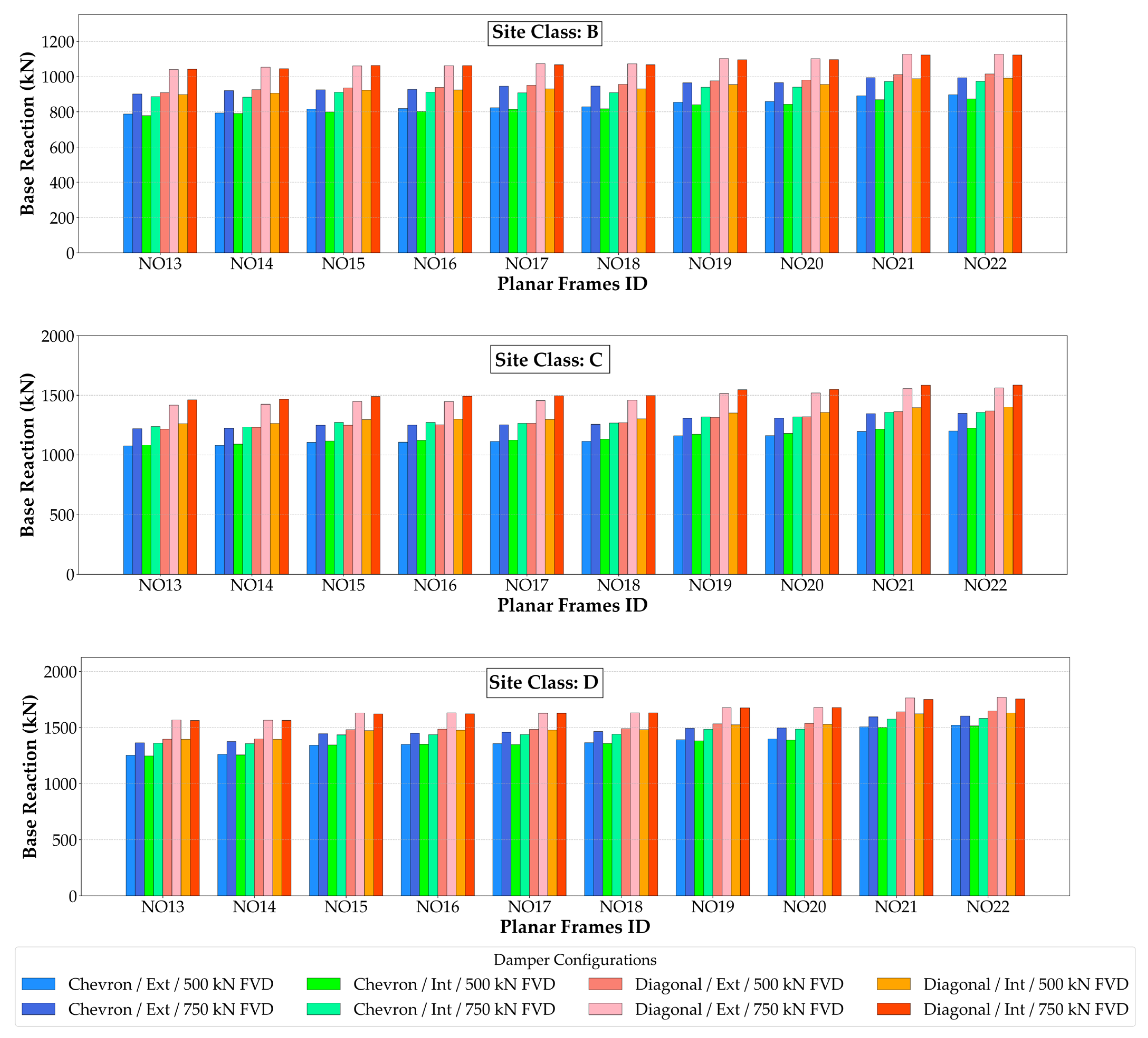
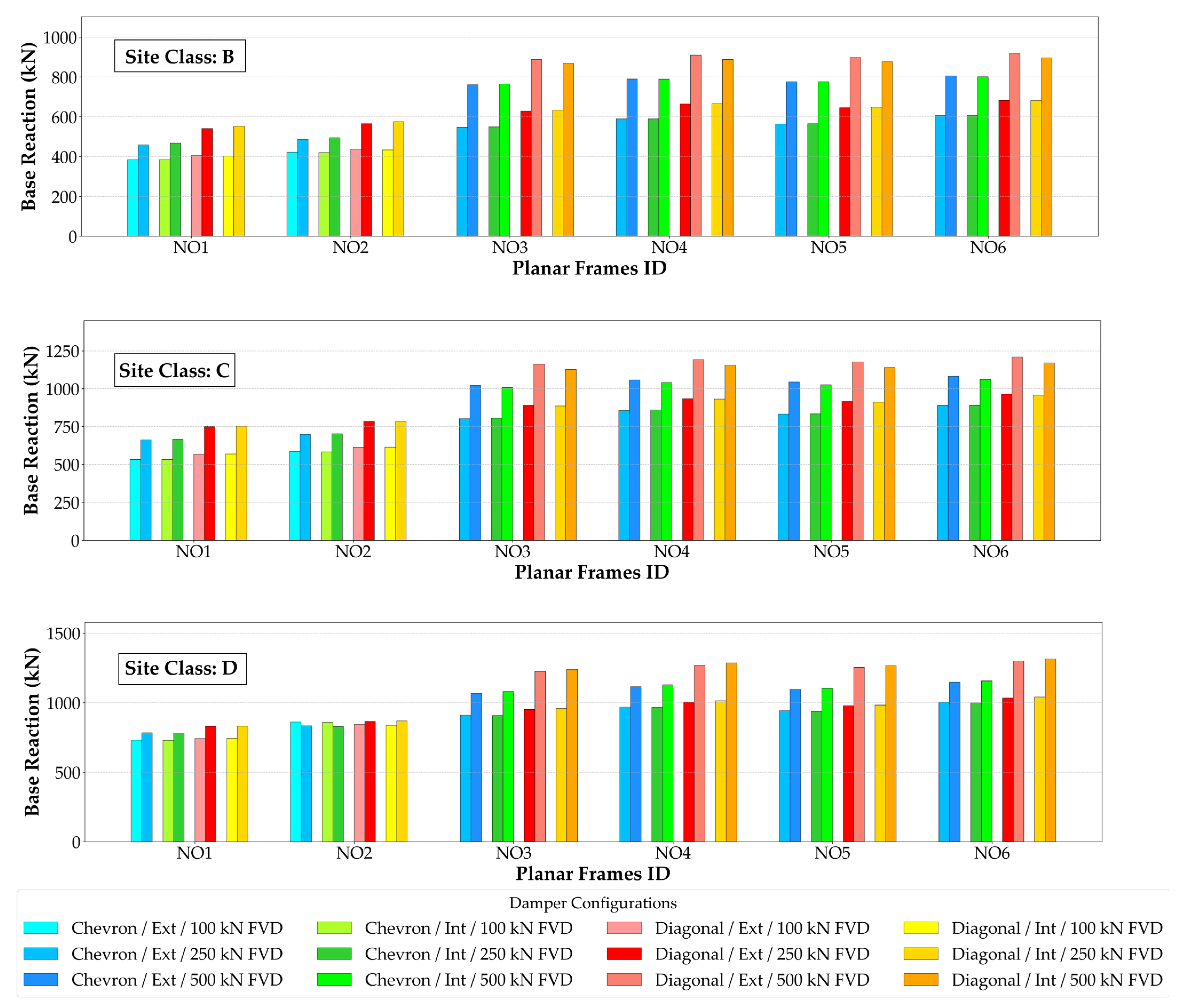
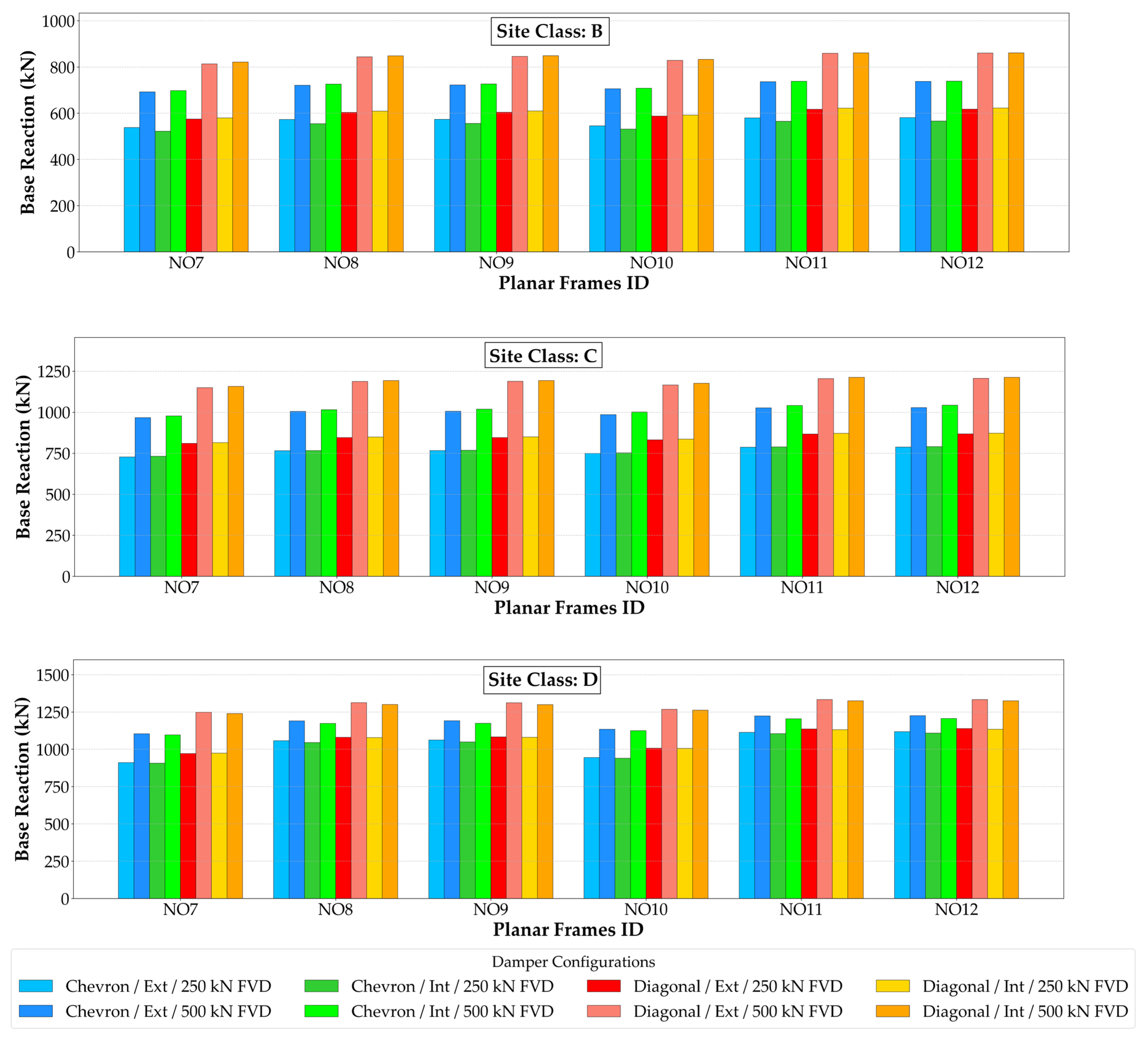
The base reactions of the planar frame systems with different damping system configurations at the DBE level are shown in Figure 10 and are provided as part of general consistency checks in the analyses. This figure summarizes the results obtained for six different 10-story planar frame configurations (No 1–6). For Frame Configuration No 1 and 2 and No 3–6, which have similar column cross-sectional properties within each group (see Table 2), the base reaction values obtained from the analyses are also similar, as it is expected.
For all 10-story frame configurations, diagonal damper configurations consistently result in higher base shear demands than in chevron configurations, with an increase of approximately 15–30%. This response is primarily due to the direct transformation of interstory drift into axial deformation of the diagonal dampers, which leads to an increase in the lateral stiffness of the structural system and consequently the base shear demand. In the case of using a chevron damper, a considerable fraction of the inter-story displacement is taken up by local bending deformations of the beam and vertical force redistribution of the chevron system. Thus, the transformation of the lateral displacement to axial damper deformation is less direct compared to diagonal configurations, causing a reduction in effective lateral stiffness and base shear demand.
Across all frame configurations, frames located on Site Class B exhibit the lowest base reaction demands, being approximately 15–25% lower than those observed for Site Class C and 25–40% lower than those corresponding to Site Class D, based on the response spectra presented in Figure 5. As an illustrative example, for Frame Configuration No 6 equipped with internal diagonal-type FVDs with a rated force of 500 kN, the base reaction is approximately 1315 kN for Site Class D, compared to about 1170 kN and 880 kN for Site Classes C and B, respectively. Figure A1 and Figure A2 present the corresponding results for the 15 and 20-story frames, respectively.

5.2. Roof Displacement Response and Effectiveness of Damping System

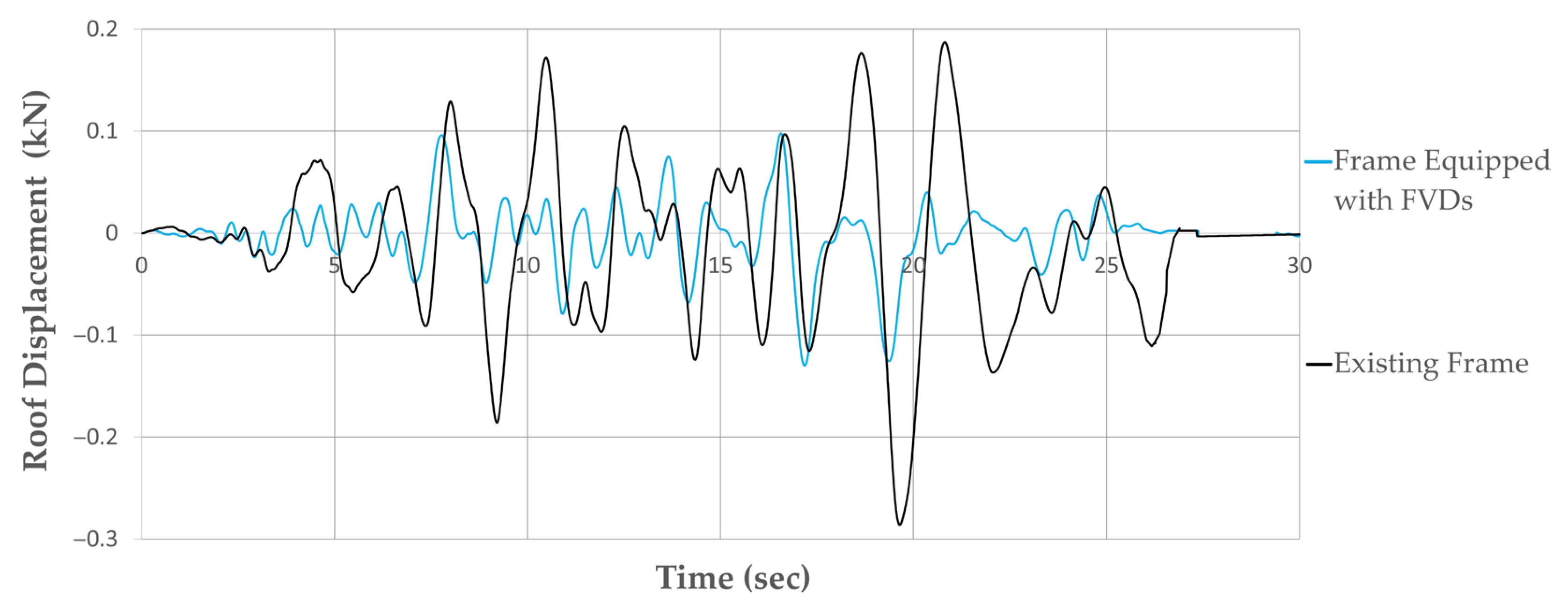
Roof displacement response can provide a basis for evaluating the effectiveness of damping systems. For this purpose, a representative time-history response is first presented to illustrate the influence of FVD. In Figure 11, the roof displacement response corresponds to Frame Configuration No 1 equipped with internal chevron-type FVDs (rated force 250 kN) under the Chuetsu-oki earthquake record (2007) for Site Class C.
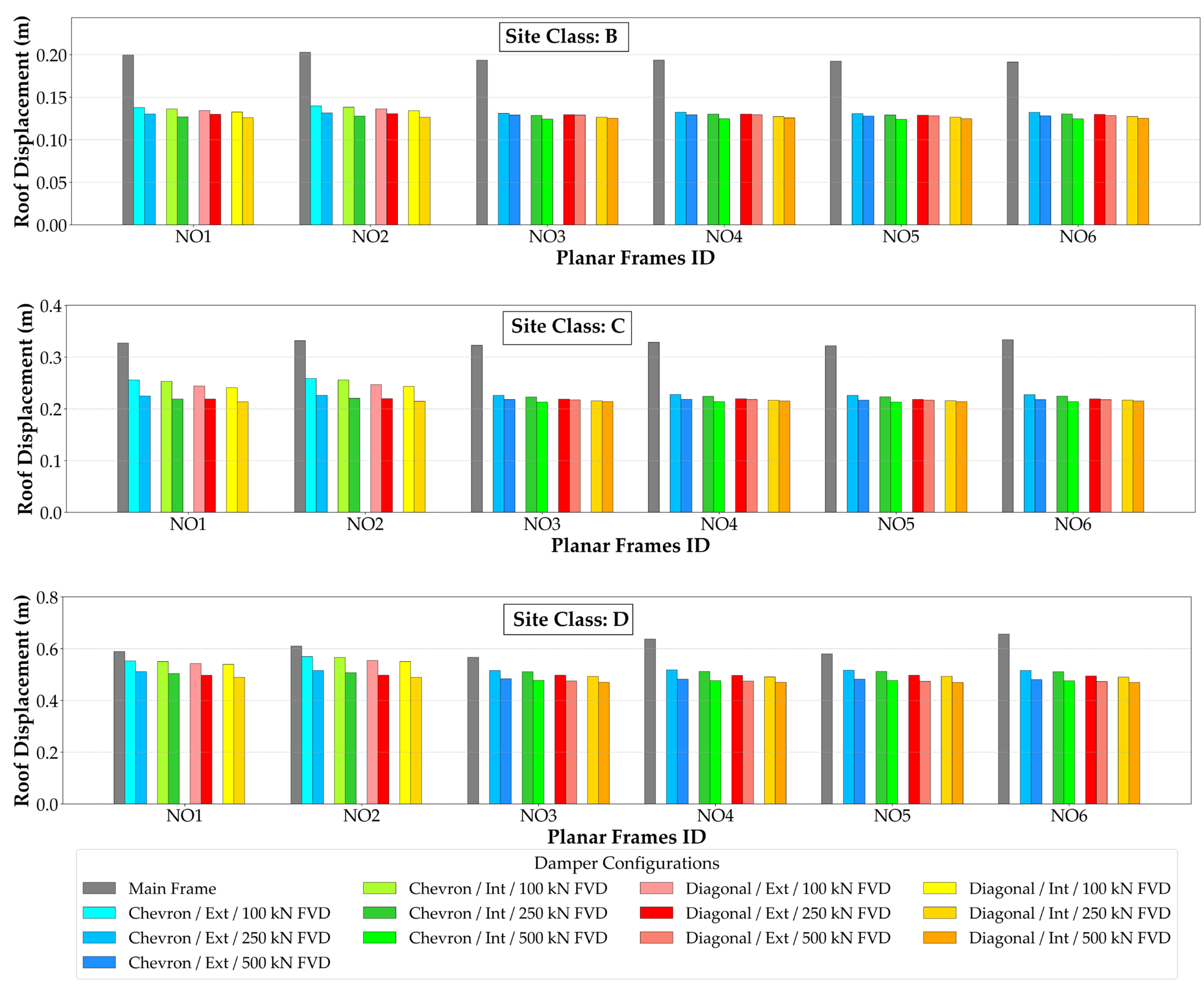
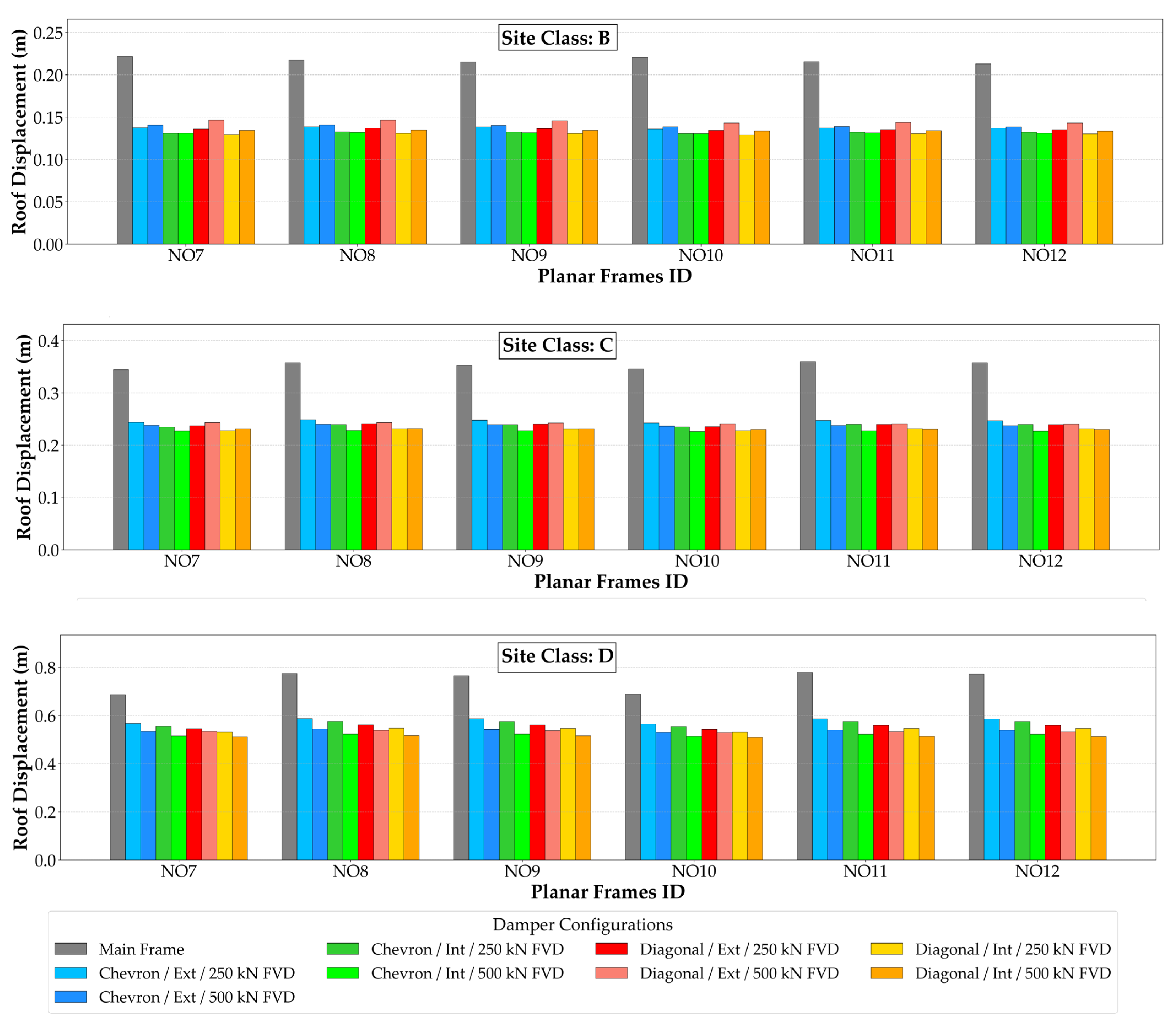
The roof displacement of the planar frame systems with various damping system configurations at the DBE level is shown in Figure 12. This figure summarizes the results obtained for six different 10-story planar frame configurations (No 1–6). The main frame and twelve different FVD system configurations are considered to enable a direct comparison of the roof displacement demands and the effectiveness of the damping systems. The results are examined with reference to Table 6.
The use of viscous fluid dampers results in roof displacement reductions ranging from approximately 14% to 37%, depending on the planar frame configuration and site class. Frame Configuration (FC) No 6 exhibits the highest reduction ratios and roof displacement reductions of approximately 25–28% for Site Class B, 33–37% for Site Class C and 23–27% for Site Class D. The results also reveal a clear dependence on site class, with greater roof displacement reductions achieved for Site Classes C and B compared to Site Class D, reflecting the influence of soil conditions on damper effectiveness. In addition, the consistently higher reduction ratios observed for Frame Configuration No. 6 indicate a more effective interaction between the damper system and the structural response when the primary structural members exhibit ductile characteristics, enabling a more efficient transfer of deformation demand to the dampers.
A more detailed examination reveals that FC No 4 and No 6, which have the same column cross-sectional areas within the 10-story group (see Table 2 for member properties), the base reaction values obtained from the analyses are also similar. However, for FC No 6, when the structural members (see Table 2 for the C3 column and B7 beam properties) exhibit slightly improved ductile behavior, the damper system shows a limited increase in effectiveness, resulting in additional reductions in roof displacement.
In contrast, comparatively lower reduction levels are observed for FC No 1 and FC No 3, particularly for Site Class D, where roof displacement reductions remain within the range of approximately 14–23%, indicating that the damper system is not compatible with the main structural frame.
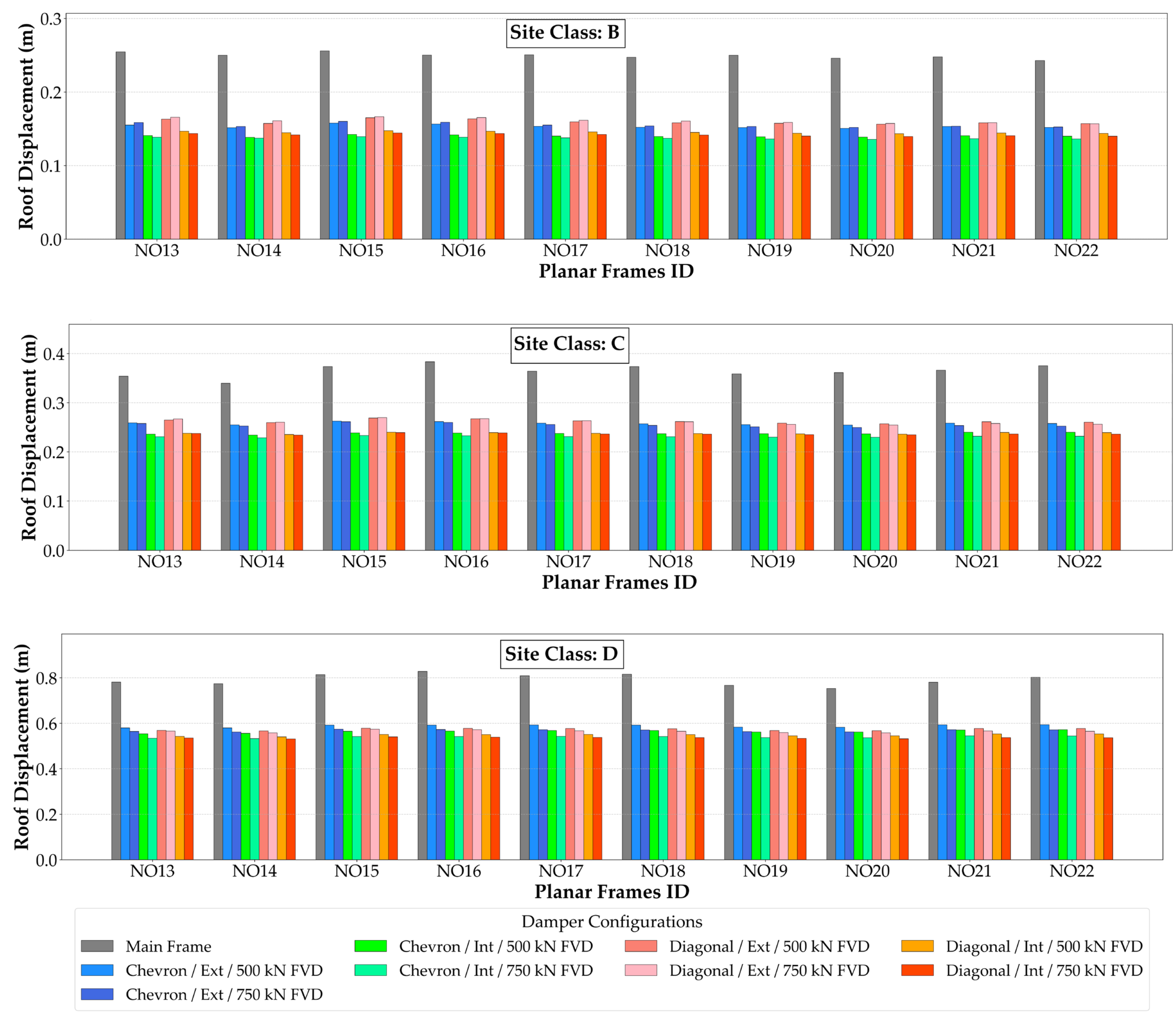
Overall, for all 10-story planar frame configurations, the largest roof displacement reductions are generally observed for Site Class C, followed by Site Class B, while comparatively lower reductions are obtained for Site Class D. Additionally, frames located on Site Class B exhibit lower roof displacement demands, as expected based on the response spectra presented in Figure 5. The corresponding results for the 15 and 20-story frames are presented in Figure A3 and Figure A4, respectively.

5.3. Supplemental Damping Ratio

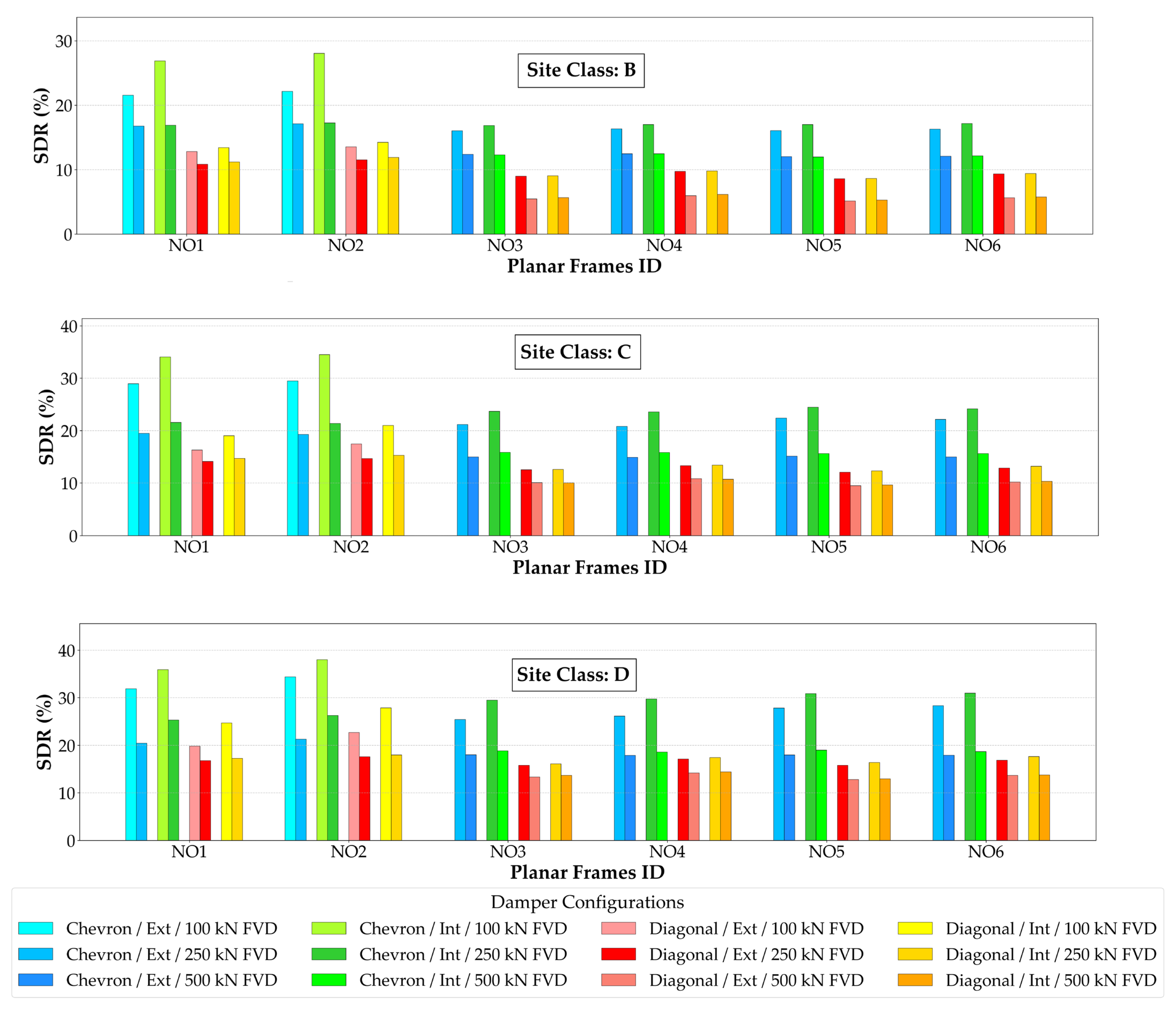
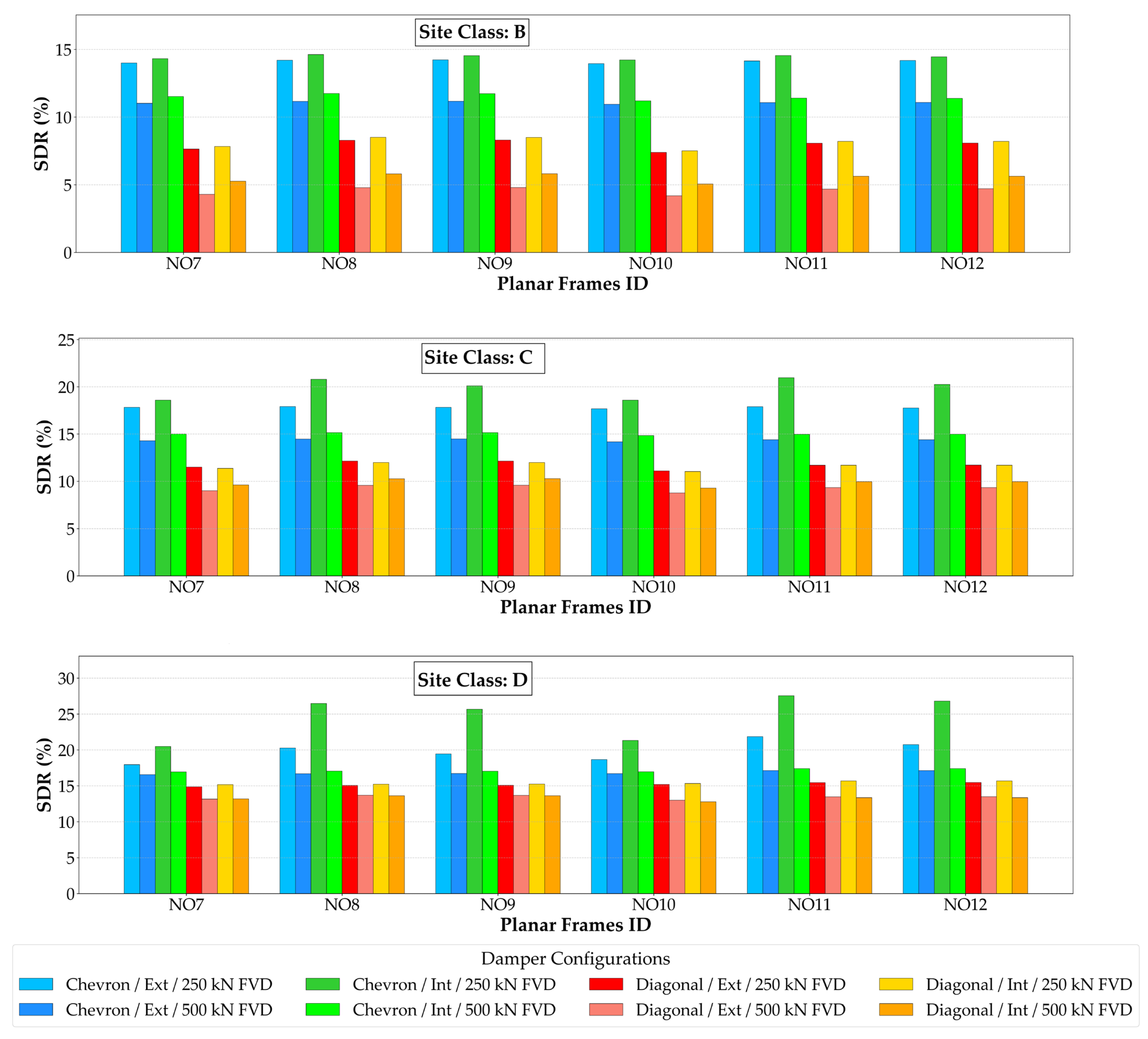
The supplemental damping ratios of the planar frame systems with different damping system configurations at the DBE level are shown in Figure 13 and are provided as part of general consistency checks in the analyses. This figure summarizes the results obtained for six different 10-story planar frame configurations (No 1–6).
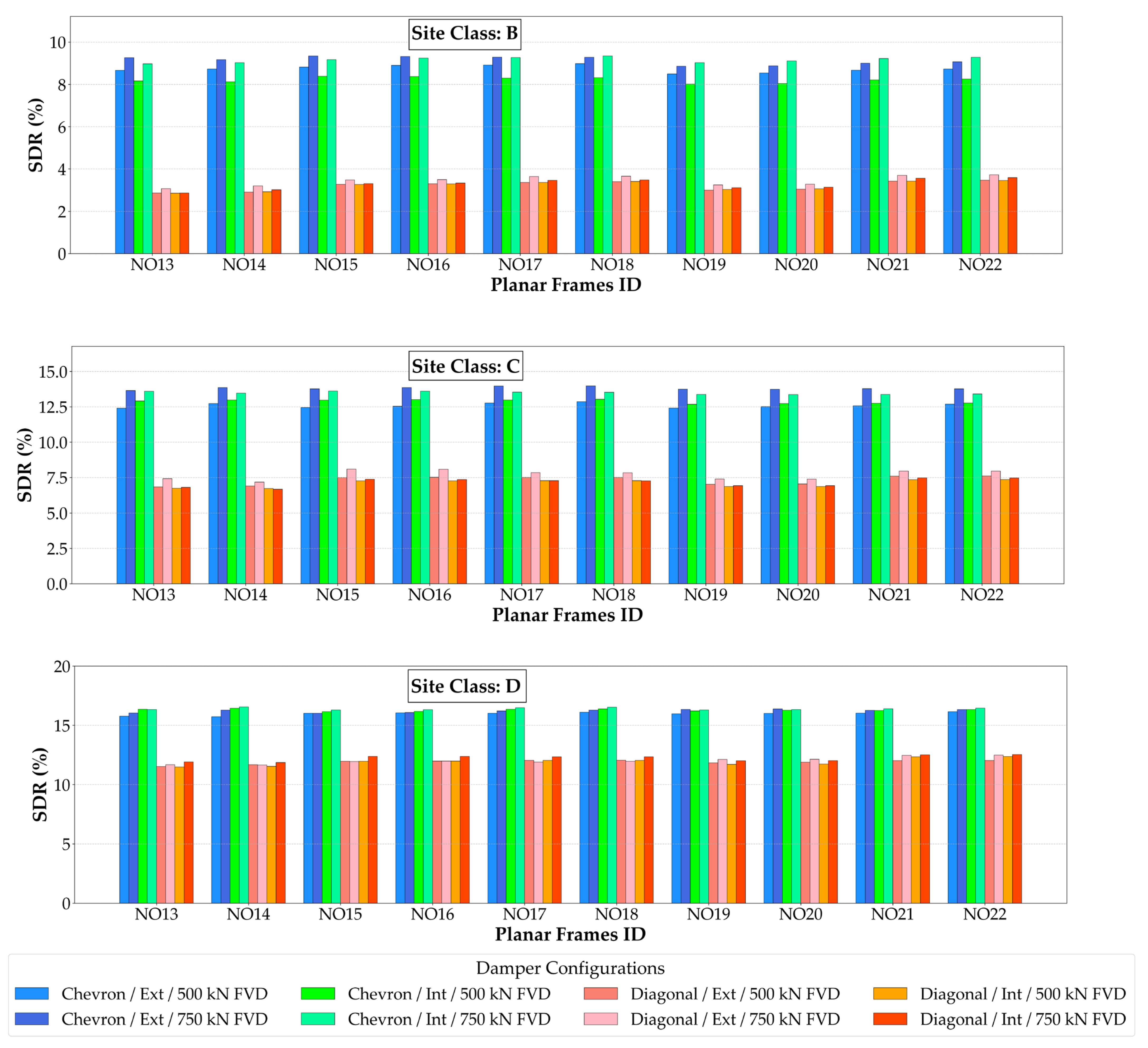
For planar Frame Configuration (FC) No 1 and 2, slender columns (see Table 2 for C1 column properties) exhibit low lateral stiffness and high displacement demand (Figure 12), which leads to increased damper activation and higher supplemental damping ratios, typically ranging from approximately 20% to 35%, depending on the damper configuration and site class. In contrast, for FC No 3–6, lower displacement demands are observed (Figure 12), which lead to reduced damper activation and lower supplemental damping ratios, generally remaining within the range of approximately 10% to 25%.
Chevron damper configurations consistently provide higher supplemental damping than diagonal damper configurations for all 10-story planar frames, typically by approximately 4–14 percentage ratios, depending on the frame configuration, damper capacity, and site class. This difference can be explained by the fact that chevron layouts develop larger and more symmetric damper deformation (stroke) for a specified story drift, which enables a greater amount of the input energy to be dissipated by the dampers. In contrast, diagonal configurations can lead to an increase in the effective lateral stiffness and attract higher base shear demands, which can reduce deformation compatibility and limit the effectiveness of the damper system.
Across all frame configurations, frames located on Site Class B generally exhibit lower supplemental damping ratios than Site Classes C and D, reflecting reduced displacement demand and damper activation. As an illustrative example, for Frame Configuration No 2 equipped with internal chevron-type FVDs with a rated force of 100 kN, the supplemental damping ratio is approximately 28% for Site Class B, increasing to about 34% for Site Class C, and approximately 38% for Site Class D. Figure A5 and Figure A6 give the same information for 15 and 20-story frames, respectively.

5.4. Performance State

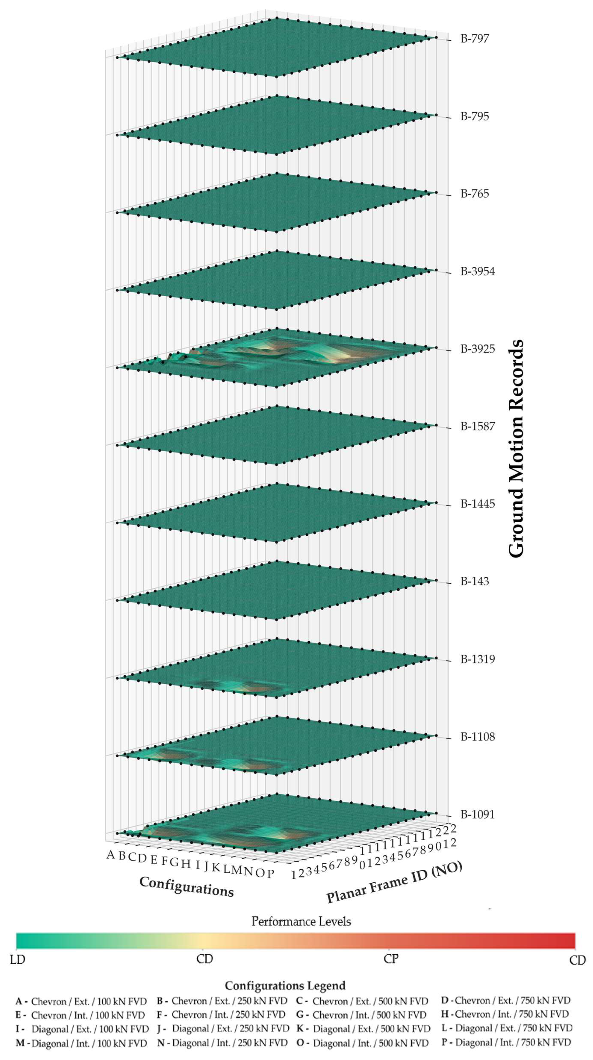
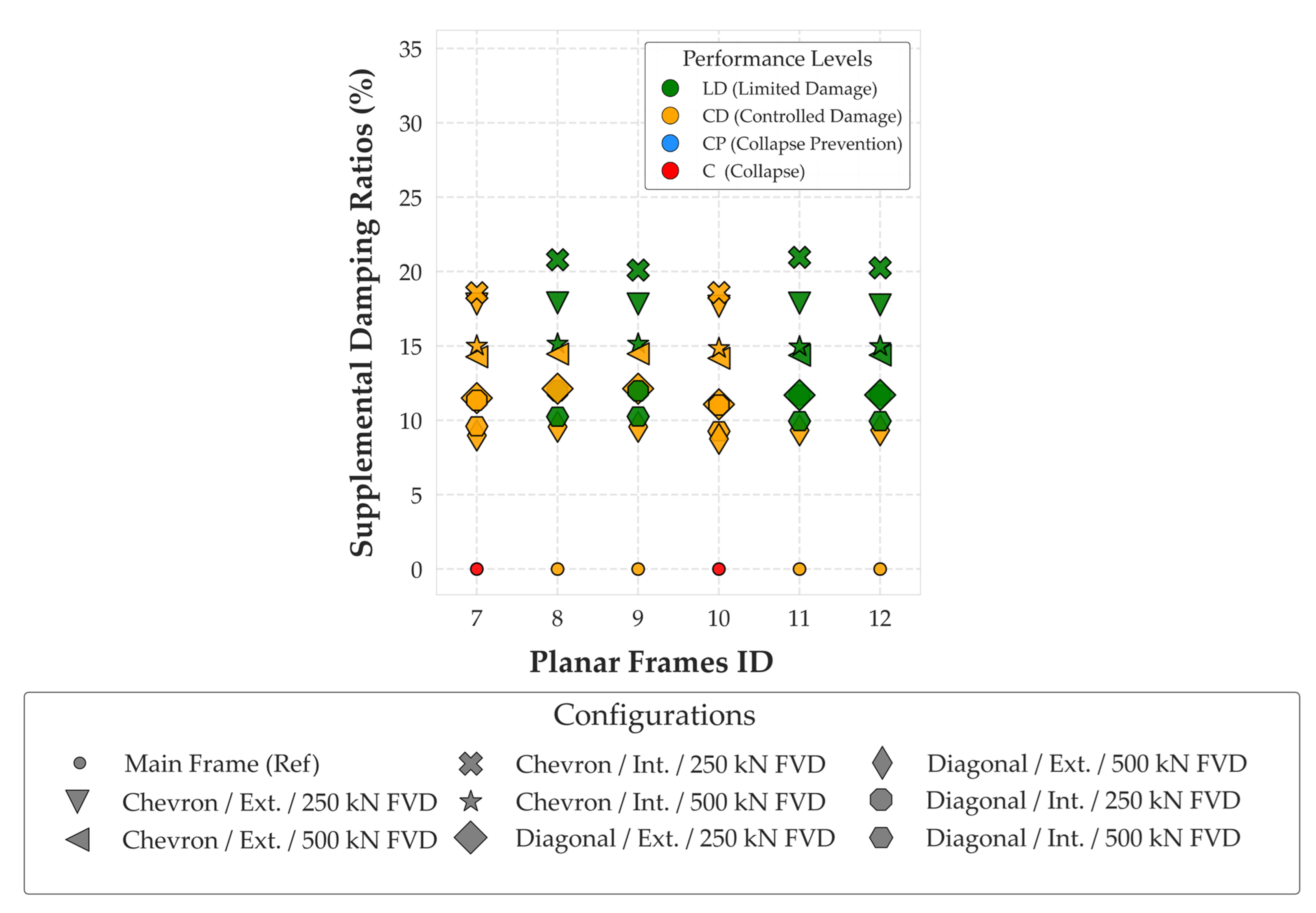
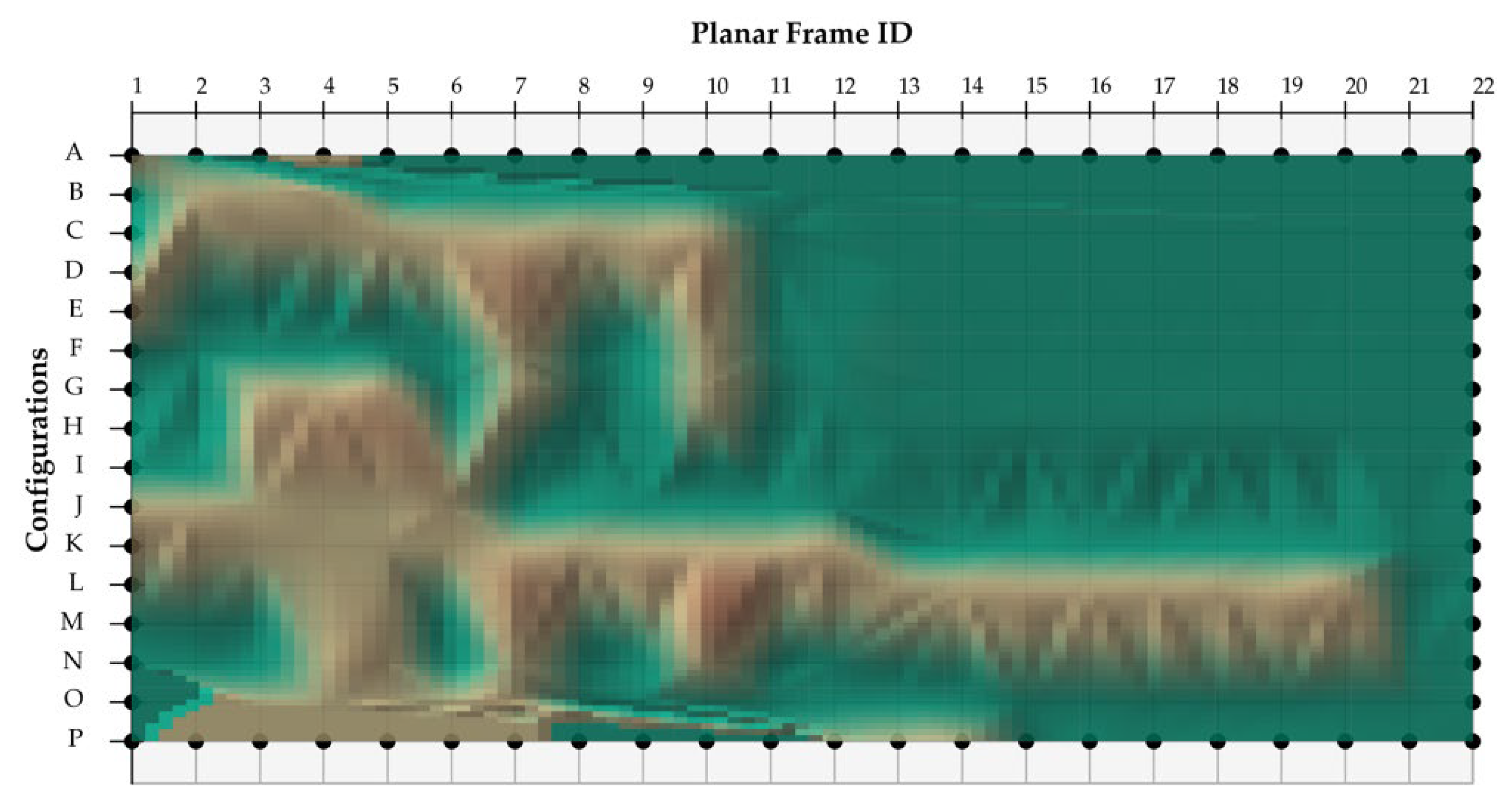
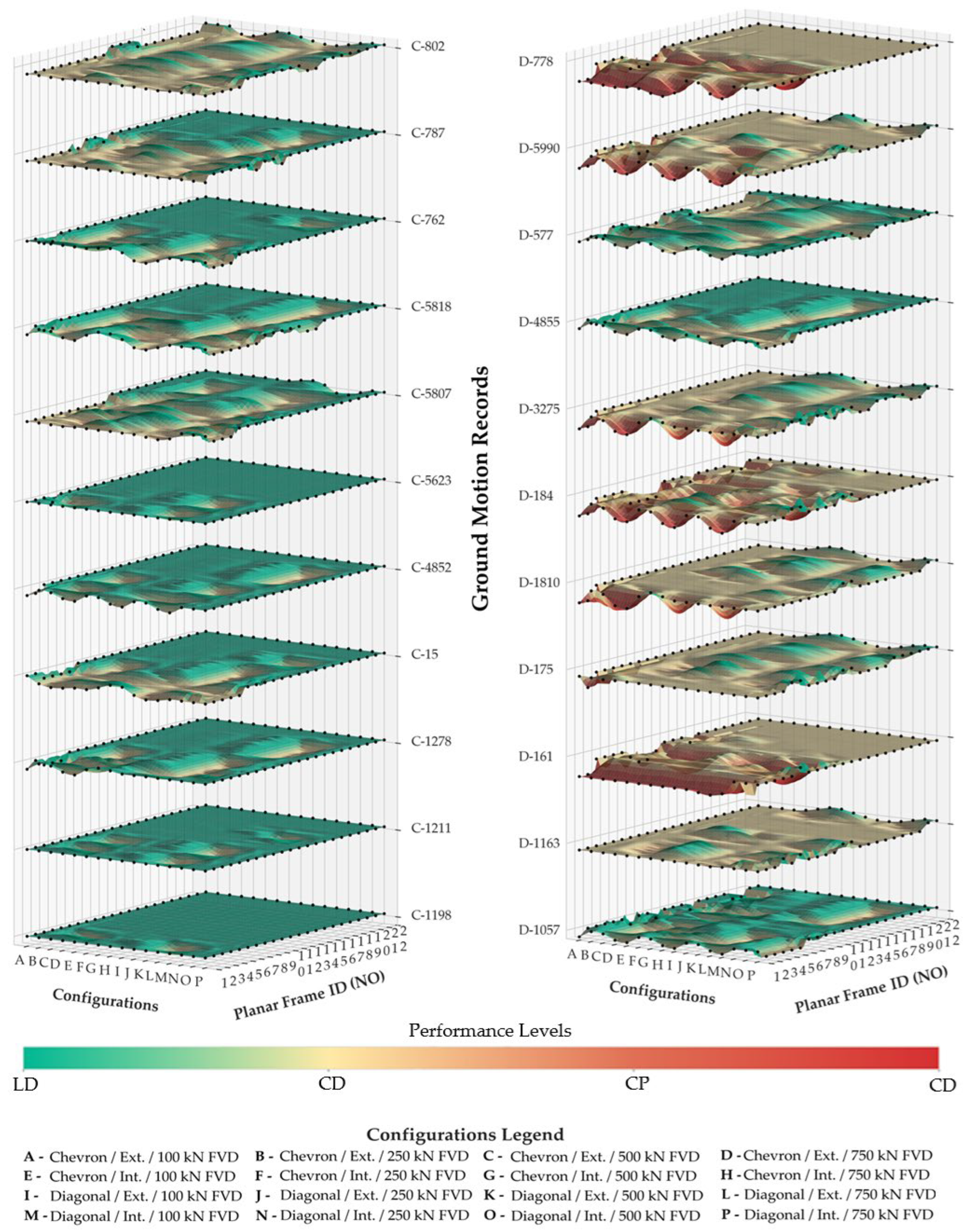
Figure 14 presents a representative performance map derived from Figure 15, in which the planar frame ID (NO) is selected on the horizontal axis and the damping system configuration on the vertical axis, from which the corresponding performance level is identified. The seismic performance results for all planar frames with different damping system configurations, obtained from a total of 22 individual ground-motion records corresponding to two site classes (C and D), are presented in Figure 15.
The green regions (for example, FC No 22 and internal diagonal-type FVDs with a rated force of 750 kN) indicate that the frames satisfy the Limited Damage (LD) performance level criteria, whereas red regions represent Collapse (C) of the structure. In summary, green-dominated regions indicate optimal seismic performance of the damper–structure system, as these regions represent configurations where the target performance objectives are achieved due to effective damper–structure interaction.
When the results for planar frame systems located in the Site Class C and D are compared, it is observed that the damper–structure systems located in the Site Class C generally satisfy the performance level of Controlled Damage (CD). However, performance evaluations in international seismic codes are generally based on the mean responses obtained from analyses using a specified number of ground-motion records, and the related assessment is presented in Section 5.5. The results corresponding to the Site Class B are presented in Figure A7.

5.5. Proposed Approach

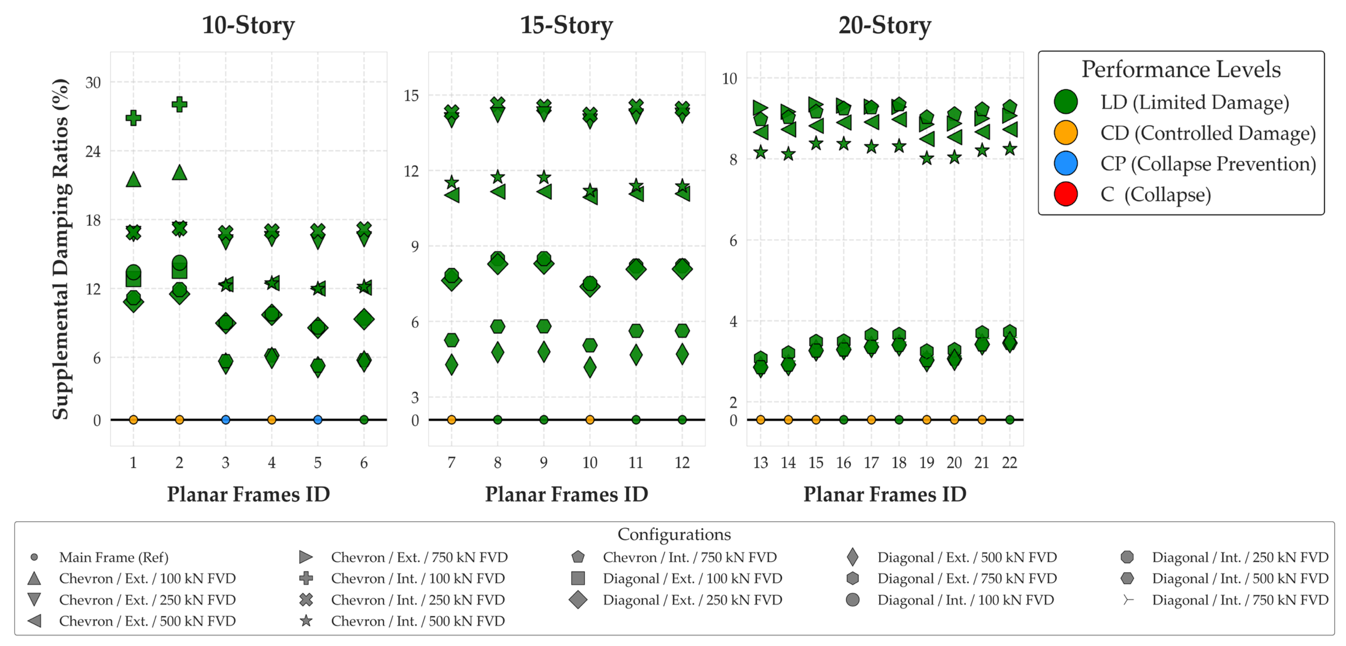
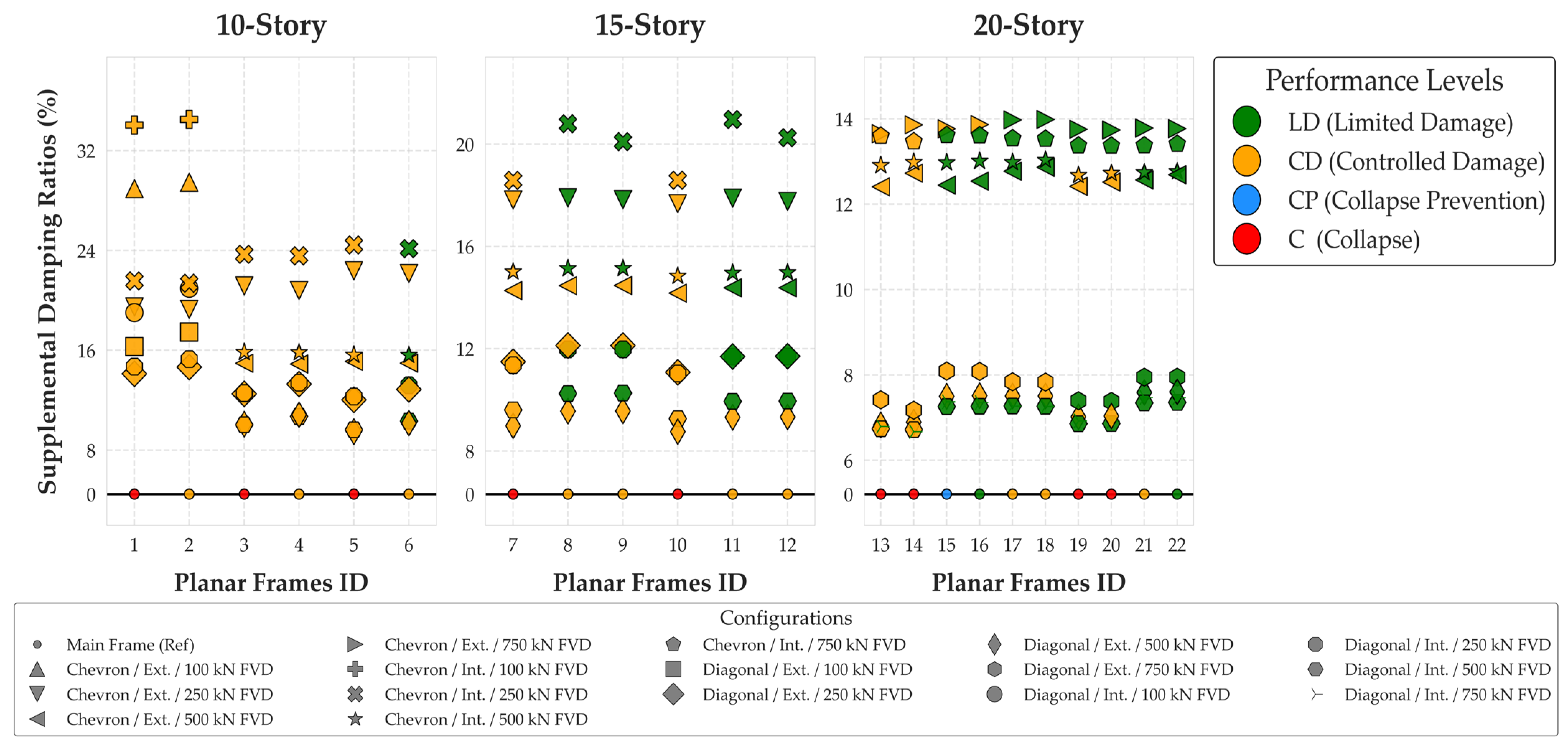
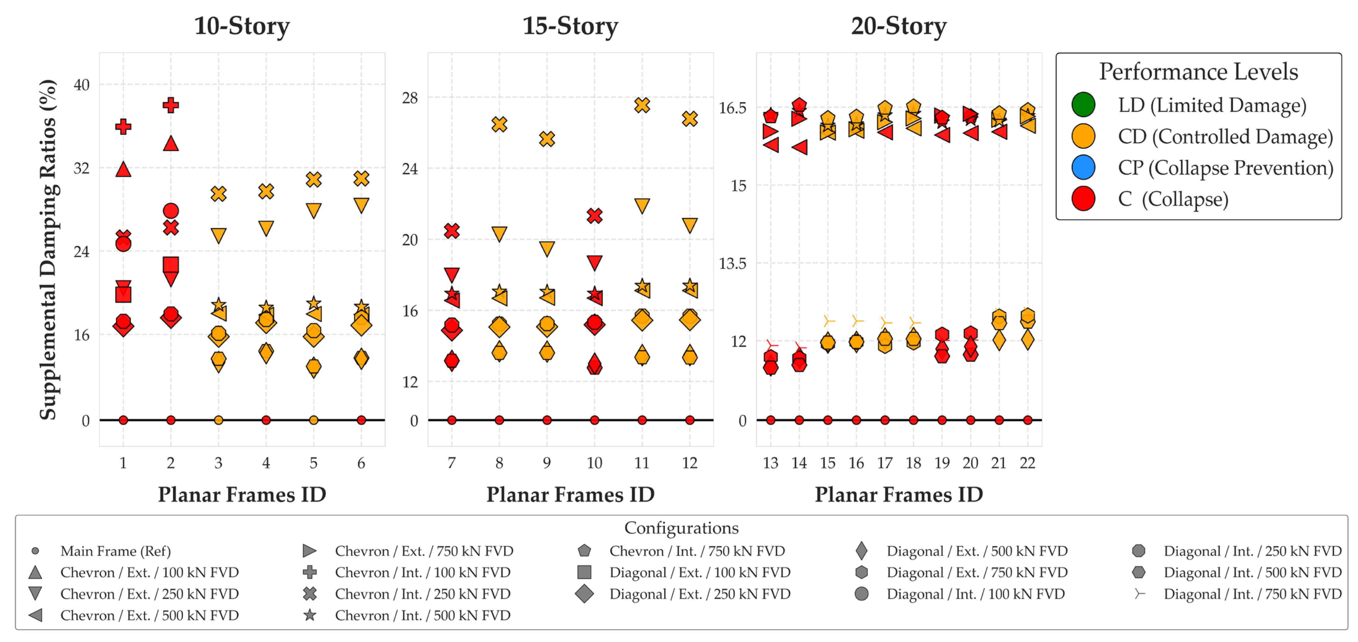
Following the proposed approach, NTHA were performed using 11 scaled ground-motion records for each of the Site Class B, C, and D. The mean response values obtained from these analyses were used to determine the supplemental damping ratios and the corresponding seismic performance of the planar frames (Figure 16, Figure 17 and Figure 18).
In the proposed approach, the supplemental damping ratio, which is required to satisfy the specific performance level criteria, can be directly estimated according to the site class and damper configuration of the structure to be designed or retrofitted.
As an illustrative example demonstrating the application of the proposed approach, Figure 16 shows that, the selection of the internal chevron damper configuration with a rated force of 250 kN for Frame Configuration (FC) No 6 results in the Limited Damage (LD) performance level, whereas the same damping system applied to FC No 5 satisfy the Controlled Damage (CD) performance level.
As another example for a 15-story building, it was determined that selecting a system similar to FC No 10 is capable of satisfying the target performance (Controlled Damage-CD) level in Site Class C, as shown in Figure 17. When an optimization assessment is considered for this case, selecting the column type C2 (FC No 11 and 12) instead of C1 (FC No 10) (see Table 2 for member properties) provides better structural performance (Limited Damage) with almost the same supplemental damping ratio. Furthermore, for the FC No 11 and 12, diagonal-braced FVDs with a rated force of 250 kN, either internal or external, provide the same seismic performance with a lower supplemental damping ratio compared to chevron-type dampers (Figure 17).
Alternatively, a systematic optimization assessment can be performed by examining the results obtained from similar configurations. For instance, as it is observed from Figure 18, a structural system similar to FC No 2 does not satisfy the target performance level (CD) in Site Class D. However, FC No 3–6 satisfy the target performance level requirements. Each different damper type and configuration provides an improvement in structural performance with different supplemental damping ratio levels, as shown in Figure 18. A design engineer can select a damper type and configuration among different alternatives that satisfy the target performance level requirements, as shown in Figure 16, Figure 17 and Figure 18.
Furthermore, under design-based earthquakes, the planar frames investigated for Site Class B exhibit elastic behavior and therefore satisfy the Limited Damage (LD) performance level. Accordingly, the required supplemental damping ratios are lower than those for Site Classes C and D.
Higher damper capacity does not always result in increased SDR. As an example, for the 15-story frames located on Site Class B, FC No 9 equipped with internal chevron-type FVDs, increasing the damper-rated force from 250 kN to 500 kN does not result in a higher supplemental damping ratio; instead, the configuration with the 250 kN dampers provides approximately 32% higher supplemental damping than the 500 kN damping system.
For Site Class C, it was observed that the investigated planar frames equipped with all types of damping system configurations satisfied the target performance level (Controlled Damage). Moreover, for some frame–damping system configurations, a higher performance level (Limited Damage) was achieved. Consequently, FC No 6 (10-story frames), FC No 11 and 12 (15-story frames), and FC No 15–22 (20-story frames) were found to be more optimal for application in Site Class C.
For FC No 12 with a diagonal external damper configuration, the system equipped with 500 kN dampers satisfies the Controlled Damage (CD) performance level. In contrast, reducing the damper capacity to 250 kN, while keeping all other damper properties unchanged, enables the structure to satisfy the Limited Damage (LD) performance level, providing approximately 20% higher supplemental damping. This result indicates that a higher damper capacity does not require improved seismic performance.
For Site Class D, only some planar frames equipped with the damping systems satisfied the Controlled Damage Performance Level. Furthermore, none of the sample frames satisfy the requirement of Limited Damage Performance Level (Figure 18). The results indicate that the structural system, supplemental damping ratio, or damper configuration must be revised so that a suitable solution can be found for buildings located on Site Class D, for the desired performance level of Limited Damage. In conclusion, the proposed approach using key governing parameters provides an effective and practical tool by eliminating the need for iteration. For future studies, by defining additional key parameters, the scope of the graphical approaches can be expanded, and a flexible non-iterative approach can be developed for the different target performances.

5.6. Limitations of Proposed Procedure and Approach

The proposed design, retrofitting procedure, and approach are assumed to be suitable for symmetric building systems without structural irregularities. All dampers used in the proposed procedure and approach have identical characteristics. Although this approach is commonly adopted in practice, this assumption may cause some dampers to operate below their capacity or be overdesigned.

6. Conclusions

This study proposes a supplemental damping-based design and retrofitting procedure for reinforced concrete buildings with PEDS, integrating site class into the process. NTHAs were systematically performed on planar reinforced concrete frames with different heights, member properties, damper configurations, and site classes. The results indicate that the SDR is a governing parameter in controlling seismic response, and improvements in structural performance can be provided by selecting the proper damper type and configuration. The following conclusions are drawn from the results of this study:
  • As illustrated in Figure 16, Figure 17 and Figure 18, the supplemental damping ratio required to achieve a given performance level exhibits a decreasing trend with increasing building height for all site classes. As seen from Figure 17, for 10-story buildings located on Site Class C, the SDR required to satisfy the Controlled Damage (CD) performance level varies within the range of approximately 10% to 34%, while the required SDR for 20-story buildings reduces approximately 7–14%.
  • The influence of adverse soil conditions is most pronounced for Site Class D, where none of the investigated systems can achieve the Limited Damage (LD) level; on the other hand, 9% SDR is sufficient for 20-story buildings located on Site Class B.
  • These findings clearly demonstrate that soil class is a governing parameter affecting the required supplemental damping ratio, and that soil conditions should be considered with building height in the design and optimization of damping systems.
  • The results suggest that structural systems with improved ductile behavior engage damping devices more effectively, which contributes to increased roof displacement reductions and a more efficient dissipation of seismic deformation demands.
  • Damper effectiveness is not always sensitive to damper arrangement. For example, as shown in Figure 16, for FC No 10 located on Site Class B, the diagonal damper configuration with a rated force of 250 kN provides a supplemental damping ratio of approximately 8% for both arrangements.
  • Diagonal and chevron dampers with identical capacity provide comparable displacement reductions; chevron configurations satisfy higher SDR, leading to improved structural performance.
  • Higher damper capacity does not always result in increased SDR. This indicates that damper effectiveness is governed by the interaction between the damper and the structural system, rather than by damper capacity. Using the proposed approach, which explicitly considers structure–damper interaction, such results can be identified directly and efficiently.
  • A higher damper capacity does not always provide a higher structural performance. Using the proposed approach, such cases in which a lower damper capacity results in a more favorable performance level can be identified directly and efficiently without requiring iterative analyses.
Consequently, selecting a damper configuration aligned with the characteristics of the structural system is critical to achieving the target seismic performance. Overall, the proposed supplemental damping-based non-iterative approach enables rapid and reliable identification of target performance states by directly relating the supplemental damping ratio to seismic performance levels. The proposed approach not only reduces the need for iterations in the design or retrofitting of structures equipped with damper systems but also provides an effective tool for identifying optimal system configurations.
Future studies may focus on developing the proposed procedure for irregular buildings. Irregularity-dependent correction factors may be introduced to scale the required SDR. Furthermore, the effects of non-uniform damper capacity distribution along the height of the building on structural response and damping effectiveness may be examined within the scope of future studies. As mentioned earlier, the study is based on two-dimensional structural models. In three-dimensional systems, additional effects such as torsional response may arise. Therefore, the results obtained in this study should be applied to three-dimensional structural systems with due caution. Future research should extend the proposed approach to three-dimensional systems to account for torsional effects.

Author Contributions

Methodology, Ş.K. and M.S.K.; data curation, Ş.K.; writing—original draft preparation, Ş.K. and M.S.K.; supervision, M.S.K. All authors have read and agreed to the published version of the manuscript.

Funding

This research received no external funding.

Data Availability Statement

The original contributions presented in this study are included in this article. Further inquiries can be directed to the corresponding author.

Conflicts of Interest

The remaining authors declare that the research was conducted in the absence of any commercial or financial relationships that could be construed as a potential conflict of interest.

Nomenclature

aExponential constant
AModal roof displacement normalized to unit value
CFVDDamping coefficient
dbReinforcement bar diameter
DDead load
DRMSRoot-mean-square difference
E d H Horizontal seismic effect
E d V Vertical seismic effect
EDDissipated energy
ESStrain energy
fcConcrete compressive strength
fyReinforcement yield strength
FFVDEffective damper force
hCross-section depth
kbStiffness of bracing members
kdStiffness of FVD
kdb,LStiffness of linear FVD with bracing member
kdb,NLStiffness of nonlinear FVD with bracing member
LLive load
LeffEffective live load
LpPlastic hinge length
LsShear span
mEffective story mass
nLive load reduction factor
NNumber of identical damped bracing members in a story
QUDDeformation-based action caused by gravity loads and earthquake forces
S Snow load
S1, SSSpectral coefficients
Sa R ( T i ) Spectral acceleration of the ground motion record at period Ti
Sa T ( T i ) Spectral acceleration of the target spectra at period Ti
TNatural vibration period
Tj, TkLower and upper limits of the period range for spectral scaling
uRelative displacement between the damper ends
u ˙ Relative velocity between the damper ends
ud0Relative displacement between the damper ends in the damping system
udb0Relative disp. between the braced damper ends in the damping system
uKStory displacement in the fundamental mode
αScale factor
θ p ( CP ) Maximum allowable plastic rotation for Collapse Prevention
θyYield rotation
θuUltimate rotation
ϕyYield curvature
ϕuUltimate curvature
ωCircular frequency
ωnNatural circular frequency
ηCoefficient defined in TBEC 2018 [83], taken as 1.0 for beams and columns
ξeqEquivalent viscous damping ratio or supplemental damping ratio
θInclination angle of the braced damper
λParameter calculated by the expression 2 2   +   a Γ 2   ( 1   +   a / 2 )   Γ ( 2   +   a )
Γ Gamma function

Appendix A

Table A1. Distribution of RC members in 15 and 20-story planar reinforced concrete frames.
Frame IDStoryColumn TypeBeam Type
71–10C2B6
11–15C1B6
81–10C2B7
11–15C2B6
91–10C2B7
11–15C2B7
101–10C3B6
11–15C1B6
111–10C3B7
11–15C2B6
121–10C3B7
11–15C2B7
131–10C4B6
11–20C1B6
141–10C4B6
11–20C2B6
151–10C4B7
11–20C1B6
161–10C4B7
11–20C1B7
171–10C4B7
11–20C2B6
181–10C4B7
11–20C2B7
191–10C5B8
11–20C2B6
201–10C5B8
11–20C2B7
211–10C5B9
11–20C3B6
221–10C5B9
11–20C3B7
Table A2. Properties of selected ground motion records for Site Class C and scaling factors.
Earthquake
Name
YearStation NameRecord Sequence NumberMagnitudeMechanism
(Fault Style)
Epicentral
Distance (km)
Scaling Factor
Kern County1952Taft Lincoln Sch.157.36Reverse432.85
Loma Prieta1989Fremont–M. SJ7626.93Reverse Oblique553.94
Loma Prieta1989Palo Alto–S. L.7876.93Reverse Oblique511.29
Loma Prieta1989Saratoga–A. A.8026.93Reverse Oblique271.02
Chi-Chi, Taiwan1999CHY02911987.62Reverse Oblique401.23
Chi-Chi, Taiwan1999CHY05212117.62Reverse Oblique713.45
Chi-Chi, Taiwan1999HWA02912787.62Reverse Oblique772.44
Chuetsu-oki, Japan2007Joetsu, A. Dist.48526.80Reverse574.32
Iwate, Japan2008IWT01556236.90Reverse344.47
Iwate, Japan2008Yuzama Y.58076.90Reverse372.86
Iwate, Japan2008Kurihara City58186.90Reverse250.91
Table A3. Properties of selected ground motion records for Site Class D and scaling factors.
Earthquake
Name
YearStation NameRecord Sequence NumberMagnitudeMechanism
(Fault Style)
Epicentral
Distance (km)
Scaling Factor
Imperial Valley-061979Brawley Airport1616.53Strike Slip431.87
Imperial Valley-061979El Centro A. #121756.53Strike Slip322.81
Imperial Valley-061979El Centro D. A.1846.53Strike Slip271.17
Taiwan SMART1(45)1986SMART1 O015777.30Reverse782.04
Loma Prieta1989Hollister D.I A.7786.93Reverse Oblique451.47
Northridge-011994Playa Del R.–S.10576.69Reverse303.21
Kocaeli, Turkey1999Hava Alani11637.51Strike Slip1023.68
Hector Mine1999Mecca–C. Yard18107.13Strike Slip1183.24
Chi-Chi, Taiwan-061999CHY03632756.30Reverse622.56
Chuetsu-oki, Japan2007Sanjo48556.80Reverse322.78
El Mayor-C., Mexico2010El Centro A. #759907.20Strike Slip632.92
Figure A1. Base reaction of 15-Story frames for Site Class B–C–D.
Buildings 16 00711 g0a1
Figure A2. Base reaction of 20-story frames for Site Class B–C–D.
Buildings 16 00711 g0a2
Figure A3. Roof displacement of 15-Story frames for Site Class B–C–D.
Buildings 16 00711 g0a3
Figure A4. Roof displacement of 20-Story frames for Site Class B–C–D.
Buildings 16 00711 g0a4
Figure A5. Supplemental damping ratios of 15-Story frames for Site Class B–C–D.
Buildings 16 00711 g0a5
Figure A6. Supplemental damping ratios of 20-Story frames for Site Class B–C–D.
Buildings 16 00711 g0a6
Figure A7. Performance state of frames for Site Class B.
Buildings 16 00711 g0a7

References

  1. Grigorian, C.E.; Yang, T.S.; Popov, E.P. Slotted bolted connection energy dissipators. Earthq. Spectra 1993, 9, 491–504. [Google Scholar] [CrossRef] [Scilit]
  2. Iwata, M.; Kato, T.; Wada, A. Buckling-restrained braces as hysteretic dampers. In Proceedings of the Third International Conference STESSA 2000, Montreal, QC, Canada, 21–24 August 2000. [Google Scholar]
  3. Makris, N.; Constantinou, M.C.; Dargush, G.F. Analytical model of viscoelastic fluid dampers. J. Struct. Eng. 1993, 119, 3310–3325. [Google Scholar] [CrossRef] [Scilit]
  4. Constantinou, M.C.; Symans, M.D. Experimental study of seismic response of buildings with supplemental fluid dampers. Struct. Des. Tall Build. 1993, 2, 93–132. [Google Scholar] [CrossRef] [Scilit]
  5. Chang, K.C.; Lai, M.L.; Soong, T.T.; Hao, D.S.; Yeh, Y.C. Seismic Behavior and Design Guidelines for Steel Frame Structures with Added Viscoelastic Dampers; NCEER-93-0009; National Center for Earthquake Engineering Research: Buffalo, NY, USA, 1993. [Google Scholar]
  6. Shen, K.L.; Soong, T.T. Modeling of viscoelastic dampers for structural applications. J. Eng. Mech. 1995, 121, 694–701. [Google Scholar] [CrossRef] [Scilit]
  7. Aiken, I.D.; Kelly, J.M. Earthquake Simulator Testing and Analytical Studies of Two Energy-Absorbing Systems for Multistory Structures; UCB/EERC-90/03; Earthquake Engineering Research Center: Berkeley, CA, USA, 1990. [Google Scholar]
  8. Molina, F.; Sorace, S.; Terenzi, G.; Magonette, G.; Viaccoz, B. Seismic tests on reinforced concrete and steel frames retrofitted with dissipative braces. Earthq. Eng. Struct. Dyn. 2004, 33, 1515–1533. [Google Scholar] [CrossRef] [Scilit]
  9. Chang, K.C.; Soong, T.T.; Oh, S.T.; Lai, M.L. Seismic Response of a 2/5 Scale Steel Structure with Added Viscoelastic Dampers; NCEER-91-0012; National Center for Earthquake Engineering Research: Buffalo, NY, USA, 1991. [Google Scholar]
  10. Lin, R.C.; Liang, Z.; Soong, T.T.; Zhang, R.H.; Mahmoodi, P. Experimental study on seismic behaviour of viscoelastically damped structures. Eng. Struct. 1991, 13, 75–84. [Google Scholar] [CrossRef] [Scilit]
  11. Shen, K.L.; Soong, T.T.; Chang, K.C.; Lai, M.L. Seismic behaviour of reinforced concrete frames with added viscoelastic dampers. Eng. Struct. 1995, 17, 372–380. [Google Scholar] [CrossRef] [Scilit]
  12. Chang, K.C.; Chen, S.J.; Lai, M.L. Inelastic behavior of steel frames with added viscoelastic dampers. J. Struct. Eng. 1996, 122, 1178–1186. [Google Scholar] [CrossRef] [Scilit]
  13. Mrad, C.; Titirla, M.D.; Larbi, W. Comparison of strengthening solutions with optimized passive energy dissipation systems in symmetric buildings. Appl. Sci. 2021, 11, 10103. [Google Scholar] [CrossRef] [Scilit]
  14. Chen, X.; Li, J.; Cheang, J. Seismic performance analysis of Wenchuan Hospital structure with viscous dampers. Struct. Des. Tall Spec. Build. 2010, 19, 397–419. [Google Scholar] [CrossRef] [Scilit]
  15. Guo, T.; Xu, J.; Xu, W.; Di, Z. Seismic upgrade of existing buildings with fluid viscous dampers: Design methodologies and case study. J. Perform. Constr. Facil. 2014, 29, 04014103. [Google Scholar] [CrossRef] [Scilit]
  16. Gong, S.; Zhou, Y.; Ge, P. Seismic analysis for tall and irregular temple buildings using nonlinear viscoelastic dampers. Struct. Des. Tall Spec. Build. 2016, 26, e1352. [Google Scholar] [CrossRef] [Scilit]
  17. Sorace, S.; Terenzi, G. Nonlinear dynamic modelling and design procedure of fluid viscous spring-dampers for base isolation. Eng. Struct. 2001, 23, 1556–1567. [Google Scholar] [CrossRef] [Scilit]
  18. Sorace, S.; Terenzi, G. Analysis and demonstrative application of a base isolation–supplemental damping technology. Earthq. Spectra 2008, 24, 775–793. [Google Scholar] [CrossRef] [Scilit]
  19. Wolff, E.D.; Ipek, C.; Constantinou, M.C.; Tapan, M. Effect of viscous damping devices on the response of seismically isolated structures. Earthq. Eng. Struct. Dyn. 2014, 44, 185–198. [Google Scholar] [CrossRef] [Scilit]
  20. Constantinou, M.C.; Soong, T.T.; Dargush, G.F. Passive Energy Dissipation Systems for Structural Design and Retrofit; MCEER Monograph No.1; Multidisciplinary Center for Earthquake Engineering Research: Buffalo, NY, USA, 1998. [Google Scholar]
  21. Moreschi, L.M. Seismic Design of Energy Dissipation Systems for Optimal Structural Performance. Ph.D. Thesis, Virginia Polytechnic Institute and State University, Blacksburg, VA, USA, 2000. [Google Scholar]
  22. Siami Kaleybar, R.; Tehrani, P. Effects of damper arrangement and type on seismic performance of steel moment frames. Structures 2021, 33, 3382–3396. [Google Scholar] [CrossRef] [Scilit]
  23. Catalan, A.; Rizzo, F.; Cahis, X.; Sabba, M.F.; Foti, D. Modelling and application of buckling-restrained braces for performance-based earthquake engineering frameworks. J. Vib. Eng. Technol. 2025, 13, 167. [Google Scholar] [CrossRef] [Scilit]
  24. Durgun, Y. Mevcut Betonarme Yapıların Deprem Performanslarının Belirlenmesi ve Viskoz Akışkanlı Sönümleyiciler ile Güçlendirilmesi İçin Artımsal Analize Dayalı bir Algoritma. Ph.D. Thesis, Istanbul Technical University, Istanbul, Türkiye, 2013. [Google Scholar]
  25. De Domenico, D.; Ricciardi, G.; Takewaki, I. Design strategies of viscous dampers for seismic protection of building structures: A review. Soil Dyn. Earthq. Eng. 2019, 118, 144–165. [Google Scholar] [CrossRef] [Scilit]
  26. Lin, Y.Y.; Tsai, M.H.; Hwang, J.S.; Chang, K.C. Direct displacement-based design for buildings with passive energy dissipation systems. Eng. Struct. 2003, 25, 25–37. [Google Scholar] [CrossRef] [Scilit]
  27. Bergami, A.V.; Nuti, C. Design procedure of dissipative braces for seismic upgrading of structures. Earthq. Struct. 2013, 4, 85–108. [Google Scholar] [CrossRef] [Scilit]
  28. Mazza, F.; Vulcano, A. Displacement-based design procedure of damped braces for seismic retrofitting of RC framed buildings. Bull. Earthq. Eng. 2014, 13, 2121–2143. [Google Scholar] [CrossRef] [Scilit]
  29. Kim, J.; Choi, H.; Chung, L. Energy-based seismic design of structures with buckling-restrained braces. Steel Compos. Struct. 2004, 4, 437–452. [Google Scholar] [CrossRef] [Scilit]
  30. Hareen, C.B.V.; Mohan, S.C. Energy-based seismic retrofit and design of building frames with passive dampers. Eng. Struct. 2022, 250, 113412. [Google Scholar] [CrossRef] [Scilit]
  31. Landi, L.; Lucchi, S.; Diotallevi, P.P. Seismic retrofit strategies of RC frames equipped with damping devices. Earthq. Struct. 2017, 12, 123–138. [Google Scholar] [CrossRef] [Scilit]
  32. Huergo, I.F.; Hernández-Barrios, H.; Patlán, C.M. A continuous–discrete approach for predesign of flexible-base tall buildings with fluid viscous dampers. Soil Dyn. Earthq. Eng. 2020, 131, 10604. [Google Scholar] [CrossRef] [Scilit]
  33. Pall, A.S.; Marsh, C. Response of friction-damped braced frames. J. Struct. Div. 1982, 108, 1313–1323. [Google Scholar] [CrossRef] [Scilit]
  34. Filiatrault, A.; Cherry, S. Seismic design spectra for friction-damped structures. J. Struct. Eng. 1990, 116, 1334–1355. [Google Scholar] [CrossRef] [Scilit]
  35. Colajanni, P.; Papia, M. Seismic response of braced frames with and without friction dampers. Eng. Struct. 1995, 17, 129–140. [Google Scholar] [CrossRef] [Scilit]
  36. Moreschi, L.; Singh, M. Design of yielding metallic and friction dampers for optimal seismic performance. Earthq. Eng. Struct. Dyn. 2003, 32, 1291–1311. [Google Scholar] [CrossRef] [Scilit]
  37. Levy, R.; Lavan, O.; Rutenberg, A. Seismic design of friction-damped braced frames based on historical records. Earthq. Spectra 2005, 21, 761–778. [Google Scholar] [CrossRef] [Scilit]
  38. Taiyari, F.; Mazzolani, F.M.; Bagheri, S. Damage-based optimal design of friction dampers in multistory chevron-braced steel frames. Soil Dyn. Earthq. Eng. 2019, 119, 11–20. [Google Scholar] [CrossRef] [Scilit]
  39. Ghorbani, H.R.; Rofooei, F.R. A novel double slip-load friction damper to control the seismic response of structures. Eng. Struct. 2020, 225, 111273. [Google Scholar] [CrossRef] [Scilit]
  40. Monir, H.S.; Zeynali, K. A modified friction damper for diagonal bracing of structures. J. Constr. Steel Res. 2013, 87, 17–30. [Google Scholar] [CrossRef] [Scilit]
  41. Mualla, I.H.; Belev, B. Performance of steel frames with a new friction damper device under earthquake excitation. Eng. Struct. 2002, 24, 365–371. [Google Scholar] [CrossRef] [Scilit]
  42. Kersting, R.; Fahnestock, L.; Lopez, W. Seismic Design of Steel Buckling-Restrained Braced Frames: A Guide for Practicing Engineers; NEHRP Seismic Design Technical Brief 11; U.S. Department of Commerce National Institute of Standards and Technology Engineering Laboratory: Gaithersburg, MD, USA, 2015. [Google Scholar]
  43. Ko, E.; Kimura, I.; Clark, P.; Aiken, I. Design procedures for buildings incorporating hysteretic damping devices. In Proceedings of the 68th SEAOC Annual Convention, Sacramento, CA, USA, 30 September–3 October 1999. [Google Scholar]
  44. Kim, J.; Choi, H. Behavior and design of structures with buckling-restrained braces. Eng. Struct. 2004, 26, 693–706. [Google Scholar] [CrossRef] [Scilit]
  45. Asgarian, B.; Shokrgozar, H.R. BRBF response modification factor. J. Constr. Steel Res. 2009, 65, 290–298. [Google Scholar] [CrossRef] [Scilit]
  46. Pan, Y.; An, R.; Bai, J.; Yan, X.; Jin, S. Seismic design and performance analysis of buckling-restrained braced RC frame structures. Struct. Des. Tall Spec. Build. 2019, 28, e1661. [Google Scholar] [CrossRef] [Scilit]
  47. Zhou, Y.; Zhang, C.; Lu, X. Seismic performance of a damping outrigger system for tall buildings. Struct. Control Health Monit. 2016, 24, e1864. [Google Scholar] [CrossRef] [Scilit]
  48. Jiang, H.; Li, S.; Zhu, Y. Seismic performance of high-rise buildings with energy-dissipation outriggers. J. Constr. Steel Res. 2017, 134, 80–91. [Google Scholar] [CrossRef] [Scilit]
  49. Constantinou, M.C.; Symans, M.D. Experimental and Analytical Investigation of Seismic Response of Structures with Supplemental Fluid Viscous Dampers; NCEER-92-0032; National Center for Earthquake Engineering Research: Buffalo, NY, USA, 1992. [Google Scholar]
  50. Constantinou, M.C.; Reinhorn, A.M.; Li, C. Experimental and Analytical Investigation of Seismic Retrofit of Structures with Supplemental Damping, Part 1: Fluid Viscous Damping Devices; NCEER-95-0001; National Center for Earthquake Engineering Research: Buffalo, NY, USA, 1995. [Google Scholar]
  51. Seleemah, A.A.; Constantinou, M.C. Investigation of Seismic Response of Buildings with Linear and Nonlinear Fluid Viscous Dampers; NCEER-97-0004; National Center for Earthquake Engineering Research: Buffalo, NY, USA, 1997. [Google Scholar]
  52. Hwang, J.-S.; Huang, Y.-N.; Yi, S.-L.; Ho, S.-Y. Design formulations for supplemental viscous dampers to building structures. J. Struct. Eng. 2008, 134, 22–31. [Google Scholar] [CrossRef] [Scilit]
  53. Silvestri, S.; Gasparini, G.; Trombetti, T. A five-step procedure for the dimensioning of viscous dampers in building structures. J. Earthq. Eng. 2010, 14, 417–447. [Google Scholar] [CrossRef] [Scilit]
  54. Sepehri, A.; Taghikhany, T.; Ahmadi Namin, S.M.R. Seismic design and assessment of structures with viscous dampers at limit state levels. Struct. Des. Tall Spec. Build. 2018, 28, e1569. [Google Scholar] [CrossRef] [Scilit]
  55. Banazadeh, M.; Ghanbari, A. Seismic performance assessment of steel moment-resisting frames with linear and nonlinear viscous dampers. J. Constr. Steel Res. 2017, 136, 215–228. [Google Scholar] [CrossRef] [Scilit]
  56. Rajeswaran, G.; Wijeyewickrema, A.C. Alternative design method for seismic retrofit of RC moment-resisting frames with viscous dampers. J. Earthq. Eng. 2019, 26, 240–270. [Google Scholar] [CrossRef] [Scilit]
  57. Constantinou, M.C.; Whittaker, A.S.; Kalpakidis, Y.; Fenz, D.M.; Warn, G.P. Performance of Seismic Isolation Hardware Under Service and Seismic Loading; MCEER-07-0012; Multidisciplinary Center for Earthquake Engineering Research: Buffalo, NY, USA, 2007. [Google Scholar]
  58. Lobo, R.F.; Bracci, J.M.; Shen, K.L.; Reinhorn, A.M.; Soong, T.T. Inelastic Response of Reinforced Concrete Structures with Viscoelastic Braces; NCEER-93-0006; National Center for Earthquake Engineering Research: Buffalo, NY, USA, 1993. [Google Scholar]
  59. Zhang, R.; Soong, T.T.; Mahmoodi, P. Seismic response of steel frame structures with added viscoelastic dampers. Earthq. Eng. Struct. Dyn. 1989, 18, 389–396. [Google Scholar] [CrossRef] [Scilit]
  60. Zhang, R.; Soong, T.T. Seismic design of viscoelastic dampers for structural applications. J. Struct. Eng. 1992, 118, 1375–1392. [Google Scholar] [CrossRef] [Scilit]
  61. Kim, J.; Choi, H. Displacement-based design of supplemental dampers for seismic retrofit of framed structures. J. Struct. Eng. 2006, 132, 873–883. [Google Scholar] [CrossRef] [Scilit]
  62. Mazza, F.; Vulcano, A. Control of earthquake and wind response of steel-framed buildings using viscoelastic dampers. Earthq. Eng. Struct. Dyn. 2011, 40, 155–174. [Google Scholar] [CrossRef] [Scilit]
  63. Tchamo, J.M.; Ying, Z. An alternative practical design method for structures with viscoelastic dampers. Earthq. Eng. Eng. Vib. 2018, 17, 459–473. [Google Scholar] [CrossRef] [Scilit]
  64. Xie, L.; Zhang, L.; Pan, C.; Zhang, R.; Chen, T. Uniform damping ratio-based design method for seismic retrofitting of elastoplastic RC structures using viscoelastic dampers. Soil Dyn. Earthq. Eng. 2020, 128, 105866. [Google Scholar] [CrossRef] [Scilit]
  65. Heydarinouri, H.; Zahrai, S.M. Iterative step-by-step procedure for optimal placement and design of viscoelastic dampers to improve damping ratio. Struct. Des. Tall Spec. Build. 2017, 26, e1361. [Google Scholar] [CrossRef] [Scilit]
  66. Hu, X.; Chen, Q.; Weng, D.; Zhang, R.; Ren, X. Estimation of additional equivalent damping ratio of damped structures based on energy dissipation. Adv. Civ. Eng. 2019, 2019, 8052413. [Google Scholar] [CrossRef] [Scilit]
  67. OpenSees, Version 3.7.1; Pacific Earthquake Engineering Research Center (PEER), University of California: Berkeley, CA, USA, 2025. Available online: https://opensees.berkeley.edu (accessed on 22 February 2023).
  68. Priestley, M.J.N. Myths and fallacies in earthquake engineering—Conflicts between design and reality. Bull. N. Z. Soc. Earthq. Eng. 1993, 26, 329–341. [Google Scholar] [CrossRef] [Scilit]
  69. Priestley, M.J.N.; Calvi, G.M.; Kowalsky, M.J. Displacement-based seismic design of structures. Earthq. Spectra 2008, 24, 555–577. [Google Scholar] [CrossRef] [Scilit]
  70. Maley, T.J.; Sullivan, T.J.; Di Corte, G. Development of a displacement-based design method for steel dual systems with buckling-restrained braces and moment-resisting frames. J. Earthq. Eng. 2010, 14, 106–140. [Google Scholar] [CrossRef] [Scilit]
  71. Sullivan, T.J.; Lago, A. Towards a simplified direct DBD procedure for seismic design of moment-resisting frames with viscous dampers. Eng. Struct. 2012, 35, 140–148. [Google Scholar] [CrossRef] [Scilit]
  72. Zahrah, T.; Hall, W.J. Earthquake energy absorption in SDOF structures. J. Struct. Eng. 1984, 110, 1757–1772. [Google Scholar] [CrossRef] [Scilit]
  73. Park, Y.J.; Ang, A.H.S. Mechanistic Seismic Damage Model for Reinforced Concrete. J. Struct. Eng. 1985, 111, 722–739. [Google Scholar] [CrossRef] [Scilit]
  74. Fajfar, P.; Vidic, T. Consistent inelastic design spectra: Hysteretic and input energy. Earthq. Eng. Struct. Dyn. 1994, 23, 523–532. [Google Scholar] [CrossRef] [Scilit]
  75. Manfredi, G. Evaluation of Seismic Energy Demand. Earthq. Eng. Struct. Dyn. 2001, 30, 485–499. [Google Scholar] [CrossRef] [Scilit]
  76. Arroyo, D.; Ordaz, M. On the estimation of hysteretic energy demands for SDOF systems. Earthq. Eng. Struct. Dyn. 2007, 36, 2365–2382. [Google Scholar] [CrossRef] [Scilit]
  77. Habibi, A.; Chan, R.W.K.; Albermani, F. Energy-based design method for seismic retrofitting with passive energy dissipation systems. Eng. Struct. 2013, 46, 77–86. [Google Scholar] [CrossRef] [Scilit]
  78. Sorace, S.; Terenzi, G. Seismic protection of frame structures by fluid viscous damped braces. J. Struct. Eng. 2008, 134, 45–55. [Google Scholar] [CrossRef] [Scilit]
  79. Constantinou, M.C.; Symans, M.D. Seismic response of structures with supplemental damping. Struct. Des. Tall Build. 1993, 2, 77–92. [Google Scholar] [CrossRef] [Scilit]
  80. Lin, Y.Y.; Chang, K.C. Study on damping reduction factor for buildings under earthquake ground motions. J. Struct. Eng. 2003, 129, 206–214. [Google Scholar] [CrossRef] [Scilit]
  81. Lin, Y.Y.; Chang, K.C. Effects of site classes on damping reduction factors. J. Struct. Eng. 2004, 130, 1667–1675. [Google Scholar] [CrossRef] [Scilit]
  82. Castillo, T.; Ruiz, S.E. Reduction factors for seismic design spectra for structures with viscous energy dampers. J. Earthq. Eng. 2014, 18, 323–349. [Google Scholar] [CrossRef] [Scilit]
  83. TBEC: Turkish Building Earthquake Code; General Directorate of Disaster and Emergency Management: Ankara, Turkey, 2018.
  84. ASCE 41-23; Seismic Evaluation and Retrofit of Existing Buildings. American Society of Civil Engineers: Reston, VA, USA, 2023.
  85. FEMA 356 NEHRP; Prestandard and Commentary for the Seismic Rehabilitation of Buildings. Federal Emergency Management Agency: Washington, DC, USA, 2000.
  86. Akcelyan, S.; Lignos, D.G.; Hikino, T.; Nakashima, M. Evaluation of analysis procedures for steel frames with supplemental damping devices based on full-scale shake table tests. J. Struct. Eng. 2016, 142, 04016024. [Google Scholar] [CrossRef] [Scilit]
  87. Kent, D.C.; Park, R. Flexural members with confined concrete. J. Struct. Div. 1971, 97, 1969–1990. [Google Scholar] [CrossRef] [Scilit]
  88. Karsan, I.D.; Jirsa, J.O. Behavior of concrete under compressive loading. J. Struct. Div. 1969, 95, 2543–2564. [Google Scholar] [CrossRef] [Scilit]
  89. Mazzoni, S.; McKenna, F.; Scott, M.H.; Fenves, G. OpenSees Command Language Manual; Pacific Earthquake Engineering Research Center: Berkeley, CA, USA, 2013. [Google Scholar]
  90. Chopra, A.K.; McKenna, F. Modeling viscous damping in nonlinear response history analysis of buildings. Earthq. Eng. Struct. Dyn. 2016, 45, 193–211. [Google Scholar] [CrossRef] [Scilit]
  91. EN 1998-3; Eurocode 8: Design of Structures for Earthquake Resistance. European Committee for Standardization: Brussels, Belgium, 2005.
  92. FEMA 450-1; NEHRP Recommended Provisions for Seismic Regulations for New Buildings and Other Structures. Federal Emergency Management Agency: Washington DC, USA, 2003.
  93. Türkiye Deprem Tehlike Haritaları. Available online: http://tdth.afad.gov.tr/TDTH (accessed on 15 February 2022).
  94. PEER Ground Motion Database. Available online: https://ngawest2.berkeley.edu (accessed on 15 June 2022).
  95. Bommer, J.J.; Acevedo, A.B. The use of real earthquake accelerograms as input to dynamic analysis. J. Earthq. Eng. 2004, 8, 43–91. [Google Scholar] [CrossRef] [Scilit]
  96. Beyer, K.; Bommer, J.J. Selection and scaling of real accelerograms for bi-directional loading. J. Earthq. Eng. 2007, 11, 13–45. [Google Scholar] [CrossRef] [Scilit]
  97. Fahjan, Y.M. Selection and scaling of real earthquake accelerograms to fit the Turkish design spectra. Teknik Dergi 2008, 19, 4423–4444. [Google Scholar]
  98. ASCE 7-22; Minimum Design Loads and Associated Criteria for Buildings and Other Structures. American Society of Civil Engineers: Reston, VA, USA, 2022.
  99. FEMA P-1050-1; NEHRP Recommended Seismic Provisions for New Buildings and Other Structures. Federal Emergency Management Agency: Washington DC, USA, 2015.
  100. Fluid Viscous Damper, General Guidelines for Engineers Including a Brief History; Taylor Devices Inc.: North Tonawanda, NY, USA, 2024.
  101. Chopra, A.K. Dynamics of Structures: Theory and Applications to Earthquake Engineering, 4th ed.; Prentice Hall: Hoboken, NJ, USA, 2012; pp. 99–113. [Google Scholar]
  102. Python Software Foundation. Python Language Reference Manual, Version 3.12; Python Software Foundation: Wilmington, DE, USA, 2025; Available online: https://www.python.org (accessed on 22 June 2025).
Figure 1. Schematic layout plan of the reference building.
Buildings 16 00711 g001
Figure 2. Longitudinal sections of the planar reinforced concrete frames.
Buildings 16 00711 g002
Figure 3. Diagonal and chevron damper configurations (external and internal).
Buildings 16 00711 g003
Figure 4. Acceptance criteria for RC element performance in nonlinear procedures.
Buildings 16 00711 g004
Figure 5. Scaled average of the resultant response spectra for the frames located in Site Class B–C–D.
Buildings 16 00711 g005
Figure 6. Idealized force–displacement relationships of FVDs.
Buildings 16 00711 g006
Figure 7. Force-displacement result of the FVD (100 kN rated force) for supplemental damping ratio calculation (Imperial Valley earthquake, 1979).
Buildings 16 00711 g007
Figure 8. Flowchart of the proposed supplemental damping-based procedure.
Buildings 16 00711 g008
Figure 9. Proposed approach of 15-story frames for Site Class C.
Buildings 16 00711 g009
Figure 10. Base reaction of 10-story frames for Site Class B–C–D.
Buildings 16 00711 g010
Figure 11. Comparison of roof displacement for the frame with FVDs and the existing frame.
Buildings 16 00711 g011
Figure 12. Roof displacement of 10-story frames for Site Class B–C–D.
Buildings 16 00711 g012
Figure 13. Supplemental damping ratio of 10-story frames for Site Class B–C–D.
Buildings 16 00711 g013
Figure 14. Perf. levels of frames and damping configurations for C (Site Class)–15 (RSN).
Buildings 16 00711 g014
Figure 15. Perf. levels of all frames and damping configurations for Site Class C and D, respectively.
Buildings 16 00711 g015
Figure 16. Supplemental damping ratios2013performance level interaction for Site Class B.
Buildings 16 00711 g016
Figure 17. Supplemental damping ratios–performance level interaction for Site Class C.
Buildings 16 00711 g017
Figure 18. Supplemental damping ratios–performance level interaction for Site Class D.
Buildings 16 00711 g018
Table 1. Distribution of RC members in 10-story planar reinforced concrete frames.
Frame Configuration IDStoryColumn TypeBeam Type
11–10C1B6
21–10C1B7
31–10C2B6
41–10C2B7
51–10C3B6
61–10C3B7
Table 2. Cross-section and reinforcement configuration of the reinforced concrete elements.
Column
ID
Reinforcement
Configuration
Cross-SectionBeam
ID
Reinforcement
Configuration
Cross-Section
C1Longitudinal R. 8ϕ18
Stirrup 2ϕ8/200
Buildings 16 00711 i001B6Top R. 4ϕ18
Bottom R. 4ϕ18
Stirrup 2ϕ10/200
Buildings 16 00711 i002
C2Longitudinal R. 8ϕ18 Stirrup 2ϕ10/150Buildings 16 00711 i003B7Top R. 4ϕ26
Bottom R. 4ϕ26
Stirrup 2ϕ10/200
Buildings 16 00711 i004
C3Longitudinal R. 8ϕ24
Stirrup 3ϕ10/150
Buildings 16 00711 i005B8Top R. 5ϕ18
Bottom R. 5ϕ18
Stirrup 2ϕ10/200
Buildings 16 00711 i006
C4Longitudinal R. 8ϕ24
Stirrup 3ϕ10/200
Buildings 16 00711 i007B9Top R. 5ϕ26
Bottom R. 5ϕ26
Stirrup 2ϕ10/200
Buildings 16 00711 i008
C5Longitudinal R. 12ϕ26
Stirrup 4ϕ10/100
Buildings 16 00711 i009
Table 3. Properties of selected ground motion records for Site Class B and scaling factors.
Earthquake
Name
YearStation NameRecord Sequence NumberMagnitudeMechanism
(Fault Style)
Epicentral
Distance (km)
Scaling Factor
Tabas, Iran1978Tabas1437.35Reverse550.25
Loma Prieta1989Gilroy Array #17656.93Reverse Oblique291.25
Loma Prieta1989SF–Pac. Heights7956.93Reverse Oblique961.97
Loma Prieta1989SF–Rincon Hill7976.93Reverse Oblique942.19
Northridge-011994Vasquez R. Park10916.69Reverse381.99
Kobe, Japan1995Kobe University11086.90Strike Slip250.46
Chi-Chi, Taiwan1999ILA01513197.62Reverse Oblique1362.87
Chi-Chi, Taiwan1999TAP07514457.62Reverse Oblique1602.11
Chi-Chi, Taiwan1999TTN04215877.62Reverse Oblique1053.85
Tottori, Japan2000OKYH0739256.61Strike Slip262.76
Tottori, Japan2000SMNH1039546.61Strike Slip311.62
Table 4. Characteristics of FVDs with a brace.
Rated Force (kN)Frame IDDamping Coefficient
[kN·(s/m)a]
Stroke Limit
(cm)
Brace Member
Profile
Stiffness (kdb,NL)
(kN/m)
100 *1 and 21507.6RHS 120 × 120 × 533,095
2501–123697.6RHS 150 × 150 × 6.358,300
5003–2273810.2RHS 200 × 200 × 6.383,320
75013–2298110.2RHS 200 × 200 × 10126,455
* The characteristic values were derived based on the manufacturer’s catalog data.
Table 5. General expressions of the equivalent damping ratio for FVDs.
Passive Energy Dissipation Systemsξeq,1ξeq,2
System with Linear Viscous Fluid Damper j   ω   π   C FVD , j   u d 0 , j 2     4   π   E S j 2   π 2   C FVD , j   u d 0 , j 2   4   T   E S
Linear Fluid Viscous Damper Bracing System T j N j   C FVD , j   cos 2 θ j   u db 0 , j 2   4 π   i m i   u K , i 2
Nonlinear Fluid Viscous Damper Bracing System T 2   -   a j N j   C FVD , j   λ   cos 1 + a   θ j   u db 0 , j 1 + a   ( 2 π ) 3   -   a   A 1   -   a   i m i   u K , i 2
Table 6. Roof displacement reduction ratios.
Planar Frame IDSite Class BSite Class CSite Class D
No 120–24%26–35%14–23%
No 223–27%27–37%15–26%
No 325–28%27–32%19–23%
No 424–27%32–36%22–26%
No 525–28%28–32%20–24%
No 625–28%33–37%23–27%
Disclaimer/Publisher’s Note: The statements, opinions and data contained in all publications are solely those of the individual author(s) and contributor(s) and not of MDPI and/or the editor(s). MDPI and/or the editor(s) disclaim responsibility for any injury to people or property resulting from any ideas, methods, instructions or products referred to in the content.