Article

Seismic Design Method for Retrofitting Ancient Pagoda with Embedded GFRP Bars Based on Bearing Capacity


1
School of Civil and Ocean Engineering, Jiangsu Ocean University, Lianyungang 222005, China
2
School of Civil and Transportation Engineering, Northeast Forestry University, Harbin 150040, China
3
School of Civil Engineering and Architecture, Hubei University of Arts and Science, Xiangyang 441053, China
4
Engineering Training Center, School of Innovation and Entrepreneurship, Jiangsu Ocean University, Lianyungang 222005, China
5
School of Civil Engineering and Architecture, Shaanxi University of Technology, Hanzhong 723001, China
*
Authors to whom correspondence should be addressed.
Buildings 2026, 16(12), 2468; https://doi.org/10.3390/buildings16122468
Submission received: 11 May 2026 / Revised: 12 June 2026 / Accepted: 20 June 2026 / Published: 22 June 2026

Abstract

Ancient pagodas are prone to damage or even collapse under seismic loading due to material aging and structural characteristics. To enhance the seismic performance of ancient pagodas, a seismic-strengthening design method for retrofitting ancient pagodas with embedded glass fiber reinforced polymer (GFRP) bars is proposed. The limit values of the story drift angle of ancient pagodas are statistically analyzed to determine the story drift angles at the elastic and elastic-plastic limit points. The corresponding solutions are proposed in view of the primary problems in the seismic reinforcement design of the ancient pagoda, such as the calculation of seismic shear force, the distribution of seismic shear force, and the calculation of shear bearing capacity. The seismic fortification target for the ancient pagoda is proposed with consideration of the special requirements of cultural heritage protection. The two-stage design method is further proposed to achieve the seismic fortification target. Taking the 1/8-scale model of the Xiaoyan Pagoda with cracks as an example, the design method proposed in the paper is used to carry out the reinforcement design with embedded GFRP bars. The proposed design method can provide a theoretical basis and technical reference for the seismic reinforcement of the ancient pagoda.

1. Introduction

Ancient pagodas carry profound historical and cultural value. However, the existing ancient pagodas are generally damaged to varying degrees, such as wall cracking, material deterioration, uneven settlement of the foundation, etc. [1,2]. In particular, earthquakes pose a great threat to the structural stability of ancient pagodas, which may lead to their overall collapse or serious damage [3]. Therefore, exploring scientific and effective reinforcement methods for ancient pagodas has important theoretical significance and engineering application value for the protection of this precious historical and cultural heritage.
The traditional masonry reinforcement methods (such as reinforced concrete jacketing, steel mesh-reinforced cement mortar strengthening) will significantly increase the self-weight of the structure, occupy usable space, and conflict with the protection principle of “minimum intervention” for historical buildings. The fiber-reinforced polymer (FRP) bar near-surface-mounted strengthening method offers the unique advantage that the reinforcement material is embedded in the mortar joint without changing the surface characteristics of the wall, making it especially suitable for the protection of historical buildings. FRP offers the benefits of light weight, high strength, and corrosion resistance [4]. Flexible FRP bars can adapt to the complex geometric shapes of pagodas. Meanwhile, the diameter of flexible FRP bars can be as small as 3–5 mm, which greatly reduces the secondary damage to the aged ancient pagoda structures.
In recent years, the FRP bar near-surface-mounted strengthening method, which can significantly improve the bending and shear properties of the structure while maintaining the original appearance of the building, has become a research hotspot. Several scholars have performed systematic experiments and numerical analyses on the strengthening of ordinary masonry walls with carbon fiber-reinforced polymer (CFRP) strips. Petersen et al. [5,6] conducted in-plane shear performance tests and finite-element simulations of masonry walls strengthened with near-surface-embedded CFRP strips. The analysis revealed that the vertical reinforcement effect is the most significant, with strength and ductility greatly improved. Dizhur et al. [7,8,9] conducted diagonal compression testing of strengthened masonry walls using near-surface embedded CFRP strips with different reinforcement ratios. The results demonstrated that near-surface-embedded CFRP bar technology is a simple, economical and effective method to significantly improve the shear strength and deformation capacity of masonry walls. Konthesingha et al. [10,11] evaluated the improvement in strength and ductility of masonry walls strengthened with near-surface embedded CFRP strips under quasi-static and cyclic loads. The improvement law of deformation capacity by CFRP reinforcement was clarified. Griffith et al. [12] focused on the flexural behaviour and found that the spacing and reinforcement ratio of FRP strips are the key parameters governing wall deformation. Yu et al. [13] and Hernoune et al. [14] carried out complementary studies on concrete block masonry and combined shear-compression loading conditions, respectively, thereby improving the mechanical theory system of near-surface mounted fiber-reinforced polymer (NSM-FRP) in conventional masonry structures. The validation of an outstanding mechanical behavior of NSM-FRP in regular masonry walls has been achieved by the aforementioned studies. However, the subjects of these studies are ordinary houses instead of ancient pagodas. A high-rise ancient masonry pagoda has irregular openings, deteriorated mortar and bricks, which are different in seismic response and failure mechanism compared with normal masonry structures. Therefore, the existing theories of FRP reinforcement are not directly applicable to pagoda retrofitting.
To fulfill the seismic fortification goal of masonry structures that are “not damaged in small earthquakes, repairable in moderate earthquakes, and not collapsed in large earthquakes”, the Chinese Code for Design of Masonry Structures [15] and the Code for Seismic Design of Buildings [16] have made detailed provisions. Considering the poor seismic behavior of masonry, these provisions are established from the aspects of conceptual design, seismic checking, and seismic structural measures. The basic idea of designing masonry structures against earthquakes in Europe and the United States is the same as that in China. The seismic fortification goal is achieved through two aspects: seismic design method and seismic detailing measures. However, obvious differences emerge in fortification criteria, verification formulas, height limits, detailing, and other aspects.
In addition to the seismic design theory in the code, attention has also been given to the seismic design of masonry structures. Ren et al. [17] used a masonry building with severe damage from the Wenchuan earthquake as an example to analyze design methods for masonry structures. It was proposed to improve the redundancy of the shear strength of masonry under small earthquakes. Porst et al. [18] proposed a more concise seismic design method of masonry structures and a masonry structure system. Based on the principle of damage equivalence, Zhou et al. [19] proposed the seismic design method of masonry structure considering the effect of the mainshock–aftershock sequence by incorporating the damage energy consumption index and adjusting the design basic acceleration. Jiang et al. [20] proposed an ideal seismic analysis mode that controls stiffness for small earthquakes, strength for medium earthquakes, and displacement or ductility for large earthquakes. Current theories are mainly developed for ordinary modern masonry buildings. Ancient brick pagodas, by contrast, are highly sensitive to deformation and energy dissipation, making it difficult for existing performance-based design methods to achieve the desired control effect.
Most research on seismic damage assessment of ancient pagodas is carried out by means of field survey, model test, and numerical analysis [21,22,23], summarizing common seismic failure patterns of pagodas and grading damage according to cracking widths and structural deformation. However, most evaluation indices and standards are derived from common masonry buildings. There is a lack of consistent, performance-based assessment methods and limit values for story drift ratio for historical pagodas that account for material deterioration and inherent imperfections. International conservation codes, as well as those that have been developed nationally, all agree with a principle of minimal interference, reversibility, and preservation of the original character in terms of restoration and renovation techniques [24,25]. Yet seismic retrofitting techniques are limited for heritage structures because they destroy the historical fabric irreversibly [26]. However, while FRP technologies have shown their potential to be applied to historic structures with great success during retrofitting, most available literature is still at the experimental stage: there are no standardized guidelines or technologies that are suitable from a conservation point of view.
The existing research mostly focuses on ordinary masonry structures, and the research on seismic reinforcement design methods for special cultural heritage, such as ancient pagodas, is obviously insufficient. Because of the characteristics of the tall and slender form, wall openings and aging materials, the seismic response and failure mechanism of the ancient pagoda are significantly different from those of ordinary masonry structures. A systematic theoretical system for the seismic design method of ancient pagodas strengthened with embedded FRP bars has not yet been established, especially in the determination of the limiting value of the story drift angle, the distribution of seismic shear force, and the calculation of stiffness and bearing capacity. It is urgent to establish a set of seismic design methods for ancient pagodas reinforced with embedded FRP bars, providing a scientific basis for retrofitting and protecting these structures.
Glass fiber-reinforced polymer (GFRP) bars are chosen as embedded reinforcement for the seismic retrofitting of ancient masonry pagodas over CFRP and other FRPs, due to their elastic modulus (approximately 40–55 GPa), which enables cooperative deformation with ancient masonry and prevents secondary damage to cultural heritage structures. The embedded GFRP bars are remarkably immune to moisture, alkali attack, and atmospheric aging. The weakly alkaline mortar used in ancient masonry does not degrade the performance or interface of the embedded GFRP. Under long-term service stress, the creep deformation of GFRP is small and converges rapidly; the creep strain rate is significantly less than that of organic polymer materials. The rough surface of GFRP bars promotes mechanical interlock with the mortar, providing adequate bond strength for shear transfer. Furthermore, GFRP is a non-reactive, neutral material that neither chemically reacts with old bricks or traditional mortar nor releases harmful substances or corrodes the original building structure during its long-term service.
FRP strengthening theories and seismic design approaches have been developed mainly for contemporary structures, without considering the aging of materials, structural defects (e.g., openings and cracks), and the unique deformation characteristics of ancient pagoda masonry. Unfortunately, to date, no rigorous seismic design methodology exists for GFRP-retrofitted ancient pagodas. This study aims to fill these gaps by calibrating the inter-story drift angle limits for pagoda structures, updating the formulas for stiffness and shear strength that account for cracking and rotational effects, and proposing a two-stage seismic design approach tailored to cultural heritage buildings using embedded GFRP reinforcement.
In this paper, a seismic design method for an ancient pagoda reinforced with embedded GFRP bars is proposed. The recommended values of story drift angles at the elastic and elastic–plastic limit points are provided. The corresponding solutions to the primary problems in the seismic reinforcement design of the ancient pagoda are developed. The seismic fortification target for the ancient pagoda is presented, and a two-stage design method is adopted to achieve it. The seismic reinforcement design of the Xiaoyan Pagoda model is performed according to the proposed method.

2. Limit Value of Inter-Story Drift Angle

2.1. Limit Value of Inter-Story Drift Angle for Masonry Structures

The limit values of inter-story drift angle for different performance states (minor damage, severe damage, and collapse control) recommended by relevant codes and references are listed in Table 1. Descriptions of performance states across different codes and scholars differ. The limit values of inter-story drift angle also vary greatly, but some regularity can still be observed.
The detailed descriptions of the performance objectives are as follows:
  • The performance objectives under frequent earthquakes are essentially the same, which are divided into two levels, “intact” and “basically intact” with the exception of FEMA-356, and the corresponding limit values of inter-story drift angle are 1/2500 and between 1/1400 and 1/800, respectively.
  • The descriptions of performance objectives under earthquakes at the fortification intensity level vary. These objectives are mainly divided into “slight damage” and “moderate damage”. The limit values for “slight damage” are relatively close, most of which are around 1/800, while those for “moderate damage” vary widely.
  • The performance objectives under rare earthquakes are mainly “severe damage”, and the limit values of inter-story drift angle are significantly different. The limit values of unreinforced masonry range from 1/450 to 1/140, while those of the restrained masonry are between 1/300 and 1/130.
  • The limit values of the inter-story drift angle of masonry are basically the same under the performance objective of “slight damage”. The limit values of the inter-story drift angle of masonry are obviously different under the performance objective of “moderate damage”. The limit values of confined masonry are higher than those of the unreinforced masonry.
  • Based on the summary of the references, the performance objectives of masonry structures under frequent earthquakes, design basis earthquake, and rare earthquakes can be taken as “basically intact”, “slight damage,” and “severe damage”, respectively.
The limit values of the inter-story drift angle of the bar-reinforced and unreinforced masonry walls are contrasted in Table 2. Based on the results of seven groups of specimens, the drift limit ratio between reinforced wall and unreinforced wall ranges from 1.17 to 1.27, and the average value is approximately 1.2. The coefficient is a statistical, not an empirical, average over tests. The near-surface-embedded bar can restrict the crack propagation and relative slip between the mortars to a certain extent. This restriction can increase the deformation capacity of the masonry structure with little change in the load transfer mechanism. Considering the deterioration behavior of old pagoda masonry structures and the protection principles for historic monuments, this unified scaling factor of 1.2 is applicable to the strengthening of ancient brick walls. Accordingly, the limit value of the elastic–plastic inter-story drift angle of the ancient pagoda wall reinforced with embedded GFRP bars is taken as 1.2 times that of the unreinforced ancient pagoda wall.

2.2. Limit Value of Inter-Story Drift Angle for Ancient Pagoda Structure

The measured data from the inter-story drift angles were obtained based on low-cycle reversed loading tests on eight ancient pagoda walls, including walls with and without openings. The test results of eight ancient pagoda walls are not original experiments conducted by the authors, but are cited from References [35,36]. Statistical analysis was performed on the inter-story drift angles. All specimens exhibited stable linear elastic deformation in the early loading stage.
Zhu et al. [37] conducted pseudo-static tests on unreinforced masonry walls and found that the specimens remained in the elastic range at load levels below 50% of the maximum load. Feng et al. [38] concluded that the load at the elastic limit point was 42% of the peak load through the seismic test of the unreinforced brick wall. Considering that the strength of mortar in the ancient pagoda is low and the mortar joints are prone to cracking, taking the crack point as the elastic limit point would generally underestimate the ability of the ancient pagoda to deform elastically. Combined with relevant literature and the skeleton curves of the ancient pagoda walls, the point at 40% of the maximum load is taken as the elastic limit point. The failure point is defined as the elastic–plastic limit.
The inter-story drift angles of the eight ancient pagoda walls are presented in Table 3. The mean inter-story drift angle at the elastic limit point is 1/1597 with a standard deviation of 1/5556. The mean inter-story drift angle at the elastic–plastic limit point is 1/125 with a standard deviation of 1/551. The dispersion of the inter-story drift angles at the elastic–plastic limit point is larger than that at the elastic limit point. This indicates that the structural deformation continues to grow and that the crack width increases as the load on the structure increases. The load-displacement relationship exhibits a clear nonlinear behavior. The elastic and the elastic–plastic inter-story drift angles are suggested to be 1/1800 and 1/150, respectively. The limit values of inter-story drift angles of masonry structures under rare earthquakes are quite different between confined masonry and unreinforced masonry. The limit value of inter-story drift angle at the elastic–plastic limit point for confined ancient pagoda walls is taken as 1.2 times that of unreinforced ancient pagoda walls. Accordingly, the elastic–plastic inter-story drift angle limit for confined ancient pagoda walls is taken as 1/125.
It should be noted that the eight specimens have been designed based on the prototype of the old cultural heritage pagoda that represent typical ancient pagoda in terms of the size of openings and the vertical stresses of the walls, with the test data showing little dispersion and no outliers. The upper and lower bounds (elastic and plastic) of drift limits are 1/1800 and 1/125, respectively. These values are determined by applying a safety factor to the average test results, and they fall into an acceptable range of drift limit for masonry structures in existing codes and references. These values can be applied to seismic performance assessment of ancient pagoda masonry walls.

3. Solutions to Some Key Problems

3.1. Seismic Shear Distribution

This study calculates only the horizontal seismic shear force, without considering vertical seismic action. According to the seismic code [16], the horizontal seismic force governs the structural performance and damage of the ancient tower. The vertical seismic action only causes a small variation in the compressive stress of masonry, which has been considered in the shear strength formula. Therefore, the simplification is reasonable for areas with ordinary fortification intensity.
The base shear force method is simple to calculate and can be used for a structure with evenly distributed mass and stiffness. The Xiaoyan Pagoda 1/8 scale model has a uniformly tapered mass distribution, which satisfies the condition of the base shear force method. However, to accurately reflect the high-order mode shapes of this tall pagoda building’s cantilever vibration and improve its seismic computation accuracy, the mode-superposition response spectrum method is employed to calculate the seismic shear force of ancient pagoda structures. The stiffness of the story should be considered in the seismic shear distribution. The seismic shear force is generally distributed according to the wall’s lateral stiffness when the story is regarded as rigid. The seismic shear force is generally distributed according to the gravity loads above each wall when the story can be regarded as a flexible story. The seismic shear force is generally calculated according to the average values obtained from the lateral stiffness distribution and the gravity load distribution when the story is considered to have moderate stiffness. The horizontal seismic shear force of the ancient pagoda is mainly borne by its lateral force-resisting members. The upper part of the walls can be regarded as a continuous beam with in-plane infinite rigidity. Each story’s seismic shear force is distributed to each wall according to the lateral stiffness ratio of each wall.

3.2. Calculation Method of Ancient Pagoda Wall Stiffness

For conventional masonry walls, the influence of the aspect ratio should be considered when calculating wall stiffness. Only shear deformation needs to be considered when the aspect ratio is less than 1. Bending and shear deformations should be considered when the aspect ratio is between 1 and 4. The lateral stiffness can be taken as zero when the aspect ratio is greater than 4. However, whether the method for calculating the elastic stiffness of the conventional masonry wall is appropriate for ancient pagoda walls remains to be verified.
  • Calculation method of elastic stiffness considering only shear deformation
The flexibility of the wall, considering shear deformation, is illustrated in Equation (3).
For masonry walls: the wall height is h, the wall length is l, and the wall thickness is t. The horizontal cross-sectional area is A = l × t. G is the shear modulus of masonry. E is the elastic modulus of masonry. ξ is the non-uniformity coefficient of shear strain for rectangular sections, which takes a value of 1.2. Empirical values are used for the material relationship: G = 0.4E.
When only considering shear deformation, the expression of shear flexibility is:
δ s = ξ h G A
Substituting ξ = 1.2, G = 0.4E, and A = l·t in sequence:
δ s = 1.2 h 0.4 E l t
The final expression is:
δ s = 3 h E l t
Stiffness is the reciprocal of flexibility. The elastic stiffness of the wall is provided in Equation (4).
K = 1 δ s = E l t 3 h
The formula is specifically for the shear stiffness calculation of low-rise ancient masonry pagoda walls. The values ξ = 1.2 and G = 0.4E adopted are empirical values obtained from measurements on aged ancient pagoda masonry according to Chinese masonry structure codes, which is different from the parameter values used for ordinary masonry walls.
2.
Calculation method of elastic stiffness considering both shear and bending deformations
The bending deformation of the wall is calculated according to Equation (5).
δ b = h 3 12 E I = 1 E t ( h l ) 3
The lateral stiffness considering both bending and shear deformations is described in Equation (6).
K = 1 δ = 1 δ b + δ s = E t h l ( h l ) 2 + 3
For ancient pagoda walls without openings, the elastic stiffness is calculated by Equation (4). In this calculation, the elastic modulus of brick masonry is taken as 465 MPa and the shear modulus is taken as 0.4 times the elastic modulus, which is determined from the material tests of the ancient pagoda masonry specimens and complies with the provisions of Chinese code GB 50003-2011 [15]. The width, height, thickness, and aspect ratio of the ancient pagoda wall are 1870 mm, 1310 mm, 370 mm, and 0.70, respectively. The calculated and experimental elastic stiffness values of the ancient pagoda wall without opening are 70.42 kN/mm and 74.30 kN/mm, respectively. The difference between the calculated and experimental values is 5.22%, indicating that the formula can effectively calculate the elastic stiffness of the ancient pagoda wall without opening.
The shear deformation, bending deformation and elastic stiffness of the Xiaoyan Pagoda walls of each story are calculated as provided in Table 4. Only shear deformation is considered in the calculation of elastic stiffness 1, and shear and bending deformation are considered in the calculation of elastic stiffness 2. The elastic stiffness of the ancient pagoda calculated by considering only shear deformation differs by 11% from that calculated by considering both shear and bending deformation when the aspect ratio for the ancient pagoda wall equals 0.57. Therefore, only shear deformation is considered when the aspect ratio of the ancient pagoda wall is less than 0.5, and both shear and bending deformation are considered when the aspect ratio is greater than 0.5.
The shear deformation is taken into account for the overall lateral displacement of the wall. The overall lateral displacement of the wall consists of shear deformation δs and bending deformation δb. Let aspect ratio ρ = h/LL, the contribution ratio of the bending deformation is ηb = ρ2/(3 + ρ2). Taking ηb = 5%, the theoretical critical aspect ratio is 0.40. Because of aging materials, openings, and rotational deformation in old pagoda masonry walls, the transition boundary is taken as 0.5. A threshold (1.0–1.5) is preferred for a regular intact masonry wall, which can provide a larger permissible bending deformation ratio. The experimental results of the wall specimens also clearly show that a significant bending effect occurs when ρ > 0.5 for ancient pagoda walls.
A simplified method, as illustrated in Equation (7), is widely used to compute the lateral stiffness of walls with openings.
The method is to first compute the lateral stiffness of the entire wall without openings, and then multiply it by a reduction factor according to the size of the openings.
K = K 0 ( 1 1.2 P )
where K and K0 are the lateral stiffnesses of the wall with and without openings, respectively; P is the opening ratio of the wall.
The stiffness of the ancient pagoda wall with openings is calculated according to the flexibility method. The wall with an opening is divided vertically and horizontally into several wall panels. The calculation is performed according to the following principles.
  • The lateral stiffness of each wall segment in the transverse direction can be summed.
  • The displacement at the top of the wall under a unit force can be obtained as the sum of the displacement at the tops of each segment after vertical division.
  • Stiffness and flexibility are reciprocals of each other.
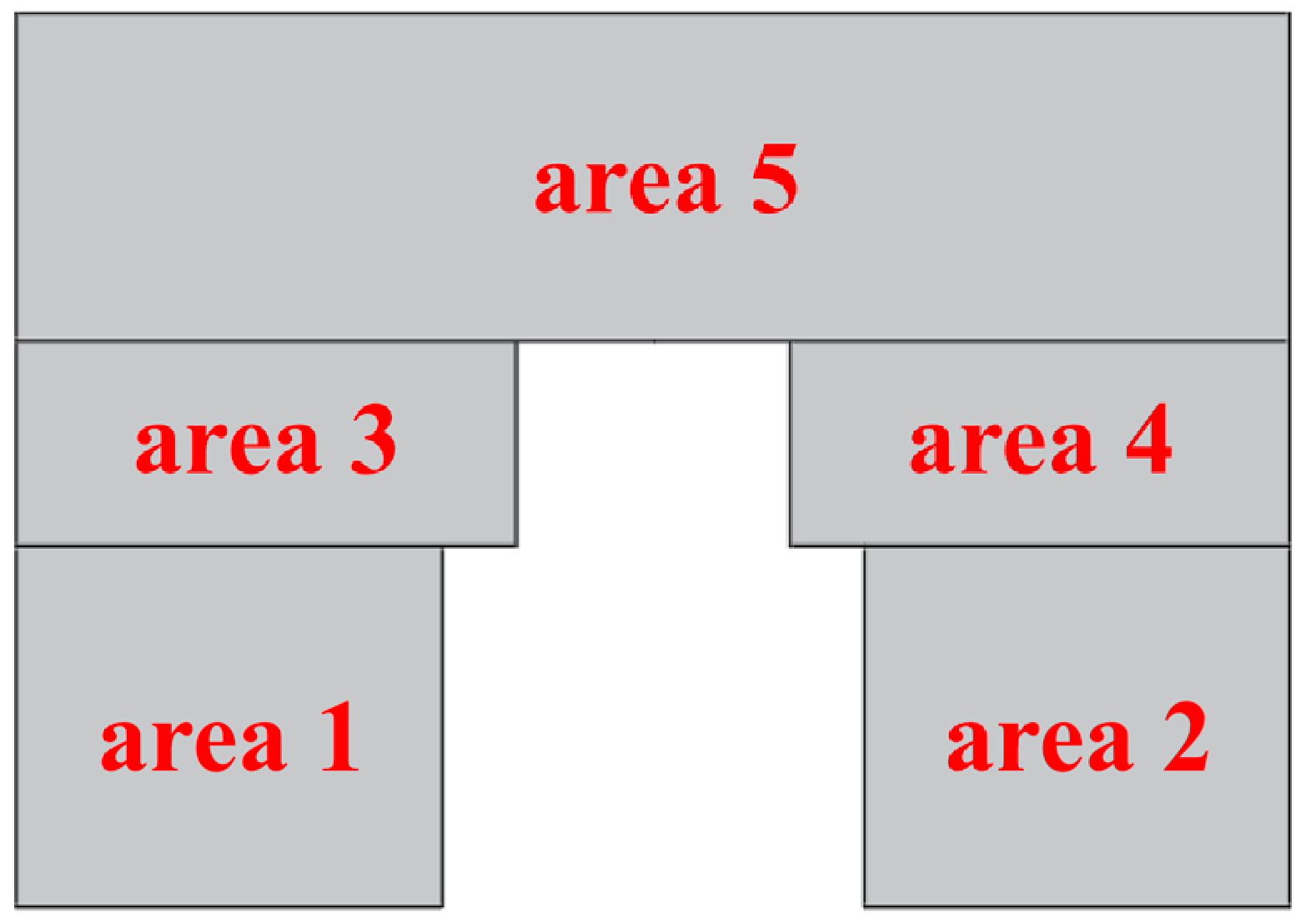
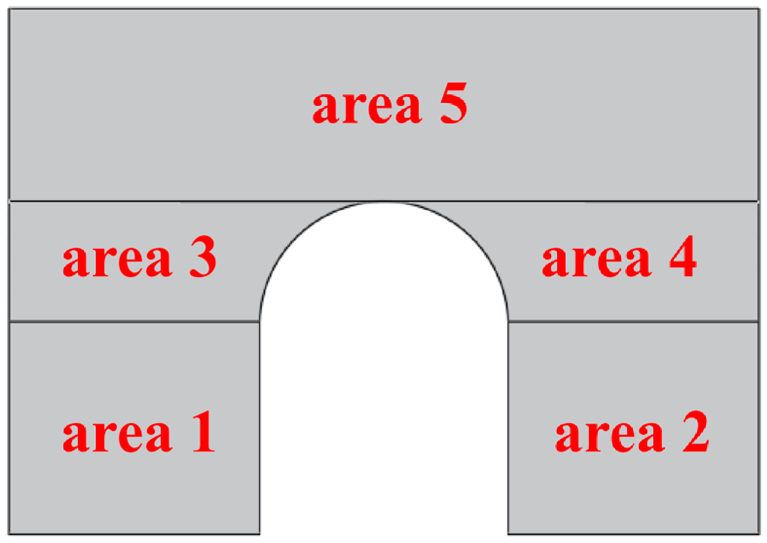
The ancient pagoda wall with openings is divided into five parts, as shown in Figure 1. The shapes of areas 1, 2, and 5 are regular. The stiffness can be calculated using the stiffness calculation method for the wall without opening. The shapes of areas 3 and 4 are irregular, but they can be simplified to regular shapes using the equivalent-area method. The upper part of the opening is assumed to be a semicircle. Before simplification, the length and height of area 3 are l and h, respectively; after simplification, they become le and he.
The simplification of the ancient pagoda wall is illustrated in Figure 2.
he = h
l e = l + 4 π 4 h
The stiffness values of areas 1, 2, 3, 4, and 5 are K1, K2, K3, K4, and K5, respectively. The lateral stiffness of each wall segment along the transverse direction can be summed.
K 1 + 2 = K 1 + K 2
K 3 + 4 = K 3 + K 4
Equations (12) and (13) can be obtained from the reciprocal relationship between stiffness and flexibility.
δ 1 + 2 = 1 K 1 + K 2
δ 3 + 4 = 1 K 3 + K 4
The displacement at the top of the wall under the action of unit force is the sum of the displacement at the top of each segment after vertical division. Thus, Equation (14) can be derived.
δ = δ 1 + 2 + δ 3 + 4 + δ 5
δ = ( K 3 + K 4 ) K 5 + ( K 1 + K 2 ) K 5 + ( K 1 + K 2 ) ( K 3 + K 4 ) ( K 1 + K 2 ) ( K 3 + K 4 ) K 5
Equation (16) can be obtained according to the reciprocal principle of stiffness and flexibility.
K = ( K 1 + K 2 ) ( K 3 + K 4 ) K 5 ( K 3 + K 4 ) K 5 + ( K 1 + K 2 ) K 5 + ( K 1 + K 2 ) ( K 3 + K 4 )
The elastic stiffness of the ancient pagoda wall with an opening can be calculated by Equation (14). The length, height, and thickness of the ancient pagoda wall are 1870 mm, 1310 mm, and 370 mm, respectively. The aspect ratio is 0.7005. The length and height of the opening are 310 mm and 440 mm. The calculated elastic stiffness of the ancient pagoda wall is 66.85 kN/mm. The elastic stiffness of the ancient pagoda wall, calculated using the opening reduction method, is 66.07 kN/mm. The calculation results of the two methods are relatively close. Only the stiffness reduction due to the opening rate (ignoring the opening position) can be considered for the ancient pagoda wall when the opening reduction method is adopted. The elastic stiffness of the ancient pagoda wall obtained from the test is 71.04 kN/mm, and the gap between predicted and test data is 5.90%. For the second case, the wall dimensions remain the same (1870 mm × 1310 mm × 370 mm, aspect ratio 0.7005), but the opening dimensions are 660 mm and 880 mm. The calculated and experimental elastic stiffness values are 45.03 kN/mm and 49.18 kN/mm, respectively. The gap between predicted and test data is 8.44%, indicating that the formula can efficiently evaluate the elastic stiffness of ancient pagoda walls with openings.
The stiffness of the ancient pagoda wall with a crack is calculated according to the flexibility method. An ancient pagoda wall with a crack is divided into several wall panels, as shown in Figure 3. The calculation is performed according to the same principles as those for the ancient pagoda wall with an opening.
The lateral stiffness of each wall section in the transverse direction of can be summed, as shown in Equation (17).
K 2 + 3 = K 2 + K 3
Equation (18) can be obtained from the reciprocal relationship between stiffness and flexibility.
δ 2 + 3 = 1 K 2 + K 3
The displacement at the top of the wall under the action of unit force is the sum of the displacement at the top of each segment after vertical division. Thus, Equation (19) can be derived.
δ = δ 1 + δ 2 + 3 + δ 4
δ = ( K 2 + K 3 ) K 4 + K 1 K 4 + K 1 ( K 2 + K 3 ) K 1 ( K 2 + K 3 ) K 4
Equation (21) can be obtained from the reciprocal relationship between stiffness and flexibility.
K = K 1 ( K 2 + K 3 ) K 4 ( K 2 + K 3 ) K 4 + K 1 K 4 + K 1 ( K 2 + K 3 )
Test results of ancient pagoda walls indicate that the walls exhibit different degrees of rotation. The wall is more prone to rotational deformation with the increase of the aspect ratio. Although the failure mode of the ancient pagoda walls is a shear failure, a certain rotation deformation exists throughout the loading process. The deformation mechanism of ancient pagoda walls is often attributed to shear deformation, while the rotation deformation mechanism is frequently overlooked due to the prominent shear failure characteristics. The horizontal cracks caused by rotational deformation tend to close under compression, and the crack width of the rotational deformation is smaller than that of the diagonal cracks, which also leads to the neglect of the rotational deformation mechanism.
To account for the influence of rotational deformation on the elastic–plastic stiffness of the ancient pagoda wall, a lateral stiffness calculation model is proposed by introducing rotational deformation. The elastic–plastic lateral stiffness theory of the ancient pagoda wall is modified. The aspect ratio and vertical stress are important factors affecting the rotational deformation of the wall. The aspect ratio and vertical stress are important factors affecting the occurrence and magnitude of the rotational deformation. The lateral stiffness of the wall is modified by incorporating the aspect ratio and vertical stress.
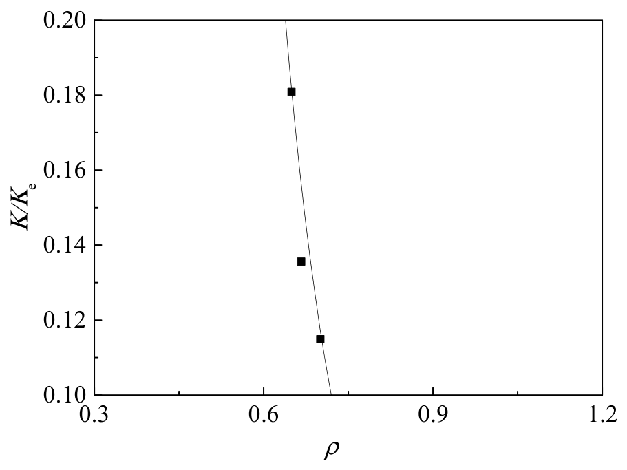
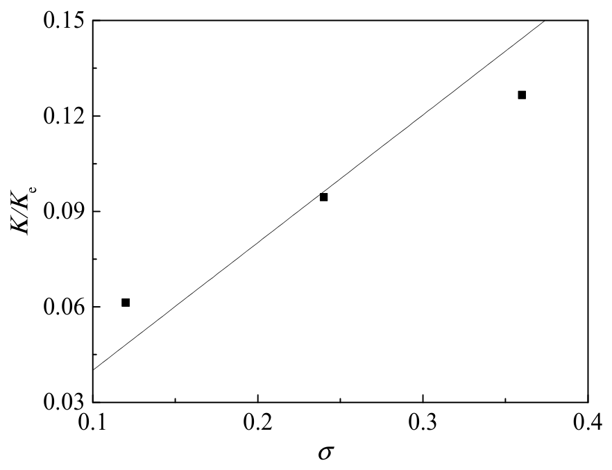
Based on the experimental results of the ancient pagoda wall (presented in Table 5) [35,36], the measured stiffness K and theoretical elastic stiffness Kc of each specimen are extracted, and the stiffness ratio η = K/Kc is taken as the vertical coordinate. The aspect ratio and vertical stress are taken as the horizontal coordinate for regression analysis. According to the variation law of test data, a function model is adopted for multivariate regression: η = a × σ × ρ b, where a, b are undetermined regression coefficients. The least squares method is used for regression fitting of all test data via MATLAB (vR2023b). The values of a and b are 0.1 and 0.2, respectively. The fitting results are shown in Figure 4 and Figure 5. The final elastic–plastic stiffness calculation formula is given in Equation (22).
K = 0.01323 σ ρ 9.584 K e

3.3. Calculation Method of Shear Bearing Capacity

The shear bearing capacity calculation method for an ancient pagoda wall without opening is shown in Equation (23).
V = f vm A
f vm = f v 0 + 0.65 σ 0
where A represents the ancient pagoda wall’s cross-sectional area; fvm represents the masonry’s shear strength subjected to combined stress; fv0 represents the masonry’s shear strength when no vertical load is applied; σ0 represents the vertical stress.
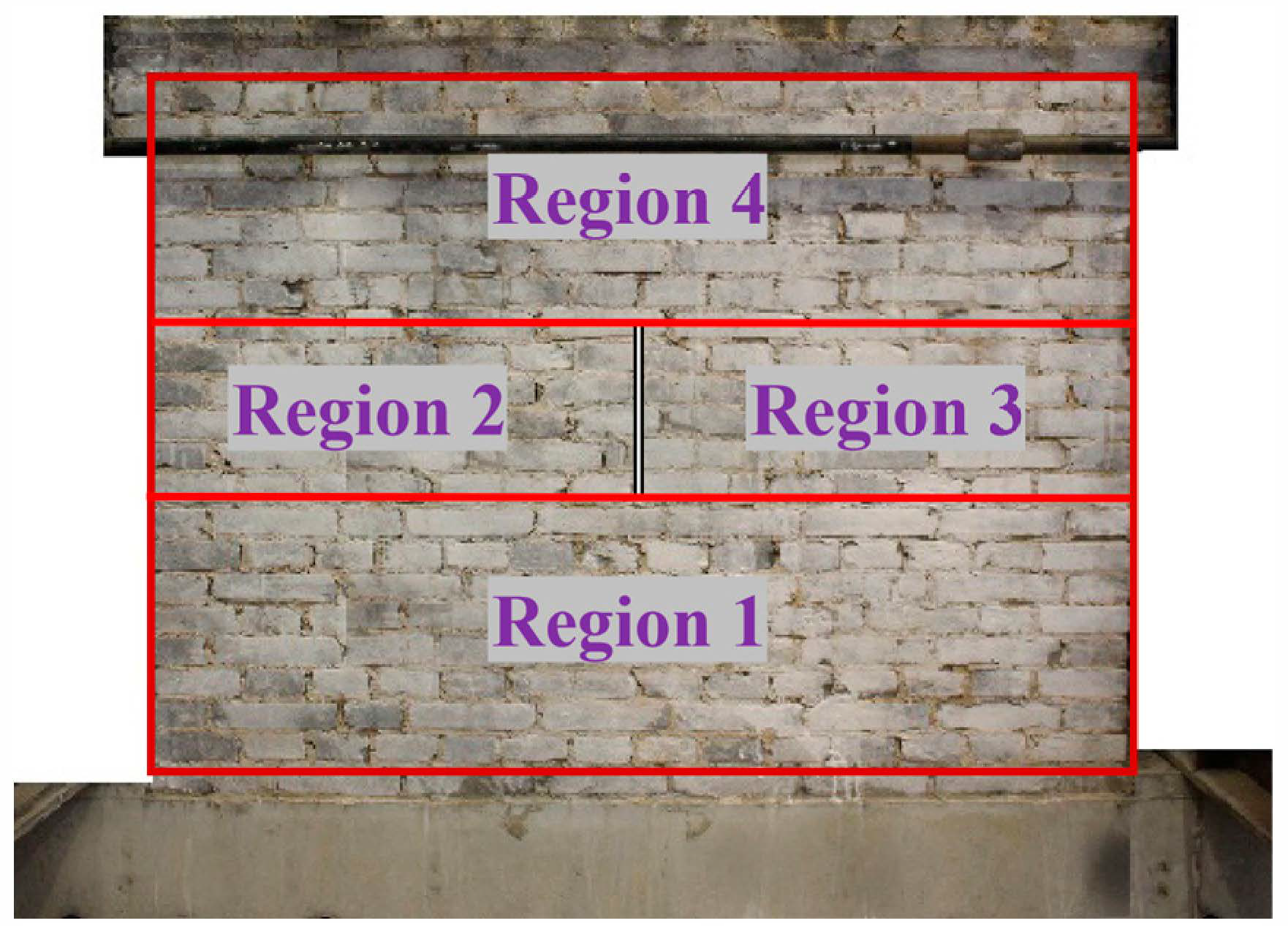
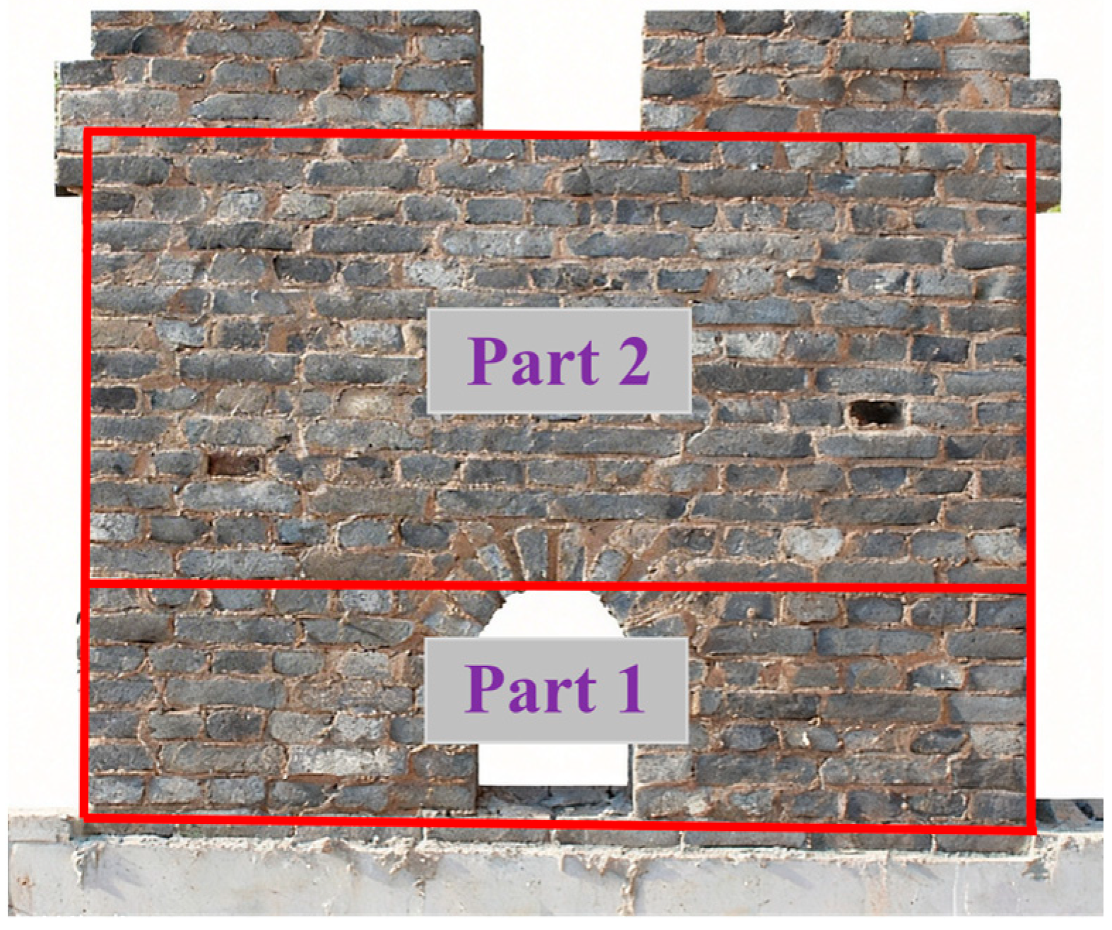
The shear bearing capacity calculation method for an ancient pagoda wall with an opening is expressed in Equation (25). The schematic diagram showing the division for an ancient pagoda wall with an opening is given in Figure 6.
V = h 1 h 1 + h 2 V 1 + h 2 h 1 + h 2 V 2
where V, V1, and V2 are the shear bearing capacities of the ancient pagoda wall with an opening, zone 1, and zone 2, respectively; h1 and h2 are the heights of the ancient pagoda wall in area 1 and area 2, respectively.
σ 1 = σ 2 + G 2 A 1
where σ1 and σ2 are the vertical stresses borne by region 1 and region 2, respectively; G2 is the self-weight of the wall in zone 2; A1 is the cross-sectional area of the wall in zone 1.
The shear bearing capacity calculation method for cracked ancient pagoda walls is presented in Equation (27).
V c = f v 0 + 0.65 4 σ l d + 2 ρ l d h ρ d d c l c 4 d ( l d c ) d ( l d c )
where l and lc are the lengths of the wall and crack, respectively; d and dc are the thickness of the wall and the width of the crack, respectively; h is the height of the wall; ρ is the density of the wall.
Cyclic seismic loading may induce bond slip and interface deterioration, which reduces the actual contribution from the GFRP bar to shear resistance. To address this issue, research on low-strength mortar NSM-FRP strengthened masonry structures has been carried out, and an interface bond reduction factor is proposed to correct the formula of shear bearing capacity, considering bar slip and possible anchorage failure.

4. Seismic Fortification Standard and Two-Stage Design Method

4.1. Seismic Fortification Objectives and Standards

The service life of the ancient pagodas is higher than that of ordinary buildings because ancient pagodas are cultural heritage sites. The fortification target for ancient pagodas should be higher than that for ordinary buildings. The fortification standard for ancient pagodas should exceed the local seismic fortification intensity requirements, and general seismic measures should be adopted as required for an intensity one degree higher. According to probabilistic statistical analysis, the seismic fortification intensity is about one degree higher than the local fortification intensity [39]. The high seismic fortification intensity can be regarded as a rare earthquake intensity, and the seismic fortification objectives of the ancient pagodas are defined as follows:
  • The first objective is generally to sustain no damage under seismic actions with intensity below the regional rare intensity.
  • The second objective is that the ancient pagoda can still be used after general reinforcement measures when it is subjected to seismic action with an intensity equivalent to the local rare earthquake.
  • The third objective is that no collapse or serious damage will occur under seismic action with an intensity exceeding the regional rare earthquake intensity.
To achieve the above seismic fortification requirements, a two-stage design method is proposed.
The first stage is to meet the requirements of the first seismic fortification objective through bearing capacity design and elastic deformation verification under seismic actions with intensity below the regional rare seismic intensity.
The second stage is to meet the requirements of the third seismic fortification objective through elastic–plastic deformation verification under seismic actions with intensity above the regional rare seismic intensity. The second seismic fortification objective is realized through detailing measures.
The detailing measures of the ancient pagodas with embedded GFRP bars are as follows:
  • The GFRP bars on both sides shall be tied with tie bars along the wall length, and the spacing of the tie bars shall not exceed 500 mm.
  • The spacing of embedded GFRP bars in the longitudinal direction shall not exceed five courses of bricks.
  • The diameter of the GFRP bars shall not exceed 3/5 of the mortar joint thickness.
  • The bond strength of the bonding mortar for embedded GFRP bars shall not be less than 3 MPa.
  • The embedment depth of the bonding mortar shall not be less than 40 mm.
The protection and strengthening of historical buildings must be carried out in accordance with the protection requirements for the ancient pagoda as a cultural relic. No interference is allowed: grooving should take place only on original mortar joints, to a depth and width no greater than the specified dimensions; no blind grooving, no random chiseling on brick faces. The face of the wall is protected as all GFRP bars and bonding mortar are kept inside the mortar joints so that no additional decoration or components can be attached to its surface, thus keeping the original shape and appearance. A medium-strength bonding mortar provides a temporary bond that can be reversed at any time by manually removing the embedded bars for later maintenance or another intervention, while leaving the historical bricks and mortar intact. Before construction, for the protection of original buildings, existing cracks and damaged sections must be marked and protected. Grooving and bar embedding should produce minimal vibration and impact against the wall. A staged approach of implementation (three stages) is recommended for construction. Before construction, wall crack detection, vertical stress and mortar quality must be fully assessed, and then walls can be divided into three categories: intact walls, cracked walls, and walls with openings, each assigned a separate reinforcement plan. Anti-dust and anti-collision protection should also be applied to prevent damage. The construction sequence of the groove, dust cleaning, mortar filling, and GFRP bar embedding is strictly controlled during on-site construction, with tight control over the spacing between bars, embedment depth, and arrangement of tie bars; real-time inspection ensures compliance with requirements for seismic design and protection of cultural relics. The strengthened pagoda is protected by regular safety inspection, post-construction curing and long-term monitoring. The bonding mortar is naturally cured to avoid rapid drying and cracking. Long-term deformation monitoring points are installed on key wall sections, and observations are carried out regularly.

4.2. Design Ideas

The following seismic design concept is proposed. The ancient pagoda wall with insufficient bearing capacity can meet the bearing capacity requirements by embedding GFRP bars in the mortar joint under seismic actions with intensity below the regional rare seismic intensity. This ensures that the ancient pagoda wall, with low bearing capacity, does not sustain damage. The elastic and elastic–plastic deformations of the ancient pagoda wall are verified to ensure that the ancient pagoda satisfies the required deformation limits at both stages.
The seismic design concept is realized through the following method. The ancient pagoda’s shear bearing capacity is improved by embedding GFRP bars, and its deformation is restrained by the embedded GFRP bars.

4.3. Design Process

The design process of the strengthened ancient pagoda is proposed. The specific design process is as follows:
  • The seismic shear force of each story under minor earthquakes is calculated using the modal superposition response spectrum method.
  • The elastic stiffness of each story of the ancient pagoda is calculated. The seismic shear force of each story of the ancient pagoda is distributed according to the elastic stiffness.
  • The shear bearing capacity of each story is calculated using the prescribed method, taking into account vertical stress and opening rate.
  • Based on the seismic shear force and shear bearing capacity calculation results for ancient pagoda walls, the ancient pagoda’s weak parts are determined. The GFRP bar section design is carried out for the ancient pagoda wall with insufficient bearing capacity under seismic actions with intensity below the regional rare seismic intensity. The design of strengthening detailing measures is carried out.
  • After verifying the elastic and elastic–plastic inter-story deformations of the strengthened ancient pagoda, go back to step (4) if they fail to meet the requirements.
  • The final seismic retrofitting design parameters of the strengthened ancient pagoda are determined.
  • A systematic design and technical scheme on seismic retrofitting of ancient pagodas can be developed based on the above seismic reinforcement results, heritage conservation measures, and construction implementation strategies.

5. Example Analysis

5.1. Bearing Capacity Design

The 1/8 scale model of the Xiaoyan Pagoda is used in the example. The story masses and calculated heights of the model are given in Table 5. This test adopts the Cauchy similitude criterion for the seismic model test of a masonry structure. The seismic simulation test was carried out on a shaking table test system (MTS Systems Corporation, Eden Prairie, MN, USA). Based on the shaking table’s bearing capacity and size, the geometric scale ratio is selected as 1/8. We modified the material mechanical parameters and applied counterweights according to the similitude relations, thereby eliminating any deviation in self-weight stress, shear resistance, or overturning resistance due to geometric scaling. The geometric scale is 1/8, the elastic modulus scale is 1/5, and the time scale is 1/3.5. Extra steel masses are symmetrically distributed in each storey to compensate for the low self-weight of the scaled model, thus making sure that the self-weight stress distribution is similar to that in the prototype. This arrangement will avoid any overestimation of shear capacity and overturning resistance due to scale effects, thus confirming the validity of the test results.
The density of brick masonry is taken as 1800 kg/m3, the elastic modulus is 465 MPa, and Poisson’s ratio is taken as 0.15. The constitutive model of brick masonry is shown in Equation (28). The density of GFRP bars is 2100 kg/m3, and their elastic modulus is 40,000 MPa. A linear-elastic model is adopted for GFRP bars because they have no obvious yield point.
σ f m = 1.47 ( ε ε m ) 0.47 ( ε ε m ) 3
where fm is the peak compressive stress; εm is the strain corresponding to peak compressive stress.
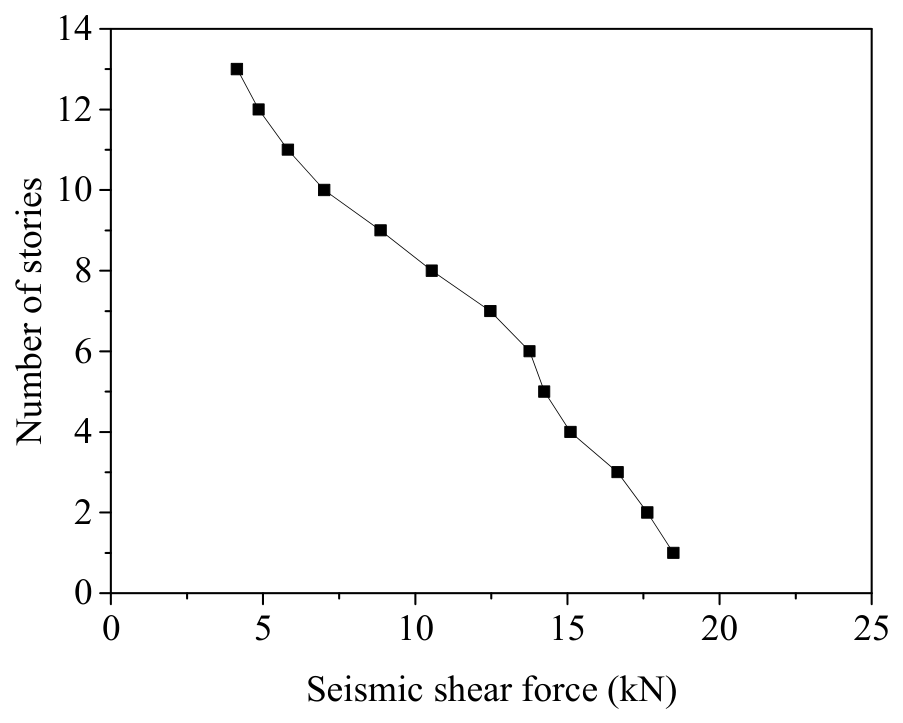
For the seismic shear force calculation of the ancient pagoda, the seismic fortification intensity is increased by one degree. The seismic shear force of the Xiaoyan Pagoda model is calculated by using the seismic fortification intensity of 9 degrees because Xiaoyan Pagoda’s regional fortification intensity is 8 degrees. The modal superposition response spectrum method is adopted for seismic shear force calculation. The calculation results are shown in Figure 7.
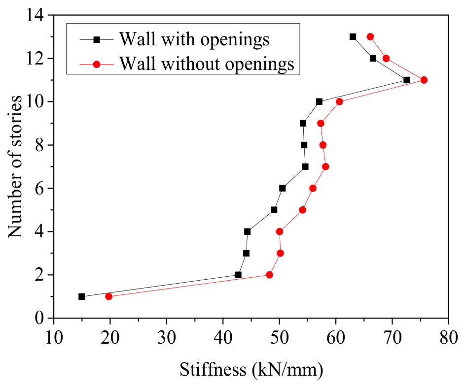
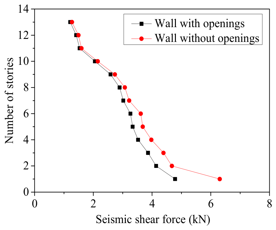
Each story of the ancient pagoda is approximated as a point mass. For each story of the ancient pagoda model, the seismic shear force is the sum of the seismic shear forces of two walls with openings and two walls without openings. The seismic shear force of the walls with and without openings differs. The seismic shear force of the walls with and without openings is distributed according to the walls’ stiffness. For each story of the ancient pagoda, the calculated stiffness of the walls with and without openings is described in Figure 8, and the seismic shear forces of the walls of the Xiaoyan Pagoda model are provided in Figure 9 and Table 6.
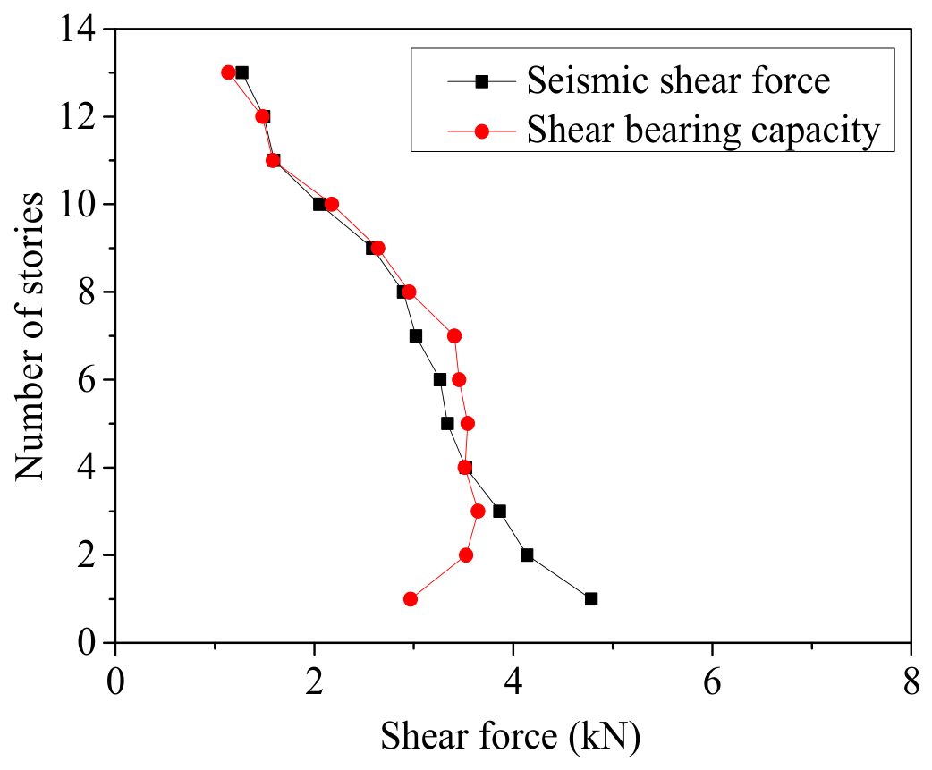
The shear bearing capacity and seismic shear force of the Xiaoyan Pagoda walls with openings are compared in Figure 10. The shear bearing capacity of the first to fourth stories and the eleventh to thirteenth stories does not meet the seismic shear force requirements, while the other stories do. Seismic retrofitting is required for the walls of the bottom four stories and the top three stories.
The shear capacity of historic brick masonry walls retrofitted with embedded GFRP bars consists of two main components: masonry shear capacity and horizontal GFRP bar shear capacity.
V u = V u 1 + V u 2
The shear capacity of horizontal GFRP bars follows Equation (18).
V u 2 = ζ f y A s
where ζ is the participation coefficient of GFRP bars; fy is the tensile strength of GFRP bars; As is the total horizontal and longitudinal GFRP bars area of the wall section.
The relationship between the GFRP participation coefficient of GFRP bars and vertical stress, aspect ratio is obtained through data fitting, as shown in Equation (31).
ζ = 0.95 σ [ 0.83 × ( H / L ) + 1.68 ]
According to Equations (29)–(31), the relationship among the area of embedded GFRP bars, the shear bearing capacity of both retrofitted and non-retrofitted ancient pagoda walls, the vertical stress, and the aspect ratio is shown in Equation (32). Based on the test result of eight ancient pagoda wall specimens and considering the weakness of historical lime mortar and cyclic seismic action, the bond reduction factor η is taken as 0.75~0.85. A conservative value η = 0.80 is used for the following calculation to prevent an overestimation of structural strength.
A s = V u V u 1 0.95 η σ 0.83 × ( H / L ) + 1.68
where As is the cross-sectional area of the embedded GFRP bars; Vu, Vu1 and Vu2 are the shear bearing capacities of the retrofitted and non-retrofitted ancient pagoda walls, and the shear capacity of horizontal GFRP bars, respectively; σ is the vertical stress on the ancient pagoda walls; H and L are the height and length of the ancient pagoda walls.
According to Equation (26), the areas of GFRP bars required to be embedded in the first to fourth stories of the ancient pagoda walls are 83.55 mm2, 12.69 mm2, 4.69 mm2 and 0.16 mm2, respectively. The areas of GFRP bars required to be embedded in the eleventh to thirteenth stories of the ancient pagoda walls are 0.26 mm2, 0.40 mm2 and 5.39 mm2.

5.2. Verification of Inter-Story Drift Angle

The elastic–plastic stiffness of the ancient pagoda walls is calculated using Equation (20), and the results are presented in Table 7.
The inter-story deformation of the Xiaoyan Pagoda structure can be calculated based on the seismic shear force and inter-story stiffness. The inter-story displacement angle equals the ratio of inter-story deformation to story height. Table 8 presents the calculation results.
The elastic and elastic–plastic maximum inter-story drift angles of the ancient pagoda model are 0.00005036 and 0.0064, respectively, which are below the prescribed limits of 1/1800 and 1/125, indicating that the deformation of the model meets the structural deformation requirements.

6. Conclusions

To address the issue that ancient pagodas are prone to damage and collapse due to aging materials and structural deterioration, this study focuses on the application of embedded GFRP bar technology for the seismic protection of ancient pagodas. A systematic investigation of the seismic design method based on the bearing capacity is conducted. The core technical points and design process are clarified through theoretical analysis, statistical analysis of test data, and example verification. The key conclusions include:
(1)
On the basis of the experimental statistical data of the ancient pagoda walls, the elastic and elastic–plastic inter-story drift angle limits for the ancient pagoda structure are determined. The elastic and elastic–plastic inter-story drift angle limits are suggested to be 1/1800 and 1/125, respectively.
(2)
For the calculation and distribution of seismic shear force, it is confirmed that the seismic shear force of the ancient pagoda is calculated using the modal superposition response spectrum method. Considering the rigidity characteristics of the floor, the seismic shear force of each floor is distributed to each lateral force-resisting wall according to the lateral stiffness ratio of the wall. The stiffness and shear bearing capacity calculation methods for ancient pagoda walls are established.
(3)
A two-stage seismic retrofitting design for ancient pagodas with embedded GFRP bars is proposed. The first stage consists of bearing capacity design and elastic deformation verification under seismic actions with an intensity lower than the local rare earthquake intensity. The second stage consists of elastic–plastic deformation verification under seismic actions with an intensity higher than the local rare earthquake intensity.
(4)
A design method for strengthening an ancient pagoda with embedded GFRP bars is proposed. The specific design process is given. The reinforcement design of the Xiaoyan Pagoda model with embedded GFRP bars is performed. The specific reinforcement scheme is provided, and the inter-story deformation is verified.

Author Contributions

Conceptualization, W.H. and Q.X.; methodology, W.H. and Q.X.; validation, W.H. and Q.B.; formal analysis, W.H.; investigation, W.H. and Q.B.; resources, Q.B.; data curation, W.H. and Q.B.; writing—original draft preparation, W.H.; writing—review and editing, W.H., Q.B. and D.X.; visualization, H.W. and X.F.; supervision, W.H. and Q.X.; funding acquisition, W.H., Q.X. and H.W. All authors have read and agreed to the published version of the manuscript.

Funding

The authors gratefully acknowledge financial support from the National Natural Science Foundation of China (Grant No. 52178303), the Science Fund for Distinguished Young Scholars of Shaanxi Province (Grant No. 2021JC-44), the General Project of Philosophy and Social Sciences Research in Jiangsu Education Department (Grant No. 2023SJYB1812) and Jiangsu Ocean University’s “Haizhou Bay Talents” Innovation Program Project (Grant No. KQ24041).

Data Availability Statement

The original contributions presented in this study are included in the article. Further inquiries can be directed to the corresponding authors.

Conflicts of Interest

The authors declare no conflicts of interest.

References

  1. Invernizzi, S.; Lacidogna, G.; Lozano-Ramírez, N.E.; Carpinteri, A. Structural monitoring and assessment of an ancient masonry tower. Eng. Fract. Mech. 2019, 210, 429–443. [Google Scholar] [CrossRef] [Scilit]
  2. Chu, Y.P.; Jiang, T.Y.; Tan, S.L.; Pu, G.Y. Static pushover investigation on the stability and failure mechanisms of ancient brick pagodas. Structures 2026, 84, 111049. [Google Scholar] [CrossRef] [Scilit]
  3. Wu, X.Q.; Lu, J.L.; Li, D.; Wang, Z.S.; Li, X.L.; Liang, G. Seismic response analysis of ancient masonry pagodas considering soil-structure interaction. J. Build. Eng. 2025, 107, 112719. [Google Scholar] [CrossRef] [Scilit]
  4. He, S.H.; Xiong, Z.; Mai, G.H.; Liu, F.; Li, L.J. Durability of fibre reinforced polymer bars served in marine environments: A systematic review and an improved life-prediction model. Constr. Build. Mater. 2025, 495, 143486. [Google Scholar] [CrossRef] [Scilit]
  5. Petersen, R.B.; Masia, M.J.; Seracino, R. In-plane shear behavior of masonry panels strengthened with NSM CFRP strips. I: Experimental investigation. J. Compos. Constr. 2010, 14, 754–763. [Google Scholar] [CrossRef] [Scilit]
  6. Petersen, R.B.; Masia, M.J.; Seracino, R. In-plane shear behavior of masonry panels strengthened with NSM CFRP strips. II: Finite-element model. J. Compos. Constr. 2010, 14, 764–774. [Google Scholar] [CrossRef] [Scilit]
  7. Dizhur, D.; Griffith, M.; Ingham, J. In-plane shear improvement of unreinforced masonry wall panels using NSM CFRP strips. J. Compos. Constr. 2013, 16, 04013010. [Google Scholar] [CrossRef] [Scilit]
  8. Dizhur, D.; Griffith, M.C.; Ingham, J.M. Pullout strength of NSM CFRP strips bonded to vintage clay brick masonry. Eng. Struct. 2014, 69, 25–36. [Google Scholar] [CrossRef] [Scilit]
  9. Dizhur, D.; Griffith, M.; Ingham, J. Out-of-plane strengthening of unreinforced masonry walls using near surface mounted fibre reinforced polymer strips. Eng. Struct. 2014, 59, 330–343. [Google Scholar] [CrossRef] [Scilit]
  10. Konthesingha, K.M.C.; Masiam, M.J.; Petersen, R.B.; Mojsilovic, N.; Simundic, G.; Page, A.W. Static cyclic in-plane shear response of damaged masonry walls retrofitted with NSM FRP strips-an experimental evaluation. Eng. Struct. 2013, 50, 126–136. [Google Scholar] [CrossRef] [Scilit]
  11. Konthesingha, K.M.C.; Masiam, M.J.; Petersen, R.B.; Page, A.W. Experimental evaluation of static cyclic in-plane shear behavior of unreinforced masonry walls strengthened with NSM FRP strips. J. Compos. Constr. 2015, 19, 04014055. [Google Scholar] [CrossRef] [Scilit]
  12. Griffith, M.C.; Kashyap, J.; Ali, M.S.M. Flexural displacement response of NSM FRP retrofitted masonry walls. Constr. Build. Mater. 2013, 49, 1032–1040. [Google Scholar] [CrossRef] [Scilit]
  13. Yu, P.Y.; Silva, P.; Nanni, A. Bond behavior of near-surface mounted FRP bars to masonry. J. Compos. Constr. 2018, 22, 04018024. [Google Scholar] [CrossRef] [Scilit]
  14. Hernoune, H.; Benabed, B.; Kanellopoulos, A.; Al-Zuhairi, A.H.; Guettala, A. Experimental and numerical study of behaviour of reinforced masonry walls with NSM CFRP strips subjected to combined loads. Buildings 2020, 10, 103. [Google Scholar] [CrossRef] [Scilit]
  15. GB50003-2011; Code for Design of Masonry Structures. Standardization Administration of the People’s Republic of China: Beijing, China, 2012.
  16. GB50011-2010; Code for Seismic Design of Buildings. Standardization Administration of the People’s Republic of China: Beijing, China, 2010.
  17. Ren, X.; Tao, Y. Discussion on the seismic design analysis method of masonry building. Adv. Mater. Res. 2010, 163–167, 3952–3957. [Google Scholar] [CrossRef] [Scilit]
  18. Porst, C.F.; Hart, T.; Ochsendorf, J. Confined masonry for resilient low-cost housing in India: A design and analysis method. In Proceedings of the 16th World Conference on Earthquake Engineering, Santiago, Chile, 9–13 January 2017; pp. 1–10. [Google Scholar]
  19. Zhou, Q.; Cheng, D.; Xiao, H.; Yu, T.Y.; Zhao, W.Y. Seismic performance analysis of masonry structure in typical villages and towns under mainshock-aftershock sequence ground motion. J. Nat. Disasters 2022, 31, 84–92. [Google Scholar] [CrossRef]
  20. Jiang, L.X.; Li, X.M.; Wang, Z.L.; Zhang, F.W. Discussion on performance-based seismic design and assessment methods of masonry structures. Struct. Eng. 2022, 38, 48–57. [Google Scholar] [CrossRef]
  21. Xu, D.F.; Xie, Q.F.; Hao, W.M. Seismic damage evaluation of historical masonry towers through numerical model. Bull. Earthq. Eng. 2024, 22, 2235–2266. [Google Scholar] [CrossRef] [Scilit]
  22. Najafgholipour, M.A.; Hamidian, Z.; Darvishi, H.; Gardoni, P. The failure assessment of historical masonry towers subjected to near-field and far-field ground motions. Eng. Fail. Anal. 2025, 180, 109856. [Google Scholar] [CrossRef] [Scilit]
  23. Li, Y.X.; Xu, D.F.; Gong, T.N.; Fan, J.H. A data-driven framework for seismic fragility and performance degradation assessment of historical masonry pagodas: Integrating multi-task machine learning and interpretable uncertainty quantification. Bull. Earthq. Eng. 2025, 23, 6653–6678. [Google Scholar] [CrossRef] [Scilit]
  24. Hadzima-Nyarko, M.; Ademovic, N.; Pavic, G.; Sipos, T.K. Strengthening techniques for masonry structures of cultural heritage according to recent Croatian provisions. Earthq. Struct. 2018, 15, 473–485. [Google Scholar] [CrossRef]
  25. Ferraioli, M.; Lavino, A.; Abruzzese, D.; Avossa, A.M. Seismic assessment, repair and strengthening of a medieval masonry tower in southern Italy. Int. J. Civ. Eng. 2020, 18, 967–994. [Google Scholar] [CrossRef] [Scilit]
  26. Jing, J.J.; Zhou, C.D.; Zhang, C.; Li, T. In-plane cyclic behavior of brick walls strengthened with CFRP plates embedded in the horizontal mortar joint. J. Build. Eng. 2022, 63, 105476. [Google Scholar] [CrossRef] [Scilit]
  27. Borzi, B.; Crowley, H.; Pinho, R. Simplified pushover-based earthquake loss assessment (SPBELTA) method for masonry building. Int. J. Archit. Herit. 2008, 2, 353–376. [Google Scholar] [CrossRef] [Scilit]
  28. Pasticier, L.; Amadio, C.; Fragiacomo, M. Non-linear seismic analysis and vulnerability evaluation of a masonry building by means of the SAP2000 V. 10 code. Earthq. Eng. Struct. D 2008, 37, 467–485. [Google Scholar] [CrossRef] [Scilit]
  29. Shahzada, K.; Khan, A.N.; Elnashai, A.S.; Ashraf, M.; Javed, M.; Naseer, A.; Alam, B. Experimental seismic performance evaluation of unreinforced brick masonry buildings. Earthq. Spectra 2012, 28, 1269–1290. [Google Scholar] [CrossRef] [Scilit]
  30. Ahmad, N.; Crowley, H.; Pinho, R.; Ali, Q. Displacement based earthquake loss assessment of masonry buildings in Mansehra City, Pakistan. J. Earthq. Eng. 2010, 14, 1–37. [Google Scholar] [CrossRef] [Scilit]
  31. Su, Q.W.; Liu, Y.H.; Zhao, S.C. Seismic performance of masonry buildings based on wall area. China Civ. Eng. J. 2010, 43, 473–478. [Google Scholar] [CrossRef]
  32. Xiong, L.H.; Wu, W.B.; Su, Y. Seismic performance of confined masonry buildings during the Wenchuan earthquake. China Civ. Eng. J. 2012, 45, 103–108. [Google Scholar] [CrossRef]
  33. FEMA 356; Federal Emergency Management Agency. Prestandard and Commentary for the Seismic Rehabilitation of Buildings: Washington DC, USA, 2000.
  34. Jiang, L.X.; Wang, Z.L.; Zhang, F.W. Damage degree and inter-story drift angle limit of multi-story masonry structures. J. Build. Struct. 2018, 36, 263–270. [Google Scholar] [CrossRef]
  35. Zhao, H.; Liu, W.; Yang, T.; Wang, S.L.; Li, B.B. Seismic performance test and finite element analysis of performance-enhanced ancient building masonry walls. Build. Struct. 2022, 52, 140–149. [Google Scholar] [CrossRef]
  36. Xie, Q.F.; Xu, D.F.; Wang, Y.Z.; Zhang, L.P.; Xin, R. Seismic behavior of brick masonry walls representative of ancient Chinese pagoda walls subjected to in-plane cyclic loading. Int. J. Archit. Herit. 2019, 15, 1336–1348. [Google Scholar] [CrossRef] [Scilit]
  37. Zhu, B.L.; Wu, M.S.; Jiang, Z.X. A study on seismic behaviour of concrete block masonry buildings and its strengthening by reinforced concrete columns. J. Build. Struct. 1984, 10, 32–46. [Google Scholar] [CrossRef]
  38. Feng, J.G.; Ba, R.G.; Fu, S.L. Experimental study on shear strength of unreinforced masonry walls under cyclic actions. J. Xian Inst. Metall. Constr. Eng. 1985, 41, 35–54. [Google Scholar] [CrossRef]
  39. Zhou, Y. Seismic Design of Building Structures; Wuhan University of Technology Press: Wuhan, China, 2021. [Google Scholar]
Figure 1. Schematic diagram of the division of an ancient pagoda wall with an opening.
Buildings 16 02468 g001
Figure 2. Schematic diagram of the simplified ancient pagoda wall.
Buildings 16 02468 g002
Figure 3. Schematic diagram of the division of an ancient pagoda wall with a crack.
Buildings 16 02468 g003
Figure 4. Fitting results of the aspect ratio.
Buildings 16 02468 g004
Figure 5. Fitting results of vertical stress.
Buildings 16 02468 g005
Figure 6. Schematic diagram of the division for the ancient pagoda wall with an opening.
Buildings 16 02468 g006
Figure 7. Seismic shear forces at each story of the Xiaoyan Pagoda model.
Buildings 16 02468 g007
Figure 8. Stiffness of walls at each story of the Xiaoyan Pagoda model.
Buildings 16 02468 g008
Figure 9. Seismic shear forces of walls at each story of the Xiaoyan Pagoda model.
Buildings 16 02468 g009
Figure 10. Comparison of seismic shear force and shear bearing capacity for walls with openings in the Xiaoyan Pagoda model.
Buildings 16 02468 g010
Table 1. Performance objectives and inter-story drift angle limits for masonry structures.
ReferencesResearch SubjectMinor Damage/Crack ControlSevere Damage/Life SafetyCollapse Control/Deformation Control
Borzi [27]Unreinforced masonry1/8001/3001/140
Pasticier [28]Unreinforced masonry1/14001/5001/330
Shahzada [29]Unreinforced masonry1/2500 (Immediate move-in)1/260 (Life safety)1/200
Ahmad [30]Unreinforced masonry1/1150 (Crack control)1/450 (Strength control)1/220 (Deformation control)
Su [31]Confined masonry1/25001/2001/150
Xiong [32]Unreinforced masonry1/850 (Minor damage)1/450 (Severe damage)/
Confined masonry1/800 (Minor damage)1/250 (Severe damage)/
FEMA 356 [33]Unreinforced masonry1/1000 (Immediate move-in)1/330 (Life safety)1/250
Confined masonry1/250 (Immediate move-in)1/160 (Life safety)1/130
Jiang [34]Unreinforced masonry1/800 (Minor damage)1/330 (Severe damage)/
Confined masonry1/800 (Minor damage)1/300~1/165 (Severe damage)/
Table 2. Comparison of inter-story drift angle limits for masonry structures.
NumberWall TypeWall Dimensions (mm × mm × mm)Inter-Story Drift Angle Limits
Q-1Unreinforced wall2000 × 1000 × 2401/63
Q-2Embedded bar reinforced wall1/54
Q-3Embedded bar reinforced wall1/53
Q-4Unreinforced wall3000 × 2100 × 3701/204
Q-5Embedded bar reinforced wall1/174
Q-6Unreinforced wall1200 × 2100 × 3701/186
Q-7Embedded bar reinforced wall1/146
Table 3. Inter-story drift angle.
Specimen NumberInter-Story Drift Angle at the Elastic Limit PointMeanInter-Story Drift Angle at the Elastic–Plastic Limit PointMean
W10.0005700.0006260.0083970.008027
W20.0006160.009485
W30.0006340.007274
W40.0006460.009854
W50.0004860.008469
W60.0008690.008187
W70.0008610.008567
W80.0003280.003982
Table 4. Masses and calculated heights of each story of the 1/8 scale model of the Xiaoyan Pagoda.
Number of StoriesMass Mi (t)Calculated Height
Hi (mm)
Number of StoriesMass Mi (t)Calculated Height
Hi (mm)
13.016427.580.8193403.5
21.5531089.590.6793700.5
31.4771538.5100.5193967
41.3851962110.3604191.5
51.2822364120.2494388
61.1382739130.2014574.5
70.9403085
Table 5. Main parameters of wall specimens.
Specimen NumberLength (mm)Height (mm)Thickness
(mm)
Opening Size
(mm × mm)
Vertical Stress
(MPa)
W118701310370/0.24
W218701310370310 × 4400.12
W318701310370310 × 4400.24
W418701310370310 × 4400.36
W518001200240/0.2
W617401130240/0.222
Table 6. Calculation results of the shear capacity of walls on each story of the Xiaoyan Pagoda model.
Number of StoriesVertical Stress (MPa)Opening Ratio (%)Shear Bearing Capacity (kN)
10.08420.092.97
20.0699.563.53
30.06210.003.65
40.0549.503.51
50.0467.783.54
60.0398.043.46
70.0335.153.41
80.0264.842.95
90.0214.532.64
100.0173.722.18
110.0113.071.58
120.00831.891.48
130.00412.271.14
Table 7. Calculation of elastic–plastic stiffness of walls per story for the Xiaoyan Pagoda model.
Number of StoriesVertical Stress (MPa)Aspect RatioInter-Story Elastic–Plastic Stiffness (kN/mm)
130.00410.4513.38
120.00830.4817.16
110.0110.4919.81
100.0170.575.85
90.0210.642.35
80.0260.691.46
70.0330.701.68
60.0390.750.95
50.0460.790.68
40.0540.860.35
30.0620.870.34
20.0690.910.23
10.0841.610.23
Table 8. Deformation verification.
Number of StoriesInter-Story Shear Force (kN)Inter-Story Elastic Stiffness (kN/mm)Inter-Story Elastic–Plastic Stiffness (kN/mm)Story Height
(mm)
Inter-Story Elastic Drift AngleInter-Story Elastic–Plastic Drift Angle
130.36126.0613.381690.000016900.000098
120.43133.2217.161930.000016710.00098
110.58145.1519.812000.000020050.00099
100.79114.105.852480.000028020.00049
90.96108.422.352850.000031020.0014
81.07108.761.463090.000031750.0024
70.22109.201.683280.000006240.0004
60.89101.080.953640.000024280.0026
50.9698.130.683860.000025430.0036
40.7788.650.354180.000020750.0053
30.6888.280.344290.000017910.0046
20.5585.430.234690.000013730.0049
11.2929.960.238550.000050360.0064
Disclaimer/Publisher’s Note: The statements, opinions and data contained in all publications are solely those of the individual author(s) and contributor(s) and not of MDPI and/or the editor(s). MDPI and/or the editor(s) disclaim responsibility for any injury to people or property resulting from any ideas, methods, instructions or products referred to in the content.