Abstract
The elastic support stiffness coefficient of opposing horizontal struts constitutes a critical parameter in the design of strutted retaining structures for deep excavations. The determination of the fixed-point adjustment coefficient serves as a fundamental prerequisite for the quantitative assessment of this stiffness coefficient. To identify the fixed-point location and establish a computational approach for , the endpoint displacements of opposing horizontal struts are classified into four distinct scenarios. For each scenario, the relationship between the lateral earth pressures on both sides of the excavation is derived, the support mechanism of the internal strut is elucidated, and the corresponding fixed-point locations of the struts are determined. Utilizing the response curve between the support-point displacement of the retaining structure and the lateral earth pressure, and adhering to the principle of linearization, analytical formulas for under the four scenarios are formulated. The proposed method is employed to compute and evaluate the fixed-point adjustment coefficient of the opposing horizontal struts in a case study drawn from the literature, with the results rigorously compared against the existing published data. Furthermore, the values for opposing horizontal struts in a metro station excavation project are computed and contrasted with values back-calculated from monitored horizontal displacements of the retaining structure. The findings demonstrate that the proposed method for determining is both computationally efficient and practically applicable. The derived values can be effectively used to predict internal forces and deformations in retaining structures for asymmetrically loaded deep excavations. This research offers substantial theoretical insights and practical implications for the scientifically informed design and construction of deep excavation support systems.
1. Introduction
In deep excavation engineering, the elastic foundation beam method is used to analyze the internal forces and deformations of strutted retaining structures. Within this framework, the elastic support stiffness coefficient of internal struts (), alongside the coefficient of the subgrade reaction, is a pivotal design parameter. The accuracy of directly governs the reliability of the structural analysis outcomes. While substantial research exists concerning the subgrade reaction coefficient [1,2,3,4,5,6,7], methodologies for determining remain comparatively underdeveloped and inconsistent [8,9,10,11].
For the most common opposing horizontal strut system (Figure 1a), the Technical Specification for Retaining and Protection of Building Foundation Excavations (JGJ 120-2012, hereafter “the Specification”) defines as (Equation (1)) [12]
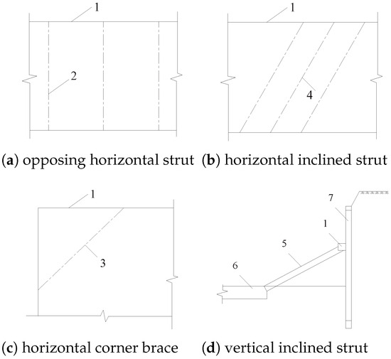
Figure 1.
Common types of internal struts. 1. Waist beam or capping beam; 2. opposing horizontal strut; 3. horizontal corner brace; 4. horizontal inclined strut; 5. vertical inclined strut; 6. vertical inclined strut foundation; 7. retaining element.
In this equation, represents the fixed-point adjustment coefficient. This critical parameter, defined conceptually as a ratio that governs how the total compressive deformation of a strut is distributed between its two endpoints, fundamentally influences the calculated stiffness . The determination of is uniquely complex, as it depends not on fixed material properties but on the evolving distribution of lateral earth pressure around the excavation during construction [12].
1.1. The Problem of Under Asymmetric Loading
In practice, a significant number of foundation pits are subjected to asymmetric loading conditions due to unbalanced surcharges, varying excavation depths, or staged construction sequences [5,13,14,15,16,17,18,19,20,21]. Under such conditions, the inward displacements of the two retaining walls are unequal (), causing the strut’s point of zero relative displacement (the fixed point) to shift away from the strut’s midspan. Consequently, the adjustment coefficients for the two sides also become unequal ().
The Specification acknowledges this asymmetry but provides only limited guidance. For perfectly symmetrical conditions (Scenario 1), it stipulates . For cases of moderate eccentric loading (Scenario 2), it states that falls within a range of 0.5 to 1.0, without providing a specific, mechanics-based calculation method [12].
1.2. The Critical Research Gap: Severe Asymmetry and Evolving Strut Mechanisms
More critically, both the Specification and the existing analytical literature [22,23,24,25,26,27,28] fail to address the mechanical behavior of struts under severe asymmetric loading. When the imbalance of lateral earth pressures exceeds a certain threshold, the displacement pattern at the strut endpoints can transition into more complex modes: one endpoint may displace inward while the other remains stationary (Scenario 3), or one may displace inward while the other moves outward (Scenario 4). In these scenarios, the conventional model of the strut as a simple axial spring (elastic support) may no longer be valid, and the fundamental support mechanism itself can change. The absence of a clear criterion to identify these scenarios and a unified method to determine across all of them represents a significant research and practical gap.
1.3. Research Objective and Contributions
This gap creates a dilemma for designers: applying the elastic foundation beam method to asymmetrically loaded excavations requires a value for , yet a comprehensive physics-based framework to determine it is lacking. To bridge this gap, this study pursues the following objectives:
- (1)
- To establish a clear earth pressure-based criterion for classifying the endpoint displacement of opposing horizontal struts into four distinct scenarios, covering the full spectrum from symmetry to severe asymmetry.
- (2)
- To elucidate the evolving support mechanism of the strut across these scenarios, clarifying its role when it ceases to function as a conventional elastic support.
- (3)
- To develop a unified analytical formula for calculating the fixed-point adjustment coefficient that is applicable to all four identified scenarios.
- (4)
- To validate the proposed method through comparative case studies against the published theoretical results and field monitoring data, demonstrating its generality and engineering reliability.
The outcomes of this work provide a rigorous theoretical foundation and a practical computational tool for the rational design of strutted retaining systems in complex asymmetrically loaded deep excavations. The formal definitions of the parameters, a detailed mechanical analysis, and case study applications are presented in the subsequent sections.
2. Problem Statement
2.1. Definition of the Adjustment Coefficient for Fixed Points in Opposing Horizontal Struts
As shown in Figure 2a, an opposing horizontal strut z–y of length is installed between the two retaining structures prior to excavation. As the excavation then proceeds downward, and the excavation face is gradually lowered, the retaining structures undergo horizontal displacement toward the excavation zone, as shown in Figure 2b. The internal strut z–y acts to restrain this displacement. At the support points z and y, which are also the endpoints of the strut, the deformation compatibility is maintained between the retaining structures and the strut.
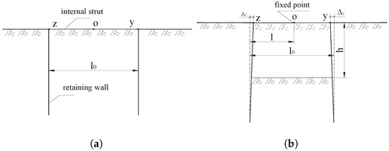
Figure 2.
Strutted retaining structure for a deep foundation pit. (a) Installation of z–y strut. (b) Excavation of the foundation pit to depth h.
As the excavation progresses from the condition depicted in Figure 2a to the depth h illustrated in Figure 2b, support point z displaces rightward by , while support point y displaces leftward by . According to deformation compatibility conditions, the opposing horizontal strut z–y undergoes a total compressive deformation of resulting in a reduction of the internal strut length from the original to .
Although the opposing horizontal strut z–y undergoes compressive deformation as the retaining structures on both sides of the excavation move inwards, there must be a point within the strut that experiences no displacement relative to its pre-compression position. This point, known as the point of zero displacement or the fixed point, is denoted as point O in Figure 2.
Assuming the distance from endpoint z to this fixed point before compression is l, we define the adjustment coefficient for the z-side as . Consequently, the adjustment coefficient for the opposite y-side is defined as .
2.2. Analysis of the Support Mechanism of Opposing Horizontal Struts
For the excavation depicted in Figure 2, the retaining walls on both sides displace inward during the excavation process, allowing the opposing horizontal strut z–y to be idealized as a compressive spring. Its supporting function on the retaining structures can be simplified as an elastic support with relatively high stiffness, as illustrated in Figure 3. The mechanism of this support can be characterized by the stiffness coefficients and , which represent the relationship between the displacement of the internal strut endpoints and the corresponding axial force, as given by Equations (2) and (3).
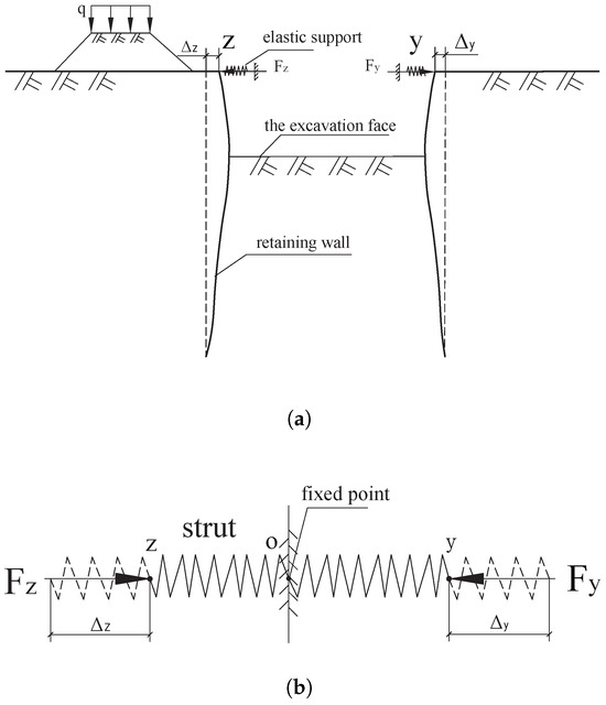
Figure 3.
Supporting effect of horizontal cross strut. (a) Elastic supports with high stiffness. (b) Compressive spring.
Figure 3b shows point O, which is the fixed point for the internal strut. Since the internal strut acts as a spring support, the endpoints z and y are consequently referred to as elastic support points. According to the equilibrium condition of the strut axial forces, where , the following relationship holds:
According to the definition of the adjustment coefficient for the fixed point in the strut, the following relationship holds:
It is evident that is closely related to the force and displacement conditions at the support points between the opposing horizontal strut and the retaining structure. Its magnitude reflects the distribution of the total compressive deformation of the opposing horizontal strut to the displacements at its endpoints. Therefore, it is termed the adjustment coefficient for the fixed point.
References [29,30,31,32,33] investigate the relationship between the displacement of the internal strut endpoints and the corresponding axial force. However, these studies do not address the quantitative relationship between the degree of asymmetric pressure on the excavation and the endpoint displacements, nor do they explore the calculation of .
During the design process, a value for must be estimated in advance. Based on this estimation, the force and displacement conditions at the support points are determined using Equations (1)–(3). Subsequently, the mechanical analysis of the retaining structure can be carried out by employing the Elastic Foundation Beam method.
2.3. Existing Issues in the Research on the Fixed-Point Adjustment Coefficient
2.3.1. Several Scenarios of Endpoint Displacement in Horizontal Cross Struts
In practice, the horizontal displacement of both retaining walls in Figure 2 toward the pit interior occurs only if the differences between the two sides of the excavation in terms of the soil properties, depth, peripheral loads, or construction sequence are within a specified limit. Regarding this prerequisite, the Specification provides an analysis for the following two primary scenarios:
Scenario 1: When the soil properties, depth, and peripheral loads on both sides are similar, and excavation is conducted in a symmetrical layered manner, the following conditions hold: , and .
Scenario 2: When the foundation pit is subjected to an eccentric load (e.g., from a surface surcharge on the left side, as shown in Figure 4), the horizontal strut displacement at the more heavily loaded side will be larger (i.e., ). In this case, ranges from 0.5 to 1.0, while , ranging from 0 to 0.5. However, the Specification does not stipulate a specific method for calculating the values in Scenario 2.
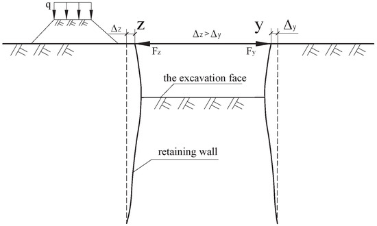
Figure 4.
Endpoint displacements in Scenario 2.
When the magnitude of eccentric loading on the foundation pit exceeds that defined in Scenario 2, Scenarios 3 and 4 may occur [34,35,36]. Scenario 3 is characterized by the displacement of one strut endpoint toward the pit interior, while the displacement of the opposite endpoint is zero, as shown in Figure 5a. Scenario 4 involves one endpoint displacing inward and the other endpoint displacing outward, as shown in Figure 5b. For these two more complex conditions, the Specification does not provide relevant analysis or conclusions.
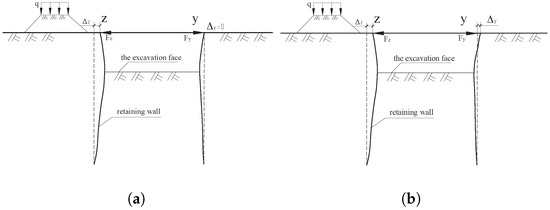
Figure 5.
Scenarios of endpoint displacements. (a) Endpoint displacements in Scenario 3. (b) Endpoint displacements in Scenario 4.
2.3.2. Issues Associated with the Adjustment Coefficient for the Fixed Point
Based on the foregoing analysis, the following key issues regarding the opposing horizontal struts in braced retaining structures still need to be resolved:
- (1)
- The primary issue is defining the displacement scenario of the strut endpoints. The displacement scenario is directly related to the degree of eccentric loading on the pit, which can be assessed by comparing the lateral earth pressures on opposite sides of the excavation. Therefore, comparing these lateral earth pressures presents a feasible methodology for determining the applicable displacement scenario.
- (2)
- Although the Specification and the existing literature [22,23,24,25] simplify the opposing horizontal strut in Scenarios 1 and 2 as elastic supports, providing their spring constraint stiffness on the retaining structures (Equations (1)–(3)), the mechanical mechanism of the strut in Scenarios 3 and 4 remains unclear, constituting a research gap.
- (3)
- Regarding the determination of the value, the Specification stipulates a value of 0.5 for both and in Scenario 1, which is widely accepted and applied [26,27,28]. For Scenario 2, only a value range is given without a specific calculation method, while Scenarios 3 and 4 are not addressed at all. Consequently, establishing a unified method for calculating the value applicable to all four scenarios is a crucial prerequisite for the scientific design of strutted retaining structures.
3. Mechanical Analysis of Strutted Retaining Structures in Foundation Excavations
3.1. Mechanical Assumptions for Strutted Retaining Structures in Foundation Excavations
To capture the main contradiction of the problem, the following assumptions are made for the calculation of the strutted retaining structures of foundation excavations, with the mechanical model shown in Figure 6.
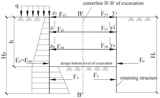
Figure 6.
Mechanical model of a strutted retaining structure in a deep foundation pit.
Assumption one: The design excavation depth of the foundation pit is h (m), with an identical soil layer distribution around its perimeter. The key soil properties—including the unit weight , the internal friction angle , and cohesion —are generalized as weighted averages over the depth of the retaining structure.
Assumption two: For a foundation pit subjected to eccentric loading, regardless of the cause, it is idealized as the condition shown in Figure 6, where a uniform surcharge is applied on the left ground surface relative to the right side. If , the condition is considered to be a symmetrically loaded excavation.
Assumption three: The depths of the left- and right-side retaining structures are and , respectively. When the earthwork is excavated to the designed pit bottom elevation, n levels of horizontal cross struts are installed vertically. The support forces provided by these struts are and for the left and right sides, respectively. The horizontal spacing between the struts is .
Assumption four: The lateral earth pressures acting on the left-side and right-side retaining structures, induced by unloading due to excavation inside the pit, are denoted as and , respectively. Similarly, the internal lateral earth pressures are denoted as and .
Assumption five: Due to the potential surcharge on the left side of the excavation relative to the right side, the magnitude of is considered the active lateral earth pressure . All active and passive lateral earth pressures are calculated based on Rankine’s earth pressure theory.
3.2. Mechanical Analysis of the Retaining Structure During Construction
If the installation of each level of struts and the excavation of the soil layer beneath it are defined as one construction step, then any step involves the installation of the opposing horizontal strut – and the excavation of soil with a thickness of –, where and represent the excavation depths (m) at construction steps and i, respectively. The computational schematic is shown in Figure 7. Accordingly, the excavation process illustrated in Figure 6, which involves the installation of n levels of struts and reaches the final design elevation, which undergoes a total of n construction steps.
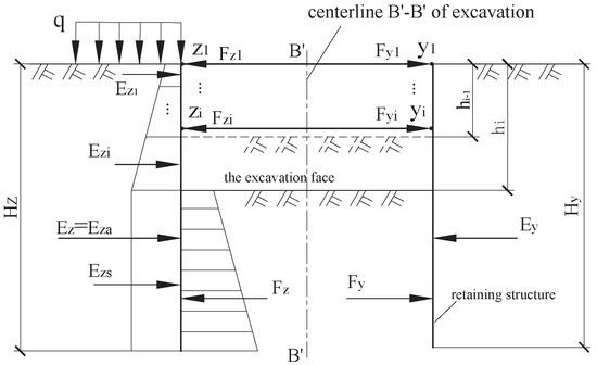
Figure 7.
Simplified model for the i-th construction stage.
Taking the retaining structure, the soil inside the pit, and the internal strut in Figure 7 as an integrated system, the foundation pit at the i-th construction stage is subjected to external lateral earth pressures and from both sides, satisfying the equilibrium condition given by Equation (9).
The excavation of each soil layer within the pit essentially unloads the corresponding magnitude of soil resistance (from the in-pit soil) on the retaining structure, which equivalently imposes an increment of active lateral earth pressure from the external soil. To model this mechanism, and can be decomposed into the earth pressure components above and below the excavation level, as specified in Equations (10) and (11).
and represent the external lateral earth pressures acting on the left and right retaining structures, respectively, within the depth range from to , after the completion of the i-th construction stage. and denote the components of the external lateral earth pressure below the excavation level acting on the left and right retaining structures, after the completion of the i-th construction stage.
If we consider the left retaining structure, internal strut, in-pit soil mass, and right retaining structure as separate free bodies and conduct force analysis on them, the following equilibrium equations can be established according to the equilibrium conditions:
Yao and Lin (2012) [37] observed through monitoring internal strut axial forces that the increase in the strut force is primarily induced by the excavation of soil layers immediately below the specific strut level. The installation of subsequent struts and the excavation of soil beneath them have a negligible influence on the axial force of the current strut. Similarly, Zhang et al. (2014) [38] showed that strut removal causes an abrupt change in the axial force of the upper strut, with limited impact on the other struts. Based on the empirical findings from Yao and Lin (2012) [37] and Zhang et al. (2014) [38], which indicate that the increment in the external lateral earth pressure on the retaining structure induced by soil excavation at each construction stage is entirely resisted by the horizontal struts installed during that corresponding stage, the following relationship can be established:
Based on this, if the magnitude and nature (active/passive) of and can be precisely determined, it becomes feasible to analyze the stress state and compressive deformation of each horizontal cross strut.
4. Study on the Fixed Points of Opposing Horizontal Struts
4.1. Determination of Endpoint Displacements for Opposing Horizontal Struts
Theoretical studies have demonstrated that the magnitude and distribution of earth pressures acting on the foundation pit support structures are not only related to the soil properties but also depend on factors such as the displacement direction, displacement magnitude, deformation mode of the retaining system, and the soil–structure interaction [39,40,41,42].
Among these factors, the direction and magnitude of the retaining structure’s displacement determine the nature (active or passive) and magnitude of the resulting lateral earth pressure. The lateral earth pressure acting on the wall is not a constant value; it varies with the amount of displacement. The relationship between them is shown in Figure 8 [43].
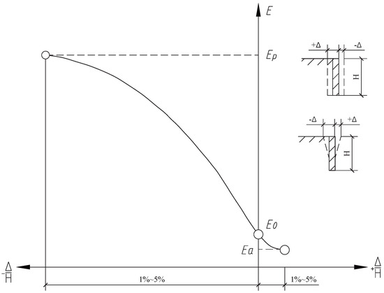
Figure 8.
Relationship between lateral earth pressure and retaining structure displacement.
The lateral earth pressures (E) at the three specific points on the curve— and —correspond to the at-rest earth pressure, active earth pressure, and passive earth pressure, respectively. Based on Figure 8 and considering the deformation compatibility conditions at the support points between the retaining structure and the horizontal cross struts, an analysis is conducted on the endpoint displacements of the horizontal cross strut – during construction stage
4.1.1. Scenario 1
If the environmental conditions, design parameters, and construction procedures on both sides of the foundation pit are relatively symmetrical (resulting in in Figure 7), then the corresponding earth pressures and during the i-th construction stage will satisfy Equation (17), and the horizontal endpoint displacements of the internal struts will conform to Scenario 1.
where and represent the active earth pressures on the external left and right sides within the depth range of to . When Equation (17) is satisfied, both the geometric dimensions and loading conditions of the foundation pit are symmetrical. According to the aforementioned assumptions and Figure 8, we have , which corresponds to Scenario 1.
4.1.2. Scenario 2
If differences exist in the environmental conditions, design parameters, or construction procedures on the two sides of the foundation pit, resulting in , as shown in Figure 7 (indicating an additional surcharge on the left side relative to the right), then . In this case, the magnitudes of and must be compared. If Equation (18) is satisfied, the horizontal endpoint displacements of the internal struts correspond to Scenario 2.
In this equation, represents the calculated value of the external at-rest earth pressure acting on the right retaining wall within the depth range to , upon completion of the i-th construction stage. Since and , Figure 8 indicates that both elastic support points of the i-th level internal strut displace inward into the excavation zone, with , thus corresponding to Scenario 2.
4.1.3. Scenario 3
When in the foundation pit of Figure 7, and the net unbalanced load from the external earth pressure exceeds the value given by Equation (18) and reaches that of Equation (19), the horizontal displacement at the endpoints of the internal strut falls under Scenario 3.
As can be seen from Figure 8, when the external earth pressure acting on the retaining structure equals the at-rest earth pressure, the displacement of the retaining structure is zero. Therefore, the displacement at the left endpoint of the i-th internal support () is directed toward the excavation zone, while the displacement at its right endpoint () is zero, satisfying the conditions for Scenario 3.
4.1.4. Scenario 4
If in the foundation pit shown in Figure 7, and the degree of asymmetry in the external earth pressure further increases until it reaches the value specified in Equation (20), then the displacement at the endpoints of the internal struts falls under Scenario 4.
In this equation, represents the calculated value of the external passive earth pressure on the right-side retaining structure within the depth range from to , after the completion of the i-th construction stage. When the external earth pressure lies between the at-rest earth pressure and the passive earth pressure, Figure 8 indicates that the retaining structure displaces away from the pit. Therefore, the displacement at the left endpoint of the i-th internal strut () is directed toward excavation zone, while the displacement at its right endpoint () is directed outward. Both the left and right endpoints of the internal strut displace rightward, thus satisfying the conditions for Scenario 4.
is the outward displacement of the right-side retaining structure caused by its deformation. According to the deformation compatibility condition, this also induces a rigid body displacement of at the strut’s right end. Consequently, comprises the strut’s own axial shortening () and this rigid body displacement (); i.e., .
4.1.5. Discussion
Note that the scenario described by Equation (21) does not exist.
Both and represent earth pressures under a state of limit equilibrium. The occurrence of the scenario described by Equation (21) would imply that the external soil mass on the right side of the foundation pit has either undergone compressive failure or is on the verge of such failure, which is a situation that is implausible in engineering. As can be observed from Figure 8, the displacement required to mobilize passive earth pressure is significantly larger than that for active earth pressure. Such substantial displacement is generally unacceptable in conventional construction projects. In practice, the retaining structure itself is likely to fail prematurely before the external soil mass reaches a state of failure [43].
4.2. Support Mechanism and Fixed-Point Locations of Opposing Horizontal Struts
4.2.1. Scenarios 1 and 2
The support mechanisms of opposing horizontal struts for Scenarios 1 and 2 have been provided by Equations (1)–(3) and Figure 3.
In Scenario 1, from and , the position of the fixed point is at the midpoint of the opposing horizontal strut, which also lies on the excavation centerline , as shown in Figure 7.
In Scenario 2, due to , with and , the fixed point is located to the right of the pre-compression midpoint of the opposing horizontal strut, that is, to the right of the excavation centerline .
4.2.2. Scenario 3
For the opposing horizontal strut in Scenario 3, since its left endpoint was displaced inward by , its mechanical mechanism on the left retaining structure acts as an elastic support. Equations (1) and (2) remain applicable. However, as the displacement at the right endpoint , the mechanical mechanism of the internal strut on the right retaining structure functions as a roller support, as illustrated in Figure 9 for the strut when . A roller support implies an infinite stiffness in the horizontal direction, resulting in zero horizontal displacement. Consequently, Equations (1) and (3) are no longer applicable.
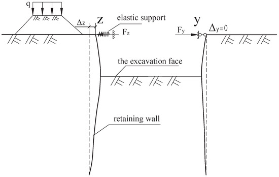
Figure 9.
The support mechanism of the internal strut for Scenario 3.
Except for the right endpoint, all other points of the internal strut undergo compressive deformation toward the right. The displacement of the left endpoint equals the amount of compressive deformation of the strut, while the right endpoint serves as the fixed point of the horizontal strut. According to Equations (7) and (8), we have and .
4.2.3. Scenario 4
For the opposing horizontal strut in Scenario 4, although both endpoints undergo displacement toward the right, only the compressive deformation of the strut itself provides the supporting effect, while the displacement caused by the rigid body motion contributes nothing. Since the displacement of the left endpoint includes deformation-induced displacement, the internal strut still acts as a support to the left retaining structure, functioning mechanically as an elastic support. Equations (1) and (2) remain applicable; however, in Equation (2), should be taken as the amount of compressive deformation rather than the total displacement .
For the right endpoint of the opposing horizontal strut, only the displacement caused by rigid body motion is present. Its mechanical action on the right retaining structure thus transitions into that of a load application, and Equations (1) and (3) are no longer applicable for the mechanical analysis of this right endpoint. In this case, the supporting effect on the right retaining structure is provided by the external soil resistance within the depth range from to , as illustrated in Figure 10 for the strut when . The corresponding external soil acts as a compressive spring, and the magnitude of the earth pressure lies between the at-rest earth pressure and the passive earth pressure.
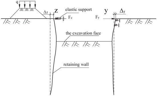
Figure 10.
The support mechanism of the internal strut for Scenario 4.
Although the right endpoint of the internal strut undergoes displacement due to rigid body motion, meaning its absolute position in the excavation space has changed, its position relative to other points on the strut remains unchanged. Therefore, the right endpoint still constitutes a fixed point, specifically, a relatively fixed point. According to Equations (7) and (8), we have and .
Jin and Liu (2019) [44] argued that, in certain scenarios, the internal strut does not possess a fixed point whatsoever. They recommend redefining the “support fixed-point adjustment coefficient ” as the “zero-deformation point adjustment coefficient ”. In practice, for cases where the internal strut undergoes rigid body motion, all points on the strut are displaced in terms of movement. Therefore, the fixed point of the strut should be regarded as a point with zero relative deformation (a deformation fixed point), rather than a point with zero absolute displacement (a displacement fixed point).
4.3. Calculation of the Fixed-Point Adjustment Coefficient for Opposed Horizontal Struts
Based on the above analysis results, the relationship curve between the retaining structure displacement and the lateral earth pressure in Figure 8 is linearized, leading to the quantitative calculation Formula (22) for the adjustment coefficient of the fixed point of the internal strut () at the i-th construction step, as shown in Figure 7.
Based on the previously stated mechanical assumptions for the excavation retaining and protection structure, and can be calculated using Equations (23) and (24), respectively. Furthermore, according to [43], is given by Equation (25).
where ; when , Equation (23) reduces to Equation (24), representing the case of an excavation under balanced earth pressure.
Substituting from Scenario 1 into Equation (22) yields ; substituting from Scenario 2 into Equation (22) gives a value between 0.5 and 1.0. For cases where and , the opposed horizontal strut falls under Scenarios 3 and 4, respectively, and Equation (22) indicates . Thus, the adjustment coefficient for the fixed point of the opposed horizontal strut under all scenarios during foundation excavation can be calculated using Equation (22).
5. Design and Application Examples of the Proposed Method
5.1. Design for Practical Application
To validate the generality, applicability, and reliability of the proposed method for calculating the fixed-point adjustment coefficient (), two distinct excavation support cases are selected and analyzed. These cases are detailed in Section 5.2 and Section 5.3, respectively.
The rationale for selecting these two examples lies in their representative differences in support system complexity and loading conditions, which allows for a comprehensive validation across different scenarios.
Case 1 (Section 5.2) represents a relatively shallow excavation with a single layer of horizontal struts. It is used to validate the method’s effectiveness in scenarios with simpler support configurations and significant asymmetric surcharge loads. The comparison focuses on the theoretical agreement with other established calculation methods.
Case 2 (Section 5.3) represents a deep excavation with multiple layers of horizontal struts (four levels). It serves to validate the method’s performance in complex multi-stage support systems typical of deep excavations. The comparison is more rigorous, involving back-analysis from field monitoring data to confirm the practical accuracy.
The primary differences, suitability for the theoretical work, and the scenarios they represent are summarized in Table 1 below. This table also lists the essential design parameters to facilitate the reader’s understanding of the application context.

Table 1.
Summary of application examples for method validation.
5.2. Case 1: Excavation with a Single Strut Layer
Figure 11 shows the example excavation from a reference, which was used to determine the fixed-point adjustment coefficient for opposing horizontal struts [45]. The figure provides the properties of the soil on both sides of the excavation and the supporting structures. Additional excavation details are as follows: The excavation is approximately rectangular in plan with length and width of 95 m and 38 m respectively, and an excavation depth of 10 m. A distributed load of 26 is applied on one side of the excavation top, while a construction load of 10 is applied on the opposite side. The support system consists of cast-in-place concrete piles with a single layer of opposing struts. The piles have a diameter of 1.2 m and are spaced at 1.4 m intervals. The struts are spaced horizontally at 7 m intervals with a cross-section of 1.1 m × 1.1 m. The concrete strength grade for the cast-in-place piles is C30.
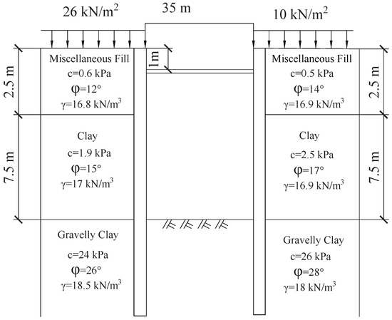
Figure 11.
Calculation diagram of fixed-point adjustment coefficient.
As shown in Figure 11, this case involves an excavation with a retaining structure supported by only a single layer of horizontal struts in the vertical direction. Based on the calculation rules provided in the text and the given parameters, values of , , and are obtained using Equations (23)–(25). Here, , which corresponds to the second scenario of endpoint displacement of an opposed horizontal strut. In this case, both retaining walls on the two sides of the excavation displace inward, and the position of the fixed point of the strut is located to the right of the centerline of the excavation.
Substituting , and into Equation (22) yields the corresponding adjustment coefficient for the fixed point of the opposed horizontal struts. A comparison between the calculated result and the value from reference [45] is presented in Table 2.
Table 2.
Calculation results of using different methods.
As can be seen from Table 2, the calculated adjustment coefficient for the fixed point on the overloaded side obtained by the proposed method is 0.671, while the values provided in reference [45] are 0.543 and 0.566, and the value in reference [46] is 0.733. The result from this study falls between those of references [45,46], indicating a more reasonable outcome.
As demonstrated by this case study, for any excavation subjected to eccentric loading—regardless of the cause—the proposed method can be readily applied to determine the earth pressure states on both sides of the excavation at each construction step, provided that the physical and mechanical parameters of the soil layers and the surrounding loads are known. Based on these results, the displacement scenario at the ends of the horizontal struts and the location of the fixed point can be identified, enabling the calculation of . The analytical method and calculation formulas presented in this study are characterized by clear mechanical principles and computational simplicity.
5.3. Example 2
To further validate the reliability of the proposed method, a standard section of a metro station foundation pit was taken as an example to calculate the fixed-point adjustment coefficient of the horizontal strut system. The results were then compared and analyzed against the value obtained through back analysis, which was based on the measured horizontal displacement at the ends of the internal struts.
The calculation cross-section is shown in Figure 12. This foundation pit represents a typical asymmetrical loading condition, with a surcharge of q = 60 applied on the left side. The excavation width is 19.6 m, and the depth is 17.1 m. The support system consists of diaphragm walls combined with internal struts. The diaphragm walls are 1.0 m thick, with depths of 33.6 m and 28.2 m on the left and right sides, respectively. A total of four levels of opposed horizontal struts are installed: the first level consists of 800 mm × 1000 mm (width × height) concrete struts, while the second to fourth levels use steel pipe struts measuring 609 mm × 16 mm. The horizontal spacing of the concrete struts is 8 m, and that of the steel pipe struts is 3 m. The soil layer distribution and geotechnical parameters are provided in Figure 12 and Table 3.
Figure 12.
Excavation pit cross-section.
Table 3.
Physico-mechanical indications of soils.
As four levels of internal supports – are installed by the time the excavation reaches its final depth, four adjustment coefficients need to be calculated. The calculated external earth pressures and the corresponding values for each construction step are presented in Table 4.
Table 4.
Calculated values of the lateral earth pressure and .
As shown in Table 4, the value of the opposed horizontal struts gradually decreases from 1.0 at the top to 0.758 at the bottom. This indicates that the influence of the superficial biased pressure on the supporting structure diminishes with the increasing excavation depth, which is consistent with the mechanical understanding and engineering experience related to supporting structures in biased-pressure foundation pits.
Based on the values, it can be inferred that, for the topmost internal strut, the left endpoint displaces toward the inside of the pit, while the right endpoint displaces toward the outside, with the right endpoint serving as the deformation fixed point. This suggests that the strut undergoes displacement due to rigid body motion. In contrast, for the second to fourth struts, both the left and right endpoints displace toward the excavation zone. Their fixed points act as both displacement and deformation fixed points and are all located to the right of the foundation pit’s centerline.
Table 5 presents the relevant data when the foundation pit was excavated to the design bottom elevation: the monitored displacement values at the endpoints of the four internal struts, the back-calculated based on these displacements, and a comparative analysis of and . A positive horizontal displacement is defined as movement to the right, and it is negative to the left.
Table 5.
Comparison of and .
The data presented in Table 4 and Table 5 demonstrate the following: firstly, the displacement directions of the internal strut endpoints, as determined by the external earth pressures on both sides of the foundation pit, are in complete agreement with the field measurements. Secondly, the back-calculated values derived from the displacement monitoring data decrease progressively from 1.0 at the top to 0.723 at the bottom, a trend consistent with the pattern shown in Table 4. Furthermore, the discrepancies between and are all within 10%. Therefore, the method proposed in this study for calculating the value is both convenient and effective, and the resulting calculations are suitable for the mechanical analysis of retaining structures based on the elastic foundation beam method.
6. Discussion
6.1. Innovation and Theoretical Contribution
The primary innovation of this study lies in the systematic framework it establishes for analyzing opposing horizontal struts in asymmetrically loaded excavations. Unlike previous work that often treats as an empirical range, this study directly links its value to the fundamental mechanical state of the excavation, expressed through lateral pressures.
First, the four-scenario classification based on the comparative relationship between , , and (Section 4.1) provides a clear mechanics-based criterion for diagnosing strut behavior. This moves beyond the descriptive definitions in the Specification.
Second, the revelation of the changing support mechanism in Scenarios 3 and 4 is a key theoretical insight. It clarifies that, under severe asymmetry, the strut on the less-loaded side may cease to function as a conventional elastic support, instead acting as a roller (Scenario 3) or transferring its function to the external soil mass, acting as a compressive spring (Scenario 4). This resolves the ambiguity in applying Equation (1) under extreme conditions.
Third, the unified formula for (Equation (22)), derived from the linearized relationship curve between the retaining structure displacement and the lateral earth pressure, is a significant methodological contribution. It seamlessly transitions between all four scenarios, offering a continuous spectrum of solutions where previous methods offered, at best, discrete points ( = 0.5) or an undefined range.
6.2. Practical Implications and Advantages
The proposed method translates complex soil-retaining structure interactions into a straightforward calculation procedure. Designers can now determine by following a clear workflow: (1) calculate earth pressures (, , and ) using conventional theories (Equations (23)–(25)), (2) identify the governing scenario by comparing these pressures, and (3) compute directly from Equation (22). This process is conceptually clear and computationally simple, enhancing its utility in practical design.
The case studies demonstrate its robustness. In Example 1, the calculated (0.671) falls logically between results from other methods [45,46], suggesting its rationality. More importantly, in Example 2, the close agreement (within 10%) between the calculated and the values back-analyzed from field monitoring () across four strut levels validates the method’s practical accuracy and its ability to capture the trend of decreasing with depth.
6.3. Limitations and Future Research
While this study provides a comprehensive analytical solution, several limitations and future research directions are acknowledged:
Scope of Bracing Systems: While this study develops the theory for opposing horizontal struts (Figure 1), other internal bracing geometries (also in Figure 1) and supports for circular excavations remain unexplored. A logical and necessary extension of this work is to adapt the fixed-point methodology to these alternative systems.
Simplified Earth Pressure Model: The analysis employs Rankine’s earth pressure theory and assumes linearization of the earth pressure–displacement curve. While effective for developing a closed-form solution, it may not fully capture the nonlinear soil behavior and complex arching effects in layered soils or for walls with large displacements. Future work could integrate more advanced soil constitutive models or pressure–displacement relationships [39,40,41,42].
Focus on Plane Strain: The method is developed for a typical cross-section under plane strain conditions. The interaction effects in three-dimensional space, such as those at pit corners or with irregular shapes, are not considered. Extending this framework to 3D analysis or incorporating spatial adjustment factors would be a valuable advancement.
6.4. Concluding Remarks
This study addresses a long-standing ambiguity in the design of strutted retaining structures by establishing a mechanics-based unified method to determine the fixed-point adjustment coefficient . By clarifying support mechanisms across the full spectrum of loading asymmetry and providing a validated calculation tool, it enhances the theoretical rigor and practical reliability of the elastic foundation beam method for deep excavation design. The discussed limitations chart a clear path for the further refinement and application of the proposed framework in more complex geotechnical contexts.
7. Conclusions
Based on the mechanical analysis and case validations presented, the following principal conclusions can be drawn:
The endpoint displacement of opposing horizontal struts under asymmetric excavation can be classified into four distinct scenarios. A definitive criterion for identifying these scenarios is established by comparing the lateral earth pressures on both sides of the excavation (, , and ).
The support mechanism of the strut evolves with the increasing load asymmetry. In Scenarios 3 and 4, the strut on the less-loaded side may function as a roller support or as an active load transmitter, with the external soil providing the stabilizing resistance.
The fixed point of the strut is accordingly defined as a point of zero relative deformation. Its position shifts from the strut midspan under symmetry to the endpoint on the less-loaded side under severe asymmetry.
A unified formula (Equation (22)) is proposed for calculating the fixed-point adjustment coefficient , which is applicable to all four scenarios. The method requires only conventional earth pressure calculations as input.
The proposed method was validated through case studies, demonstrating conceptual clarity, computational simplicity, and reliable agreement with both the published data and field measurements. It provides a practical tool for improving the mechanical analysis of braced systems in asymmetrically loaded deep excavations.
Author Contributions
Methodology, J.C.; Software, Y.C.; Validation, L.Q.; Investigation, J.Z.; Writing—original draft, B.F. and J.Z.; Writing—review & editing, J.Z. and J.C.; Project administration, J.Z. All authors have read and agreed to the published version of the manuscript.
Funding
This work was supported in part by the Jiaxing Science and Technology Project (No. 2025CGW003, No. 2025AC043); the Foundation of Key Laboratory of Soft Soils and Geoenvironmental Engineering (Zhejiang University), Ministry of Education (No. 2025P04); and the Xinjiang Biomass Solid Waste Resources Technology and Engineering Center, Kashi University (No. KSUGCZX202510).
Data Availability Statement
The data presented in this study are available on request from the corresponding author on reasonable request. The data are not publicly available due to privacy policies.
Conflicts of Interest
Author Yue Cai was employed by the company Hangzhou Singo Science and Technology Co., Ltd. Author Qiu Liang was employed by the company Zhongyuan Construction Group Co., Ltd. The remaining authors declare that the research was conducted in the absence of any commercial or financial relationships that could be construed as a potential conflict of interest.
References
- Wang, H.; Li, X.; Yang, S.; Lu, J. Nonlinear soil spring model and parameters for calculating deformation of enclosure structure of foundation pits. Chin. J. Geotech. Eng. 2020, 42, 1032–1040. [Google Scholar]
- Gendy, M.E. Analyzing laterally loaded piles in multi-layered cohesive soils: A hybrid beam on nonlinear Winkler foundation approach with case studies and parametric study. Discov. Civ. Eng. 2025, 2, 77. [Google Scholar] [CrossRef]
- Han, L.; Zhang, S.; Tang, H. Force Calculation of Mechanical Model of Pile-anchored Support Structure Based on Elastic Foundation Beam Method. Eur. J. Comput. Mech. 2023, 32, 183–210. [Google Scholar] [CrossRef]
- Wu, C.; Yu, J.; Cao, X.; Shen, W. Study on Design Method of Pile Wall Combination Structure in a Deep Foundation Pit Considering Deformation Induced by Excavation. Front. Earth Sci. 2022, 10, 837950. [Google Scholar] [CrossRef]
- Li, D.; Liao, F.; Wang, L.; Lin, J.; Wang, J. Multi-Stage and Multi-Parameter Influence Analysis of Deep Foundation Pit Excavation on Surrounding Environment. Buildings 2024, 14, 297. [Google Scholar] [CrossRef]
- Zhu, Y.; Wu, L.; Zhao, D.S.H.I.Z.; Lu, X.; Duan, X. Application of nonlinear soil resistance-pile lateral displacement curve based on Pasternak foundation model in foundation pit retaining piles. Rock Soil Mech. 2022, 43, 2581–2591. [Google Scholar] [CrossRef]
- Lin, H.; Tang, S. Study on the horizontal coefficient of subgrade reaction for soft soil layers in Shanghai. Chin. J. Geotech. Eng. 2004, 26, 495–499. [Google Scholar]
- Wang, C.; Zhang, F.; Ma, Y.; Kang, A.; Xu, G.; Li, S. A method for calculating horizontal stiffness coefficient of ring supporting system for foundation pit. Rock Soil Mech. 2017, 38, 840–846. [Google Scholar] [CrossRef]
- Sun, H. Discussion on equivalent elastic support stiffness of ring beam in circular foundation pit. J. Ground Improv. 2022, 4, 215–219. [Google Scholar]
- Liu, X.; Chen, F.; Jia, Y. Analysis on Influencing Factors for Computing the Equivalent Stiffness of the Interior Bracing of Deep Excavation by Numerical Method. Period. Ocean Univ. China 2009, 39, 275–280. [Google Scholar] [CrossRef]
- Li, S.; Ge, Y. Calculation Method of Retaining Piles with Annular Beams Elastic Support Stiffness Coefficient Forcircular Foundation Pit. Chin. J. Undergr. Space Eng. 2017, 13, 129–134. [Google Scholar]
- JGJ 120-2012; Technical Specification for Retaining and Protection of Building Foundation Excavations. Beijing COC Tech Co., Ltd.: Beijing, China, 2012.
- Ge, F.; Li, Z.; Liu, J.; Jin, Y.; Fu, X. Experimental Study on Stress and Deformation of Internal Support Structure under Asymmetric Load. Chin. J. Undergr. Space Eng. 2024, 20, 162–170. [Google Scholar]
- Cao, C.; Shi, Y.; Long, Z.; Ye, S. Stress and Deformation Analysis of Deep Foundation Pit Supported by Pile and Internal Bracing under Unsymmetrical Loaded. Sci. Technol. Eng. 2023, 23, 2952–2959. [Google Scholar]
- Huang, Y.; Yuan, S.; Wang, C.; Chen, B.; Zhang, Y. Theoretical Analysis of Displacement and Axial Force in Support Structures During Dynamic Adjustment of Internal Support Systems in Foundation Pits. Tunn. Constr. 2023, 43, 761–769. [Google Scholar]
- Li, Y.; Ma, Z.; Gao, F.; Gong, P.; Gong, Z.; Li, K. Stability of a Deep Foundation Pit with Hard Surrounding Rocks under Different in-Time Transverse Supporting Conditions. Appl. Sci. 2024, 14, 2914. [Google Scholar] [CrossRef]
- Wang, R.; Yang, H.; Ni, P.; Zhao, C.; Guo, C.; Ma, H.; Dong, P.; Liang, H.; Tang, M. Model test and numerical simulation of a new prefabricated double-row piles retaining system in silty clay ground. Undergr. Space 2023, 13, 262–280. [Google Scholar] [CrossRef]
- Lin, G.; Xu, C.; Cai, Y. Research on characters of retaining structures for deep foundation pit excavation under unbalanced heaped load. Rock Soil Mech. 2010, 31, 2592–2598. [Google Scholar] [CrossRef]
- Cai, Y.; Li, B.; Xu, C. Characteristics of retaining structures of deep foundation pits under different excavation depths. Chin. J. Geotech. Eng. 2010, 32, 28–31. [Google Scholar]
- Xu, C.; Cheng, S.; Cai, Y.; Luo, Z. Deformation characteristic analysis of foundation pit under asymmetric excavation condition. Rock Soil Mech. 2014, 35, 1929–1934. [Google Scholar] [CrossRef]
- Liu, B.; Xi, P.; Zhang, D. Numerical analysis of excavation effect of unsymmetrical loaded foundation pit with different excavation depths. J. Southeast Univ. Sci. Ed. 2016, 46, 853–859. [Google Scholar]
- Zhou, Y.B. A talk on application of incremental method in calculation of support structure of deep foundation. Undergr. Space 1999, 19, 40–46. [Google Scholar]
- Chen, Y.X. Application of incremental method in deep excavation enclosure structure horizontal displacement calculation. J. Ningbo Univ. (Nat. Sci. Eng. Ed.) 2011, 24, 76–79. [Google Scholar]
- Yang, G.H. Practical calculation method of retaining structures for deep excavations and its application. Rock Soil Mech. 2004, 25, 1885–1902. [Google Scholar]
- Liu, C.Y.; Chen, S.Y. Improvement of incremental calculation method of retaining structure for foundation pit. Rock Soil Mech. 2018, 39, 1834–1839. [Google Scholar]
- Yang, M.; Feng, Y.Q.; Wang, R.X. Analysis of Flexible Retaining Structure of Deep Excavation and Its Comparison with Observed Results. J. Build. Struct. 1999, 20, 68–78. [Google Scholar]
- Liu, X.W.; Shi, Z.Y.; Yi, D.Q.; Wu, S.M. Moment and Deformation Analysis of Retaining Structure of Foundation Pit in Whole Process of Construction. J. Build. Struct. 1998, 19, 58–64. [Google Scholar]
- Zhu, J.H.; Qian, F.; Cai, J.P. Research on a Calculation Method for the Horizontal Displacement of the Retaining Structure of Deep Foundation Pits. Buildings 2024, 14, 1694. [Google Scholar] [CrossRef]
- Jin, Y.B.; Yu, P.; Ge, F.; Fu, X.D. Incremental iterative calculation method for stress and deformation of retaining structures under asymmetric excavation. J. Changjiang River Sci. Res. Inst. 2025, 42, 101–110. [Google Scholar]
- Xu, X.B.; Ying, Y.; Hu, Q.; Chen, Y.; Fang, H.J.; Zhu, H.D.; Hu, M.Y. In situ axial loading tests on H-shaped steel strut with double splay supports. Proc. ICE Geotech. Eng. 2024, 177, 34–49. [Google Scholar] [CrossRef]
- Guo, X.Y.; Zhang, M.J.; Wu, L.W. An effective stiffness calculation method of the inner-bracing in the system of diaphragm walls. J. Lanzhou Univ. Technol. 2024, 50, 126–132. [Google Scholar]
- Mo, P.Q.; Liu, Y.; Huang, Z.; Teng, H.-B.; Chen, B.; Tao, X.-L. Compatibility of deformation and spatial effects for retaining pile, crown beam and braces under complex retaining conditions of deep foundation pit. Rock Soil Mech. 2022, 43, 2592–2601. [Google Scholar]
- Jin, Y.B.; Liu, D. Analytical methods for horizontal stiffness coefficient at pivots of inner support structures in deep foundation pits. Chin. J. Geotech. Eng. 2019, 41, 1031–1039. [Google Scholar]
- Shi, Y.; Yang, J.; Bai, W.; Zhang, X. Analysis of field testing for deformation and internal force of unsymmetrical loaded foundation PIT’s enclosure structure close to railway. Chin. J. Rock Mech. Eng. 2011, 30, 826–833. [Google Scholar]
- Yu, B.; Li, Z.; Fu, X. Calculation Method of Inner Support Fixed Point Adjustment Coefficient of Asymmetric Load Foundation Pit. Fly Ash Compr. Util. 2020, 34, 41–45. [Google Scholar]
- Liu, G.B.; Wang, W.D. Foundation Ditch Engineering Handbook; Version 2; China Architecture and Building Press: Beijing, China, 2009. [Google Scholar]
- Yao, Y.S.; Lin, L.X. Measurement and analysis on supporting axial force in deep foundation pit. Build. Struct. 2012, 42, 112–114. [Google Scholar]
- Zhang, G.J.; Yao, X.B.; Hu, J. Monitoring and numerical simulation of axial forces of struts for foundation pit of a metro transfer station. Chin. J. Geotech. Eng. 2014, 36, 455–459. [Google Scholar]
- Guan, Z.C.; Huang, J.F.; He, Y.J.; Ning, M.-Q. The active earth pressure calculation for retaining structure of deep foundation pit adjacent to river based on upper bound analysis. Eng. Mech. 2022, 39, 196–202. [Google Scholar]
- Chen, J.X.; Jin, L.Z. Study on non-limit active earth pressure of finite soil under T mode. Earth Environ. Sci. 2020, 531, 2041–2052. [Google Scholar]
- Wang, Y.C.; Yan, E.C.; Lu, W.B.; Cong, L.; Zhu, C.J.; Li, X.M.; Ye, S.W. Analytical solution of active earth pressure for cohesionless soils. Rock Soil Mech. 2016, 37, 2513–2520. [Google Scholar]
- Hu, W.; Liu, K.; Zhu, X.; Tong, X.; Zhou, X. Active earth pressure against rigid retaining walls for finite soils in sloping condition considering shear stress and soil arching effect. Adv. Civ. Eng. 2020, 14, 1233–1239. [Google Scholar] [CrossRef]
- Li, G.X.; Zhang, B.Y.; Yu, Y.Z. Soil Mechanics, 2nd ed.; Tsinghua University Press: Beijing, China, 2013. [Google Scholar]
- Jin, Y.B.; Liu, D. Analytical solution calculation method research of pivot horizontal stiffness coefficient of inner support structure in deep foundation pit. Chin. J. Geotech. Eng. 2019, 41, 1031–1039. [Google Scholar]
- Ruan, S.; Jin, Y.B.; Xu, J.X.; Sun, Y. A calculation method of single-layer opposite bracing foundation pit under asymmetric load. Rock Soil Mech. 2022, 43, 2296–2304. [Google Scholar]
- Jin, Y.B.; Liu, D.; Sun, Y. Design and Calculation Method of Inner Support Structure in Deep Foundation Pit under Asymmetric Load. Chin. J. Undergr. Space Eng. 2019, 15, 1811–1818. [Google Scholar]


Disclaimer/Publisher’s Note: The statements, opinions and data contained in all publications are solely those of the individual author(s) and contributor(s) and not of MDPI and/or the editor(s). MDPI and/or the editor(s) disclaim responsibility for any injury to people or property resulting from any ideas, methods, instructions or products referred to in the content. |
© 2026 by the authors. Licensee MDPI, Basel, Switzerland. This article is an open access article distributed under the terms and conditions of the Creative Commons Attribution (CC BY) license.