Article

A Semantic Scan-to-IFC Pipeline for Automated Generation of BEM-Ready Building Models from Mobile Indoor Scanning Data


1
Department of Civil, Environmental and Architectural Engineering (DICEA), University of Padua (UNIPD), 35131 Padova, Italy
2
Institute of Construction Informatics, Faculty of Civil Engineering, Dresden University of Technology (TUD), 01069 Dresden, Germany
*
Author to whom correspondence should be addressed.
Buildings 2026, 16(15), 3036; https://doi.org/10.3390/buildings16153036
Submission received: 24 June 2026 / Revised: 17 July 2026 / Accepted: 28 July 2026 / Published: 30 July 2026

Abstract

Building Energy Modelling (BEM) for existing buildings is constrained by the lack of reliable as-built Building Information Models (BIMs) and persistent BIM-to-BEM interoperability problems. This study proposes a semantic scan-to-Industry Foundation Classes (IFC) workflow that converts mobile indoor scans into a simplified IFC model for BEM preprocessing. Apple RoomPlan captures room-scale building elements, which are exported as JSON and converted into IFC 4×3 ADD2 using a Python-based converter. To address partial scans, the workflow generates closed analytical volumes, inferred walls and ceiling slabs, and metadata distinguishing measured from reconstructed geometry. It then automatically generates IfcSpace entities and IfcRelSpaceBoundary2ndLevel relationships. The workflow was evaluated using a historic university building. For the selected case-study area, processing from mobile scanning to initial VICUS Buildings import required 21 min, excluding subsequent manual verification of boundary conditions and assignment of thermophysical properties. Under identical construction stratigraphies and usage profiles, the scan-derived model produced a total heating-season demand 5.8% higher than the Revit reference model. These results indicate that partial semantic indoor scans can support the rapid preparation of structured IFC models for preliminary BEM applications.

1. Introduction

The construction sector accounts for a significant share of global energy consumption [1], positioning the thermal optimization of buildings as a strategic priority within broader sustainability agendas. The increasing stringency of energy-efficiency regulations and the growing complexity of building systems have driven demand for advanced performance assessment methods applicable across the entire building life cycle [2,3]. BIM has emerged as the primary digital infrastructure for generating and managing building data, providing a structured foundation for energy-related evaluations [4].
Within this context, the BIM-to-BEM methodology has attracted considerable research attention as a means of automating the information transfer between the architectural model and the BEM, an analytical representation of a building thermal behaviour aimed at predicting energy performance [5]. BEM outputs, including thermal loads, energy consumption profiles, and peak demand estimates, directly inform the definition of system energy characteristics and support Heating, Ventilation, and Air Conditioning (HVAC) system sizing decisions [6]. By leveraging a BIM enriched with architectural geometry, material properties, internal load schedules, and HVAC data as structured simulation input, this methodology offers a pathway to faster, more cost-effective energy model development [7].
Despite its potential, the practical deployment of BIM-to-BEM workflows is constrained by two interrelated obstacles. The first concerns the availability of reliable BIM representations for existing buildings, where as-built documentation is frequently absent, incomplete, or outdated [8]. The second involves interoperability barriers arising from fundamental differences between the information schemas of BIM authoring environments and BEM simulation tools. These differences cannot be resolved through geometric conversion alone and require explicit mapping of spatial decomposition, boundary conditions, and thermophysical properties [9].
For this reason, the problem of generating energy-ready BIMs for existing buildings must be addressed before the BIM-to-BEM translation itself can be considered. Reality-capture-based Scan-to-BIM methods provide a potential basis for reconstructing as-built models where reliable documentation is missing. However, when the downstream objective is building energy modelling, Scan-to-BIM must go beyond visual or geometric completeness and instead support the semantic and topological requirements of energy simulation, including room volumes, thermal boundaries, openings, and space connectivity.
The present study addresses this challenge by proposing an end-to-end workflow for converting semantically structured mobile indoor scan data into an IFC model suitable for BEM preprocessing. The contribution of this study is not the use of Room-Plan alone, nor the direct reuse of existing space and boundary generation algorithms. Rather, the paper contributes a BEM-oriented scan-to-IFC workflow for partial mobile indoor scans of existing buildings. The workflow combines RoomPlan-based semantic acquisition, IFC 4×3 ADD2 reconstruction, analytical closure of incomplete scan geometry, inferred wall and ceiling generation, post-IFC correction, and metadata-based distinction between measured and reconstructed elements. The subsequent enrichment stage adapts existing principles of automatic space and space boundary generation to scan-derived IFC models, where geometric incompleteness and local inconsistencies are expected rather than exceptional. In this way, the proposed pipeline addresses the gap between imperfect mobile indoor scan data and the structured IFC information required for BEM preprocessing.
The remainder of the paper is structured as follows. Section 2 reviews related work on BIM-to-BEM interoperability, Scan-to-BIM reconstruction for existing buildings, and IfcSpace and IfcRelSpaceBoundary enrichment. Section 3 describes the proposed acquisition, reconstruction, and enrichment workflow and introduces the BeyerBau case study. Section 4 presents the results obtained from its application. Section 5 discusses the implications and limitations of the workflow, and Section 6 concludes the paper.

2. Literature Review

This section reviews the state of the art underpinning the proposed pipeline. Section 2.1 discusses the data requirements of the Building Energy Model and the role of standard exchange schemas in linking BIM and BEM environments. Section 2.2 examines the applicability of BIM to existing buildings, with particular attention to Scan-to-BIM methods for reality-capture-based reconstruction. Section 2.3 reviews existing approaches to BIM enrichment for energy analysis, focusing on the automated generation of IfcSpace entities and IfcRelSpaceBoundary relationships. Section 2.4 synthesizes the resulting research gaps and positions the contribution of the present work.

2.1. Building Energy Model

The generation of a reliable energy model from a BIM source presupposes that the latter satisfies specific informational requirements, articulated across two principal components. The first is geometric in nature and concerns the decomposition of the building into thermal zones and the definition of heat exchange surfaces between adjacent spaces and towards the external environment [10]. The second is technological and constructive, encompassing the thermophysical properties of the materials constituting the envelope and internal partitions, the internal load profiles associated with occupancy and equipment, and the configuration of building systems [4].
The exchange of information between BIM authoring environments and energy simulation tools is enabled through standardized data schemas. In this context, two main formats emerge: IFC [11] and Green Building Extensible Markup Language (gbXML) [12].
In the construction sector, IFC represents the primary open standard for interoperability, owing to its capacity to represent not only geometric entities but also semantic relationships between building elements, spatial decomposition, and object properties in a machine-readable schema [13]. This ontological richness makes it the preferred format for ensuring complete and semantically consistent interoperability across different platforms. In contrast, gbXML provides a more compact representation specifically oriented towards thermal analysis but sacrifices the richness of the IFC ontology and does not natively support the full spatial decomposition required by simulation engines [14].
A comparative analysis between the two standards has further highlighted their functional and application differences. Although both schemas present advantages and limitations, research has shown that IFC facilitates a more robust and comprehensive data exchange, significantly reducing information loss during the transition from the BIM to the energy model [15]. This makes IFC the preferred format for applications requiring complete semantic interoperability and versatility in the extraction of multidisciplinary parameters, while gbXML remains better suited for simplified energy analysis applications in contexts where geometric complexity is not a priority [10]. Neither format, however, guarantees a complete and unambiguous correspondence between the respective domain representations, and the translation losses inherent to each remain a documented source of modelling error [16].
Within this framework, the BIM-to-BEM workflow is subject to two distinct categories of interoperability obstacles: the reconstruction of building geometry within the energy model and the transfer of alphanumeric information describing the physical and performance characteristics of building elements [17,18]. The structural differences in the representation languages and ontologies adopted in the respective domains render such transfer inherently problematic, and the literature consistently reports limitations in the correct automatic implementation of the workflow [7,19]. This underscores the need to develop interoperable tool chains capable of connecting the two environments in a structured manner, as effective information exchange has been shown to substantially reduce the time and costs otherwise required for energy model creation and manual data entry [14].
A further consequence of this dependency concerns the propagation of input model deficiencies into simulation outputs. The reliability of BEM results is conditioned not only by the accuracy of the simulation engine but also, and more fundamentally, by the geometric and semantic integrity of the input model. Incorrect or missing spatial decomposition, unresolved adjacency relationships, and absent or malformed boundary surface definitions translate directly into erroneous thermal zone configurations, incorrect boundary condition assignments, and unreliable energy load estimates [19]. This sensitivity is particularly acute for simulation tools such as EnergyPlus and IDA ICE, which operate on explicit second-level space boundary representations and cannot compensate for structural deficiencies in the input IFC through internal inference [4]. The quality of the BIM input is therefore not a secondary concern but a determinant condition for the validity of the energy model.
These challenges are significantly amplified in the context of existing buildings. For new construction, BIMs are authored with design intent and, in principle, produced in conformance with the modelling conventions expected by downstream tools. For existing buildings, however, no such guarantee exists: the as-built condition may deviate substantially from design documentation, and the geometric and semantic completeness of available models cannot be assumed. Where no digital model exists at all, one must be generated from physical survey data, introducing an additional layer of uncertainty. In this context, the quality requirements of energy simulation must be reconciled with the imperfect outputs of automated reconstruction processes.

2.2. Applicability of BIM to Existing Buildings

While BIM is well established for new construction, its application to existing buildings is often limited by missing, outdated, or incomplete as-built documentation [20]. Reality-capture-based Scan-to-BIM methods have therefore been widely investigated as a means of transforming laser scans, RGB-D data, mobile mapping data, or image-based reconstructions into structured digital building models. Early research already identified the automated reconstruction of as-built BIM as a multi-step problem involving geometric modelling, object recognition, and relationship modelling [21]. More recent application-oriented frameworks further emphasize that Scan-to-BIM should not be understood as a generic reconstruction task, but as a process driven by the information requirements of the downstream use case [22]. This is particularly relevant for BIM-to-BEM workflows, where the reconstructed model must support thermal zoning, space boundaries, wall-opening relationships and semantic consistency rather than only visual completeness.
A major strand of Scan-to-BIM research focuses on semantic segmentation of captured building data. Deep learning (DL) has improved the recognition of architectural and structural components in point clouds, enabling the classification of elements such as walls, ceilings, floors, beams, columns, and mechanical components [23]. Such segmentation is a prerequisite for automated reconstruction because geometric surfaces alone do not provide sufficient information for BIM authoring. In the context of room-wise reconstruction, the most critical elements are walls, doors, and windows, because these components define the spatial enclosure of rooms, the connection between rooms, and the relevant thermal boundaries for later energy analysis. Therefore, the Scan-to-BIM process should not only detect individual objects but also preserve their semantic and topological relations.
Room-based modelling has become an important strategy for indoor reconstruction because rooms provide a natural organizational unit for buildings. Instead of reconstructing an entire building as an undifferentiated point cloud, several approaches first decompose indoor data into spaces and then reconstruct building elements within or between these spaces. Armeni et al. [24] proposed a hierarchical semantic parsing approach in which large-scale indoor point clouds are first divided into meaningful spaces, such as rooms and corridors, and then further parsed into structural and building elements. Similarly, Ikehata et al. [25] introduced a structure graph representation in which rooms, doors, and objects are represented as nodes, while their geometric relationships are represented as graph edges. These studies show that spatial decomposition is not only a geometric simplification strategy, but also a way to encode semantic and relational building knowledge.
Recent floorplan reconstruction methods further support the relevance of room-wise modelling. Floor-SP reconstructs floorplans as multiple polygonal room loops and then merges these loops into a globally consistent floorplan graph [26]. This is closely related to a modular, bottom-up reconstruction logic, where each room is treated as a local unit before being assembled into a whole-building model. RoomFormer extends this direction by formulating floorplan reconstruction as a structured prediction task, generating multiple room polygons in parallel and allowing the prediction of semantic information such as room types, doors, and windows [27]. These approaches demonstrate that room-level reconstruction can provide a compact and semantically meaningful intermediate representation between raw scan data and BIM objects.
However, room-wise reconstruction alone is insufficient if the connections between rooms are not explicitly modelled. Door-related topology is especially important because doors define the navigable and functional relationships between spaces. Yang et al. [28] addressed this issue by introducing semantic decomposition and structural constraints for indoor space recognition, including connection spaces between room regions. In a related study, Yang et al. [29] proposed a semantics-guided method for reconstructing indoor navigation elements from 3D colorized points, emphasizing the role of doors and indoor topology in generating navigable indoor models. Liu et al. [30] similarly reconstructed indoor navigation elements from point clouds with occlusions and openings, using wall segment restoration and indoor context labelling to handle under-segmentation, over-segmentation, and missing wall surfaces. These studies indicate that a robust Scan-to-BIM method should not only reconstruct isolated room geometries but also generate a door-guided room graph that encodes how rooms are connected.
The assembly of room-level information into a consistent building model requires global topological reasoning. Local room reconstruction can be robust and efficient, but inconsistencies may occur when adjacent rooms are merged, especially where shared walls, wall thicknesses, openings, or partially observed surfaces are involved. Ochmann et al. [31] addressed this challenge by reconstructing parametric, volumetric, multi-storey building models from unstructured indoor point clouds and enforcing a consistent arrangement of interconnected wall elements. Bassier and Vergauwen [32] also focused on the topology reconstruction of BIM wall objects from point cloud data, aiming to create logically structured wall elements that conform to IFC-based BIM processes. These studies show that a room-wise method must be complemented by a global consolidation step in which walls, openings, and spaces are checked for geometric and topological consistency.
The need for IFC-compatible output is particularly important when Scan-to-BIM is used as a preliminary step for BIM-to-BEM. In IFC, spaces and their boundaries are represented through explicit relationships between spatial elements and surrounding building elements. This means that a Scan-to-BIM pipeline intended for BIM-to-BEM must reconstruct more than geometry: it must also generate reliable relations between spaces, walls, doors, windows, slabs, and openings.
This requirement links Scan-to-BIM directly to the broader BIM-to-BEM interoperability problem. If scan-derived IFC models do not contain reliable spatial decomposition, opening relationships, and space-boundary information, subsequent energy-model generation will remain incomplete or error-prone, regardless of the quality of the geometric reconstruction.
BIM-to-BEM research further confirms the importance of robust spatial and semantic input models. Mediavilla et al. [33] proposed a graph-based methodology for generating energy analysis models from IFC, reducing the need for highly specialized input BIMs. Jansen et al. [34] also highlighted that automated generation of Building Performance Simulation (BPS) models from BIM data remains difficult because of data imperfections and tool compatibility issues. These studies suggest that a fast Scan-to-BIM prototype does not need to reconstruct every architectural detail at high precision. Instead, it should prioritize the elements that are most influential for BEM: room volumes, thermal zones, external and internal walls, openings, and space-boundary relationships.
Recent automated and open-source Scan-to-BIM systems point towards this application-oriented direction. VOX2BIM+ segments indoor point clouds into storeys and rooms while generating BIM representations of wall geometries [35]. Cloud2BIM provides an open-source pipeline for converting large-scale point clouds into IFC-compliant models, including wall and slab segmentation, opening detection, and room zoning based on real wall surfaces [36]. These systems demonstrate that IFC-oriented reconstruction is becoming increasingly feasible, but they also show that the quality of room zoning, wall connectivity, and opening detection remains central to the usefulness of the generated BIM. Hybrid methods that combine data-driven scene understanding with domain knowledge are especially promising. Mehranfar et al. [37] proposed a hybrid bottom-up/top-down method that integrates Artificial Intelligence (AI)-based scene understanding with engineering knowledge to create semantic digital building models from dense point clouds and images. This hybrid logic is well aligned with a room-wise Scan-to-BIM pipeline in which AI detects walls, doors, and windows, while rule-based constraints consolidate room topology and IFC-compatible building elements.

2.3. BIM Enrichment for Energy Analysis

As outlined above, the generation of an energy model from a BIM source imposes specific structural requirements on the input model. Within BIM-to-BEM workflows, two elements are of primary importance. The first is the thermal space, a discrete volumetric unit into which a building is decomposed for energy calculation purposes, represented in IFC through the IfcSpace entity. The second is the set of bounding surfaces delimiting such spaces, encoded through the IfcRelSpaceBoundary relationship. The latter defines, for each space, the set of physical or virtual surfaces constituting its thermal envelope, attributing to each surface the hosting building element, its geometric extent, and its role in energy exchange. Furthermore, this entity may be of first or second level depending on the degree of decomposition assumed by the bounding surfaces. Second-level space boundaries carry the additional topological information required by energy simulation tools: they account for adjacency relationships between neighbouring spaces and for any changes in the stratigraphic composition of the bounding building element, generating a further geometric decomposition of first-level surfaces [38].
The geometric reconstruction produced by the Scan-to-BIM process is not designed to generate these spatial relationships. The output typically consists of geometric representations of individual building elements, devoid of the explicit spatial decomposition and boundary attribution required by energy simulation tools. The enrichment of such models with IfcSpace entities and IfcRelSpaceBoundary relationships therefore constitutes a necessary post-processing step, after the initial reconstruction phase.
Several methods have been proposed in the literature to automate the generation of IfcSpace volumes and IfcRelSpaceBoundary relationships from IFC geometric data.
Regarding space generation, the Automatic Space Generation (ASG) algorithm reconstructs IfcSpace volumetric representations directly from the boundary representations of surrounding architectural elements, without requiring the presence of predefined spaces in the input IFC model [39]. The framework operates through four sequential stages, namely Boundary Representation (B-rep) generation, common surface extraction, shell generation and classification, and IFC enrichment, and introduces a quality metric based on the length of isolated segments to assess the completeness of reconstructed shells. Experimental results documented by the authors demonstrate that, in the presence of geometrically correct models, reconstruction is accurate and complete; however, the presence of clashes between architectural elements causes adjacent spaces to merge and results in incorrect boundary surfaces, confirming the critical dependence of the method on input quality.
Regarding space boundary generation, the algorithm proposed by Rose and Bazjanac [40] is based on the Boolean intersection of the solid geometries of building elements, obtaining boundary surfaces as the result of clipping operations between adjacent elements. This approach, while effective for simple models, proves sensitive to the geometric quality of the input: the presence of clashes or gaps between adjacent elements compromises the correctness of Boolean operations and, consequently, the completeness of the generated boundaries. Lilis et al. [41] subsequently proposed the Common Boundary Intersection Projection (CBIP) algorithm, a more robust framework for the automatic generation of second-level boundary topology, introducing a structured procedure that operates on the boundary representations of architectural elements and reconstructs adjacency relationships through intersection operations on B-rep pairs. This method was later extended to address topological simplification of boundaries and the handling of curved geometries [42,43].
Space boundary generation was further developed to extend applicability to both energy performance simulation and computational fluid dynamics, while improving robustness to model errors [19]. This contribution highlights how, in practice, IFC models systematically exhibit overlapping errors, gaps, and corrupted geometries that none of the preceding algorithms was able to handle reliably, underscoring the absence of adequate validation and repair tools to support such pipelines. Ying and Lee [44] provided the most systematic and recent treatment of the problem, addressing the generation of second-level boundaries from large-scale IFC models with multiple geometry representation types, and proposing a validation taxonomy distinguishing between syntactic, semantic, geometric, and topological correctness.
Across all these contributions, a common structural limitation emerges. Each method has been developed and validated assuming as input IFC models that were purpose-built for the task, in which surfaces are topologically valid and closed. In contrast, a systematic inspection of 57 IFC models produced in professional practice demonstrates that this assumption is not satisfied even in conventional design models. IfcSpace is absent or incorrectly modelled in over 70% of the examined models, and IfcRelSpaceBoundary is present in fewer than half of the architectural models surveyed [45].
The conditions of an IFC model generated through an automated Scan-to-BIM process are, however, structurally more critical than those of conventional design models. As documented in the preceding section, scan-derived models are inherently affected by geometric imperfections originating from point cloud noise, incomplete surface coverage, occlusions, and the approximations introduced by automated segmentation and reconstruction algorithms. These imperfections manifest as incomplete or slightly non-planar surfaces, gaps and overlaps between contiguous elements, inconsistent storey decomposition, and openings misaligned with respect to their hosting wall elements.
The existing methods have been developed and validated exclusively on models authored with design intent, in which the geometric and topological correctness of the input is guaranteed a priori, and they confine themselves to recognizing the presence of errors as a pathological condition to be avoided, rather than as a structural characteristic of the input to be managed. The applicability of automated IfcSpace and IfcRelSpaceBoundary generation to scan-derived IFC models therefore remains an open and unaddressed research problem.

2.4. Research Gaps and Proposed Approach

Despite this progress, several challenges remain. First, data quality strongly affects the reliability of reconstruction. Occlusions, incomplete scans, sensor noise, and mobile mapping drift can lead to missing or distorted wall surfaces, which then affect room segmentation and topology. Second, wall thickness is difficult to infer when only one side of a wall is captured, especially for exterior walls or inaccessible partitions. Third, door detection is a potential source of error propagation because missed or incorrectly classified doors directly affect room connectivity. Fourth, deep learning models for point cloud segmentation may suffer from limited generalizability across building types, scanning devices, and datasets. Finally, evaluation should not be limited to geometric deviation alone. For BIM-to-BEM-oriented Scan-to-BIM, it is necessary to assess semantic classification accuracy, room connectivity correctness, opening placement, and the validity of exported space boundaries.
Based on the reviewed literature, a fast room-wise Scan-to-BIM method can be positioned as a pragmatic intermediate solution between raw reality capture and energy-ready BIM. Rather than targeting a fully detailed high-precision as-built model, the focus should be on reconstructing semantically and topologically consistent spaces. A suitable pipeline would detect walls, doors, and windows from room-level scan data; reconstruct each room as a local spatial unit; derive room-to-room connections through door–wall relationships; and assemble the room units into a global IFC-compatible building model.
However, the geometric conditions inherent to scan-derived IFC models preclude the direct application of existing space and space boundary generation algorithms. A structured geometric validation and correction phase is therefore required before enrichment can proceed. This phase targets the specific error classes most consequential for space boundary generation: unclosed volumetric shells, gaps between adjacent building elements, and non-structural objects, such as furniture and interior fittings, whose geometry does not contribute to the energy model and may interfere with the correct delimitation of thermal spaces. Only once volumetric closure and topological consistency are ensured can the pipeline proceed to the automated generation of IfcSpace entities and IfcRelSpaceBoundary relationships.
The present work proposes an end-to-end pipeline structured across three sequential phases: room-wise Scan-to-BIM reconstruction, geometric validation and model cleaning, and IFC enrichment for building energy simulation. The enrichment stage builds on two established algorithms, ASG [39] for space generation and CBIP [41] for second-level boundary generation, both developed for models produced through manual modelling processes. From ASG, the proposed pipeline retains the sign-of-volume criterion for classifying shells as internal or external, and the graph-based grouping of free surfaces into connected components through shared edges. From CBIP, it retains the technique for identifying type 2a boundaries, based on projecting the smaller of two candidate surfaces onto the larger between adjacent IfcSpace entities. With respect to ASG, the space generation stage of the proposed pipeline operates directly in three-dimensional B-rep space rather than through two-dimensional projection. With respect to CBIP, two extensions are introduced: a three-dimensional R-tree spatial index to support scalability on large models, and an explicit computational procedure for the EXTERNAL_EARTH classification, which CBIP anticipates as a possible attribute value but does not compute. The algorithms are further updated for conformance with the IFC 4×3 ADD2 schema. Beyond these individual extensions, the pipeline addresses a problem neither prior method was designed for. Rather than starting from a complete, professionally authored BIM, it generates a BEM-ready IFC model directly from partial, imperfect data captured through mobile indoor scanning. This workflow provides a realistic and methodologically grounded path from raw scan data to simulation-ready models of existing buildings.

3. Materials and Methods

The pipeline operates on semantically recognized room-scale building elements and transforms them into a structured IFC model suitable for building energy modelling. It is not limited to one specific scanning technology. In principle, the input could be generated by any method capable of recognizing room-bounding and opening elements, such as walls, floors, ceilings, doors and windows.
In the present prototype, Apple RoomPlan (iOS 26.3, Apple Inc., Cupertino, CA, USA) was selected as the implementation platform because it provides an accessible mobile scanning workflow and directly outputs semantically classified room elements [46].
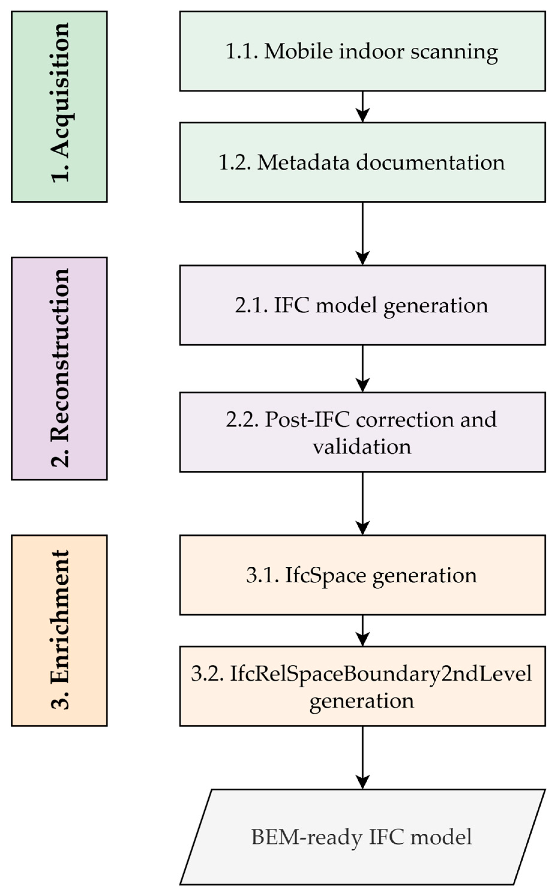
The overall workflow can be viewed in Figure 1 and consists of three main parts. The first part concerns semantic indoor data acquisition, in which room-scale building components are detected and exported in a structured data format. The second part concerns IFC reconstruction, in which the detected elements are converted into an IFC 4×3 ADD2 model with a strict spatial hierarchy, nested local placements, swept-solid geometry, wall-opening-window relationships, and BEM-oriented analytical closure. The intended output of this part is not a fully detailed architectural as-built model, but a geometrically closed and semantically consistent IFC model that can be further processed for energy analysis. The third part concerns model enrichment, in which the reconstructed IFC model is extended with the IfcSpace entities and second-level IfcRelSpaceBoundary relationships required for BEM generation. This stage operates on the validated geometric output of the reconstruction phase and performs two complementary tasks: it identifies and instantiates thermal zones as bounded volumetric spaces, and it classifies each bounding surface according to its physical role and adjacency conditions. A key requirement throughout the entire workflow is that the generated IFC model must support the downstream interpretation of spaces, boundaries and openings. The reconstruction process therefore focuses exclusively on elements relevant for energy modelling, such as room volumes, floors, walls, windows, openings, inferred ceilings, and spatial containment relationships, while furniture and movable objects are excluded, as they do not contribute to the generation of thermal space boundaries.

3.1. Acquisition

The first stage of the pipeline concerns the capture and structuring of room-scale building data. It is subdivided into two subphases, namely mobile indoor scanning and metadata documentation.

3.1.1. Mobile Indoor Scanning

Apple RoomPlan was used as the prototype implementation of the semantic recognition stage. RoomPlan enables LiDAR-supported mobile indoor scanning and returns structured room-scale data describing architectural elements such as walls, floors, windows, doors, openings, and detected objects. In this study, RoomPlan is treated as an implementation choice rather than as a methodological limitation of the proposed pipeline. The essential requirement of the workflow is not the use of RoomPlan itself, but the availability of semantically classified indoor building elements with geometric transforms, dimensions, identifiers, and host relationships.
It is important to clarify that the proposed prototype does not use raw point clouds as direct input. Although Apple RoomPlan relies on LiDAR and ARKit sensing during capture, the data processed by the proposed workflow are the semantically structured RoomPlan JSON files exported after scanning. These JSON files contain recognized architectural elements, such as walls, floors, openings, doors, and windows, together with dimensions, transforms, identifiers, and host relationships. Therefore, the pipeline operates on semantic scan output rather than on point-cloud segmentation results.
A custom iOS application was implemented using SwiftUI, RoomCaptureView, and RoomCaptureSession. The application supports continuous scan-segment acquisition instead of requiring one scan per individual room. Each scan segment may contain a corridor portion, adjacent rooms, visible doors or windows, openings, or another partial indoor zone. This acquisition strategy was selected to keep the workflow lightweight while reducing the drift and scene-size limitations that can occur when attempting to capture a complete building or a long corridor in a single scan. Instead of relying on a complete floor scan, the building area is captured as a set of manageable scan segments that can later be processed and combined in the IFC workflow.
For each completed scan segment, the processed CapturedRoom object is exported as a RoomPlan JSON file. The exported file contains lists of detected elements, including walls, floors, windows, doors or openings, and objects. Each element contains a unique identifier, category information, dimensions, confidence information and a 4 × 4 transformation matrix. Where available, floor elements also contain polygon corner coordinates. Wall-hosted elements, such as windows and doors, may include a parentIdentifier, which links the hosted element to its detected parent wall. This host relationship is used later to reconstruct IFC opening, window and door relationships.
Because RoomPlan can detect furniture and movable objects, the raw JSON may contain elements such as tables, chairs, cabinets, shelves, or storage objects. These elements are not exported as IFC building elements in the current workflow. The conversion focuses on architectural and BEM-relevant elements. This filtering avoids introducing movable or non-thermal objects into the BEM-oriented IFC model.

3.1.2. Metadata Documentation

In addition to the individual RoomPlan JSON files, the scanner exports a session-level scan_manifest.json. The manifest records information that cannot be reliably inferred from RoomPlan alone, including the building name, scan session identifier, start and end floor, scan type, storey number, sequence index, contained room labels, corridor identifiers, scan context information, vertical connection metadata, and notes. Scan types include CORRIDOR_WITH_ROOMS, CORRIDOR_ONLY, ROOM_ONLY, STAIR_REFERENCE and OTHER. These labels describe the role of each scan segment in the later IFC reconstruction. For example, a CORRIDOR_WITH_ROOMS scan may contain a corridor portion and several adjacent rooms, but it is not automatically split into separate room spaces in the current prototype.
The manifest also records contextual relationships between scan segments and floors. Same-storey scan segments can be described through sequence and scan-context metadata, while scan segments on different storeys can be linked through vertical connection metadata. Since RoomPlan does not reliably reconstruct stair geometry, stair connections are represented as metadata rather than as measured stair geometry. For example, scan segments on two different storeys can share the same verticalConnectionId, such as “STAIR_A”, to indicate that they are connected through the same stair access or vertical circulation point. This information is later transferred to the IFC model as vertical connection metadata.
Because mobile scanning in existing buildings is often constrained by accessibility and tracking stability, the scanning workflow also supports partial building capture. In the case study, only accessible parts of the west wing were scanned, while non-public office rooms were excluded. The manifest therefore defines the survey extent explicitly, so that the generated model represents the scanned and reconstructed area rather than the entire building wing. This is important for later analytical closure, because open boundaries in a partial scan must be treated as reconstruction assumptions rather than as measured building boundaries.

3.2. Reconstruction

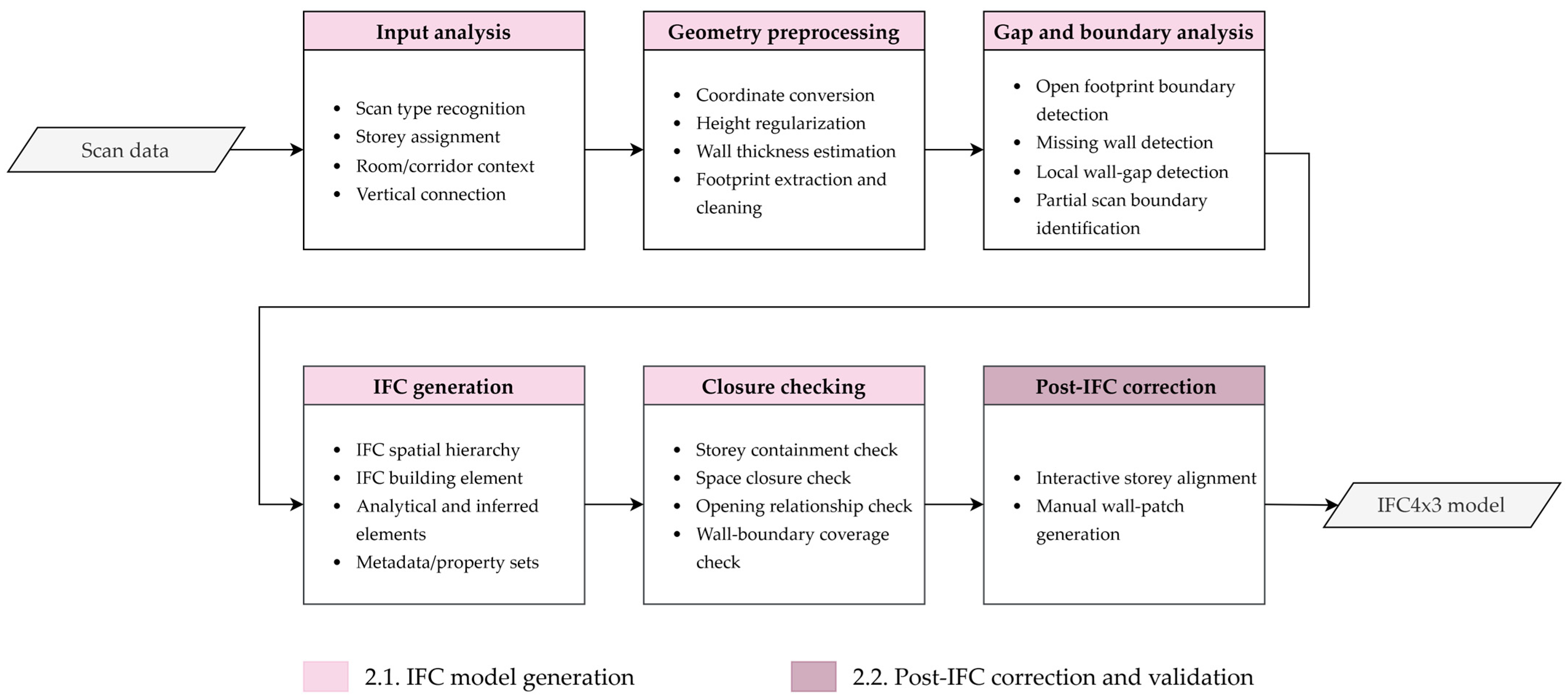
The overall workflow of the RoomPlan-to-IFC 4×3 ADD2 exporter is shown in Figure 2. The process starts with RoomPlan scan data and session-level metadata, followed by input analysis, geometry preprocessing, gap and boundary analysis, IFC generation, closure checking, and optional post-IFC correction. The workflow is organized into two main stages in the following subsections: initial IFC model generation and post-IFC correction and validation.

3.2.1. IFC Model Generation

The RoomPlan scan data are converted into an IFC 4×3 ADD2 model using a Python-based exporter implemented with IfcOpenShell (version 0.8.4) [47] and NumPy (version 2.2.6) [48]. The exporter supports two input modes: a single RoomPlan JSON file or a scan session folder containing multiple RoomPlan JSON files and a scan_manifest.json. In folder-based processing, the manifest acts as the main input controller. It specifies which JSON files are loaded, assigns scan segments to storeys, provides scan identifiers, defines scan types, records room and corridor context, and stores vertical connection metadata. The manifest “storey” field is used as the source of truth for assigning scan data to IfcBuildingStorey entities.
Before geometry generation, RoomPlan coordinates are converted to the IFC coordinate system. RoomPlan and ARKit use a Y-up coordinate system, while IFC uses a Z-up coordinate system. The implemented conversion maps Apple X to IFC X, Apple Z to IFC Y, and Apple Y to IFC Z. This coordinate conversion is applied consistently to walls, floors, windows, doors, openings, inferred ceilings, post-processing geometry and debug outputs.
The exported model follows the standard IFC spatial hierarchy. For each output model, one IfcProject, one IfcSite and one IfcBuilding are created, while one IfcBuildingStorey is generated for each storey value defined in the scan manifest. Each storey is assigned an elevation and a local placement relative to the building placement. All scan-derived and inferred elements are then placed and spatially contained within their corresponding storey, ensuring a consistent IFC structure for downstream processing. Storey elevations can be calculated using a session-relative rule based on the manifest start floor and a predefined storey height, or by stacking storeys according to normalized scan height. This avoids independent absolute placements and ensures that vertical separation between storeys is represented consistently in the IFC geometry.
All principal geometric elements are represented using swept-solid geometry. RoomPlan walls are converted into IfcWall entities. Wall length is derived from the RoomPlan dimensions, while wall height is regularized for BEM use. Wall thickness is assigned using a hierarchical strategy: a valid RoomPlan thickness is used when available, otherwise adjacent wall surfaces may be used to estimate thickness, and a default value is used when neither source is available. Each wall is generated as an IfcExtrudedAreaSolid based on a rectangular profile. Scanned walls are marked as measured RoomPlan-derived elements through reconstruction-status metadata.
RoomPlan floors are converted into IfcSlab entities. When polygon corner data are available, the local floor polygon points are transformed, converted to IFC coordinates, projected onto the IFC XY plane, cleaned where necessary, and used to create an IfcArbitraryClosedProfileDef. If only dimensions are available, a rectangular fallback profile is used. To avoid floating floors caused by scanning noise, floor slabs are regularized to local Z = 0 relative to the storey. When same-storey footprint merging is enabled, individual segment floor slabs can be suppressed and replaced by a merged floor slab derived from the union of scan footprints.
The exporter includes a same-storey overlap cleaning and footprint merging step. For each scan segment, the main floor polygon is extracted, closed, cleaned and simplified where safe. For each storey or merge group, valid floor polygons are combined using two-dimensional polygon union. Small gaps can be closed within a defined tolerance. The resulting merged footprint is used as the geometric basis for floor slab generation, inferred ceiling generation, and later analytical space reconstruction. By default, overlapping segment-level slabs can be suppressed when a merged storey footprint is available. This prevents scan overlap from producing duplicate floor geometry and provides a cleaner footprint for the subsequent BIM-to-BEM workflow.
Because RoomPlan does not provide ceiling geometry, the converter generates inferred ceiling slabs for analytical closure. For each merged or segment-based footprint, an inferred ceiling slab is created at the normalized wall height. The inferred ceiling is explicitly marked as generated rather than scanned. This distinction is important because the method does not claim that the original scan captured complete ceiling geometry; instead, it creates a transparent analytical closure suitable for downstream energy modelling.
Wall heights are regularized for BEM-oriented consistency. Valid wall heights are collected per storey or per scan group, and a normalized height is calculated, typically using the median of valid detected wall heights. Floor slabs are constrained to the storey base, wall bottoms are set to local Z = 0, wall tops are adjusted to the normalized height, analytical spaces are extruded to the same height, and inferred ceilings are placed at the normalized wall top. Original scanned heights and adjusted values are preserved as metadata. This regularization corrects minor scan-induced height variations and supports the generation of geometrically closed analytical volumes.
Because the regularized height is derived from RoomPlan-detected wall heights, the resulting analytical space volume may inherit systematic height bias if the mobile scan underestimates the true room or storey height. For this reason, the normalized height should be reviewed and, where reliable building information is available, calibrated against known room heights, storey heights, or physical measurements before quantitative energy simulation.
Windows and doors are reconstructed as wall-hosted elements rather than as independent objects. For each RoomPlan window or door, the converter identifies the corresponding parent wall using the parentIdentifier. The wall-hosted relationship is represented in IFC by creating an IfcOpeningElement for the void in the parent wall. This opening is related to the wall through IfcRelVoidsElement, while the corresponding IfcWindow or IfcDoor is assigned to the opening through IfcRelFillsElement. In this way, windows and doors are represented according to the standard IFC void-and-fill mechanism instead of being exported as independent and unhosted objects.
The placement of hosted elements is computed in the local coordinate system of the parent wall. The exporter transforms the RoomPlan hosted element geometry using the same coordinate conversion chain as the rest of the scan, then evaluates candidate wall-local bounding boxes from the RoomPlan element transform and dimensions. From these wall-local bounds, the converter derives the opening centre, width, height, and vertical position. This avoids using a fixed vertical offset and ensures that window and door positions remain tied to their parent walls after storey placement and footprint processing. Small wall-bound violations can be clamped, and the selected placement method, bounds, reference interpretation, and any correction are stored in metadata. Wall height regularization does not overwrite window height or sill position.
Partial scans of corridors or building zones may contain open boundaries. To provide a closed analytical model for BEM, the exporter can generate inferred closure walls along open edges of the merged or active footprint where no scanned wall is detected. Each boundary edge is compared against nearby scanned walls on the same storey. If an edge is not covered by a scanned wall and exceeds a minimum length, an inferred IfcWall is generated. These walls are named and marked differently from scanned walls, for example as inferred boundary walls. Their reconstruction-status metadata records that they were generated from open footprint boundaries for BEM analytical volume closure.
In addition to large open boundaries, the exporter can address local incompleteness caused by unstable tracking, occlusion, or partial wall detection. If the active footprint indicates a room or corridor boundary that is not sufficiently covered by scanned wall elements, a missing wall segment can be generated as an inferred wall. Small gaps between neighbouring wall endpoints can also be patched using short, inferred wall-gap elements. These operations are intended to support analytical space closure and are not treated as measured geometry. Therefore, the generated elements are explicitly marked as inferred or manually defined reconstruction elements.
The exporter also transfers scan-level and reconstruction metadata into the IFC model through property sets. These property sets record RoomPlan source information, scan segment metadata, scan session metadata, reconstruction status, geometry regularization, hosted element placement, wall thickness estimation, merged footprint assumptions, BEM boundary assumptions, inferred boundary walls, space adjacency, and vertical connection metadata. This metadata is used to distinguish scanned elements from inferred elements and to make BEM-related assumptions explicit.

3.2.2. Post-IFC Correction and Validation

After the initial IFC model has been generated, the workflow supports optional interactive post-processing tools. These tools operate on the generated IFC file rather than on the original RoomPlan JSON data. A post-IFC storey alignment tool can be used to adjust the relative horizontal position of already reconstructed storeys as rigid objects. This approach preserves the internal closure of each storey while improving inter-storey correspondence. In addition, a manual wall-patch interface can be used when a missing wall segment remains visible after automatic correction. The user selects a direction wall and a target wall in a top-view interface, and the tool generates an inferred patch wall that connects the selected walls. The new patch wall is added as an independent IfcWall, assigned to the same IfcBuildingStorey as the reference wall, and marked as a user-defined inferred element. These post-processing tools support practical correction without requiring the original scan-to-IFC conversion to be rerun.
After IFC generation and optional post-processing, the model is validated and debug outputs are produced. The validation checks the spatial hierarchy, storey creation and placement, nested IfcLocalPlacement, element containment, swept-solid geometry, absence of exported furniture, hosted opening relationships, window and door placement relative to openings, opening placement relative to parent walls, wall-local bounds of hosted elements, merged space closure, inferred ceiling placement, inferred closure wall status, adjacency metadata, vertical connection metadata, and the presence of required storey containment relationships. Debug outputs can include scan overview plots, wall-pair reports, height regularization reports, same-storey merge plots, inferred boundary wall plots, vertical placement reports, hosted element placement reports, storey alignment reports, and manual wall-patch reports. The resulting IFC 4×3 ADD2 model is then passed to the subsequent BIM-to-BEM workflow, where the energy-related interpretation of spaces, surfaces, openings, and boundary assumptions is performed.

3.3. Enrichment

The validated IFC model serves as input for the space and space boundary generation stage, implemented in Python 3.10 within a Miniconda3 (version 26.1.1, Anaconda, Inc., Austin, TX, USA) environment [49] to ensure compatibility with pythonOCC (pythonocc-core, version 7.9.3) [50], the Python binding of the OpenCASCADE geometry kernel (OCCT, version 7.9.3, Open Cascade SAS, Guyancourt, France) [51]. The stage is organized into two sequential parts. The first concerns the generation of IfcSpace entities, which define the volumetric extents of individual rooms by reconstructing enclosed spatial units from the interior-facing surfaces of the building envelope. The second concerns the derivation of IfcRelSpaceBoundary relationships, which associate each space with the building elements that physically delimit it and classify each boundary surface according to its thermal role and adjacency conditions. Both parts operate on the same geometric foundation and share a common set of B-rep processing utilities, combining IfcOpenShell for IFC read and write operations with OpenCASCADE primitives for all geometric reasoning.

3.3.1. IfcSpace Generation

The proposed pipeline is conceptually related to the ASG algorithm introduced by [39], which reconstructs building space volumes from the geometric representations of surrounding architectural elements and enriches the IFC model accordingly. The present work extends this approach in two main respects. First, whereas ASG assumes a geometrically correct input model and treats imperfections as failure conditions, the proposed pipeline is designed to operate on scan-derived IFC models in which geometric inconsistencies are structurally inherent, addressing them through the upstream validation and cleaning stage. Second, while ASG performs polygon operations in two-dimensional projected space via the Clipper library, the present pipeline operates directly in three-dimensional B-rep space using the OpenCASCADE kernel, which is better suited to the non-axis-aligned geometries typical of scan-derived input. A known limitation of the current prototype with respect to ASG is the absence of an explicit mechanism for handling clash-induced internal surfaces, which in ASG are collected into a dedicated set to prevent the incorrect merging of adjacent spaces; this remains a direction for future refinement.
The IfcSpace generation pipeline is structured across six sequential sub-stages, each addressing a distinct aspect of the transformation from validated building geometry to semantically enriched spatial entities, listed below:
  • Geometry extraction;
  • Volumetric conflict resolution;
  • Face matching;
  • Free surface identification;
  • Topological grouping;
  • IfcSpace instantiation.
In the geometry extraction sub-stage, building elements, such as walls, slabs, roofs, columns and windows, are retrieved from the IFC model and their boundary faces collected. Each face is enriched with semantic metadata, including the originating IfcElement reference, surface normal, centroid, and bounding box to support subsequent geometric reasoning. Elements with tessellated representations undergo a preliminary cleaning procedure before face extraction, addressing the geometric inconsistencies typical of scan-derived input.
The second sub-stage addresses the geometric inconsistencies inherent to scan-derived IFC models. The latter are often characterized by volumetric overlaps between adjacent building elements, which could corrupt the subsequent face extraction by introducing spurious internal surfaces at element boundaries, thereby preventing the correct identification of the space-enclosing geometry. The cleaning procedure operates on the full set of solid geometries extracted in the preceding sub-stage. For each pair of solids whose bounding boxes overlap, a Boolean intersection is computed. A non-negligible intersection volume indicates a volumetric overlap between the two elements. In such cases, the shared volume is removed from one of the two solids via a Boolean cut operation. The choice of target solid is governed by a priority hierarchy that establishes which volume must be preserved: elements of type IfcSlab and IfcRoof hold higher priority than IfcWall elements and are therefore preserved in the event of a conflict. Where both elements belong to the same priority class, the first element in the iteration order is selected as the cut target. The result is a dictionary of cleaned solids, in which each building element is represented by a non-overlapping B-rep solid, ready for face extraction in the subsequent sub-stage.
The third sub-stage identifies pairs of faces that bound a shared construction thickness through a chain of sequential geometric predicates: bounding box overlap, normal anti-parallelism, coplanarity, and confirmed geometric intersection. The chain is evaluated in order of increasing computational cost, so that expensive intersection tests are only performed when all cheaper conditions are already satisfied. Only face pairs satisfying all conditions are retained as matched pairs.
From each matched pair, the fourth sub-stage isolates the free portion of each face, that is, the surface area not covered by the opposing face, through a Boolean subtraction operation. This operation yields two distinct categories of free surface: the interior-facing surfaces of the building elements, which delimit the room volume from the inside, and the exterior-facing surfaces, which bound the building envelope towards the outside. Both categories are retained at this stage, as the subsequent topological grouping relies on the full set of free surfaces to reconstruct closed spatial units.
The topological grouping sub-stage partitions the free surfaces into candidate room volumes through graph-based connectivity analysis. Faces sharing a common edge are connected through an adjacency relation, and a depth-first search traversal partitions the full-face set into connected components, each representing a candidate enclosed space. Each component is assembled into a closed shell and promoted to a solid. Shell orientation is then verified through the sign of the computed volume, a criterion grounded in the divergence theorem: for a closed orientable surface, the sign of the volume integral depends on whether the face normals point consistently outward or inward. This property, formalized in the ISO 10303-42 standard [52] for manifold solid B-rep representations and inherited by the IFC schema through IfcManifoldSolidBrep, is exploited directly by the OpenCASCADE kernel, where a negative computed volume indicates an inward-oriented shell corresponding to an enclosed interior space. Only solids satisfying this condition are retained for further processing. The IfcBuildingStorey associated with each group is inferred by majority vote over the storeys of the constituent building elements.
In the sixth and final sub-stage, each detected volume is instantiated as an IfcSpace entity within the IFC schema. The geometric characterization of each space follows the implicit representation convention of the IFC format, in which the room volume is encoded as an IfcFacetedBrep composed of a set of planar faces assembled into an IfcClosedShell. Since IFC geometry is expressed in the local coordinate system of the parent IfcBuildingStorey, the vertex coordinates of the previously extracted boundary surfaces are transformed from the global coordinate system into the storey-relative local frame before entity instantiation. Each space is then linked to the spatial hierarchy through IfcLocalPlacement and associated with its geometric representation via IfcProductDefinitionShape.
The enriched model is finally serialized to a new IFC file, providing the spatial structure required for the subsequent space boundary generation stage.

3.3.2. IfcRelSpaceBoundary2ndLevel Generation

The second part of the enrichment stage concerns the generation of IfcRelSpaceBoundary entities at the second level of detail, as defined by [38]. A second-level space boundary encodes the geometric and semantic relationship between a bounding surface of an IfcSpace and the building element that physically provides that boundary.
The generation of second-level space boundaries presupposes the availability of both IfcSpace entities and IfcBuiltElement instances in the input model, as the boundary relationship maps the intersection between the volumetric extent of a space and the physical surfaces of the surrounding construction elements.
Therefore, the generation of second-level space boundaries represents one of the most critical stages in BIM-to-BEM processes, as the resulting surfaces constitute the direct geometric input for the building energy model. The algorithm developed in the present work follows the existing literature on the automatic generation of space boundaries from IFC files, with reference to the Common Boundary Intersection Projection (CBIP) algorithm proposed by [41], over which it introduces methodological extensions. In its original formulation, CBIP is anchored to the Design Transfer View 1.0 [53], a Model View Definition (MVD) referencing the IFC 4 ADD1 schema, now superseded, which does not contemplate the classes and relationships introduced in subsequent versions of the standard. The algorithm proposed in the present work is instead developed in conformance with updated IFC schema versions, namely IFC 4 ADD2 TC1 and IFC 4×3 ADD2, ensuring compatibility with files produced by currently available BIM authoring tools.
Similarly to the CBIP method, the proposed algorithm operates on the polyhedral geometric representations of IFC entities, classifying elements into constructions (IfcWall, IfcSlab, IfcRoof, IfcColumn), openings (IfcOpeningElement), and spatial volumes (IfcSpace). The presence and geometric correctness of IfcSpace entities in the IFC file constitutes a prerequisite shared with CBIP. In the context of the present work, focused on a mobile-indoor-room-scan-to-BIM-to-BEM approach, this requirement is structurally satisfied by the space generation algorithm described in the previous section, which produces geometrically valid solids as direct output of the point cloud segmentation and reconstruction process. No additional verification or correction phase is therefore required before the execution of the space boundary generation algorithm.
In terms of computational performance, the proposed algorithm introduces a three-dimensional spatial indexing structure based on an R-tree, built from the bounding boxes of the construction elements. For each IfcSpace, the candidates to be analysed are selected via index query, limiting the number of Boolean operations to those elements geometrically proximate to the space under examination. This optimization, not described in [41], is intended to improve the scalability of the algorithm for large-scale building models. As an indication of computational performance, the space boundary generation algorithm was additionally tested on a larger IFC model of a different building, comprising 367 IfcSpace instances, for which the generation of second-level space boundaries required approximately 1.47 s per space on average. A quantitative evaluation of the specific contribution of the R-tree indexing to this performance, including comparison against a non-indexed implementation, falls outside the scope of the present work.
The space boundary extraction phase is based on an iterative fragment-based approach: each face of the space solid is progressively subdivided through successive Boolean intersection operations with the candidate construction elements, extracting the contact portion as a physical space boundary, and subtraction operations, which return the residual portion to be compared with the subsequent elements. Portions that do not intersect any construction element are processed in a subsequent stage.
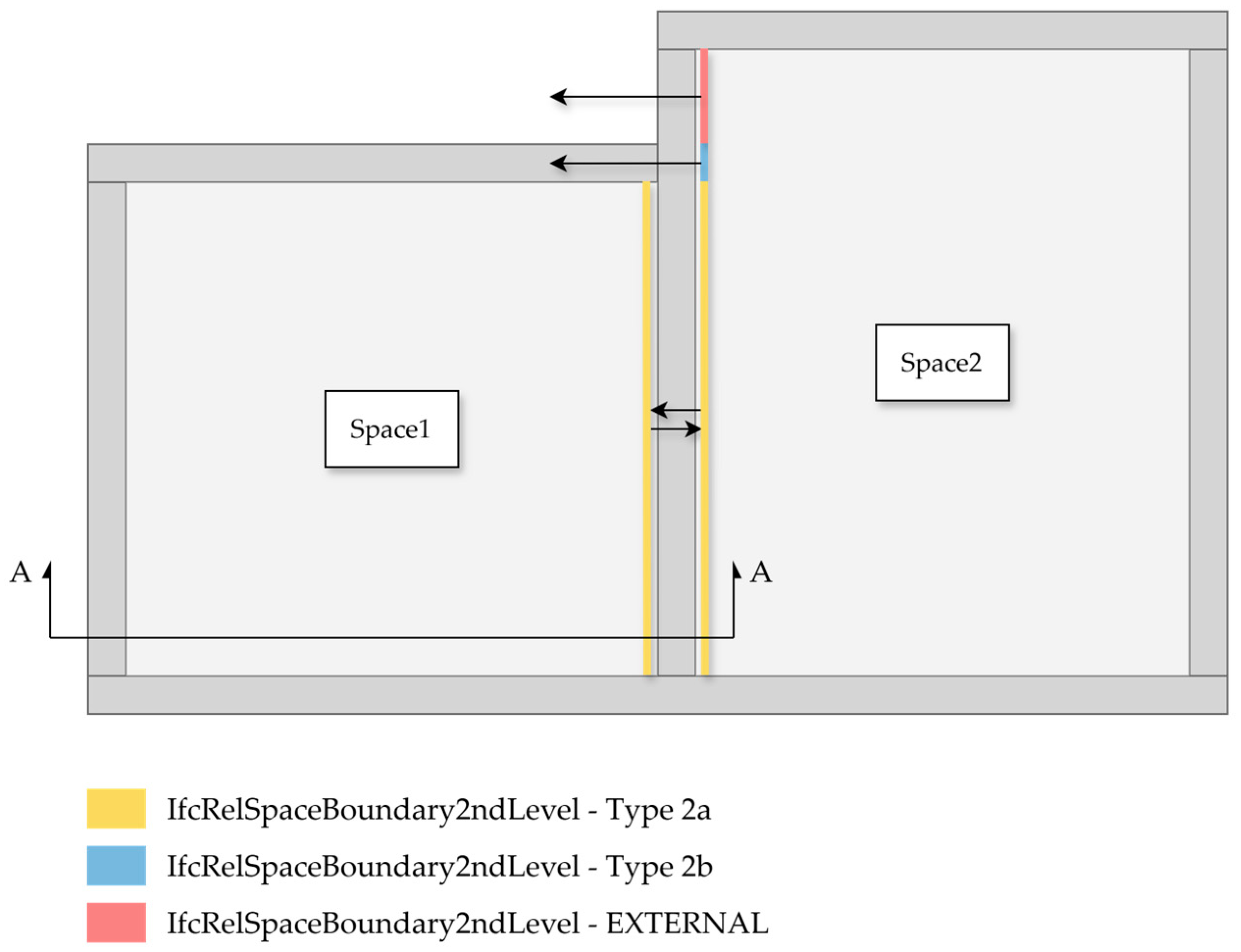
The approach described above enables the identification of space boundaries at an intermediate level between the first and the second level: these boundaries account for the variation in the construction element, while disregarding the surrounding context. To proceed with the identification of second-level space boundaries, an additional geometric decomposition is therefore introduced. This decomposition is carried out through reciprocal projection and intersection of the contact surfaces identified for pairs of adjacent spaces sharing the same construction element, by analogy with the Boundary Intersection Projection (BIP) process described in [41] and with the projection and clipping approach adopted by [19]. The projection is always performed from the face with the smaller area onto the face with the larger area, ensuring that the resulting common portion is geometrically contained within the larger face. The common portion represents a space boundary delimiting two distinct IfcSpace entities, classified as type 2a according to the IFC data model. As a result, the identification of type 2a surfaces presupposes the availability of a corresponding surface associated with an adjacent IfcSpace. Where such an IfcSpace, and consequently such a surface, is not available, the residual surface is instead carried forward to the subsequent ray tracing-based classification stage, where it is evaluated against the candidate construction elements, as detailed below.
For the remaining surfaces, such as the residual portions of the space face from the type 2a classification process or those not covered by any construction element, the algorithm implements a ray tracing-based classification. For each surface, the centroid and outward normal are computed, verifying that the latter points towards the exterior of the space. A ray is emitted from the centroid in the direction of the normal, and its intersection with the faces of the candidate construction elements is evaluated within a maximum distance threshold. The classification follows a decreasing priority logic: firstly, if the ray does not intersect any face of the element, the element has not yet been fully traversed. Secondly, if after traversing the current element the ray intersects a further construction element, or if the exit point is contained within the solid of another element or within the same space of origin, the surface is again classified as type 2b, corresponding to an internal adiabatic surface located at a material variation or geometric discontinuity. In the absence of such conditions, the surface is classified as external (Figure 3).
It should be noted that, in the case of partial scans, surfaces located at the perimeter of the surveyed area lack an adjacent IfcSpace, a requirement for their classification as type 2a boundaries. Such surfaces are therefore evaluated in the subsequent ray tracing-based classification stage and, not intersecting any construction element, are classified as EXTERNAL, regardless of whether the opposite side corresponds to the outdoor environment or to an unscanned interior space.
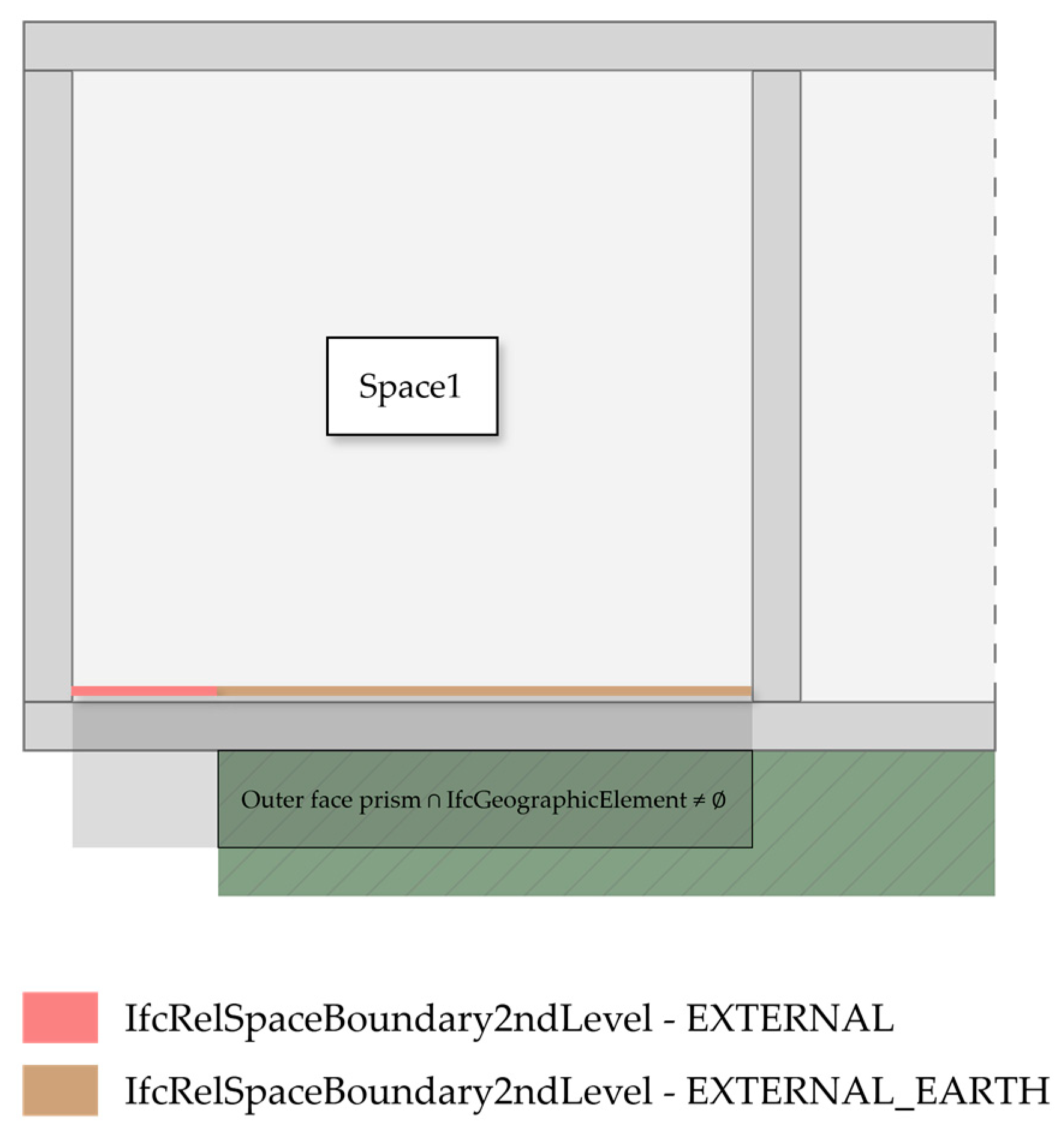
Surfaces classified as external are subjected to a further distinction between EXTERNAL and EXTERNAL_EARTH using a dedicated function. Starting from the residual face, a prism is constructed by extrusion in the direction of the outward normal; the intersection of this prism with the solid of the construction element returns the portion of the element extending beyond the boundary surface. The outer face of this portion is then intersected with the solids of the IfcGeographicElement entities present in the model: coincident portions are classified as EXTERNAL_EARTH, while the remaining portions are classified as EXTERNAL. In both cases, the resulting geometries are reprojected onto the original inner face before being included in the output (Figure 4).
This distinction, not addressed in [41], is relevant for energy simulation purposes, as surfaces in contact with the ground are subject to different thermal boundary conditions compared to those exposed to outdoor air.
To guarantee the volumetric closure of the set of space boundaries pertaining to each IfcSpace, a third output category is introduced, referred to as unresolved boundaries. It collects the portions of the space face that, at the end of the classification process, have not been matched to either physical construction elements or adjacent spaces. Although representing an anomalous condition, indicative of residual geometric inaccuracies in the model or architectural configurations not handled by the preceding stages, their inclusion is necessary to prevent the volume delimited by the space boundaries from remaining open, a condition that would compromise the correctness of the energy simulation. The resulting IfcRelSpaceBoundary relationship is characterized by a Description attribute set to “UnresolvedBoundary” and by the PhysicalOrVirtualBoundary attribute set to NOTDEFINED, explicitly signalling its indeterminate nature.
Their correct classification can be performed manually within the target BEM software, where appropriate thermal properties can be assigned before the execution of the simulation. Although recourse to this category should be considered exceptional and symptomatic of upstream modelling issues, it ensures in any case the complete closure of the spatial volume and the consequent executability of the simulation, while simultaneously serving as a diagnostic tool for the manual verification of the model.
In the space boundary creating phase, the geometry of each surface is encoded according to the schema defined by the IFC data model, expressing each boundary in the local coordinate system of the corresponding IfcSpace. For IfcOpeningElement entities, the local coordinate system is inherited from the parent opaque element, ensuring geometric coplanarity between the space boundary of the opening and that of the hosting element, in conformity with the requirements of the IFC standard and with the indications of [19].

3.4. Case Study

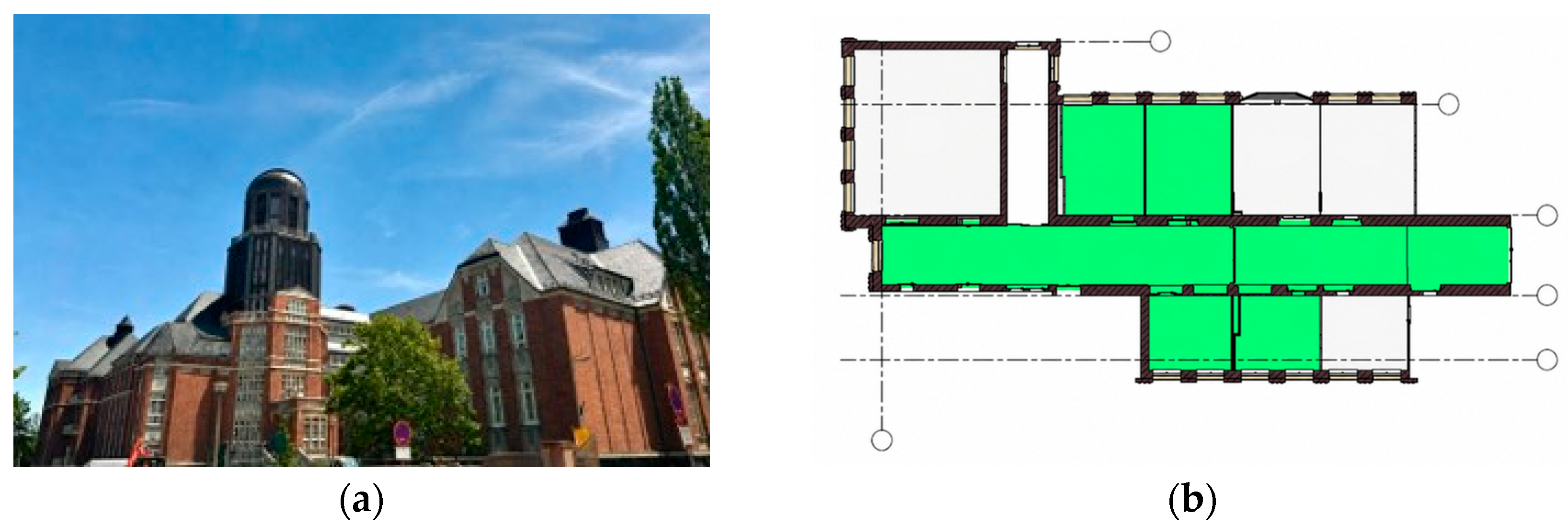
The effectiveness of the overall methodology is validated on a real case study, represented by the BeyerBau building, part of the campus of the Technische Universität (TU) Dresden, located at George-Bähr-Straße 1, Dresden (DE). Designed by Martin Dülfer, the university building was constructed between 1910 and 1913. From an architectural standpoint, it spans nine levels, two of which are below grade and seven above, and is particularly notable for the 41-metre Lohrmann Observatory tower. Between 2018 and 2025, the building underwent a comprehensive renovation aimed at preserving its historic character while simultaneously adapting it to the modern demands of university teaching and research (Figure 5a).
The model generated in the present work constitutes a prototype derived from mobile scanning survey data and is applied to a selected portion of the building, specifically part of the west wing on the first and second floors. Due to the functional use of the building, most rooms in the west wing are office rooms and are therefore not publicly accessible. For this reason, the case study was limited to an accessible subset of the west wing, covering four rooms: 111, 112, 118, and 119, together with the associated corridor segments. A floor plan of the selected area is provided in Figure 5b to illustrate the spatial extent of the scanning campaign and the relationship between the scanned rooms and the surrounding corridor zone.
The generated model conforms to the IFC 4×3 ADD2 schema. Although the prototype represents only a partial section of the building, it is derived from a real and architecturally complex existing building. The BeyerBau case study is therefore suitable for evaluating the proposed methodology under realistic geometric, spatial, and semantic conditions. The complexity of the building, including its historic construction, multi-storey configuration, corridor–room organization, and partial accessibility constraints, provides a meaningful test environment. If the proposed workflow can generate a usable analytical IFC model from such a constrained and irregular case, it suggests that the methodology is also applicable to more common urban buildings with less complex spatial conditions.
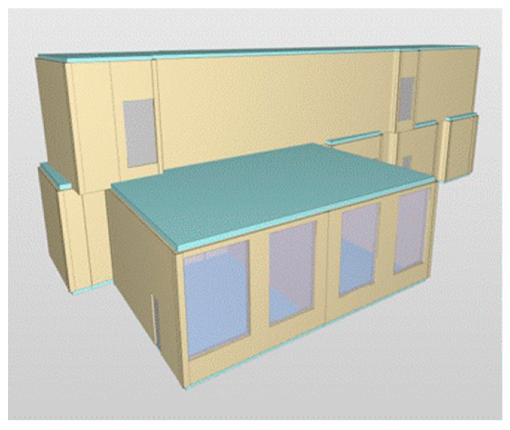
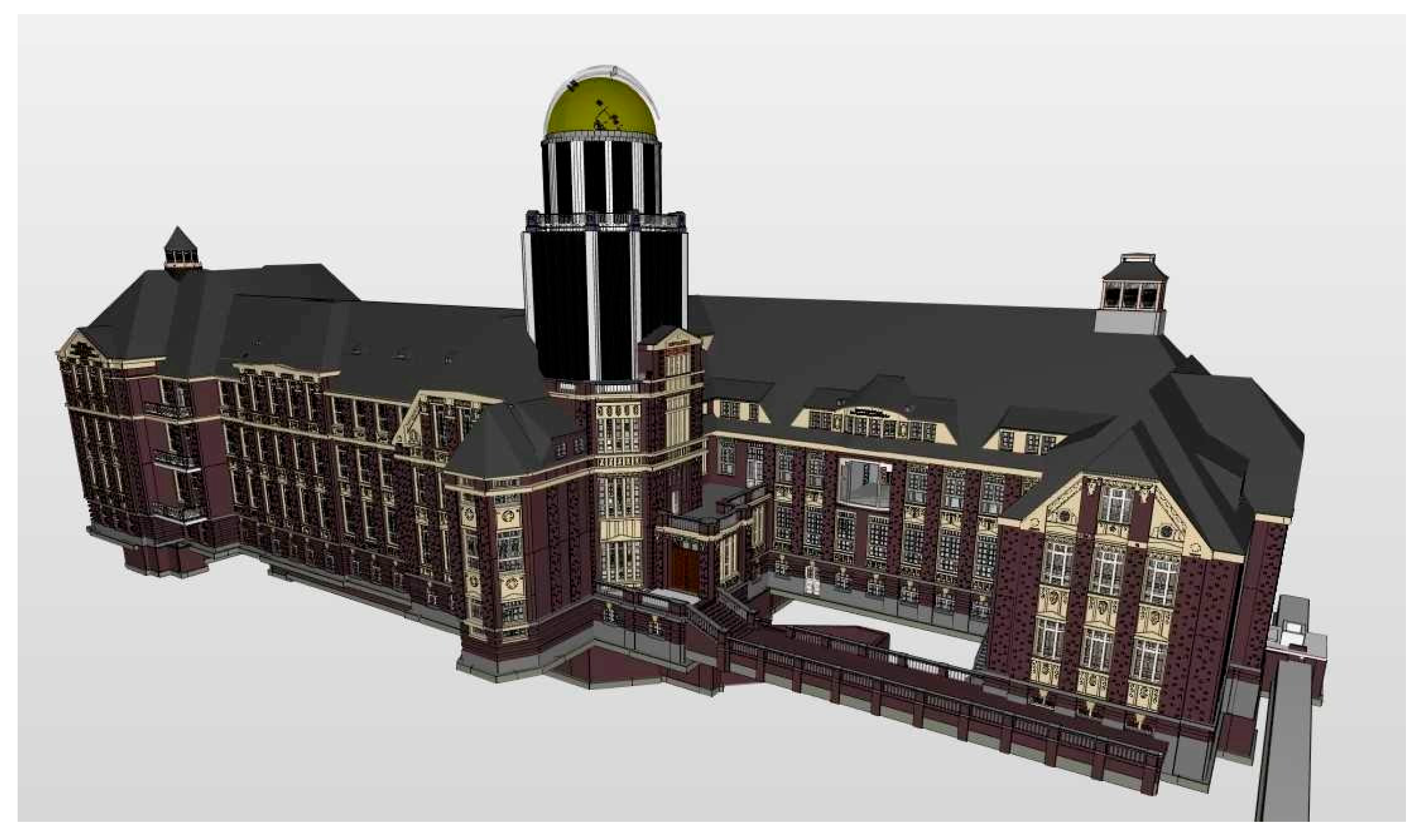
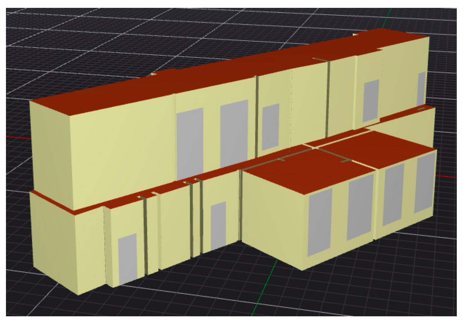
In addition to the scan-derived IFC model, a conventionally modelled Revit (version 2024, Autodesk, Inc., San Francisco, CA, USA) model of the BeyerBau building is available and is used as a qualitative reference for validation (Figure 6). The model was created on the basis of CAD floor plans and renovation-related documentation provided by the construction company responsible for the BeyerBau renovation. It therefore represents the most reliable document-based reference available for the case study. The model provides an overall reference for understanding the building geometry and for comparing the selected scan-derived prototype with a conventionally authored BIM. For the scanned west wing area, it supports the evaluation of spatial layout, room arrangement, wall boundaries, and the consistency of generated IfcSpace entities. Since the Revit model was developed and updated over several semesters and covers a broader modelling context than the selected scan-derived prototype, it is not used as a direct quantitative time baseline in this study. Instead, it serves as a document-based comparative reference for the geometric, semantic, and energy-performance evaluation of the selected scan-derived model, rather than as an absolute geometric ground truth or a time-controlled manual-modelling baseline.
The prototype was subsequently enriched through the algorithms described in Section 3.3.1 and Section 3.3.2, which handle the automatic detection and generation of IfcSpace and IfcRelSpaceBoundary entities, respectively.
To validate the correctness of the IFC file, the enriched model was then imported into VICUS Buildings (version 2.0, VICUS Software GmbH, Dresden, Germany) [54], the building energy simulation software developed by the Institut für Bauklimatik at TU Dresden, where the final BEM validation was performed. Its IFC import functionality supports the management of IfcSpace and IfcRelSpaceBoundary entities but does not support the IFC 4×3 ADD2 version. For this reason, a dedicated tool was developed to enable data transfer, based on ifcSQL [55], through which it was possible to generate the .vicus file corresponding to the building under examination. The parsing process, however, falls outside the scope of the present research.
Furthermore, the availability of a conventionally modelled IFC reference model of the same building enables two complementary evaluations: a geometric comparison of the scan-derived IfcSpace entities against their counterparts in the reference model, and an energy-performance comparison under identical construction and usage assumptions. The processing time of the proposed workflow is reported separately, but no direct time comparison with conventional modelling is conducted because a time-controlled manual-modelling baseline was not available.
In addition to the geometric comparison described above, the two IFC models were used to run two energy simulations, in order to assess whether any geometric deviations between the two models translated into significant differences in simulated energy demand. This step extends the validation of the proposed methodology beyond mere schema-level and topological correctness, verifying the actual suitability of a scan-derived energy model to support a performance analysis consistent with that obtainable from a conventionally modelled counterpart. Both energy models were configured identically, to isolate the effect of the input geometry from confounding variability introduced by the simulation settings. This translates into shared general settings, such as the location (Dresden, Germany) and the reference climate file, and into the assignment of identical construction properties. To ensure comparability of boundary conditions, in the conventionally modelled IFC model only the rooms involved in the mobile scanning campaign were isolated, thereby obtaining two energy models referring to the same geometric extent. Consistently in both models, bounding surfaces lacking a corresponding adjacent IfcSpace were treated as external surfaces. The Revit-derived IFC model partially contained information on the stratigraphy of the construction elements, whereas this information was entirely absent in the scan-derived model. Since in neither case was the thermophysical characterization complete, construction properties were defined directly within the simulation environment, adopting the same stratigraphy for both models: where available, the values partially present in the Revit model were retrieved. For elements lacking such information, a single-layer construction was assumed. Table 1 summarizes the resulting construction build-ups and their corresponding thermal transmittance values.
The building was further characterised in terms of operational regime, through the definition of time profiles consistent with the university-related use of the complex: occupancy was assumed on weekdays (Monday–Friday), within the time slot between 7:00 and 18:00.

3.5. AI-Assisted Software Development

Portions of the Python code implementing the pipeline described in this section, including the RoomPlan-to-IFC 4×3 ADD2 exporter and the IfcSpace and IfcRelSpaceBoundary2ndLevel generation algorithms, were drafted with the assistance of Claude Sonnet 4.6 (Anthropic) and ChatGPT-5.5 (OpenAI). All AI-assisted code was subsequently reviewed, tested, and validated by the authors, who take full responsibility for its correctness, functionality, and scientific validity. The design of the pipeline, the definition of the algorithms, and the interpretation of results remain entirely the work of the authors.

4. Results

This section presents the results obtained from the application of the workflow to the aforementioned case study, following the methodological stages described in Section 3.
The proposed scan-to-IFC workflow was applied to the selected west wing area of the BeyerBau building, covering rooms 111, 112, 118, and 119, together with the associated corridor segments. The input data consisted of multiple RoomPlan-based mobile scans exported as semantic JSON files, together with a session-level scan_manifest.json documenting the relationships between scan segments. The mobile scanning process for the selected case-study area required 16 min 32 s, enabling rapid acquisition of the selected building area.
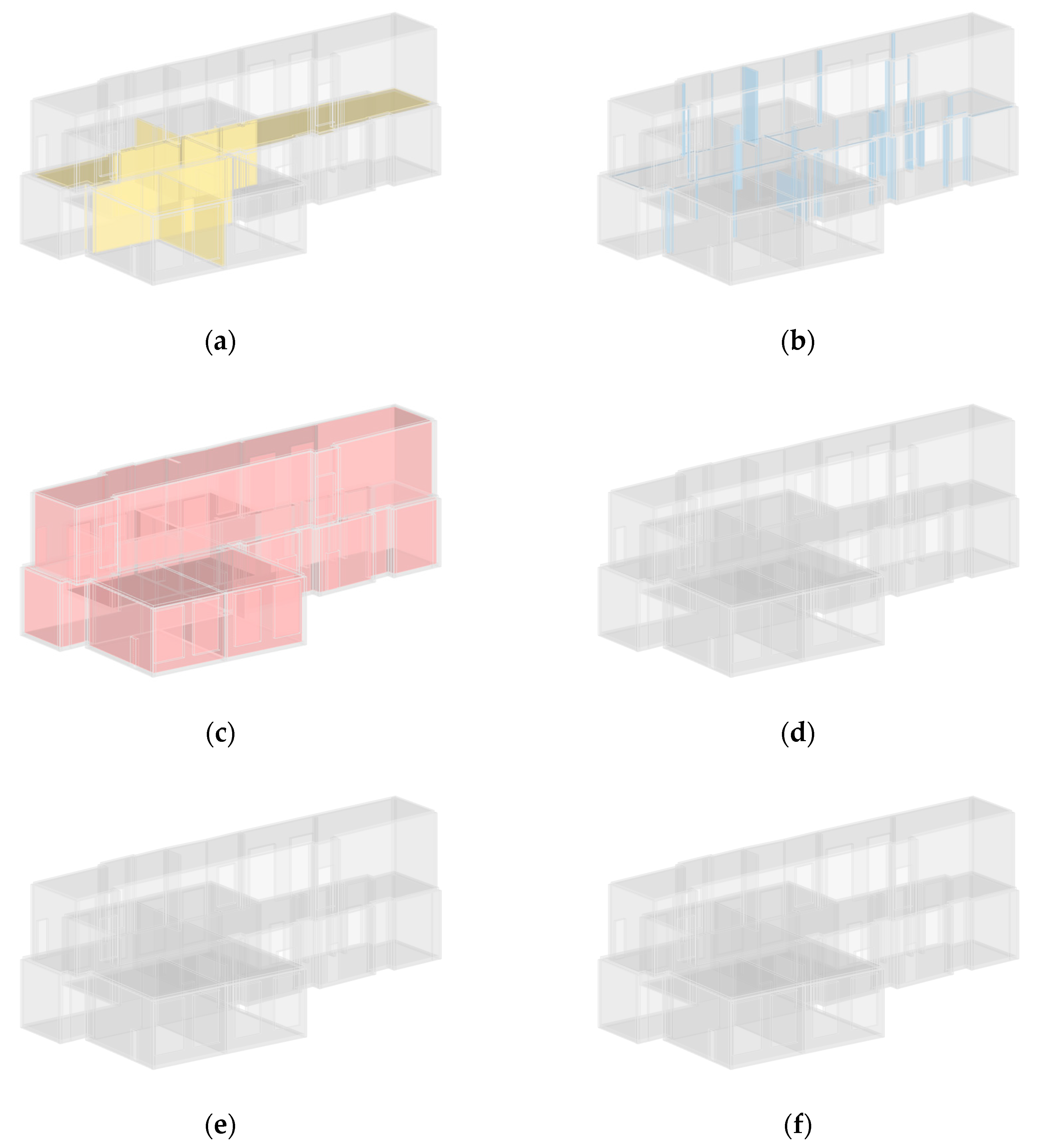
The scans were converted into an IFC 4×3 ADD2 model containing the main building elements required for further BEM preprocessing, including walls, slabs, hosted openings, doors and windows (Figure 7). The exported elements were organized according to the IFC spatial hierarchy, with building elements assigned to their corresponding IfcBuildingStorey. The generated model therefore provides a structured basis for the subsequent creation of IfcSpace and IfcRelSpaceBoundary entities.
The resulting IFC prototype preserved the main spatial configuration of the scanned area, including the corridor–room arrangement and the four selected rooms. During the case study, several limitations of mobile scanning were observed, including small alignment deviations between scan segments and storeys, incomplete wall detection, and local discontinuities between neighbouring wall elements. These limitations affected the direct generation of closed analytical spaces and required additional correction steps.
To address these issues, the generated IFC model was refined using custom-developed post-processing functions. The post-IFC alignment function was used to adjust the relative position of generated storeys while preserving the internal closure of each storey. In addition, closure and patching procedures were applied to compensate for incomplete wall information and local wall gaps.
To make the process effort of the proposed workflow explicit, Table 2 reports the execution time required for the complete pipeline from mobile scanning to VICUS Buildings import for the selected BeyerBau case-study area. The values refer to the corridor segments and four rooms considered in this paper and describe the application of the finalized workflow. In the implemented mobile scanning application, RoomPlan JSON files are exported after completion of the scanning session, together with a session-level scan_manifest.json that documents the relationships between scan segments, storeys, room labels, corridor identifiers, and vertical connections. The Revit reference model was developed and updated over several semesters and is therefore not used as a directly comparable time-controlled manual modelling baseline.
The final scan-derived IFC model contains both directly detected elements and inferred reconstruction elements. Scanned walls, doors, and windows remain identifiable as detected geometry, while closure walls, missing wall segments, and local wall patches are marked as inferred or manually defined elements through dedicated metadata. This allows the generated model to remain traceable and makes it possible to distinguish between scan-derived geometry and geometry introduced to support analytical completeness.
Overall, the result demonstrates that the proposed workflow can rapidly generate a semantically structured and geometrically closed IFC prototype from incomplete mobile scanning data. While the output does not reach the precision or level of detail of the manually authored Revit model, it provides a usable intermediate representation for automatic space generation, boundary detection, and subsequent BEM preprocessing.
The scan-derived IFC model was subsequently submitted to the model enrichment stage, which enabled the generation of IfcSpace and IfcRelSpaceBoundary entities. Through the space detection algorithm, seven IfcSpace entities were identified, as described in Table 3, which reports for each space the name, the assigned building storey, the floor area, and the volume.
From a geometric standpoint, all generated volumes satisfy the topological correctness requirements: all shells are closed and correctly oriented, with no negative or degenerate volumes detected. Furthermore, the volumetric conflict resolution stage was required for all spaces, due to geometric overlaps between adjacent IfcWall and IfcSlab entities. The resolution of these conflicts enabled the elimination of spurious internal surfaces at construction joints, producing an unambiguous envelope geometry for the subsequent face extraction stage. To ensure the semantic correctness of the IFC model, each IfcSpace was correctly assigned to the corresponding IfcBuildingStorey through the IfcRelContainedInSpatialStructure relationship.
The space boundary generation algorithm produced a total of 325 IfcRelSpaceBoundary2ndLevel entities distributed across the seven IfcSpace instances identified in the preceding stage. The boundaries are classified according to their physical role and adjacency conditions, as illustrated in Figure 8 and summarized in Table 4.
EXTERNAL surfaces account for the largest share of the total boundary area (1249.05 m2), corresponding to the envelope elements exposed to the outdoor environment, followed by 2a boundaries (538.96 m2) representing thermally shared surfaces between adjacent spaces and 2b boundaries (98.80 m2). No unresolved boundaries (NOTDEFINED) were produced, confirming the complete volumetric closure of all seven IfcSpace entities.
It should be noted that the set of boundary surfaces classified as EXTERNAL in Table 4 comprises both surfaces that exchange heat with the outdoor environment and surfaces that, in the real architectural configuration of the building, in fact constitute exchange surfaces between adjacent rooms. This aggregation stems from the partial nature of the building scan: the lack of acquisition of the inaccessible portions introduces boundary conditions that do not correspond to the real configuration, since, during the identification of 2a surfaces, no counter-surface from the unscanned adjacent space is available and the residual surface is therefore processed in the subsequent ray tracing classification stage as an external boundary. In the absence of a corresponding boundary on the opposite side of such surfaces, these are consequently treated in the same way as a true external boundary, regardless of their actual thermal nature. For this reason, the reported value of 90 EXTERNAL space boundaries (totalling 1249.05 m2) should not be interpreted as a measure of the building surface exposed to the outdoor environment, but rather as the total area of surfaces lacking a known adjacent space, due to the limited extent of the scan.
Following the generation of the IfcSpace entities and IfcRelSpaceBoundary2ndLevel instances, the enriched IFC model was imported into VICUS Buildings as the final stage of the pipeline. Since VICUS does not natively support the IFC 4×3 ADD2 schema, the import was performed through the ifcSQL parsing module, which converts the IFC data into the VICUS-compatible format.
The successful import confirms the overall correctness of the pipeline. The resulting BEM model faithfully reproduces the hierarchical structure of the source IFC file, encompassing Buildings, Levels, Spaces, Surfaces, and Subsurface. Notably, all space volumes are correctly closed and free of geometric gaps, demonstrating that the space boundary generation algorithm achieved complete volumetric closure for each thermal zone. The VICUS model is shown in Figure 9.
In addition to the qualitative import validation, a comparative energy simulation was performed on the enriched scan-derived IFC model and on the corresponding Revit reference model, following the protocol described in Section 3.4. The comparison was restricted to the heating season (October–April), consistent with the German climatic context, in which winter heating represents the most demanding condition for the building. Both simulations completed without convergence errors, confirming the numerical stability of the scan-derived model within the VICUS solver.
Table 5 reports the coincident peak heating load and the heating demand computed for the seven spaces of the scan-derived model. A quantitative comparison of these results against the Revit reference model is presented and discussed in Section 5.5.

5. Discussion

The results obtained from the application of the proposed workflow to the BeyerBau case study demonstrate its overall feasibility as a scan-to-IFC pipeline oriented towards BEM preprocessing. The following sections interpret the outcomes of each pipeline stage, discuss their implications and limitations, and contextualize the comparison with the Revit reference model.

5.1. Feasibility of Mobile Scanning as BEM Input

The case study confirms that RoomPlan-based mobile scanning can serve as a viable acquisition method for generating a simplified IFC model suitable for BEM preprocessing. The mobile scanning process for the selected case-study area required 16 min 32 s, and the complete pipeline from mobile scanning to VICUS Buildings import required 21 min 2 s. The measured acquisition time demonstrates that the selected area could be surveyed within a short period. However, because no time-controlled manual-modelling baseline was available, the present study does not quantify the productivity advantage relative to conventional IFC modelling.
The results must, however, be interpreted within a precise scope: the scan-derived IFC model constitutes an analytical intermediate model, and not a complete as-built model. The observed limitations, including alignment deviations between scan segments, incomplete wall detection, local discontinuities between adjacent wall elements, and restricted accessibility to certain rooms, do not represent exceptional conditions, but rather typical constraints of real survey environments. These limitations affect the subsequent direct generation of closed analytical spaces, making additional correction steps necessary. The workflow was therefore conceived as a semi-automated process, combining automatic reconstruction with targeted post-processing functions.
The use of inferred closure walls, missing-wall completion procedures, and manual patch elements improves the analytical completeness of the model, but these elements must not be interpreted as measured geometry: their sole purpose is to support the generation of closed analytical spaces and usable space boundaries for BEM preprocessing. The explicit distinction between detected and inferred elements through dedicated metadata is therefore essential for model transparency and for the correct interpretation of downstream simulation results. Table 6 illustrates this distinction in the generated IFC model. Most wall elements originate from the scan data, while a smaller but necessary portion was introduced to complete the analytical model.
Overall, the proposed workflow proves suitable for producing a usable intermediate IFC representation in contexts where a complete BIM is unavailable or too costly to produce. The method is particularly relevant for BEM preprocessing in early project stages, where semantic structure, space closure, and boundary consistency are more critical requirements than high-detail architectural modelling.

5.2. Space and Boundary Generation on Scan-Derived Input

The space detection algorithm demonstrated the ability to operate on geometrically imperfect IFC models, producing closed and semantically correct IfcSpace entities. The volumetric conflict resolution stage, which proved necessary for all seven generated spaces due to overlaps between adjacent IfcWall and IfcSlab entities, successfully eliminated spurious internal surfaces at construction joints, enabling correct face extraction and unambiguous envelope geometry. The complete absence of NOTDEFINED boundaries in the output confirms the full volumetric closure of all seven IfcSpace entities, a necessary condition for the correct execution of energy simulation.
A known limitation of the algorithm concerns connectivity between adjacent wall elements: the pipeline can resolve volumetric overlaps between building elements but cannot compensate for situations in which two adjacent elements are geometrically disconnected, as in the case of gaps at the junction between two IfcWall entities. Such discontinuities propagate through the face extraction stage and affect the geometry of both the generated IfcSpace entities and the downstream IfcRelSpaceBoundary instances. This class of error is structurally inherent to scan-derived models and represents a priority direction for algorithmic refinement.
The high boundary count of 325 IfcRelSpaceBoundary2ndLevel entities distributed across only seven spaces, is attributable to two concurrent factors. First, the architectural configuration of the BeyerBau west wing is characterized by pronounced geometric complexity, including projecting partitions, recesses, and non-orthogonal wall arrangements, which increase the number of distinct bounding surfaces per space. Second, the scan-to-BIM acquisition process introduces geometric fragmentation: minor surface discontinuities and reconstruction artefacts inherent to mobile RoomPlan-based scanning and scan-to-IFC reconstruction produce additional boundary splits that would not be present in a manually authored BIM. Although this fragmentation does not compromise topological correctness, it increases the number of surfaces to be managed during energy simulation and may require simplification operations in downstream BEM tools.

5.3. Geometric Comparison with the Revit Reference Model

The scan-derived IFC prototype was compared with a Revit reference model of the same area, produced through conventional modelling methods. The reference model was created on the basis of CAD floor plans and renovation-related documentation provided by the construction company responsible for the BeyerBau renovation. It therefore represents the most reliable document-based reference available for the case study. Since an independent on-site measurement campaign was not conducted as part of this work, the comparison should be interpreted as a comparison against a documented reference model rather than against direct physical measurements.
The comparison focused primarily on the spatial skeleton, encompassing the corridor–room configuration, the relative arrangement of spaces, and the number and approximate placement of doors and windows. The IFC prototype correctly reproduced the principal spatial organization of the selected area and captured the main semantic openings, although local geometric deviations remained. A dimensional comparison of the generated IfcSpace entities against their counterparts in the reference model is reported in Table 7 and confirms the overall consistency of the spatial skeleton, while individual room dimensions may exhibit deviations attributable to the uncertainties of scan-based reconstruction.
Since the reference model was manually created with a higher level of geometric precision and distinct modelling assumptions, it was used as a qualitative consistency reference rather than as an absolute dimensional ground truth. A strict point-by-point numerical comparison would not be methodologically appropriate, given the differences in precision level, degree of abstraction, and the presence of inferred elements in the scan-derived model.
For the four scanned office rooms, the calculated floor areas show only small deviations from the reference model, ranging from approximately −0.06 m2 to −2.18 m2. This indicates that the scan-derived model was able to reproduce the main enclosed room footprints with reasonable consistency.
In contrast, the corresponding volume deviations are consistently negative, indicating that the generated office-room volumes are systematically smaller than those in the reference model. Since the area deviations of the office rooms are comparatively small, the volume differences are primarily attributable to the reconstructed space heights. The most likely cause is the height-regularisation strategy applied during the scan-to-IFC reconstruction stage. Because the regularised wall and space heights are derived from RoomPlan-detected wall heights, any underestimation of the vertical wall extent caused by incomplete ceiling visibility, occlusion, limited vertical scan coverage, or conservative wall detection propagates into the generated IfcSpace volumes. This systematic height bias may affect not only the calculated zone volume but also the thermal air capacity, ventilation-related loads, and the area and configuration of heat-exchange surfaces. Consequently, the regularised height should be checked against reliable reference information before the model is used for quantitative energy assessment.
Larger area deviations can be observed for the corridor spaces. This is mainly caused by the partial nature of the corridor scans. Unlike individual rooms, corridor segments do not always have a clearly defined start and end point during mobile scanning. In practice, the scanner may continue slightly beyond the intended boundary, or the captured corridor segment may include additional transitional areas near doors, junctions, or stair access points. Therefore, the scan-derived corridor areas are more difficult to compare directly with the manually defined corridor areas in the Revit reference model. The deviations in the corridor areas should therefore be interpreted as a result of different segmentation assumptions rather than only as geometric inaccuracy.
Overall, the comparison indicates that the proposed workflow can reproduce the main spatial footprint of enclosed rooms with reasonable consistency, while the volume values are more sensitive to height reconstruction and regularization. Corridor spaces show larger deviations due to partial scanning and ambiguous scan boundaries. Therefore, the scan-derived IFC model should be understood as a BEM-oriented analytical model that captures the main spatial structure and supports space-boundary generation, rather than as a high-precision replacement for a manually authored Revit model.

5.4. Integration into VICUS and Pipeline Completeness

The enriched IFC model was successfully imported into the VICUS Buildings simulation environment through the dedicated ifcSQL-based parsing module, confirming the end-to-end correctness of the pipeline. The resulting BEM model faithfully reproduces the hierarchical structure of the source IFC file, encompassing buildings, levels, spaces, surfaces, and subsurface, with all space volumes closed and free of geometric gaps.
The present implementation has, however, one significant open limitation: the IFC model generated by the scan-to-BIM process does not contain material information for the building envelope and internal partitions. Therefore, the import into VICUS is limited to the geometric and topological structure of the model, while thermophysical characterization, such as layer composition, thermal transmittance values, and material properties, must be entered manually by the user after import. This limitation is not specific to the proposed workflow but reflects a structural constraint of scan-derived models in general: reality capture data does not encode material stratigraphy, which must be inferred from complementary sources such as project documentation, diagnostic surveys, or standardized typological construction databases. Addressing this gap through automatic or semi-automatic material assignment procedures represents a necessary extension of the workflow for achieving full BEM compliance.

5.5. Energy Comparison with the Revit Reference Model

To verify whether the geometric deviations reported in Section 5.3 translate into significant differences at the performance level, the enriched scan-derived model and the corresponding Revit model were subjected to a comparative energy simulation, following the protocol described in Section 3.4. The comparison was conducted for the seven generated IfcSpace entities, adopting identical construction stratigraphies (Table 1) and identical usage profiles for both models, to isolate the effect of the input geometry from other sources of variability. The results, in terms of coincident peak load and heating-season demand, are reported in Table 8.
For the four office spaces (111, 112, 118, 119), the deviation in energy demand is generally contained and consistent with the corresponding volumetric deviation reported in Table 7, with Office 119 showing the closest correspondence between the two quantities (−11.2% in demand against −13.0% in volume). Since the boundary conditions assigned to surfaces lacking a corresponding adjacent IfcSpace were defined identically in both models, this consistency indicates that, for office spaces, the energy deviation predominantly reflects the effect of volumetric geometry alone, without the introduction of additional systematic sources of discrepancy.
This systematic underestimation is consistent with the median-based wall-height regularization introduced in Section 3.2.1: since the normalized wall height is derived from RoomPlan-detected measurements, any conservative bias in the detected height propagates directly into the reconstructed volumes and, consequently, into the estimated heating demand. This structural bias, rather than random scan noise, represents a priority target for future calibration against known room heights.
A distinct behaviour is observed for the three corridor segments, for which the energy deviation (+4.6% to +16.9%) systematically exceeds the corresponding volumetric deviation (+0.9% to +8.4%). This discrepancy is attributable to a difference in the geometric representation of the bounding surfaces between the two models: in the Revit model, corridor walls are linearized, not reproducing the recesses and planimetric irregularities actually present in the real configuration of the building, whereas the scan-derived model, reconstructed directly from survey data, tends to preserve such geometric discontinuities. This simplification in the Revit model results in an underestimation of the effective heat exchange surface, contributing to a lower calculated energy demand compared with that obtained from the scan-derived model, which more closely reflects the real configuration. The deviation observed for the corridors should not, therefore, necessarily be interpreted as an inaccuracy of the scan-derived model, but rather as a consequence of the differing level of geometric simplification between the two modelling approaches.
Aggregating the results across the seven spaces, the total heating-season demand of the scan-derived model exceeds that of the Revit model by +5.8%. This limited value supports the suitability of the model generated by the proposed pipeline as a plausible basis for a first-approximation energy sizing, notwithstanding the limitations discussed in Section 5.7.
It should be noted that the comparison conducted here specifically isolates the effect of geometry, having adopted identical construction assumptions and usage profiles for both models. The observed deviations cannot therefore be attributed to differences in the assumed thermophysical properties but reflect the geometric divergences between the two modelling processes.

5.6. Practical Applicability for Renovation Workflows

From a practical perspective, the proposed workflow is relevant for early-stage renovation and retrofit planning, where consultants, energy assessors, or facility managers often need a simplified energy-analysis model before a complete as-built BIM is available. The workflow can support rapid documentation of accessible indoor areas, generation of a structured IFC model, identification of spaces and boundaries, and preparation of a model that can be transferred to a BEM environment for further setup. It is therefore most suitable for preliminary energy assessment, retrofit option screening, and the preparation of simulation input in projects where time or budget constraints make detailed manual BIM impractical. However, before use in final design or regulatory energy assessment, the generated model still requires expert review of boundary assumptions, material properties, and relevant geometric dimensions.

5.7. Limitations and Future Work

The results obtained make it possible to precisely identify the current limitations of the workflow and the priority directions for its future development to be identified with precision.
The case study highlights several limitations that are specific to the current implementation of the scan-to-IFC workflow. With regard to acquisition, the quality of the generated model remains dependent on the completeness and stability of the mobile scan data. Incomplete wall detection, local tracking instability, and partial corridor capture can lead to open boundaries or disconnected wall joints in the initial IFC model. Although the current workflow provides post-processing tools for alignment, missing-wall completion, and manual wall-patch correction, these operations still require user supervision. Future work should therefore focus on reducing this operator dependency through more robust automatic detection of scan gaps, wall-joint discontinuities, and partial boundary conditions.
With regard to geometric generation, the current workflow can improve analytical closure through inferred walls, closure elements, and local patching, but it still depends on the corrected IFC geometry reaching a minimum level of topological consistency. If wall-joint gaps remain unresolved before space and boundary generation, these discontinuities can propagate into the generated IfcSpace and IfcRelSpaceBoundary entities. This indicates that future development should strengthen the correction stage itself, for example through dedicated wall-joint repair algorithms, automatic endpoint snapping, or boundary-aware space reconstruction methods that can tolerate partially incomplete wall configurations.
The classification of boundary surfaces located at the perimeter of the surveyed area is likewise affected by a limitation, arising from the algorithm dependence on the availability of IfcSpace instances for the identification of type 2a boundaries. This issue emerges in processes involving partial scans of the building, where the absence of undetected adjacent spaces prevents the generation of the corresponding IfcSpace instances. In such cases, the residual surfaces are evaluated in the subsequent ray tracing-based classification stage and, not intersecting any further construction element, are classified as EXTERNAL, regardless of the actual thermal role of the surface. Where, conversely, the scan covers the building in its entirety, the IfcSpace instances corresponding to all rooms are available in the model, enabling correct identification of type 2a surfaces and confining the EXTERNAL classification to surfaces genuinely exposed to the outdoor environment. The algorithm is therefore unable to distinguish, on purely geometric grounds, between boundary surfaces genuinely exposed to the outdoor environment and surfaces that, in the actual architectural configuration of the building, in fact delimit two adjacent rooms of which only one has been scanned, a condition that arises exclusively in the presence of partial scans. This limitation does not stem from a flaw in the ray tracing procedure itself, but from the structural absence, within the input model, of the geometric information required to discriminate between the two cases. Consequently, the EXTERNAL surface area reported in Table 4 should be understood as encompassing both surfaces exchanging heat with the outdoor environment and surfaces that, due to a lack of available information, are classified as external despite constituting separation surfaces between two spaces. Future developments of the methodology could address this limitation by explicitly encoding the survey perimeter within the scan, and propagating this information to the boundary classification stage to distinguish perimeter surfaces adjacent to unscanned rooms from genuinely exterior surfaces, rather than aggregating them into a single category. Additionally, while the R-tree spatial indexing introduced in the boundary generation stage was tested on a larger model (367 IfcSpace instances), its specific contribution to computational performance has not been benchmarked against a non-indexed implementation and remains a direction for future evaluation.
The validation scope is also limited by the size and accessibility of the case-study area. The evaluation was conducted on a selected part of the BeyerBau west wing, comprising seven generated spaces across two levels of a single building. This setting was sufficient to test the complete pipeline under realistic survey constraints, but it does not demonstrate full scalability to larger building areas, diverse building typologies, or more complex circulation systems. The results should therefore be interpreted as evidence of feasibility for a partial real-building scenario rather than as proof of general applicability to the existing building stock. Future validation should extend the workflow to larger portions of the building and to additional existing buildings with different spatial configurations, construction periods, and accessibility conditions.
Finally, full BEM compliance of the model requires the integration of a material assignment mechanism capable of operating in the absence of stratigraphic information in the input IFC file. While the proposed workflow can provide the geometric and semantic structure required for BEM preprocessing, material assignment still requires external information after import into the simulation environment. Future work should therefore explore strategies for integrating material data, for example through construction-type recognition, typological construction databases, archival documentation, or user-assisted material assignment interfaces.

6. Conclusions

The increasingly stringent energy efficiency requirements imposed by regulations and the resulting need to assess the thermal performance of existing buildings have made building energy simulation an indispensable tool in renovation strategies. However, the systematic application of BEM to the existing building stock remains constrained by the time and resources required to generate simulation-ready models from physical survey data.
The proposed workflow addresses this constraint by demonstrating that a simplified, BEM-oriented IFC model can be generated from indoor mobile scanning data through a structured sequence of semantic reconstruction, geometric validation, and automated model enrichment. In the BeyerBau case study, the implemented workflow from mobile scanning to the initial VICUS Buildings import required approximately 21 min. Because no time-controlled manual-modelling baseline was available, this result should be interpreted as a workflow execution-time measurement rather than as a quantified productivity comparison with conventional modelling. The successful transfer into VICUS Buildings confirms the technical feasibility of the generated model as a geometry and topology-ready input for BEM preprocessing, subject to subsequent verification of boundary conditions and assignment of thermophysical properties.
Beyond geometric and topological validation, a comparative energy simulation against the Revit reference model provides further evidence of the simulation-readiness of the generated IFC model. For the office spaces, the observed deviation in heating-season demand was consistent with the corresponding volumetric deviation, indicating that geometric inaccuracies inherent to the scan-derived reconstruction tend to propagate proportionately into the energy estimate. For the corridor spaces, larger deviations were observed, attributable mainly to the geometric linearization adopted in the manually authored reference model, rather than to an inaccuracy of the proposed pipeline. Aggregated over the seven analysed spaces, the scan-derived model yielded a heating-season demand within 5.8% of the reference model, a result supporting the suitability of the generated model as a plausible basis for first-approximation energy sizing.
A key contribution of the work is the development of a scan-to-IFC reconstruction workflow that explicitly addresses the imperfections of mobile indoor scanning. Instead of assuming complete and fully accurate scan data, the workflow incorporates procedures for footprint processing, height regularization, open-boundary closure, missing-wall completion, local wall-gap patching, and optional post-IFC correction. Inferred and manually reconstructed elements are not treated as measured geometry but are clearly distinguished through metadata. This enables the generated IFC model to support BEM preprocessing while remaining transparent about reconstruction assumptions. In practice, the workflow may support consultants and renovation teams by providing a faster route from accessible indoor survey data to a structured IFC model for BEM preprocessing, while still requiring expert review before final simulation or regulatory use.
Nevertheless, the workflow does not aim to replace high-detail as-built modelling. Instead, it establishes a pragmatic BEM-oriented intermediate model in which space closure, boundary consistency, and topological validity take precedence over architectural completeness and high-detail geometric representation.
Certain limitations constrain the current implementation and define priorities for future developments. The workflow retains a certain degree of manual intervention during the scan alignment and model correction phases, which limits its scalability without an operator. In addition, mobile scanning does not provide reliable information on material stratigraphy or thermophysical properties, meaning that material characterization must still be completed manually after import into the BEM environment. Future developments will need to address these limitations through the gradual automation of the pipeline.
Despite these limitations, the proposed methodology represents a concrete step towards more accessible energy simulation workflows for the existing building stock. In the BeyerBau case study, the complete pipeline from mobile scanning to VICUS Buildings import required 21 min, and the scan-derived model produced a total heating-season demand within 5.8% of the Revit reference model under identical construction stratigraphies and usage profiles. By combining rapid mobile scanning, IFC-based reconstruction, traceable inferred geometry, and BEM-oriented enrichment, the workflow contributes to reducing the effort required to prepare existing buildings for energy simulation and supports the broader goal of accelerating energy-retrofit decision-making in the built environment.

Author Contributions

Conceptualization, F.R., H.H. and K.M.; methodology, F.R. and H.H.; software, F.R. and H.H.; validation, F.R. and H.H.; writing—original draft preparation, F.R. and H.H.; writing—review and editing, F.R. and H.H.; visualization, F.R. and H.H.; supervision, C.Z. and K.M. All authors have read and agreed to the published version of the manuscript.

Funding

This research received no external funding.

Data Availability Statement

The raw data supporting the conclusions of this article will be made available by the authors upon request.

Acknowledgments

The authors would like to thank VICUS Software GmbH for providing a research licence, which enabled the building energy simulations presented in this study. During the preparation of this manuscript, the authors used Claude 4.6 (Anthropic) and ChatGPT-5.5 (OpenAI) for the purposes of reviewing and refining the text. Both tools were also used to assist in writing portions of the code developed as part of the research pipeline. All AI-assisted code was subsequently reviewed, tested, and validated by the authors, who take full responsibility for its correctness and functionality. Flowcharts and diagrams were created using draw.io (diagrams.net). The authors have reviewed and edited all AI-assisted output and take full responsibility for the content of this publication.

Conflicts of Interest

The authors declare no conflicts of interest.

Abbreviations

The following abbreviations are used in this manuscript:
AIArtificial Intelligence
ASGAutomatic Space Generation
BEMBuilding Energy Model
BIMBuilding Information Model/Modelling
BIPBoundary Intersection Projection
BPSBuilding Performance Simulation
B-repBoundary Representation
CBIPCommon Boundary Intersection Projection
DEDeutschland
DLDeep Learning
gbXMLGreen Building Extensible Markup Language
HVACHeating, Ventilation and Air Conditioning
IFCIndustry Foundation Classes
JSONJavaScript Object Notation
MVDModel View Definition
RGB-DRed, Green, Blue-Depth
SQLStructured Query Language
TUTechnische Universität

References

  1. European Parliament and Council of the European Union. Directive (EU) 2024/1275 of the European Parliament and of the Council of 24 April 2024 on the Energy Performance of Buildings (Recast). Available online: https://eur-lex.europa.eu/legal-content/EN/TXT/?uri=OJ:L_202401275 (accessed on 10 April 2026).
  2. Shen, Z.; Jensen, W.; Wentz, T.; Fischer, B. Teaching Sustainable Design Using BIM and Project-Based Energy Simulations. Educ. Sci. 2012, 2, 136–149. [Google Scholar] [CrossRef] [Scilit]
  3. Aste, N.; Buzzetti, M.; Caputo, P.; Corgnati, S.P.; Causone, F.; Poli, T.; Zangheri, P. Energy Efficiency in Buildings: The Gap Between Energy Certification Methods and Real Performances. Energies 2025, 18, 6015. [Google Scholar] [CrossRef] [Scilit]
  4. Pinheiro, S.; Wimmer, R.; O’Donnell, J.; Muhic, S.; Bazjanac, V.; Maile, T.; Frisch, J.; van Treeck, C. MVD based information exchange between BIM and building energy performance simulation. Autom. Constr. 2018, 90, 91–103. [Google Scholar] [CrossRef] [Scilit]
  5. Andriamamonjy, A.; Saelens, D.; Klein, R. A combined scientometric and conventional literature review to grasp the entire BIM knowledge and its integration with energy simulation. J. Build. Eng. 2019, 22, 513–527. [Google Scholar] [CrossRef] [Scilit]
  6. United States General Services Administration (GSA). GSA BIM Guide 05–Energy Performance; GSA: Washington, DC, USA, 2015. [Google Scholar]
  7. Gao, H.; Koch, C.; Wu, Y. Building information modelling based building energy modelling: A review. Appl. Energy 2019, 238, 320–343. [Google Scholar] [CrossRef] [Scilit]
  8. Xia, Z.; Rüppel, U. LoD2BIM: A New Workflow for Reconstructing and Converting LoD2 Model to Information-rich IFC Model for Existing Building. ISPRS Ann. Photogramm. Remote Sens. Spat. Inf. Sci. 2024, X-4/W5-2024, 325–332. [Google Scholar] [CrossRef] [Scilit]
  9. Kamel, E.; Memari, A.M. Review of BIM’s application in energy simulation: Tools, issues, and solutions. Autom. Constr. 2019, 97, 164–180. [Google Scholar] [CrossRef] [Scilit]
  10. Yang, Y.; Pan, Y.; Zeng, F.; Lin, Z.; Li, C. A gbXML Reconstruction Workflow and Tool Development to Improve the Geometric Interoperability between BIM and BEM. Buildings 2022, 12, 221. [Google Scholar] [CrossRef] [Scilit]
  11. ISO 16739-1:2024; Industry Foundation Classes (IFC) for Data Sharing in the Construction and Facility Management Industries. ISO: Geneva, Switzerland, 2024.
  12. Green Building XML (gbXML) Schema. Available online: https://www.gbxml.org/index.html (accessed on 15 March 2026).
  13. Kone, V.; Mahesh, G. An ontology-driven bi-directional workflow for integrating project management data into the IFC standard. J. Inf. Technol. Constr. 2025, 30, 1768. [Google Scholar] [CrossRef] [Scilit]
  14. Bastos Porsani, G.; Del Valle De Lersundi, K.; Sánchez-Ostiz Gutiérrez, A.; Fernández Bandera, C. Interoperability between Building Information Modelling (BIM) and Building Energy Model (BEM). Appl. Sci. 2021, 11, 2167. [Google Scholar] [CrossRef] [Scilit]
  15. Noack, F.; Katranuschkov, P.; Scherer, R.; Dimitriou, V.; Firth, S.K.; Hassan, T.M.; Ramos, N.; Pereira, P.; Malo, P.; Fernando, T. Technical challenges and approaches to transfer building information models to building energy. In eWork and eBusiness in Architecture, Engineering and Construction, Proceedings of the 11th European Conference on Product and Process Modelling (ECPPM 2016), Limassol, Cyprus, 7–9 September 2016; Christodoulou, S., Scherer, R., Eds.; CRC Press: Boca Raton, FL, USA, 2016. [Google Scholar]
  16. Ciccozzi, A.; De Rubeis, T.; Paoletti, D.; Ambrosini, D. BIM to BEM for Building Energy Analysis: A Review of Interoperability Strategies. Energies 2023, 16, 7845. [Google Scholar] [CrossRef] [Scilit]
  17. Miller, J.; Bazjanac, V.; Maile, T.; O’Donnell, J.; Frisch, J.; van Treeck, C.; Hauer, M.; Wimmer, R. Enhancing Interoperability Between Building Information Modeling and Building Energy Modeling: Alphanumerical Information Exchange for Energy Optimization in Early Design Stages. Appl. Sci. 2025, 15, 5789. [Google Scholar] [CrossRef] [Scilit]
  18. Gourlis, G.; Kovacic, I. Building Information Modelling for analysis of energy efficient industrial buildings—A case study. Renew. Sustain. Energy Rev. 2017, 68, 953–963. [Google Scholar] [CrossRef] [Scilit]
  19. Fichter, E.; Richter, V.; Frisch, J.; Van Treeck, C. Automatic generation of second level space boundary geometry from IFC models. In Proceedings of the 17th IBPSA Conference, Bruges, Belgium, 1–3 September 2021. [Google Scholar] [CrossRef] [Scilit]
  20. Volk, R.; Stengel, J.; Schultmann, F. Building Information Modeling (BIM) for existing buildings—Literature review and future needs. Autom. Constr. 2014, 38, 109–127. [Google Scholar] [CrossRef] [Scilit]
  21. Tang, P.; Huber, D.; Akinci, B.; Lipman, R.; Lytle, A. Automatic reconstruction of as-built building information models from laser-scanned point clouds: A review of related techniques. Autom. Constr. 2010, 19, 829–843. [Google Scholar] [CrossRef] [Scilit]
  22. Wang, Q.; Guo, J.; Kim, M.-K. An Application Oriented Scan-to-BIM Framework. Remote Sens. 2019, 11, 365. [Google Scholar] [CrossRef] [Scilit]
  23. Perez-Perez, Y.; Golparvar-Fard, M.; El-Rayes, K. Scan2BIM-NET: Deep Learning Method for Segmentation of Point Clouds for Scan-to-BIM. J. Constr. Eng. Manag. 2021, 147, 04021107. [Google Scholar] [CrossRef] [Scilit]
  24. Armeni, I.; Sener, O.; Zamir, A.R.; Jiang, H.; Baber, I.; Fischer, M.; Savarese, S. 3D Semantic Parsing of Large-Scale Indoor Spaces. In Proceedings of the IEEE Conference on Computer Vision and Pattern Recognition (CVPR), Las Vegas, NV, USA, 27–30 June 2016; pp. 1534–1543. [Google Scholar] [CrossRef] [Scilit]
  25. Ikehata, S.; Yang, H.; Furukawa, Y. Structured Indoor Modeling. In Proceedings of the IEEE International Conference on Computer Vision (ICCV), Santiago, Chile, 7–13 December 2015; pp. 1323–1331. [Google Scholar] [CrossRef] [Scilit]
  26. Chen, J.; Liu, C.; Wu, J.; Furukawa, Y. Floor-SP: Inverse CAD for Floorplans by Sequential Room-Wise Shortest Path. In Proceedings of the IEEE/CVF International Conference on Computer Vision (ICCV), Seoul, Republic of Korea, 27 October–2 November 2019; pp. 2661–2670. [Google Scholar] [CrossRef] [Scilit]
  27. Yue, Y.; Kontogianni, T.; Schindler, K.; Engelmann, F. Connecting the Dots: Floorplan Reconstruction Using Two-Level Queries. In Proceedings of the IEEE/CVF Conference on Computer Vision and Pattern Recognition (CVPR), Vancouver, BC, Canada, 17–24 June 2023; pp. 845–854. [Google Scholar] [CrossRef] [Scilit]
  28. Yang, F.; Su, Z.; Yao, W.; Xing, X.; Stilla, U. Semantic decomposition and recognition of indoor spaces with structural constraints for 3D indoor modelling. Autom. Constr. 2019, 106, 102913. [Google Scholar] [CrossRef] [Scilit]
  29. Yang, J.; Kang, Z.; Zeng, L.; Akwensi, P.H.; Sester, M. Semantics-guided reconstruction of indoor navigation elements from 3D colorized points. ISPRS J. Photogramm. Remote Sens. 2021, 173, 238–261. [Google Scholar] [CrossRef] [Scilit]
  30. Liu, G.; Wei, S.; Zhong, S.; Huang, S.; Zhong, R. Reconstruction of Indoor Navigation Elements for Point Cloud of Buildings with Occlusions and Openings by Wall Segment Restoration from Indoor Context Labeling. Remote Sens. 2022, 14, 4275. [Google Scholar] [CrossRef] [Scilit]
  31. Ochmann, S.; Vock, R.; Klein, R. Automatic reconstruction of fully volumetric 3D building models from oriented point clouds. ISPRS J. Photogramm. Remote Sens. 2019, 151, 251–262. [Google Scholar] [CrossRef] [Scilit]
  32. Bassier, M.; Vergauwen, M. Topology Reconstruction of BIM Wall Objects from Point Cloud Data. Remote Sens. 2020, 12, 1800. [Google Scholar] [CrossRef] [Scilit]
  33. Mediavilla, A.; Elguezabal, P.; Lasarte, N. Graph-Based methodology for Multi-Scale generation of energy analysis models from IFC. Energy Build. 2023, 282, 112795. [Google Scholar] [CrossRef] [Scilit]
  34. Jansen, D.; Richter, V.; Maier, L.; Frisch, J.; Van Treeck, C.; Müller, D. Open-source framework for automated generation of building energy performance simulation models and beyond from BIM Data. Autom. Constr. 2025, 179, 106427. [Google Scholar] [CrossRef] [Scilit]
  35. Martens, J.; Blankenbach, J. VOX2BIM+—A Fast and Robust Approach for Automated Indoor Point Cloud Segmentation and Building Model Generation. PFG—J. Photogramm. Remote Sens. Geoinf. Sci. 2023, 91, 273–294. [Google Scholar] [CrossRef]
  36. Zbirovský, S.; Nežerka, V. Open-source automatic pipeline for efficient conversion of large-scale point clouds to IFC format. Autom. Constr. 2025, 177, 106303. [Google Scholar] [CrossRef] [Scilit]
  37. Mehranfar, M.; Vega-Torres, M.A.; Braun, A.; Borrmann, A. Automated data-driven method for creating digital building models from dense point clouds and images through semantic segmentation and parametric model fitting. Adv. Eng. Inform. 2024, 62, 102643. [Google Scholar] [CrossRef] [Scilit]
  38. Bazjanac, V. Space boundary requirements for modeling of building geometry for energy and other performance simulation. In Proceedings of the CIB W78 2010—Applications of IT in the AEC Industry, Cairo, Egypt, 16–18 November 2010. [Google Scholar]
  39. Lilis, G.N.; Katsigarakis, K.; Rovas, D. Automatic IFC data enrichment with space geometries for Building Energy Performance Simulations. In Proceedings of the 17th IBPSA Conference, Bruges, Belgium, 1–3 September 2021. [Google Scholar] [CrossRef] [Scilit]
  40. Rose, C.M.; Bazjanac, V. An algorithm to generate space boundaries for building energy simulation. Eng. Comput. 2015, 31, 271–280. [Google Scholar] [CrossRef] [Scilit]
  41. Lilis, G.N.; Giannakis, G.I.; Rovas, D.V. Automatic generation of second-level space boundary topology from IFC geometry inputs. Autom. Constr. 2017, 76, 108–124. [Google Scholar] [CrossRef] [Scilit]
  42. Lilis, G.N.; Giannakis, G.I.; Katsigarakis, K.; Rovas, D. Space Boundary Topology Simplification for Building Energy Performance Simulation Speedup. In Proceedings of the IBPSA Building Simulation Conference, Rome, Italy, 2–4 September 2019. [Google Scholar]
  43. Ying, H.; Lee, S. An Algorithm to Facet Curved Walls in IFC BIM for Building Energy Analysis. Autom. Constr. 2019, 103, 80–103. [Google Scholar] [CrossRef] [Scilit]
  44. Ying, H.; Lee, S. A rule-based system to automatically validate IFC second-level space boundaries for building energy analysis. Autom. Constr. 2021, 127, 103724. [Google Scholar] [CrossRef] [Scilit]
  45. Noardo, F.; Arroyo Ohori, K.; Krijnen, T.; Stoter, J. An Inspection of IFC Models from Practice. Appl. Sci. 2021, 11, 2232. [Google Scholar] [CrossRef] [Scilit]
  46. Apple Inc. RoomPlan. Available online: https://developer.apple.com/augmented-reality/roomplan/ (accessed on 4 March 2026).
  47. IfcOpenShell. Available online: https://ifcopenshell.org/ (accessed on 20 January 2026).
  48. NumPy. Available online: https://numpy.org/ (accessed on 20 January 2026).
  49. Anaconda. Miniconda. Available online: https://www.anaconda.com/docs/getting-started/miniconda/main (accessed on 20 January 2026).
  50. Paviot, T. Pythonocc-Core. Available online: https://github.com/tpaviot/pythonocc-core (accessed on 22 January 2026).
  51. Open-Cascade-SAS. Open CASCADE Technology. Available online: https://github.com/Open-Cascade-SAS/OCCT (accessed on 22 January 2026).
  52. ISO 10303-42:2025; Industrial Automation Systems and Integration—Product data Representation and Exchange. ISO: Geneva, Switzerland, 2025.
  53. buildingSMART. F.2 IFC4ADD1. Available online: https://standards.buildingsmart.org/IFC/RELEASE/IFC4/ADD1/HTML/annex/annex-f/ifc4add1/ (accessed on 25 March 2026).
  54. VICUS Software GmbH. VICUS Buildings. Available online: https://vicus-software.com/en/vicus-buildings/ (accessed on 18 February 2026).
  55. Bock, B.S.; Eder, F. ifcSQL-Database. Available online: https://github.com/IfcSharp/IfcSQL (accessed on 21 December 2025).
Figure 1. End-to-end pipeline for the automated generation of BEM-ready IFC models from indoor scan data.
Buildings 16 03036 g001
Figure 2. Workflow of the RoomPlan-to-IFC 4×3 ADD2 exporter in the Reconstruction phase.
Buildings 16 03036 g002
Figure 3. Classification of IfcRelSpaceBoundary2ndLevel entities: type 2a, 2b, and EXTERNAL.
Buildings 16 03036 g003
Figure 4. Classification of IfcRelSpaceBoundary2ndLevel entities: EXTERNAL and EXTERNAL_EARTH (Section AA).
Buildings 16 03036 g004
Figure 5. (a) Exterior view of the BeyerBau building, TU Dresden; (b) floor plan of the selected west wing area labelled in green.
Buildings 16 03036 g005
Figure 6. Overall view of the conventionally modelled Revit-based reference model of the BeyerBau building, used as a qualitative reference for the scan-derived IFC prototype.
Buildings 16 03036 g006
Figure 7. IFC model of the west wing of the BeyerBau building derived from indoor mobile scanning.
Buildings 16 03036 g007
Figure 8. (a) IfcRelSpaceBoundary2ndLevel 2a; (b) IfcRelSpaceBoundary2ndLevel 2b; (c) IfcRelSpaceBoundary2ndLevel EXTERNAL; (d) IfcRelSpaceBoundary2ndLevel EXTERNAL_EARTH; (e) IfcRelSpaceBoundary2ndLevel VIRTUAL; (f) IfcRelSpaceBoundary2ndLevel UNRESOLVED.
Buildings 16 03036 g008
Figure 9. Building energy model of the BeyerBau west wing imported in VICUS Buildings.
Buildings 16 03036 g009
Table 1. Construction stratigraphies and thermal transmittance values assumed for both energy models.
Building ElementLayers
(Exterior–Interior)
Thickness
[cm]
Thermal Conductivity
[W/mK]
U-Value
[W/m2K]
Exterior wallBrick/Plaster58.5/1.50.745/0.140.974
Internal wallPlaster/Brick/Plaster1.5/22/1.5 0.14/0.745/0.141.471
FloorConcrete251.202.643
RoofConcrete251.202.643
Table 2. Execution time of the implemented workflow from mobile scanning to the initial VICUS Buildings import for the selected BeyerBau case-study area.
Workflow StageModeDuration
Mobile ScanningManual16 min 32 s
RoomPlan JSON and Scan Manifest ExportAutomatic4 s
RoomPlan-to-IFC ReconstructionAutomatic11 s
Post-IFC Storey AlignmentUser-supervised31 s
Manual Wall-patch CorrectionUser-supervised5 s
IfcSpace GenerationAutomatic2 min 49 s
IfcRelSpaceBoundary2ndLevel GenerationAutomatic11 s
VICUS Buildings ImportAutomatic39 s
Total-21 min 2 s
Table 3. Geometric properties of the generated IfcSpace entities, grouped by IfcBuildingStorey.
IfcSpace.NameIfcBuildingStorey.NameArea [m2]Volume [m3]
Office 111Storey 125.77111.38
Office 112Storey 125.44109.95
Office 118Storey 135.98155.51
Office 119Storey 138.20165.10
Corridor segment 1Storey 156.16242.72
Corridor segment 2Storey 174.07320.13
Corridor segment 3Storey 2119.04435.69
Table 4. Distribution of IfcRelSpaceBoundary2ndLevel entities by type, reporting count and total area.
TypeDescriptionCountArea [m2]
2aSurfaces shared between two adjacent spaces43538.96
2bAdiabatic surfaces19298.80
EXTERNALSurfaces exposed to outdoor environment901249.05
EXTERNAL_EARTHSurfaces in contact with the ground00.00
VIRTUALOpenings between spaces without physical separator00.00
UNRESOLVEDBoundaries with undetermined physical role00.00
Total 3251886.81
Table 5. Coincident peak heating load and heating demand for the seven IfcSpace entities of the scan-derived model.
IfcSpace.NameIfcBuildingStorey.NamePeak Heating Load [w]Heating Demand [kWh]
Office 111Storey 111785989
Office 112Storey 112726470
Office 118Storey 118689502
Office 119Storey 117308800
Corridor segment 1Storey 1270513,757
Corridor segment 2Storey 1355418,076
Corridor segment 3Storey 2543827,083
Total--89,677
Table 6. Classification of scanned and reconstructed wall elements in the generated IFC model.
CategoryObject TypeCountPercentage [%]
Scanned RoomPlan walls {scanId}_Wall_{RoomPlan_UUID}6688.0
Inferred missing room walls INFERRED_MISSING_ROOM_WALL79.3
Inferred corridor-end closure wallINFERRED_CORRIDOR_END_CLOSURE_WALL11.3
Manual wall patch MANUAL_INFERRED_WALL_PATCH11.3
Table 7. Comparison of IfcSpace geometric properties between the scan-derived model and the Revit reference model.
IfcSpace.NameScan Area
[m2]
Revit Area
[m2]
Δ Area
[m2]
Δ Area
[%]
Scan Volume
[m3]
Revit Volume
[m3]
Δ Volume
[m3]
Δ Volume
[%]
Office 11125.7725.83−0.06−0.2111.38121.40−10.02−8.3
Office 11225.4426.02−0.58−2.2109.95122.25−12.30−10.1
Office 11835.9837.93−1.95−5.1155.51178.27−22.76−12.8
Office 11938.2040.38−2.18−5.4165.10189.79−24.69−13.0
Corridor segment 156.1648.577.5915.6242.72228.2814.446.3
Corridor segment 274.0767.496.589.7320.13317.202.930.9
Corridor segment 3119.04109.799.258.4435.69401.8333.868.4
Table 8. Comparison of coincident peak heating load and heating-season demand between the scan-derived and Revit reference models.
IfcSpace.NameScan Peak Load
[W]
Revit Peak Load
[W]
Δ Peak [%]Scan Heating
Demand [kWh]
Revit Heating
Demand [kWh]
Δ Demand [%]
Office 11111781275−7.659896190−3.2
Office 11212721280−0.6647061375.4
Office 118186818600.4950292293.0
Office 11917301997−13.488009908−11.2
Corridor segment 12705244810.513,75711,94715.2
Corridor segment 2355432638.918,07615,46416.9
Corridor segment 3543854210.327,08325,9004.6
Total---89,67784,7755.8
Disclaimer/Publisher’s Note: The statements, opinions and data contained in all publications are solely those of the individual author(s) and contributor(s) and not of MDPI and/or the editor(s). MDPI and/or the editor(s) disclaim responsibility for any injury to people or property resulting from any ideas, methods, instructions or products referred to in the content.